

Page 1

HySpeed® Plasma
HSD130
™
Remote High Frequency (RHF)
Instruction Manual
805510 – Revision 1
Page 2

Register your new Hypertherm system
Register your product online at www.hypertherm.com/registration for
easier technical and warranty support. You can also receive updates on
new Hypertherm products and a free gift as a token of our appreciation.
For your records
Serial number: _______________________________________
Purchase date: _______________________________________
Distributor: _______________________________________
_________________________________________________
_________________________________________________
Maintenance notes:
_____________________________________________________
_____________________________________________________
_____________________________________________________
_____________________________________________________
_____________________________________________________
_____________________________________________________
Page 3

HySpeed HSD130
Remote High Frequency (RHF)
Instruction Manual
(P/N 805510)
Revision 1 – April, 2011
Hypertherm, Inc.
Hanover, NH USA
www.hypertherm.com
© Copyright 2011 Hypertherm, Inc.
All Rights Reserved
Hypertherm, HySpeed, and HSD130 are trademarks of Hypertherm, Inc.
and may be registered in the United States and/or other countries
Page 4

Hypertherm, Inc.
Etna Road, P.O. Box 5010
Hanover, NH 03755 USA
603-643-3441 Tel (Main Office)
603-643-5352 Fax (All Departments)
info@hypertherm.com (Main Office Email)
800-643-9878 Tel (Technical Service)
technical.service@hypertherm.com (Technical Service Email)
800-737-2978 Tel (Customer Service)
customer.service@hypertherm.com (Customer Service Email)
Hypertherm Automation
5 Technology Drive, Suite 300
West Lebanon, NH 03784 USA
603-298-7970 Tel
603-298-7977 Fax
Hypertherm Europe B.V.
Vaartveld 9
4704 SE
Roosendaal, Nederland
31 165 596907 Tel
31 165 596901 Fax
31 165 596908 Tel (Marketing)
31 165 596900 Tel (Technical Service)
00 800 4973 7843 Tel (Technical Ser vice)
Hypertherm Japan Ltd.
Level 9, Edobori Center Building
2-1-1 Edobori, Nishi-ku
Osaka 550-0002 Japan
81 6 6225 1183 Tel
81 6 6225 1184 Fax
Hypertherm Plasmatechnik GmbH
Technologiepark Hanau
Rodenbacher Chaussee 6
D-63457 Hanau-Wolfgang, Deutschland
49 6181 58 2100 Tel
49 6181 58 2134 Fax
49 6181 58 2123 (Technical Service)
Hypertherm (S) Pte Ltd.
82 Genting Lane
Media Centre
Annexe Block #A01-01
Singapore 349567, Republic of Singapore
65 6841 2489 Tel
65 6841 2490 Fax
65 6841 2489 (Technical Service)
Hypertherm (Shanghai) Trading Co., Ltd.
Unit A, 5th Floor, Careri Building
432 West Huai Hai Road
Shanghai, 200052
PR China
86-21 5258 3330/1 Tel
86-21 5258 3332 Fax
Hypertherm Brasil Ltda.
Avenida Doutor Renato de
Andrade Maia 350
Parque Renato Maia
CEP 07114-000
Guarulhos, SP Brasil
55 11 2409 2636 Tel
55 11 2408 0462 Fax
Hypertherm México, S.A. de C.V.
Avenida Toluca No. 444, Anexo 1,
Colonia Olivar de los Padres
Delegación Álvaro Obregón
México, D.F. C.P. 01780
52 55 5681 8109 Tel
52 55 5683 2127 Fax
Hypertherm Korea Branch
#3904 Centum Leaders Mark B/D,
1514 Woo-dong, Haeundae-gu, Busan
Korea, 612-889
82 51 747 0358 Tel
82 51 701 0358 Fax
03/08/11
Page 5

ELECTROMAGNETIC COMPATIBILITY (EMC)
Introduction
Hypertherm’s CE-marked equipment is built in
compliance with standard EN60974-10. The equipment
should be installed and used in accordance with
the information below to achieve electromagnetic
compatibility.
The limits required by EN60974-10 may not be
adequate to completely eliminate interference when the
affected equipment is in close proximity or has a high
degree of sensitivity. In such cases it may be necessary
to use other measures to further reduce interference.
This cutting equipment is designed for use only in an
industrial environment.
Installation and use
The user is responsible for installing and using the
plasma equipment according to the manufacturer’s
instructions.
If electromagnetic disturbances are detected then it shall
be the responsibility of the user to resolve the situation
with the technical assistance of the manufacturer. In
some cases this remedial action may be as simple
as earthing the cutting circuit, see Earthing of the
workpiece. In other cases, it could involve constructing
an electromagnetic screen enclosing the power source
and the work complete with associated input filters. In all
cases, electromagnetic disturbances must be reduced to
the point where they are no longer troublesome.
Assessment of area
Before installing the equipment, the user shall make an
assessment of potential electromagnetic problems in
the surrounding area. The following shall be taken into
account:
a. Other supply cables, control cables, signaling and
telephone cables; above, below and adjacent to the
cutting equipment.
b. Radio and television transmitters and receivers.
c. Computer and other control equipment.
d. Safety critical equipment, for example guarding of
industrial equipment.
e. Health of the people around, for example the use of
pacemakers and hearing aids.
f. Equipment used for calibration or measurement.
g. Immunity of other equipment in the environment. User
shall ensure that other equipment being used in the
environment is compatible. This may require additional
protection measures.
h. Time of day that cutting or other activities are to be
carried out.
The size of the surrounding area to be considered
will depend on the structure of the building and other
activities that are taking place. The surrounding area
may extend beyond the boundaries of the premises.
Methods of reducing emissions
Mains supply
Cutting equipment must be connected to the
mains supply according to the manufacturer’s
recommendations. If interference occurs, it may be
necessary to take additional precautions such as filtering
of the mains supply.
Compliance Information EMC-1
7/10
Page 6

ELECTROMAGNETIC COMPATIBILITY
Consideration should be given to shielding the supply
cable of permanently installed cutting equipment,
in metallic conduit or equivalent. Shielding should
be electrically continuous throughout its length. The
shielding should be connected to the cutting mains
supply so that good electrical contact is maintained
between the conduit and the cutting power source
enclosure.
Maintenance of cutting equipment
The cutting equipment must be routinely maintained
according to the manufacturer’s recommendations. All
access and service doors and covers should be closed
and properly fastened when the cutting equipment is in
operation. The cutting equipment should not be modified
in any way, except as set forth in and in accordance with
the manufacturer’s written instructions. For example,
the spark gaps of arc striking and stabilizing devices
should be adjusted and maintained according to the
manufacturer’s recommendations.
Cutting cables
The cutting cables should be kept as short as possible
and should be positioned close together, running at or
close to the floor level.
Earthing of the workpiece
Where the workpiece is not bonded to earth for
electrical safety, nor connected to earth because of its
size and position, for example, ship’s hull or building
steel work, a connection bonding the workpiece to earth
may reduce emissions in some, but not all instances.
Care should be taken to prevent the earthing of the
workpiece increasing the risk of injury to users, or
damage to other electrical equipment. Where necessary,
the connection of the workpiece to earth should be
made by a direct connection to the workpiece, but
in some countries where direct connection is not
permitted, the bonding should be achieved by suitable
capacitances selected according to national regulations.
Note: The cutting circuit may or may not be earthed for
safety reasons. Changing the earthing arrangements
should only be authorized by a person who is competent
to assess whether the changes will in crease the risk of
injury, for example, by allowing parallel cutting current
return paths which may damage the earth circuits of
other equipment. Further guidance is provided in
IEC 60974-9, Arc Welding Equip ment, Part 9:
Installation and Use.
Screening and shielding
Equipotential bonding
Bonding of all metallic components in the cutting
installation and adjacent to it should be considered.
However, metallic components bonded to the workpiece
will increase the risk that the operator could receive a
shock by touching these metallic components and the
electrode (nozzle for laser heads) at the same time.
The operator should be insulated from all such bonded
metallic components.
Selective screening and shielding of other cables
and equipment in the surrounding area may alleviate
problems of interference. Screening of the entire plasma
cutting installation may be considered for special
applications.
EMC-2 Compliance Information
7/10
Page 7

WARRANTY
Attention
Genuine Hypertherm parts are the factoryrecommended replacement parts for your Hypertherm
system. Any damage or injury caused by the use of other
than genuine Hypertherm parts may not be covered by
the Hypertherm warranty, and will constitute misuse of
the Hypertherm Product.
You are solely responsible for the safe use of the
Product. Hypertherm does not and cannot make any
guarantee or warranty regarding the safe use of the
product in your environment.
General
Hypertherm, Inc. warrants that its Products shall be
free from defects in materials and workmanship for the
specific periods of time set forth herein and as follows:
if Hypertherm is notified of a defect (i) with respect to
the power supply within a period of two (2) years from
the date of its delivery to you, with the exception of
Powermax brand power supplies, which shall be within
a period of three (3) years from the date of delivery to
you, and (ii) with respect to the torch and leads within
a period of one (1) year from its date of delivery to you,
and with respect to torch lifter assemblies within a
period of one (1) year from its date of delivery to you,
and with respect to laser heads within a period of one
(1) year from its date of delivery to you, and with respect
to Automation products one (1) year from its date of
delivery to you, with the exception of the EDGE Pro
CNC and ArcGlide THC, which shall be within a period
of two (2) years from the date of delivery to you.
Hypertherm provides repair, replacement or adjustment
of the Product as the sole and exclusive remedy, if
and only if the warranty set forth herein properly is
invoked and applies. Hypertherm, at its sole option,
shall repair, replace, or adjust, free of charge, any
defective Products covered by this warranty which
shall be returned with Hypertherm’s prior authorization
(which shall not be unreasonably withheld), properly
packed, to Hypertherm’s place of business in Hanover,
New Hampshire, or to an authorized Hypertherm repair
facility, all costs, insurance and freight pre paid by the
customer. Hypertherm shall not be liable for any repairs,
replacement, or adjustments of Products covered by this
warranty, except those made pursuant to this paragraph
and with Hypertherm’s prior written consent.
The warranty set forth above is exclusive and is in
lieu of all other warranties, express, implied, statutory,
or otherwise with respect to the Products or as to
the results which may be obtained therefrom, and
all implied warranties or conditions of quality or of
merchantability or fitness for a particular purpose or
against infringement. The foregoing shall constitute the
sole and exclusive remedy for any breach by Hypertherm
of its warranty.
Distributors/OEMs may offer different or additional
warranties, but Distributors/OEMs are not authorized to
give any additional warranty protection to you or make
any representation to you purporting to be binding upon
Hypertherm.
This warranty shall not apply to any Powermax brand
power supplies that have been used with phase
converters. In addition, Hypertherm does not warranty
systems that have been damaged as a result of poor
power quality, whether from phase converters or
incoming line power. This warranty shall not apply to any
Product which has been incorrectly installed, modified,
or otherwise damaged.
Compliance Information W-1
9/10
Page 8

ELECTROMAGNETIC COMPATIBILITY
Consideration should be given to shielding the supply
cable of permanently installed cutting equipment,
in metallic conduit or equivalent. Shielding should
be electrically continuous throughout its length. The
shielding should be connected to the cutting mains
supply so that good electrical contact is maintained
between the conduit and the cutting power source
enclosure.
Maintenance of cutting equipment
The cutting equipment must be routinely maintained
according to the manufacturer’s recommendations. All
access and service doors and covers should be closed
and properly fastened when the cutting equipment is in
operation. The cutting equipment should not be modified
in any way, except as set forth in and in accordance with
the manufacturer’s written instructions. For example,
the spark gaps of arc striking and stabilizing devices
should be adjusted and maintained according to the
manufacturer’s recommendations.
Cutting cables
The cutting cables should be kept as short as possible
and should be positioned close together, running at or
close to the floor level.
Earthing of the workpiece
Where the workpiece is not bonded to earth for
electrical safety, nor connected to earth because of its
size and position, for example, ship’s hull or building
steel work, a connection bonding the workpiece to earth
may reduce emissions in some, but not all instances.
Care should be taken to prevent the earthing of the
workpiece increasing the risk of injury to users, or
damage to other electrical equipment. Where necessary,
the connection of the workpiece to earth should be
made by a direct connection to the workpiece, but
in some countries where direct connection is not
permitted, the bonding should be achieved by suitable
capacitances selected according to national regulations.
Note: The cutting circuit may or may not be earthed for
safety reasons. Changing the earthing arrangements
should only be authorized by a person who is competent
to assess whether the changes will in crease the risk of
injury, for example, by allowing parallel cutting current
return paths which may damage the earth circuits of
other equipment. Further guidance is provided in
IEC 60974-9, Arc Welding Equip ment, Part 9:
Installation and Use.
Screening and shielding
Equipotential bonding
Bonding of all metallic components in the cutting
installation and adjacent to it should be considered.
However, metallic components bonded to the workpiece
will increase the risk that the operator could receive a
shock by touching these metallic components and the
electrode (nozzle for laser heads) at the same time.
The operator should be insulated from all such bonded
metallic components.
Selective screening and shielding of other cables
and equipment in the surrounding area may alleviate
problems of interference. Screening of the entire plasma
cutting installation may be considered for special
applications.
EMC-2 Compliance Information
7/10
Page 9

TABLE OF CONTENTS
Electromagnetic compatibility (EMC) .............................................................................................................................................EMC-1
Warranty.....................................................................................................................................................................................................W-1
Section 1 SAFETY ................................................................................................................................................................1-1
Recognize safety information ..................................................................................................................................................................1-2
Follow safety instructions .........................................................................................................................................................................1-2
Electrical hazards .......................................................................................................................................................................................1-2
Electric shock can kill ................................................................................................................................................................................1-3
Cutting can cause fire or explosion .......................................................................................................................................................1-4
Toxic fumes can cause injury or death ..................................................................................................................................................1-5
Grounding safety........................................................................................................................................................................................1-6
Static electricity can damage circuit boards .......................................................................................................................................1-6
Compressed gas equipment safety .......................................................................................................................................................1-6
Gas cylinders can explode if damaged .................................................................................................................................................1-6
A plasma arc can cause injury and burns .............................................................................................................................................1-7
Arc rays can burn eyes and skin .............................................................................................................................................................1-7
Pacemaker and hearing aid operation ..................................................................................................................................................1-8
Noise can damage hearing ......................................................................................................................................................................1-8
A plasma arc can damage frozen pipes ...............................................................................................................................................1-8
Dry dust collection information ...............................................................................................................................................................1-9
Laser radiation .........................................................................................................................................................................................1-10
Symbols and marks ................................................................................................................................................................................1-11
Additional safety information ................................................................................................................................................................1-11
Warning labels ......................................................................................................................................................................................... 1-12
Section 1a SÉCURITÉ ...................................................................................................................................................... 1a-1
Identifier les consignes de sécurité .................................................................................................................................................... 1a-2
Suivre les instructions de sécurité ...................................................................................................................................................... 1a-2
Risques électriques ................................................................................................................................................................................ 1a-2
Les chocs électriques peuvent être fatals ......................................................................................................................................... 1a-3
Le coupage peut provoquer un incendie ou une explosion .......................................................................................................... 1a-4
Les vapeurs toxiques peuvent provoquer des blessures ou la mort ........................................................................................... 1a-5
Mise à la masse et à la terre ................................................................................................................................................................. 1a-6
L’électricité statique peut endommager les cartes de circuits imprimés ................................................................................... 1a-6
Sécurité des bouteilles de gaz comprimé ......................................................................................................................................... 1a-6
Les bouteilles de gaz comprimé peuvent exploser en cas de dommages ................................................................................ 1a-6
L’arc plasma peut provoquer des blessures ou des brûlures ....................................................................................................... 1a-7
Les rayons de l’arc peuvent brûler les yeux et la peau ................................................................................................................... 1a-7
Pacemakers et prothèses auditives .................................................................................................................................................... 1a-8
Le bruit peut provoquer des problèmes auditifs .............................................................................................................................. 1a-8
Un arc plasma peut endommager les tuyaux gelés ........................................................................................................................ 1a-8
Information sur le dépoussièrage ........................................................................................................................................................ 1a-9
Radiation au laser .................................................................................................................................................................................1a-10
Symboles et marquage ........................................................................................................................................................................1a-11
Étiquettes de sécurité ..........................................................................................................................................................................1a-12
HySpeed HSD130 RHF Instruction Manual i
Page 10

TABLE OF CONTENTS
Section 1b SEGURIDAD .................................................................................................................................................. 1b-1
Reconocimiento de información de seguridad ................................................................................................................................ 1b-2
Cumplimiento de instrucciones de seguridad..................................................................................................................................1b-2
Riesgos de electrocución ..................................................................................................................................................................... 1b-2
Las descargas eléctricas pueden matar ............................................................................................................................................1b-3
Los cortes pueden producir incendios o explosiones ....................................................................................................................1b-4
Los vapores tóxicos pueden producir lesiones o la muerte ..........................................................................................................1b-5
Seguridad de toma a tierra ...................................................................................................................................................................1b-6
La electricidad estática puede dañar las placas de circuitos .......................................................................................................1b-6
Seguridad de equipos de gas comprimido ......................................................................................................................................1b-6
Los cilindros de gas pueden explotar si están dañados ................................................................................................................1b-6
El arco de plasma puede producir lesiones y quemaduras .......................................................................................................... 1b-7
Los rayos del arco pueden quemar los ojos y la piel ......................................................................................................................1b-7
Funcionamiento de marcapasos y audífonos ................................................................................................................................... 1b-8
Los ruidos pueden dañar la audición ................................................................................................................................................. 1b-8
El arco de plasma puede dañar las tuberías congeladas ..............................................................................................................1b-8
Información acerca de la recolección de polvo seco ..................................................................................................................... 1b-9
Radiación láser ......................................................................................................................................................................................1b-10
Símbolos y marcas ...............................................................................................................................................................................1b-11
Etiquetas de advertencia .....................................................................................................................................................................1b-12
Section 2 SPECIFICATIONS..............................................................................................................................................2-1
System description ....................................................................................................................................................................................2-2
General ..............................................................................................................................................................................................2-2
Power supply ...................................................................................................................................................................................2-2
Ignition console ................................................................................................................................................................................2-2
Fuel-gas console .............................................................................................................................................................................2-2
Off-valve ............................................................................................................................................................................................2-2
Torch ..................................................................................................................................................................................................2-2
System diagram 1 — without a fuel gas console .....................................................................................................................2-3
System diagram 2 — with a fuel-gas console ..........................................................................................................................2-4
Specifications .............................................................................................................................................................................................2-5
System gas requirements ..............................................................................................................................................................2-5
Noise levels .......................................................................................................................................................................................2-6
Power supply ....................................................................................................................................................................................2-7
Fuel gas console — 078201 ........................................................................................................................................................2-8
Ignition console — 078172 ..........................................................................................................................................................2-9
Standard off-valve — 229105 ...................................................................................................................................................2-10
Fuel-gas off-valve — 229130 .................................................................................................................................................... 2-11
Torch – 228144 ...........................................................................................................................................................................2-12
Section 3 INSTALLATION ...................................................................................................................................................3-1
Upon receipt ...............................................................................................................................................................................................3-3
Claims ...........................................................................................................................................................................................................3-3
Installation requirements...........................................................................................................................................................................3-3
Placement of system components .........................................................................................................................................................3-3
Torque specifications .....................................................................................................................................................................3-3
ii HySpeed HSD130 RHF Instruction Manual
Page 11

TABLE OF CONTENTS
Installation requirements – standard system .....................................................................................................................................3-4
System components .......................................................................................................................................................................3-5
Cables and hoses ...........................................................................................................................................................................3-5
Customer-supplied power cable .................................................................................................................................................3-5
Supply gas hoses ............................................................................................................................................................................3-5
Installation requirements — system with optional fuel gas console ...............................................................................................3-6
System components .......................................................................................................................................................................3-7
Cables and hoses ...........................................................................................................................................................................3-7
Customer-supplied power cable .................................................................................................................................................3-7
Supply gas hoses ............................................................................................................................................................................3-7
System integration diagram .....................................................................................................................................................................3-8
Components .....................................................................................................................................................................................3-9
Recommended grounding and shielding practices ........................................................................................................................3-10
Introduction ..............................................................................................................................................................................................3-10
Types of grounding ...................................................................................................................................................................... 3-10
Steps to take ................................................................................................................................................................................. 3-11
Grounding diagram ......................................................................................................................................................................3-14
Placement of the power supply ...........................................................................................................................................................3-15
Install the ignition console ..................................................................................................................................................................... 3-16
Install the off-valve ..................................................................................................................................................................................3-18
Torch mounting and alignment ............................................................................................................................................................ 3-19
Mounting the torch ....................................................................................................................................................................... 3-19
Torch alignment ............................................................................................................................................................................ 3-19
Torch lifter requirement ............................................................................................................................................................... 3-19
Install the fuel-gas console (optional component) ..........................................................................................................................3-20
Cable and hose assembly from power supply to off-valve............................................................................................................3-21
Power supply to off-valve connections ...................................................................................................................................3-22
Fuel-gas console to off-valve connections ....................................................................................................................................... 3-23
Fuel-gas console to power supply connections ..............................................................................................................................3-24
Power supply to ignition console leads .............................................................................................................................................3-26
Ignition console power cable .....................................................................................................................................................3-28
Ignition console coolant hoses ..................................................................................................................................................3-29
Torch lead assembly ..............................................................................................................................................................................3-30
Connect the torch to the torch lead assembly ......................................................................................................................3-31
Work lead .................................................................................................................................................................................................3-34
Arc voltage connection ..........................................................................................................................................................................3-35
Power supply to CNC interface cable ...............................................................................................................................................3-36
Notes to CNC interface cable run list ..................................................................................................................................... 3-37
Examples of output circuits ........................................................................................................................................................ 3-38
Examples of input circuits ...........................................................................................................................................................3-40
Power requirements ............................................................................................................................................................................... 3-41
General ........................................................................................................................................................................................... 3-41
Line disconnect switch ...............................................................................................................................................................3-42
Power cable ...................................................................................................................................................................................3-42
Connect the power ................................................................................................................................................................................. 3-43
Torch coolant requirements ..................................................................................................................................................................3-44
HySpeed HSD130 RHF Instruction Manual iii
Page 12

TABLE OF CONTENTS
Premixed coolant for standard operating temperatures ......................................................................................................3-44
Custom coolant mix for cold operating temperatures .......................................................................................................... 3-45
Custom coolant mix hot operating temperatures ..................................................................................................................3-46
Water purity requirements ..........................................................................................................................................................3-46
Fill the power supply with coolant .......................................................................................................................................................3-47
Gas requirements ...................................................................................................................................................................................3-48
Setting the supply regulators .....................................................................................................................................................3-48
Gas regulators ..............................................................................................................................................................................3-49
Supply gas plumbing .............................................................................................................................................................................3-50
Connect the supply gases ....................................................................................................................................................................3-51
Standard system ...........................................................................................................................................................................3-51
Fuel-gas system ............................................................................................................................................................................3-51
Supply gas hoses ...................................................................................................................................................................................3-52
Section 4 OPERATION ........................................................................................................................................................4-1
Controls and indicators ............................................................................................................................................................................4-2
Main power switch .........................................................................................................................................................................4-2
Daily start-up ...............................................................................................................................................................................................4-3
Check torch ......................................................................................................................................................................................4-3
System operation .......................................................................................................................................................................................4-4
Amps display ....................................................................................................................................................................................4-4
Fuel-gas console operation .....................................................................................................................................................................4-5
Consumable selection ..............................................................................................................................................................................4-6
Mild steel ...........................................................................................................................................................................................4-6
Stainless steel ..................................................................................................................................................................................4-6
Aluminum ...........................................................................................................................................................................................4-7
IInstall and Inspect consumables ...........................................................................................................................................................4-8
Torch maintenance .................................................................................................................................................................................4-10
Torch connections ........................................................................................................................................................................ 4-10
Replace torch water tube ...................................................................................................................................................................... 4-11
Common cutting faults ..........................................................................................................................................................................4-12
How to optimize cut quality .................................................................................................................................................................. 4-13
Tips for table and torch ............................................................................................................................................................... 4-13
Plasma set-up tips........................................................................................................................................................................4-13
Maximize the life of consumable parts ..................................................................................................................................... 4-13
Additional factors of cut quality .................................................................................................................................................4-14
Additional improvements ............................................................................................................................................................4-15
Estimated kerf width compensation ...................................................................................................................................................4-16
Cut charts ................................................................................................................................................................................................. 4-18
Section 5 MAINTENANCE ..................................................................................................................................................5-1
Introduction .................................................................................................................................................................................................5-3
Routine maintenance.................................................................................................................................................................................5-3
System description ....................................................................................................................................................................................5-4
Control and signal cables ..............................................................................................................................................................5-4
Sequence of operation .............................................................................................................................................................................5-5
Gas system purge cycle ...........................................................................................................................................................................5-6
iv HySpeed HSD130 RHF Instruction Manual
Page 13

TABLE OF CONTENTS
Gas system valve usage ...........................................................................................................................................................................5-6
Systems without a fuel-gas console ...........................................................................................................................................5-6
Systems with a fuel-gas console .................................................................................................................................................5-7
PCB block diagram ...................................................................................................................................................................................5-8
Error codes ..................................................................................................................................................................................................5-9
Error code troubleshooting – Error codes 000 to 024 .......................................................................................................5-10
Error code troubleshooting – Error codes 026 to 042 .......................................................................................................5-11
Error code troubleshooting – Error codes 043 to 047 .......................................................................................................5-12
Error code troubleshooting – Error codes 050 to 063 .......................................................................................................5-13
Error code troubleshooting – Error codes 065 to 075 .......................................................................................................5-14
Error code troubleshooting – Error codes 093 to 103 .......................................................................................................5-15
Error code troubleshooting – Error codes 195 to 116 .......................................................................................................5-16
Error code troubleshooting – Error codes 134 to 157 .......................................................................................................5-17
Power supply states ............................................................................................................................................................................... 5-18
Plasma system operation with pump timeout ...................................................................................................................................5-19
CNC operation with pump timeout .....................................................................................................................................................5-20
Initial checks .............................................................................................................................................................................................5-21
Automated diagnostic tests ..................................................................................................................................................................5-22
Power measurement ..............................................................................................................................................................................5-23
Power supply coolant system servicing .............................................................................................................................................5-24
Draining the coolant system. ...................................................................................................................................................... 5-24
Coolant system filter replacement ......................................................................................................................................................5-25
Air filter replacement .............................................................................................................................................................................. 5-26
Coolant flow test procedure ................................................................................................................................................................. 5-27
Testing the flow switch ...............................................................................................................................................................5-28
Gas leak test procedure ........................................................................................................................................................................5-29
PCB4: Power supply control board ...................................................................................................................................................5-30
PCB3: Power supply power distribution board ...............................................................................................................................5-31
PCB2: Start circuit .................................................................................................................................................................................5-32
Operation .......................................................................................................................................................................................5-32
Start-circuit functional schematic ............................................................................................................................................. 5-32
Start-circuit troubleshooting ...................................................................................................................................................... 5-32
Pilot arc current levels ................................................................................................................................................................. 5-34
PCB2: Fuel-gas console control board ............................................................................................................................................. 5-35
PCB1: Fuel-gas console power distribution board ........................................................................................................................5-36
PCB3: Fuel-gas console AC valve-driver board ............................................................................................................................. 5-37
Chopper tests ..........................................................................................................................................................................................5-38
Phase-loss detection test ..................................................................................................................................................................... 5-42
Torch lead test .........................................................................................................................................................................................5-44
Preventive maintenance ......................................................................................................................................................................... 5-45
Section 6 PARTS LIST ........................................................................................................................................................6-1
Power supply ..............................................................................................................................................................................................6-2
RHF Ignition console ................................................................................................................................................................................6-8
Fuel-gas console ........................................................................................................................................................................................6-9
Off-valve (standard) ................................................................................................................................................................................ 6-10
HySpeed HSD130 RHF Instruction Manual v
Page 14

TABLE OF CONTENTS
Off-valve (fuel-gas) .................................................................................................................................................................................6-10
HySpeed torch ........................................................................................................................................................................................6-11
Torch assembly ............................................................................................................................................................................. 6-11
Torch leads .................................................................................................................................................................................... 6-11
Mild steel consumable parts kit ...........................................................................................................................................................6-12
Stainless steel / Aluminum consumable parts kit ............................................................................................................................ 6-13
Recommended spare parts ..................................................................................................................................................................6-14
Section 7 WIRING DIAGRAMS .........................................................................................................................................7-1
Introduction .................................................................................................................................................................................................7-1
Wiring diagrams .........................................................................................................................................................................................7-5
Appendix A HYPERTHERM TORCH COOLANT SAFETY DATA.............................................................................. a-1
Section 1 Chemical Product and Company Identification .......................................................................................................... a-2
Section 2 Information on Ingredients ...............................................................................................................................................a-2
Section 3 Hazards Identification .......................................................................................................................................................a-2
Section 4 First Aid Measures ............................................................................................................................................................a-3
Section 5 Fire Fighting Measures .....................................................................................................................................................a-3
Section 6 Accidental Release Measures ........................................................................................................................................a-3
Section 7 Handling and Storage ......................................................................................................................................................a-3
Section 8 Exposure Controls / Personal Protection .................................................................................................................... a-4
Section 9 Physical and Chemical Properties ................................................................................................................................. a-4
Section 10 Stability and Reactivity .....................................................................................................................................................a-4
Section 11 Toxicological Information .................................................................................................................................................a-4
Section 12 Ecological Information ......................................................................................................................................................a-5
Section 13 Disposal Considerations .................................................................................................................................................a-5
Section 14 Transport Information ....................................................................................................................................................... a-5
Section 15 Regulatory Information .....................................................................................................................................................a-5
Section 16 Other Information ..............................................................................................................................................................a-5
vi HySpeed HSD130 RHF Instruction Manual
Page 15

Section 1
SAFETY
In this section:
Recognize safety information ..................................................................................................................................................................1-2
Follow safety instructions .........................................................................................................................................................................1-2
Electrical hazards .......................................................................................................................................................................................1-2
Electric shock can kill ................................................................................................................................................................................1-3
Cutting can cause fire or explosion .......................................................................................................................................................1-4
Toxic fumes can cause injury or death ..................................................................................................................................................1-5
Grounding safety........................................................................................................................................................................................1-6
Static electricity can damage circuit boards .......................................................................................................................................1-6
Compressed gas equipment safety .......................................................................................................................................................1-6
Gas cylinders can explode if damaged .................................................................................................................................................1-6
A plasma arc can cause injury and burns .............................................................................................................................................1-7
Arc rays can burn eyes and skin .............................................................................................................................................................1-7
Pacemaker and hearing aid operation ..................................................................................................................................................1-8
Noise can damage hearing ......................................................................................................................................................................1-8
A plasma arc can damage frozen pipes ...............................................................................................................................................1-8
Dry dust collection information ...............................................................................................................................................................1-9
Laser radiation ......................................................................................................................................................................................... 1-10
Symbols and marks ................................................................................................................................................................................ 1-11
Additional safety information ................................................................................................................................................................ 1-11
Warning labels ......................................................................................................................................................................................... 1-12
Hypertherm 1-1
03/10
Page 16

SAFETY
RECOGNIZE SAFETY
INFORMATION
The symbols shown in this section are used to identify
potential hazards. When you see a safety symbol in this
manual or on your machine, understand the potential
for personal injury, and follow the related instructions to
avoid the hazard.
FOLLOW SAFETY
INSTRUCTIONS
Read carefully all safety messages in this manual and
safety labels on your machine.
• Keep the safety labels on your machine in good
condition. Replace missing or damaged labels
immediately.
• Learn how to operate the machine and how to use
thecontrols properly. Do not let anyone operate it
without instruction.
• Keep your machine in proper working condition.
Unauthorized modifications to the machine may affect
safety and machine service life.
DANGER WARNING CAUTION
Hypertherm uses American National Standards Institute
guidelines for safety signal words and symbols. A signal
word DANGER or WARNING is used with a safety
symbol. DANGER identifies the most serious hazards.
• DANGER and WARNING safety labels are located on
your machine near specific hazards.
• DANGER safety messages precede related
instructions in the manual that will result in serious
injury or death if not followed correctly.
• WARNING safety messages precede related
instructions in this manual that may result in injury
ordeath if not followed correctly.
• CAUTION safety messages precede related
instructions in this manual that may result in
minorinjury or damage to equipment if not
followedcorrectly.
ELECTRICAL HAZARDS
• Only trained and authorized personnel may open this
equipment.
• If the equipment is permanently connected, turn it off,
and lock out/tag out power before the enclosure is
opened.
• If power is supplied to the equipment with a cord,
unplug the unit before the enclosure is opened.
• Lockable disconnects or lockable plug covers must be
provided by others.
• Wait 5 minutes after removal of power before entering
the enclosure to allow stored energy to discharge.
• If the equipment must have power when the enclosure
is open for servicing, arc flash explosion hazards may
exist. Follow ALL local requirements (NFPA 70E in
the USA) for safe work practices and for Personal
Protective Equipment when servicing energized
equipment.
• The enclosure shall be closed and the proper earth
ground continuity to the enclosure verified prior to
operating the equipment after moving, opening, or
servicing.
• Always follow these instructions for disconnecting
power before inspecting or changing torch
consumable parts.
1-2 Hypertherm
03/10
Page 17

ELECTRIC SHOCK CAN KILL
SAFETY
Touching live electrical parts can cause a fatal shock or
severe burn.
• Operating the plasma system completes an electrical
circuit between the torch and the workpiece. The
workpiece and anything touching the workpiece are
part of the electrical circuit.
• Never touch the torch body, workpiece or the waterin
awater table when the plasma system isoperating.
Electric shock prevention
All Hypertherm plasma systems use high voltage
in the cutting process (200 to 400 VDC are
common). Take the following precautions when
operating this system:
• Wear insulated gloves and boots, and keep your body
and clothing dry.
• Do not stand, sit or lie on – or touch – any wet surface
when using the plasma system.
• Insulate yourself from work and ground using dry
insulating mats or covers big enough to prevent any
physical contact with the work or ground. If you must
work in or near a damp area, use extreme caution.
• Provide a disconnect switch close to the power
supply with properly sized fuses. This switch allows
the operator to turn off the power supply quickly in
anemergency situation.
• When using a water table, be sure that it is correctly
connected to earth ground.
• Install and ground this equipment according to the
instruction manual and in accordance with national
and local codes.
• Inspect the input power cord frequently for damage or
cracking of the cover. Replace a damaged power cord
immediately. Bare wiring can kill.
• Inspect and replace any worn or damaged torch leads.
• Do not pick up the workpiece, including the waste
cutoff, while you cut. Leave the workpiece in place or
on the workbench with the work cable attached during
the cutting process.
• Before checking, cleaning or changing torch parts,
disconnect the main power or unplug the power
supply.
• Never bypass or shortcut the safety interlocks.
• Before removing any power supply or system
enclosure cover, disconnect electrical input power.
Wait 5 minutes after disconnecting the main power
toallow capacitors to discharge.
• Never operate the plasma system unless the power
supply covers are in place. Exposed power supply
connections present a severe electrical hazard.
• When making input connections, attach proper
grounding conductor first.
• Each Hypertherm plasma system is designed to be
used only with specific Hypertherm torches. Do not
substitute other torches which could overheat and
present a safety hazard.
Hypertherm 1-3
03/10
Page 18

SAFETY
CUTTING CAN CAUSE FIRE OR EXPLOSION
Fire prevention
• Be sure the area is safe before doing any cutting.
Keep a fire extinguisher nearby.
• Remove all flammables within 35 feet (10 m) of the
cutting area.
• Quench hot metal or allow it to cool before handling
or before letting it touch combustible materials.
• Never cut containers with potentially flammable
materials inside – they must be emptied and
properlycleaned first.
• Ventilate potentially flammable atmospheres
beforecutting.
• When cutting with oxygen as the plasma gas, an
exhaust ventilation system is required.
Explosion prevention
• Do not use the plasma system if explosive dust or
vapors may be present.
• Do not cut pressurized cylinders, pipes, or any
closedcontainer.
• Do not cut containers that have held combustible
materials.
WARNING
Explosion Hazard
Argon-Hydrogen and Methane
Hydrogen and methane are flammable gases that
present an explosion hazard. Keep flames away from
cylinders and hoses that contain methane or hydrogen
mixtures. Keep flames and sparks away from the torch
when using methane or argon-hydrogen plasma.
WARNING
Explosion Hazard
Underwater Cutting with Fuel Gases
• Do not cut aluminum underwater or with water
touching the underside of the aluminum.
• Cutting aluminum underwater or with the water
touching the underside of the aluminum can result
in an explosive condition that can detonate during
plasma cutting operations.
WARNING
Hydrogen Detonation with
Aluminum Cutting
• Do not cut under water with fuel gases containing
hydrogen.
• Cutting under water with fuel gases containing
hydrogen can result in an explosive condition that can
detonate during plasma cutting operations.
1-4 Hypertherm
03/10
Page 19

TOXIC FUMES CAN CAUSE INJURY OR DEATH
SAFETY
The plasma arc by itself is the heat source used for
cutting. Accordingly, although the plasma arc has not
been identified as a source of toxic fumes, the material
being cut can be a source of toxic fumes or gases that
deplete oxygen.
Fumes produced vary depending on the metal that is
cut. Metals that may release toxic fumes include, but
arenot limited to, stainless steel, carbon steel, zinc
(galvanized), and copper.
In some cases, the metal may be coated with a substance
that could release toxic fumes. Toxic coatingsinclude,
but are not limited to, lead (in some paints), cadmium
(insome paints and fillers), and beryllium.
Gases produced by plasma cutting vary based on the
material to be cut and the method of cutting, but may
include ozone, oxides of nitrogen, hexavalent chromium,
hydrogen, and other substances if such are contained
inor released by the material being cut.
Caution should be taken to minimize exposure to fumes
produced by any industrial process. Depending upon
the chemical composition and concentration of the
fumes (as well as other factors, such as ventilation),
there may be a risk of physical illness, such as birth
defects or cancer.
It is the responsibility of the equipment and site owner
totest the air quality in the area where the equipment is
used and to ensure that the air quality in the workplace
meets all local and national standards andregulations.
• Size, air volume, ventilation and filtration of the
workarea.
• Personal protective equipment.
• Number of welding and cutting systems in operation.
• Other site processes that may produce fumes.
If the workplace must conform to national or local
regulations, only monitoring or testing done at the
site can determine whether the site is above or below
allowable levels.
To reduce the risk of exposure to fumes:
• Remove all coatings and solvents from the metal
before cutting.
• Use local exhaust ventilation to remove fumes from
theair.
• Do not inhale fumes. Wear an air-supplied respirator
when cutting any metal coated with, containing, or
suspected to contain toxic elements.
• Assure that those using welding or cutting equipment,
as well as air-supplied respiration devices, are
qualified and trained in the proper use of such
equipment.
• Never cut containers with potentially toxic materials
inside. Empty and properly clean the container first.
• Monitor or test the air quality at the site as needed.
• Consult with a local expert to implement a site plan
toensure safe air quality.
The air quality level in any relevant workplace depends
on site-specific variables such as:
• Table design (wet, dry, underwater).
• Material composition, surface finish, and composition
of coatings.
• Volume of material removed.
• Duration of cutting or gouging.
Hypertherm 1-5
03/10
Page 20

SAFETY
GROUNDING SAFETY
Work cable Attach the work cable securely to the
workpiece or the work table with good metal-to-metal
contact. Do not connect it to the piece that will fall away
when the cut is complete.
Work table Connect the work table to an earth
ground, in accordance with appropriate national and
local electrical codes.
Input power
• Be sure to connect the power cord ground wire to the
ground in the disconnect box.
STATIC ELECTRICITY CAN DAMAGE CIRCUIT BOARDS
Use proper precautions when handling printed circuit boards:
• Store PC boards in anti-static containers.
• Wear a grounded wrist strap when handling PCboards.
• If installation of the plasma system involves connecting
the power cord to the power supply, be sure to
connect the power cord ground wire properly.
• Place the power cord’s ground wire on the stud first,
then place any other ground wires on top of the power
cord ground. Fasten the retaining nut tightly.
• Tighten all electrical connections to avoid excessive
heating.
COMPRESSED GAS EQUIPMENT
SAFETY
• Never lubricate cylinder valves or regulators with oil
orgrease.
• Use only correct gas cylinders, regulators, hoses and
fittings designed for the specific application.
• Maintain all compressed gas equipment and
associated parts in good condition.
• Label and color-code all gas hoses to identify the type
of gas in each hose. Consult applicable national and
local codes.
GAS CYLINDERS CAN
EXPLODE IF DAMAGED
Gas cylinders contain gas under high pressure.
Ifdamaged, a cylinder can explode.
• Handle and use compressed gas cylinders in
accordance with applicable national and local codes.
• Never use a cylinder that is not upright and secured
inplace.
• Keep the protective cap in place over valve except
when the cylinder is in use or connected for use.
• Never allow electrical contact between the plasma arc
and a cylinder.
• Never expose cylinders to excessive heat, sparks, slag
or open flame.
• Never use a hammer, wrench or other tool to open a
stuck cylinder valve.
1-6 Hypertherm
03/10
Page 21

A PLASMA ARC CAN CAUSE INJURY AND BURNS
SAFETY
Instant-on torches
Plasma arc comes on immediately when the torch
switch is activated.
The plasma arc will cut quickly through gloves andskin.
• Keep away from the torch tip.
• Do not hold metal near the cutting path.
• Never point the torch toward yourself or others.
ARC RAYS CAN BURN EYES AND SKIN
Eye protection Plasma arc rays produce intense visible and invisible (ultraviolet and infrared) rays that can
burneyes and skin.
• Use eye protection in accordance with applicable national and local codes.
• Wear eye protection (safety glasses or goggles with side shields, and a welding helmet) with appropriate
lensshading to protect your eyes from the arc’s ultraviolet and infrared rays.
Skin protection Wear protective clothing to protect against burns caused by ultraviolet light, sparks, and
hotmetal.
• Gauntlet gloves, safety shoes and hat.
• Flame-retardant clothing to cover all exposed areas.
• Cuffless trousers to prevent entry of sparks and slag.
• Remove any combustibles, such as a butane lighter or matches, from your pockets before cutting.
Cutting area Prepare the cutting area to reduce reflection and transmission of ultraviolet light:
• Paint walls and other surfaces with dark colors to reduce reflection.
• Use protective screens or barriers to protect others from flash and glare.
• Warn others not to watch the arc. Use placards orsigns.
Arc current
(amps)
Less than 40 A 5 5 8 9
41 to 60 A 6 6 8 9
61 to 80 A 8 8 8 9
81 to 125 A 8 9 8
126 to 150 A 8 9 8 10
151 to 175 A 8 9
176 to 250 A 8 9 8 12
251 to 300 A 8 9 8 13
301 to 400 A 9 12 9 13
401 to 800 A 10 14 10
Minimum protective
shade number
(ANSIZ49.1:2005)
Suggested shade
number for comfort
(ANSI Z49.1:2005)
OSHA 29CFR
1910.133(a)(5)
8
Europe
EN168:2002
9
11
Hypertherm 1-7
03/10
Page 22

SAFETY
PACEMAKER AND HEARINGAID OPERATION
Pacemaker and hearing aid operation can be affected by
magnetic fields from high currents.
Pacemaker and hearing aid wearers should consult a
doctor before going near any plasma arc cutting and
gouging operations.
To reduce magnetic field hazards:
• Keep both the work cable and the torch lead to one
side, away from your body.
• Route the torch leads as close as possible to the
workcable.
NOISE CAN DAMAGE HEARING
Cutting with a plasma arc can exceed acceptable noise
levels as defined by local codes in many applications.
Prolonged exposure to excessive noise can damage
hearing. Always wear proper ear protection when cutting
or gouging, unless sound pressure level measurements
taken at the installed site have verified personal hearing
protection is not necessary per relevant international,
regional, and local codes.
Significant noise reduction can be obtained by adding
simple engineering controls to cutting tables such as
barriers or curtains positioned between the plasma arc
and the workstation; and/or locating the workstation
away from the plasma arc. Implement administrative
controls in the workplace to restrict access, limit
operator exposure time, screen off noisy working areas
and/or take measures to reduce reverberation in working
areas by putting up noise absorbers.
• Do not wrap or drape the torch lead or work cable
around your body.
• Keep as far away from the power supply as possible.
Use ear protectors if the noise is disruptive or if there
is a risk of hearing damage after all other engineering
and administrative controls have been implemented.
If hearing protection is required, wear only approved
personal protective devices such as ear muffs or ear
plugs with a noise reduction rating appropriate for the
situation. Warn others in the area of possible noise
hazards. In addition, ear protection can prevent hot
splatter from entering the ear.
A PLASMA ARC CAN DAMAGE FROZEN PIPES
Frozen pipes may be damaged or can burst if you attempt to thaw them with a plasma torch.
1-8 Hypertherm
03/10
Page 23

SAFETY
DRY DUST COLLECTION INFORMATION
SAFETY
At some sites, dry dust can represent a potential
explosion hazard.
The U.S. National Fire Protection Association’s 2007
edition of NFPA standard 68, “Explosion Protection by
Deflagration Venting,” provides requirements for the
design, location, installation, maintenance, and use of
devices and systems to vent combustion gases and
pressures after any deflagration event. Consult with
the manufacturer or installer of any dry dust collection
system for applicable requirements before you install
a new dry dust collection system or make significant
changes in the process or materials used with an
existing dry dust collection system.
Consult your local “Authority Having Jurisdiction” (AHJ)
to determine whether any edition of NFPA 68 has been
“adopted by reference” in your local building codes.
Refer to NFPA68 for definitions and explanations of
regulatory terms such as deflagration, AHJ, adopted by
reference, the Kst value, deflagration index, and other
terms.
Note 1 – Hypertherm’s interpretation of these new
requirements is that unless a site-specific evaluation has
been completed to determine that all dust generated is
not combustible, the 2007 edition of NFPA 68 requires
the use of explosion vents designed to the worst-case
Kst value (see annex F) that could be generated from
dust so that the explosion vent size and type can be
designed. NFPA 68 does not specifically identify plasma
cutting or other thermal cutting processes as requiring
deflagration venting systems, but it does apply these
new requirements to all dry dust collection systems.
Note 2 – Users of Hypertherm manuals should consult
and comply with all applicable federal, state, and local
laws and regulations. Hypertherm does not, by the
publication of any Hypertherm manual, intend to urge
action that is not in compliance with all applicable
regulations and standards, and this manual may never
be construed as doing so.
Hypertherm 1-9
03/10
03/10
Page 24

SAFETY
SAFETY
LASER RADIATION
Exposure to the laser output can result in serious eye injury. Avoid direct eye exposure.
For your convenience and safety, on Hypertherm products that use a laser, one of the following laser radiation
labels has been applied on the product near where the laser beam exits the enclosure. The maximum output (mV),
wavelength emitted (nM) and, if appropriate, the pulse duration is also provided.
Additional laser safety instructions:
• Consult with an expert on local laser regulations. Laser
safety training may be required.
• Do not allow untrained persons to operate the laser.
Lasers can be dangerous in the hands of untrained
users.
• Do not look into the laser aperture or beam at any
time.
• Position the laser as instructed to avoid unintentional
eye contact.
• Do not use the laser on reflective workpieces.
• Do not use optical tools to view or reflect the laser
beam.
• Do not disassemble or remove the laser or aperture
cover.
• Modifying the laser or product in any way can increase
the risk of laser radiation.
• Use of adjustments or performance of procedures
other than those specified in this manual may result in
hazardous laser radiation exposure.
• Do not operate in explosive atmospheres, such as in
the presence of flammable liquids, gases, or dust.
• Use only laser parts and accessories that are
recommended or provided by the manufacturer for
your model.
• Repairs and servicing MUST be performed by
qualified personnel.
• Do not remove or deface the laser safety label.
1-10 Hypertherm
03/10
03/10
Page 25

SAFETY
SYMBOLS AND MARKS
Your Hypertherm product may have one or more of the following markings on or near the data plate. Due to differences
and conflicts in national regulations, not all marks are applied to every version of a product.
S mark symbol
The S mark symbol indicates that the power supply and torch are suit able for operations carried out in en viron ments with in creased hazard of elec tri cal shock per IEC 60974-1.
CSA mark
Hypertherm products with a CSA mark meet the United States and Canadian regulations for product safety.
The products were evaluated, tested, and certified by CSA-International. Alternatively the product may have
amark by one of the other Nationally Recognized Testing Laboratories (NRTL) accredited in both the United
States and Canada, such as Underwriters Laboratories, Incorporated (UL) or TÜV.
CE marking
The CE marking signifies the manufacturer’s declaration of conformity to applicable European directives
andstandards. Only those versions of Hypertherm products with a CE marking located on or near the
dataplate have been tested for compliance with the European Low Voltage Directive and the European
Electromagnetic Compatibility (EMC) Directive. EMC filters needed to comply with the European EMC
Directive are incorporated within versions of the product with a CE marking.
GOST-R mark
CE versions of Hypertherm products that include a GOST-R mark of conformity meet the product safety
andEMC requirements for export to the Russian Federation.
c-Tick mark
CE versions of Hypertherm products with a c-Tick mark comply with the EMC regulations required for sale
inAustralia and New Zealand.
CCC mark
The China Compulsory Certification (CCC) mark indicates that the product has been tested and found
compliant with product safety regulations required for sale in China.
ADDITIONAL SAFETY INFORMATION
1. ANSI Standard Z49.1, Safety in Welding and Cutting, American
Welding Society, 550 LeJeune Road
P.O. Box 351020, Miami, FL 33135
2. ANSI Standard Z49.2, Fire Prevention in the Use of Cutting and
Welding Processes, American National Standards Institute
1430 Broadway, New York, NY 10018
3. ANSI Standard Z87.1, Safe Practices for Occupation and
Educational Eye and Face Protection, American National Standards
Institute, 1430 Broadway, New York, NY 10018
4. AWS F4.1, Recommended Safe Practices for the Preparation for
Welding and Cutting of Containers and Piping That Have Held
Hazardous Substances, American Welding Society
550 LeJeune Road, P.O. Box 351040, Miami, FL 33135
5. AWS F5.2, Recommended Safe Practices for Plasma Arc
Cutting, American Welding Society
550 LeJeune Road, P.O. Box 351040, Miami, FL 33135
6. CGA Pamphlet P-1, Safe Handling of Compressed Gases in Cylinders,
Compressed Gas Association
1235 Jefferson Davis Highway, Arlington, VA 22202
7. CSA Standard W117.2, Code for Safety in Welding and Cutting,
Canadian Standards Association Standard Sales
178 Rexdale Boulevard, Rexdale, Ontario M9W 1R3, Canada
8. NFPA Standard 51B, Cutting and Welding Processes, National Fire
Protection Association
470 Atlantic Avenue, Boston, MA 02210
9. NFPA Standard 70–1978, National Electrical Code, National Fire
Protection Association, 470 Atlantic Avenue, Boston, MA 02210
10. OSHA, Safety and Health Standards, 29FR 1910
U.S. Government Printing Office, Washington, D.C. 20402
11. AWS Safety and Health Fact Sheets, American Welding Society 550
LeJeune Road, P.O. Box 351040, Miami, FL 33135
www.aws.org/technical/facts/
Hypertherm 1-11
03/10
Page 26

SAFETY
WARNING LABELS
This warning label is affixed to some power supplies. It is important that the operator and maintenance technician
understand the intent of these warning symbols as described.
Read and follow these instructions, employer safety
practices, and material safety data sheets. Refer to
ANS Z49.1, “Safety in Welding, Cutting and Allied
Processes” from American Welding Society
(http://www.aws.org) and OSHA Safety and Health
Standards, 29 CFR 1910 (http://www.osha.gov).
WARNING
Plasma cutting can be injurious to operator and persons
in the work area. Consult manual before operating. Failure
to follow all these safety instructions can result in death.
1. Cutting sparks can cause explosion or fire.
1.1 Do not cut near flammables.
1.2 Have a fire extinguisher nearby and ready to use.
1.3 Do not use a drum or other closed container as a cutting table.
2. Plasma arc can injure and burn; point the nozzle away
from yourself. Arc starts instantly when triggered.
2.1 Turn off power before disassembling torch.
2.2 Do not grip the workpiece near the cutting path.
2.3 Wear complete body protection.
3. Hazardous voltage. Risk of electric shock or burn.
3.1 Wear insulating gloves. Replace gloves when wet or damaged.
3.2 Protect from shock by insulating yourself from work and ground.
3.3 Disconnect power before servicing. Do not touch live parts.
4. Plasma fumes can be hazardous.
4.1 Do not inhale fumes.
4.2 Use forced ventilation or local exhaust to remove the fumes.
4.3 Do not operate in closed spaces. Remove fumes with ventilation.
5. Arc rays can burn eyes and injure skin.
5.1 Wear correct and appropriate protective equipment to protect
head, eyes, ears, hands, and body. Button shirt collar. Protect ears
from noise. Use welding helmet with the correct shade of filter.
6. Become trained.
equipment. Use torches specified in the manual. Keep non-qualified
personnel and children away.
7. Do not remove, destroy, or cover this label.
Replace if it is missing, damaged, or worn (PN 110584 Rev C).
Only qualified personnel should operate this
AVERTISSEMENT
Le coupage plasma peut être préjudiciable pour l’opérateur et les personnes qui se
trouvent sur les lieux de travail. Consulter le manuel avant de faire fonctionner. Le
non respect des ces instructions de sécurité peut entraîner la mort.
1. Les étincelles de coupage peuvent provoquer une explosion
ou un incendie.
1.1 Ne pas couper près des matières inflammables.
1.2 Un extincteur doit être à proximité et prêt à être utilisé.
1.3 Ne pas utiliser un fût ou un autre contenant fermé comme table de coupage.
2. L’arc plasma peut blesser et brûler; éloigner la buse de soi.
Il s’allume instantanément quand on l’amorce;
2.1 Couper l’alimentation avant de démonter la torche.
2.2 Ne pas saisir la pièce à couper de la trajectoire de coupage.
2.3 Se protéger entièrement le corps.
3. Tension dangereuse. Risque de choc électrique ou de brûlure.
3.1 Porter des gants isolants. Remplacer les gants quand ils sont humides ou
endommagés.
3.2 Se protéger contre les chocs en s’isolant de la pièce et de la terre.
3.3 Couper l’alimentation avant l’entretien. Ne pas toucher les pièces sous tension.
4. Les fumées plasma peuvent être dangereuses.
4.1 Ne pas inhaler les fumées
4.2 Utiliser une ventilation forcée ou un extracteur local pour dissiper les fumées.
4.3 Ne pas couper dans des espaces clos. Chasser les fumées par ventilation.
5. Les rayons d’arc peuvent brûler les yeux et blesser la peau.
5.1 Porter un bon équipement de protection pour se protéger la tête, les yeux, les
oreilles, les mains et le corps. Boutonner le col de la chemise. Protéger les oreilles
contre le bruit. Utiliser un masque de soudeur avec un filtre de nuance appropriée.
6. Suivre une formation.
fonctionner cet équipement. Utiliser exclusivement les torches indiquées dans le
manual. Le personnel non qualifié et les enfants doivent se tenir à l’écart.
7. Ne pas enlever, détruire ni couvrir cette étiquette.
La remplacer si elle est absente, endommagée ou usée (PN 110584 Rev C).
Seul le personnel qualifié a le droit de faire
1-12 Hypertherm
03/10
Page 27

SAFETY
WARNING LABELS
This warning label is affixed to some power supplies. It is important
that the operator and maintenance technician understand the intent of
these warning symbols as described. The numbered text corresponds
to the numbered boxes on the label.
1. Cutting sparks can cause explosion
or fire.
1.1 Do not cut near flammables.
1.2 Have a fire extinguisher nearby and
ready to use.
1.3 Do not use a drum or other closed
container as a cutting table.
2. Plasma arc can injure and burn; point
the nozzle away from yourself. Arc starts
instantly when triggered.
2.1 Turn off power before disassembling
torch.
2.2 Do not grip the workpiece near the
cutting path.
2.3 Wear complete body protection.
3. Hazardous voltage. Risk of electric
shock or burn.
3.1 Wear insulating gloves. Replace gloves
when wet or damaged.
3.2 Protect from shock by insulating yourself
from work and ground.
3.3 Disconnect power before servicing.
Donot touch live parts.
4. Plasma fumes can be hazardous.
4.1 Do not inhale fumes.
4.2 Use forced ventilation or local exhaust to
remove the fumes.
4.3 Do not operate in closed spaces.
Remove fumes with ventilation.
5. Arc rays can burn eyes and injure skin.
5.1 Wear correct and appropriate protective
equipment to protect head, eyes, ears,
hands, and body. Button shirt collar.
Protect ears from noise. Use welding
helmet with the correct shade of filter.
6. Become trained. Only qualified
personnel should operate this
equipment. Use torches specified in the
manual. Keep non-qualified personnel
and children away.
7. Do not remove, destroy, or cover this
label. Replace if it is missing, damaged,
or worn.
Hypertherm 1-13
03/10
Page 28

SAFETY
1-14 Hypertherm
03/10
Page 29

Section1a
SÉCURITÉ
Sommaire de cette section:
Identifier les consignes de sécurité .......................................................................................................................................................1-2
Suivre les instructions de sécurité .........................................................................................................................................................1-2
Risques électriques ...................................................................................................................................................................................1-2
Les chocs électriques peuvent être fatals ............................................................................................................................................1-3
Le coupage peut provoquer un incendie ou une explosion .............................................................................................................1-4
Les vapeurs toxiques peuvent provoquer des blessures ou la mort ..............................................................................................1-5
Mise à la masse et à la terre ....................................................................................................................................................................1-6
L’électricité statique peut endommager les cartes de circuits imprimés ......................................................................................1-6
Sécurité des bouteilles de gaz comprimé ............................................................................................................................................1-6
Les bouteilles de gaz comprimé peuvent exploser en cas de dommages ...................................................................................1-6
L’arc plasma peut provoquer des blessures ou des brûlures ..........................................................................................................1-7
Les rayons de l’arc peuvent brûler les yeux et la peau ......................................................................................................................1-7
Pacemakers et prothèses auditives .......................................................................................................................................................1-8
Le bruit peut provoquer des problèmes auditifs .................................................................................................................................1-8
Un arc plasma peut endommager les tuyaux gelés ...........................................................................................................................1-8
Information sur le dépoussièrage ...........................................................................................................................................................1-9
Radiation au laser ................................................................................................................................................................................... 1-10
Symboles et marquage ..........................................................................................................................................................................1-11
Étiquettes de sécurité ............................................................................................................................................................................ 1-12
Hypertherm 1a-1
03/10
Page 30

SÉCURITÉ
IDENTIFIER LES
CONSIGNES DE SÉCURITÉ
Les symboles indiqués dans cette section sont utilisés
pour identifier les risques éventuels. Si vous trouvez un
symbole de sécurité, que ce soit dans ce manuel ou sur
l’équipement, soyez conscient des risques de blessures
et suivez les instructions correspondantes afin d’éviter
ces risques.
SUIVRE LES INSTRUCTIONS
DE SÉCURITÉ
Lire attentivement toutes les consignes de sécurité dans
le présent manuel et sur les étiquettes de sécurité se
trouvant sur l’équipement.
• Les étiquettes de sécurité sur l’équipement doivent
rester lisibles. Remplacer immédiatement les étiquettes
manquantes ou abîmées.
• Il est important d’apprendre à faire fonctionner
l’équipement et à utiliser correctement les commandes.
Ne laisser personne utiliser l’équipement sans
connaître son fonctionnement.
• Garder l’équipement en bon état. Des modifications
non autorisées sur l’équipement peuvent entraîner des
problèmes de sécurité et raccourcir la durée de vie
utile de l’équipement.
DANGER AVERTISSEMENT ATTENTION
Hypertherm adopte les lignes directrices de l’American
National Standards Institute relativement aux termes
et aux symboles de la signalisation de sécurité. Les
signaux DANGER ou AVERTISSEMENT sont utilisés
avec un symbole de sécurité. DANGER correspond aux
risques les plus sérieux.
• Les étiquettes de sécurité DANGER et
AVERTISSEMENT sont placées sur l’équipement
pour situer certains dangers spécifiques.
• Les messages de sécurité DANGER précèdent
les directives correspondantes dans le manuel
qui, sielles ne sont pas suivies scrupuleusement,
entraînent des blessures graves, voire mortelles.
• Les messages d’AVERTISSEMENT précèdent les
instructions d’utilisation présentées dans ce manuel
qui, si elles ne sont pas suivies scrupuleusement,
peuvent entraîner des blessures graves, voire
mortelles.
• Les messages de sécurité ATTENTION précèdent
les directives associées dans le manuel qui, si elles
ne sont pas suivies scrupuleusement, peuvent
entraîner des blessures mineures ou endommager
l’équipement.
RISQUES ÉLECTRIQUES
• Seul le personnel formé et autorisé peut ouvrir cet
équipement.
• Si l’équipement est branché en permanence, mettez-le
hors tension, puis coupez l’alimentation avant d’ouvrir
leboîtier.
• Si l’équipement est mis sous tension à l’aide d’un
cordon, débranchez-le avant d’ouvrir le boîtier.
• Dans un cas autre, des raccords ou des capots
d’obturateurs verrouillables doivent être fournis.
• Attendre ensuite 5minutes après la coupure de
l’alimentation électrique avant l’ouverture du capot
pourque l’énergie stockée se décharge.
• Si l’équipement doit être sous tension lorsque le
capot est ouvert pour l’entretien, le coup d’arc peut
seproduire. Respecter TOUTES les exigences locales
(NFPA 70E aux États-Unis) relatives aux pratiques
de travail sécuritaires et à l’équipement de protection
individuelle lors de l’entretien de l’équipement électrique.
1a-2 Hypertherm
• Vérifier que le boîtier est bien fermé et que la mise
àla terre est bien effectuée avant de faire fonctionner
l’équipement après l’avoir déplacé, ouvert ou après
avoir effectué un entretien.
• Toujours suivre ces instructions concernant le
débranchement de la source de courant avant
d’inspecter ou de remplacer des consommables
de la torche.
03/10
Page 31

SÉCURITÉ
LES CHOCS ÉLECTRIQUES PEUVENT ÊTRE FATALS
Le contact avec les pièces électriques sous tension
peut entraîner une électrocution ou de brûlures graves,
voire la mort.
• L’utilisation d’un système plasma complète un circuit
électrique entre la torche et la pièce à couper.
Lapièce ainsi que tout autre élément la touchant
fontpartie du circuit électrique.
• Ne jamais toucher le corps de la torche, la pièce
àcouper ou l’eau de la table à eau lorsque
le système plasma fonctionne.
Prévention des chocs électriques
Tous les systèmes plasma Hypertherm
fonctionnent à haute tension pour le coupage
(souvent de 200 à 400V c.c.). Prendre les
précautions suivantes lors de l’utilisation
dusystème:
• Porter des bottes et des gants isolants et garder
lecorps et les vêtements au sec.
• Ne pas se tenir, s’asseoir ou se coucher sur une
surface mouillée, ni la toucher pendant l’utilisation
dusystème plasma.
• S’isoler de la surface de travail et du sol en utilisant
des tapis isolants ou des couvertures assez grandes
pour éviter tout contact physique avec le matériel de
travail ou le sol. S’il s’avère nécessaire de travailler
dans ou près d’un endroit humide, procéder avec
extrême prudence.
• Installer un sectionneur avec fusibles appropriés,
àproximité de la source de courant. Ce sectionneur
permet à l’opérateur d’éteindre rapidement la source
de courant en cas d’urgence.
• En cas d’utilisation d’une table à eau, s’assurer
que cette dernière est correctement mise à la terre.
• Installer et mettre à la terre l’équipement selon les
instructions du présent manuel et conformément
auxcodes locaux et nationaux.
• Inspecter fréquemment le cordon de puissance
d’entrée pour vérifier qu’il n’est pas endommagé
ni fendu. Remplacer immédiatement un cordon
d’alimentation endommagé. Un câble dénudé
peutcauser la mort.
• Inspecter et remplacer les câbles de la torche qui
sontusés ou endommagés.
• Ne pas saisir la pièce à couper, ni les débris lors du
coupage. Laisser la pièce à couper en place ou sur
latable de travail et le câble de retour connecté lors
du coupage.
• Avant de vérifier, de nettoyer ou de remplacer
les pièces de la torche, couper l’alimentation ou
débrancher la source de courant.
• Ne jamais contourner ou court-circuiter les verrous
desécurité.
• Avant d’enlever le capot du système ou de la
source de courant, couper la puissance d’entrée
électrique. Attendre ensuite 5minutes pour que
lescondensateurs se déchargent.
• Ne jamais faire fonctionner le système plasma sans
que les capots de la source de courant ne soient en
place. Les raccords exposés de la source de courant
sont extrêmement dangereux.
• Lors de l’installation des connexions, attacher tout
d’abord la prise de terre appropriée.
• Chaque système plasma Hypertherm est conçu pour
être utilisé uniquement avec des torches Hypertherm
spécifiques. Ne pas utiliser des torches inappropriées
qui pourraient surchauffer et présenter des risques
pour la sécurité.
Hypertherm 1a-3
03/10
Page 32

SÉCURITÉ
LE COUPAGE PEUT PROVOQUER UN INCENDIE
OU UNE EXPLOSION
Prévention des incendies
• Avant de commencer, vérifier que la zone de coupage
ne présente aucun danger. Conserver un extincteur
àproximité.
• Éloigner toute matière inflammable à une distance
d’au moins 10m du poste de coupage.
• Tremper le métal chaud ou le laisser refroidir avant
dele manipuler ou avant de le mettre en contact
avecdes matériaux combustibles.
• Ne jamais couper des récipients pouvant contenir
des matières inflammables avant de les avoir vidés
etnettoyés correctement.
• Aérer toute atmosphère potentiellement inflammable
avant de commencer le coupage.
• Lors de l’utilisation d’oxygène comme gaz plasma, un
système de ventilation par extraction est nécessaire.
Prévention des explosions
• Ne pas utiliser le système plasma en présence
possible de poussière ou de vapeurs.
• Ne pas couper de bouteilles, de tuyaux ou autres
récipients fermés et pressurisés.
• Ne pas couper de récipients qui ont servi à contenir
des matières combustibles.
AVERTISSEMENT
Risque d’explosion
Argon-hydrogène et méthane
L’hydrogène et le méthane sont des gaz inflammables
etpotentiellement explosifs. Conserver à l’écart de toute
flamme les bouteilles et tuyaux contenant des mélanges
àbase d’hydrogène ou de méthane. Maintenir toute
flamme et étincelle à l’écart de la torche lors de l’utilisation
d’un plasma d’argon-hydrogène ou de méthane.
AVERTISSEMENT
Risque d’explosion
Sous l’eau lors du coupage
avec gaz combustibles
• Ne pas couper l’aluminium sous l’eau ou lorsque
celle-ci touche la partie inférieure de la pièce
d’aluminium.
• Le coupage de l’aluminium sous l’eau, ou l’eau qui
touche la partie inférieure de la pièce d’aluminium peut
rassembler les conditions propices à une explosion
causant une détonation lors du coupage plasma.
AVERTISSEMENT
Détonation de l’hydrogène
lors du coupage de l’aluminium
• Ne pas couper la pièce sous l’eau avec des gaz
combustibles contenant de l’hydrogène.
• Cela peut entraîner une explosion suivie d’une
détonation lors du coupage plasma.
1a-4 Hypertherm
03/10
Page 33

LES VAPEURS TOXIQUES PEUVENT PROVOQUER
DES BLESSURES OU LA MORT
SÉCURITÉ
L’arc plasma constitue la source de chaleur utilisée
pour le coupage. Par conséquent, bien que l’arc plasma
n’ait pas été reconnu comme une source de vapeurs
toxiques, le matériau coupé peut être une source de
vapeurs ou de gaz toxiques qui épuisent l’oxygène.
Les vapeurs produites varient selon le métal coupé.
Les métaux qui peuvent dégager des vapeurs toxiques
comprennent, entre autres, l’acier inoxydable, l’acier
aucarbone, le zinc (galvanisé) et le cuivre.
Dans certains cas, le métal peut être revêtu d’une
substance susceptible de dégager des vapeurs
toxiques. Les revêtements toxiques comprennent entre
autres, le plomb (dans certaines peintures), le cadmium
(dans certaines peintures et enduits) et le béryllium.
Les gaz produits par le coupage plasma varient selon
le matériau à couper et la méthode de coupage, mais
ils peuvent comprendre l’ozone, les oxydes d’azote,
lechrome hexavalent, l’hydrogène et autres substances
présentes dans le matériau coupé ou en émanent.
Certaines précautions s’imposent pour réduire au
minimum l’exposition aux vapeurs produites par tout
processus industriel. Selon la composition chimique et
la concentration des vapeurs (ainsi que d’autres facteurs
comme la ventilation), celles-ci risquent de causer une
maladie physique, comme des déficiences de naissance
ou le cancer.
Il incombe au propriétaire du matériel et du site de
vérifier la qualité de l’air dans le secteur où le matériel
est utilisé et de s’assurer que la qualité de l’air sur les
lieux de travail répond aux normes et réglementations
locales et nationales.
Le niveau de qualité de l’air dans tout lieu de travail
dépend des variables propres au site comme:
• Type de table (humide, sèche, sous l’eau).
• Composition du matériau, fini de la surface et
composition des revêtements.
• Volume de matériau enlevé.
• Durée du coupage ou du gougeage.
• Dimensions, volume d’air, ventilation et filtration
de la zone de travail.
• Équipement de protection individuelle.
• Nombre de systèmes de soudage et de coupage
enfonctionnement.
• Autres procédés du site qui peuvent produire
desvapeurs.
Si les lieux de travail doivent être conformes aux
réglementations nationales ou locales, seuls les
contrôles ou les essais effectués au site peuvent
déterminer si celui-ci se situe au-dessus ou
au-dessous des niveaux admissibles.
Pour réduire le risque d’exposition aux vapeurs:
• Éliminer tout revêtement et solvant du métal avant
lecoupage.
• Utiliser la ventilation par extraction locale pour éliminer
les vapeurs de l’air.
• Ne pas inhaler les vapeurs. Porter un respirateur
àadduction d’air lors du coupage des métaux revêtus
d’éléments toxiques ou qui en contiennent ou sont
susceptibles d’en contenir.
• S’assurer que les personnes qui utilisent un
équipement de soudage ou de coupage ainsi que
les dispositifs de respiration par adduction d’air sont
qualifiées et formées pour utiliser adéquatement cet
équipement.
• Ne jamais couper les contenants dans lesquels il peut
y avoir des matériaux toxiques. En premier lieu, vider
etnettoyer correctement le contenant.
• Contrôler ou éprouver la qualité de l’air du site au
besoin.
• Consulter un expert local pour mettre en œuvre
un plan du site afin d’assurer la qualité de l’air.
Hypertherm 1a-5
03/10
Page 34

SÉCURITÉ
MISE À LA MASSE ET À LA TERRE
Câble de retour Bien fixer le câble de retour
(ou de masse) à la pièce à couper ou à la table de
travail de façon à assurer un bon contact métal à métal.
Ne pas fixer le câble de retour à la partie de la pièce qui
doit se détacher.
Table de travail Raccorder la table de travail à la
terre, conformément aux codes de sécurité locaux
ounationaux appropriés.
Puissance d’entrée
• S’assurer que le fil de terre du cordon d’alimentation
est connecté à la terre dans le coffret du sectionneur.
L’ÉLECTRICITÉ STATIQUE PEUT ENDOMMAGER
LES CARTES DE CIRCUITS IMPRIMÉS
Les précautions qui s’imposent doivent être respectées lors de la manipulation des circuits imprimés :
• Les cartes de circuits imprimés doivent être rangées dans des contenants antistatiques.
• L’utilisateur doit porter un bracelet antistatique lors de la manipulation des cartes de circuits imprimés.
SÉCURITÉ DES BOUTEILLES
DE GAZ COMPRIMÉ
• Ne jamais lubrifier les robinets des bouteilles
ou les régulateurs avec de l’huile ou de la graisse.
• S’il est nécessaire de brancher le cordon d’alimentation
à la source de courant lors de l’installation du système,
vérifier que le fil de terre est correctement branché.
• Placer tout d’abord le fil de terre du cordon
d’alimentation sur le plot de mise à la terre, puis placer
les autres fils de terre par-dessus. Bien serrer l’écrou
de retenue.
• Vérifier que toutes les connexions sont bien serrées
pour éviter une surchauffe.
LES BOUTEILLES DE GAZ
COMPRIMÉ PEUVENT
EXPLOSER EN CAS DE
DOMMAGES
• Utiliser uniquement les bouteilles, régulateurs, tuyaux
et accessoires appropriés et conçus pour chaque
application spécifique.
• Entretenir l’équipement et les pièces d’équipement
àgaz comprimé afin de les garder en bon état.
• Étiqueter et coder avec des couleurs tous les
tuyaux de gaz afin d’identifier le type de gaz contenu
dans chaque tuyau. Consulter les codes locaux
ounationaux en vigueur.
Les bouteilles de gaz contiennent du gaz à haute pression.
Si une bouteille est endommagée, elle peut exploser.
• Manipuler et utiliser les bouteilles de gaz comprimé
conformément aux codes locaux ou nationaux.
• Ne jamais utiliser une bouteille qui n’est pas placée
à la verticale et bien assujettie.
• Le capuchon de protection doit être placé sur le robinet
sauf si la bouteille est en cours d’utilisation ouconnectée
pour utilisation.
• Éviter à tout prix le contact électrique entre l’arc plasma
et une bouteille.
• Ne jamais exposer des bouteilles à une chaleur excessive,
aux étincelles, aux scories ou aux flammes nues.
• Ne jamais utiliser des marteaux, des clés ou d’autres
outils pour débloquer le robinet des bouteilles.
1a-6 Hypertherm
03/10
Page 35

SÉCURITÉ
L’ARC PLASMA PEUT PROVOQUER DES BLESSURES
OU DES BRÛLURES
Torches à allumage instantané
L’arc plasma s’allume immédiatement après que
latorche est activée.
L’arc plasma coupe facilement les gants et la peau.
• Rester éloigné de l’extrémité de la torche.
• Ne pas tenir de métal près de la trajectoire de coupe.
• Ne jamais pointer la torche vers soi ou d’autres personnes.
LES RAYONS DE L’ARC PEUVENT BRÛLER
LES YEUX ET LA PEAU
Protection des yeux Les rayons de l’arc plasma produisent de puissants rayons visibles et invisibles (ultraviolets
et infrarouges) qui peuvent brûler les yeux et la peau.
• Utiliser des lunettes de sécurité conformément aux codes locaux ou nationaux en vigueur.
• Porter des lunettes de protection (des lunettes ou masque muni d’écrans latéraux et un masque de soudure)
avec des verres teintés appropriés pour protéger les yeux des rayons ultraviolets et infrarouges de l’arc.
Protection de la peau Porter des vêtements de sécurité pour se protéger contre les brûlures que peuvent causer
les rayons ultraviolets, les étincelles et le métal brûlant:
• Gants à crispin, chaussures et casque de sécurité.
• Vêtements ignifuges couvrant toutes les parties exposées du corps.
• Pantalon sans revers pour éviter que des étincelles ou des scories puissent s’y loger.
• Avant le coupage, retirer de ses poches tout objet combustible comme les briquets au butane ou les allumettes.
Zone de coupage Préparer la zone de coupage afin de réduire la réverbération et la transmission de la lumière
ultraviolette:
• Peindre les murs et autres surfaces d’une couleur sombre pour réduire la réflexion de la lumière.
• Utiliser des écrans et autres dispositifs de protection afin de protéger les autres personnes de la lumière
et de laréverbération.
• Prévenir les autres personnes de ne pas regarder l’arc. Utiliser des affiches ou des panneaux.
Courant de l’arc
(A)
Moins de 40A 5 5 8 9
41 à 60A 6 6 8 9
61 à 80A 8 8 8 9
81 à 125A 8 9 8
126 à 150A 8 9 8 10
151 à 175A 8 9
176 à 250A 8 9 8 12
251 à 300A 8 9 8 13
301 à 400A 9 12 9 13
401 à 800A 10 14 10
Indice de protection
minimum
(ANSIZ49.1:2005)
Indice de protection
suggéré pour
assurer le confort
(ANSI Z49.1:2005)
OSHA 29CFR
1910.133(a)(5)
8
Europe
EN168:2002
9
11
Hypertherm 1a-7
03/10
Page 36

SÉCURITÉ
PACEMAKERS ET PROTHÈSES AUDITIVES
Les champs magnétiques produits par les courants
àhaute tension peuvent affecter le fonctionnement
desprothèses auditives et des pacemakers.
Les personnes portant ce type d’appareil doivent
consulter un médecin avant de s’approcher d’un lieu
oùs’effectue le coupage ou le gougeage d’arc plasma.
Pour réduire les risques associés aux champs
magnétiques:
• Garder loin de soi et du même côté du corps le câble
de retour et le faisceau de torche.
LE BRUIT PEUT PROVOQUER DES PROBLÈMES AUDITIFS
Le coupage avec l’arc plasma peut dépasser les niveaux
de bruits acceptables conformément aux codes locaux
relatifs à de nombreuses applications. Une exposition
prolongée à un bruit excessif peut provoquer des
problèmes auditifs. Toujours porter un dispositif de
protection antibruit adéquat lors du coupage ou du
gougeage, sauf si les mesures de niveau de bruits prises
sur le site d’installation certifient que les prothèses
auditives ne sont pas nécessaires, telles que spécifiées
par les codes internationaux, régionaux et locaux.
Les bruits peuvent être considérablement réduits en
ajoutant de simples dispositifs de sécurité intégrés
aux tables de coupe, telles que des barrières ou des
rideaux placés entre l’arc plasma et le poste de travail;
et/ou en éloignant le poste de travail de l’arc plasma.
Mettre sur pied des mesures administratives sur le site
de travail afin de limiter l’accès et la durée d’exposition
• Faire passer le faisceau de torche le plus près
possible du câble de retour.
• Ne pas s’enrouler le faisceau de torche ou le câble
deretour autour du corps.
• Se tenir le plus loin possible de la source de courant.
del’opérateur, délimiter les zones bruyantes à l’aide
d’une paroi et/ou instaurer des mesures préventives
visant à réduire la réverbération sur le lieu de travail
eninstallant des dispositifs antibruits.
Utiliser des protecteurs d’oreille si le bruit est toujours
dérangeant ou si des problèmes auditifs peuvent
survenir après l’installation des dispositifs de sécurité
intégrés et l’instauration des mesures préventives.
Sides protecteurs d’oreilles s’avèrent être nécessaires,
porter uniquement des articles de protection
personnelle approuvés, tels que des oreillères ou des
bouchons d’oreille avec un coefficient de réduction de
bruits approprié pour la situation sur le lieu de travail.
Prévenir les personnes aux alentours des risques
encourus en cas d’exposition au bruit. En outre,
laprotection des oreilles sert également de munition
contre les projections chaudes.
UN ARC PLASMA PEUT ENDOMMAGER LES TUYAUX GELÉS
Tenter de dégeler les tuyaux gelés avec une torche plasma peut les endommager ou les faire éclater.
1a-8 Hypertherm
03/10
Page 37

INFORMATION SUR LE DÉPOUSSIÈRAGE
SÉCURITÉ
À certains endroits, la poussière peut représenter
unrisque d’explosion potentiel.
La norme NFPA68 de la National Fire Protection
Association des É.-U. (édition2007) « Explosion
Protection by Deflagration Venting » établit les
exigences relatives à la conception, à l’emplacement,
àl’installation, à l’entretien et à l’utilisation de dispositifs
et de systèmes pour évacuer à l’air libre les gaz de
combustion et les pressions après une déflagration.
Communiquer avec le fabricant ou avec l’installateur
detout système de dépoussiérage afin de connaître
lesexigences applicables avant d’installer un tel système
neuf ou d’apporter des modifications importantes aux
procédés ou aux matériaux utilisés par un système
dedépoussiérage existant.
Consultez l’autorité compétente locale pour déterminer
si une édition de la NFPA68 a été adoptée en référence
dans vos codes du bâtiment locaux.
Voir le document NFPA68 pour obtenir des définitions
et des explications des termes réglementaires tels que
«déflagration, autorité compétente, adopté en référence,
indice Kst, indice de déflagration» et autres termes.
Note1 – L’interprétation d’Hypertherm de ces nouvelles
exigences est que, sauf évaluation particulière du site,
pour déterminer que toute la poussière produite n’est
pas combustible, l’édition2007 de la NFPA68 exige
l’utilisation d’évents d’explosion conçus pour l’indiceKst
dans le pire des cas (voir annexeF) qui pourrait provenir
de la poussière de sorte que l’on puisse concevoir la
dimension et le type d’évent d’explosion. La NFPA68
ne stipule pas particulièrement le procédé de coupage
plasma ou d’autres procédés de coupage thermique,
mais elle prescrit ces nouveaux règlements à tous les
systèmes de dépoussiérage.
Note2 – Les utilisateurs des manuels d’Hypertherm
doivent consulter tous les règlements et lois fédéraux
et locaux applicables et s’y conformer. Hypertherm n’a
pas l’intention, en publiant un manuel d’Hypertherm, de
demander des mesures qui ne sont pas conformes aux
règlements et normes applicables et ce manuel ne peut
jamais être interprété dans ce sens.
Hypertherm 1a-9
03/10
Page 38
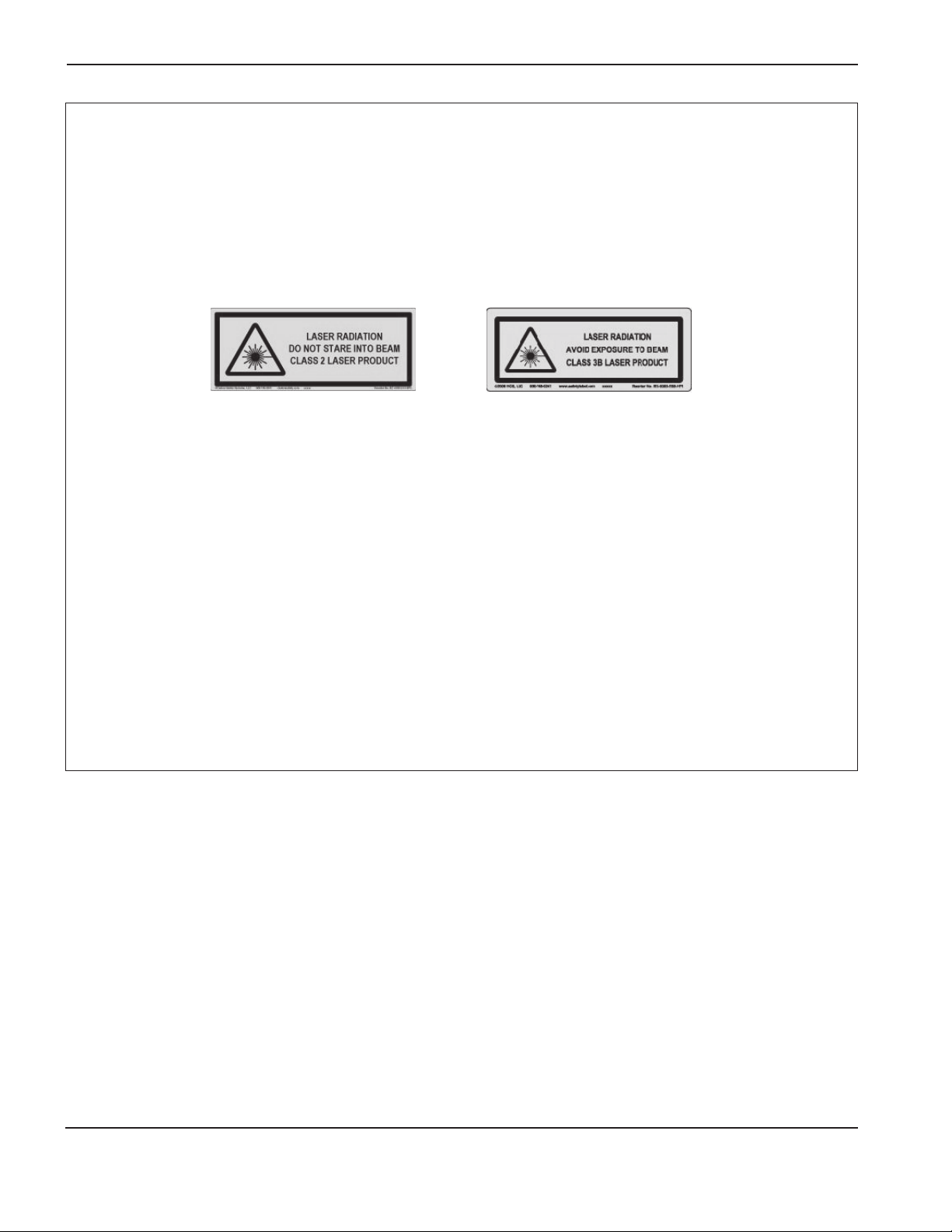
SÉCURITÉ
RADIATION AU LASER
L’exposition à une sortie laser peut provoquer des problèmes visuels graves. Éviter un contact
direct avec les yeux.
Pour votre aisance et votre sécurité, l’une des étiquettes de radiation au laser suivantes a été installée sur les
produits Hypertherm près de la sortie du faisceau laser du boîtier. Ont également été fournies la sortie maximale
(mV), la longueur d’onde émise (nM) et au besoin, la durée d’impulsion.
Autres consignes de sécurité relatives au laser:
• Consulter un expert local pour les réglementations
locales sur le laser. Une formation sur la sécurité
relative au laser peut être nécessaire.
• Ne pas autoriser le personnel non formé à faire
fonctionner le laser. Il peut s’avérer dangereux pour
cepersonnel.
• Ne jamais regarder l’intérieur ou le faisceau du laser.
• Positionner le laser selon les instructions afin d’éviter
un éventuel contact avec les yeux.
• Ne pas utiliser le laser sur des pièces à couper
réflectives.
• Ne pas utiliser des outils optiques pour visualiser
lefaisceau du laser.
• Ne pas démonter ou retirer le laser ou son capot.
• Toute modification du laser ou du produit peut
accroître le risque de radiation au laser.
• L’utilisation des réglages ou le suivi des procédures
autres que celles spécifiées dans ce manuel peut
entraîner un risque de radiation au laser.
• Ne pas faire fonctionner l’appareil en présence
d’explosifs tels que des liquides et des gaz
inflammables ou la poussière.
• Utiliser uniquement les pièces et accessoires laser
recommandés ou fournis par le fabricant pour votre
modèle.
• Les travaux de réparation et d’entretien DOIVENT
êtreeffectués par un personnel qualifié.
• Ne pas retirer ou détruire l’étiquette de sécurité
dulaser.
1a-10 Hypertherm
03/10
Page 39

SÉCURITÉ
SYMBOLES ET MARQUAGE
Votre produit Hypertherm peut comporter une ou plusieurs des marques suivantes sur sa plaque signalétique ou
àproximité. En raison des différends et des conflits relatifs aux règlements nationaux, toutes les marques ne sont
pasappliquées à chaque version d’un produit.
Symbole de marqueS
Le symbole de marqueS indique que la source de courant et la torche conviennent pour les travaux
effectuésdans les milieux à risque accru de choc électrique selon l’IEC 60974-1.
Marque CSA
Les produits Hypertherm portant la marque CSA sont conformes aux réglementations des États-Unis et du
Canada pour la sécurité des produits. Les produits ont été évalués, testés et certifiés par CSA-International.
Le produit peut autrement porter la marque d’autres laboratoires d’essais reconnus à l’échelle nationale
(NRTL) agréés à la fois aux États-Unis et au Canada, par exemple: Underwriters Laboratories, Incorporated
(UL) ou TÜV.
Marque CE
Le marquage CE signifie: déclaration de conformité du fabricant aux directives et normes européennes
applicables. Seules les versions des produits Hypertherm portant la marque CE située sur ou à proximité
de la plaque signalétique ont été testées pour conformité à la directive européenne «basse tension»
et la directive européenne «compatibilité électromagnétique» (CEM). Les filtres CEM devant être
en conformité avec ladirective européenne CEM sont intégrés dans les produits portant la marque CE.
Marque GOST-R
Les versions CE des produits Hypertherm qui portent la marque de conformité GOST-R répondent aux
exigences de sécurité du produit et de CEM en vue de l’exportation à la Fédération russe.
Marque c-Tick
Les versions CE des produits Hypertherm portant la marque c-Tick sont conformes aux règlements CEM
prescrits pour la vente en Australie et en Nouvelle-Zélande.
Marque CCC
La marque de certification obligatoire en Chine (CCC) indique que le produit a été mis à l’essai et déclaré
conforme aux règlements de sécurité du produit prescrits pour la vente en Chine.
Hypertherm 1a-11
03/10
Page 40

SÉCURITÉ
ÉTIQUETTES DE SÉCURTITÉ
Cette étiquette est affichée sur certaines sources de courant. Il est important que l’opérateur et le technicien
d’entretien comprennent la signification des symboles de sécurité.
Read and follow these instructions, employer safety
practices, and material safety data sheets. Refer to
ANS Z49.1, “Safety in Welding, Cutting and Allied
Processes” from American Welding Society
(http://www.aws.org) and OSHA Safety and Health
Standards, 29 CFR 1910 (http://www.osha.gov).
WARNING
Plasma cutting can be injurious to operator and persons
in the work area. Consult manual before operating. Failure
to follow all these safety instructions can result in death.
1. Cutting sparks can cause explosion or fire.
1.1 Do not cut near flammables.
1.2 Have a fire extinguisher nearby and ready to use.
1.3 Do not use a drum or other closed container as a cutting table.
2. Plasma arc can injure and burn; point the nozzle away
from yourself. Arc starts instantly when triggered.
2.1 Turn off power before disassembling torch.
2.2 Do not grip the workpiece near the cutting path.
2.3 Wear complete body protection.
3. Hazardous voltage. Risk of electric shock or burn.
3.1 Wear insulating gloves. Replace gloves when wet or damaged.
3.2 Protect from shock by insulating yourself from work and ground.
3.3 Disconnect power before servicing. Do not touch live parts.
4. Plasma fumes can be hazardous.
4.1 Do not inhale fumes.
4.2 Use forced ventilation or local exhaust to remove the fumes.
4.3 Do not operate in closed spaces. Remove fumes with ventilation.
5. Arc rays can burn eyes and injure skin.
5.1 Wear correct and appropriate protective equipment to protect
head, eyes, ears, hands, and body. Button shirt collar. Protect ears
from noise. Use welding helmet with the correct shade of filter.
6. Become trained.
equipment. Use torches specified in the manual. Keep non-qualified
personnel and children away.
7. Do not remove, destroy, or cover this label.
Replace if it is missing, damaged, or worn (PN 110584 Rev C).
Only qualified personnel should operate this
AVERTISSEMENT
Le coupage plasma peut être préjudiciable pour l’opérateur et les personnes qui se
trouvent sur les lieux de travail. Consulter le manuel avant de faire fonctionner. Le
non respect des ces instructions de sécurité peut entraîner la mort.
1. Les étincelles de coupage peuvent provoquer une explosion
ou un incendie.
1.1 Ne pas couper près des matières inflammables.
1.2 Un extincteur doit être à proximité et prêt à être utilisé.
1.3 Ne pas utiliser un fût ou un autre contenant fermé comme table de coupage.
2. L’arc plasma peut blesser et brûler; éloigner la buse de soi.
Il s’allume instantanément quand on l’amorce;
2.1 Couper l’alimentation avant de démonter la torche.
2.2 Ne pas saisir la pièce à couper de la trajectoire de coupage.
2.3 Se protéger entièrement le corps.
3. Tension dangereuse. Risque de choc électrique ou de brûlure.
3.1 Porter des gants isolants. Remplacer les gants quand ils sont humides ou
endommagés.
3.2 Se protéger contre les chocs en s’isolant de la pièce et de la terre.
3.3 Couper l’alimentation avant l’entretien. Ne pas toucher les pièces sous tension.
4. Les fumées plasma peuvent être dangereuses.
4.1 Ne pas inhaler les fumées
4.2 Utiliser une ventilation forcée ou un extracteur local pour dissiper les fumées.
4.3 Ne pas couper dans des espaces clos. Chasser les fumées par ventilation.
5. Les rayons d’arc peuvent brûler les yeux et blesser la peau.
5.1 Porter un bon équipement de protection pour se protéger la tête, les yeux, les
oreilles, les mains et le corps. Boutonner le col de la chemise. Protéger les oreilles
contre le bruit. Utiliser un masque de soudeur avec un filtre de nuance appropriée.
6. Suivre une formation.
fonctionner cet équipement. Utiliser exclusivement les torches indiquées dans le
manual. Le personnel non qualifié et les enfants doivent se tenir à l’écart.
7. Ne pas enlever, détruire ni couvrir cette étiquette.
La remplacer si elle est absente, endommagée ou usée (PN 110584 Rev C).
Seul le personnel qualifié a le droit de faire
1a-12 Hypertherm
03/10
Page 41

SÉCURITÉ
ÉTIQUETTE DE SÉCURITÉ
Cette étiquette est affichée sur certaines sources de courant. Il est
important que l’opérateur et le technicien d’entretien comprennent
la signification des symboles de sécurité. Les numéros de la liste
correspondent aux numéros des images.
1. Les étincelles de coupage peuvent
provoquer une explosion ou un incendie.
1.1 Ne pas couper près des matières
inflammables.
1.2 Un extincteur doit se trouver sur les lieux
et être prêt à être utilisé.
1.3 Ne pas utiliser un fût ou un autre
contenant fermé comme table de coupe.
2. L’arc plasma peut blesser et brûler;
nejamais pointer la buse vers soi.
L’arcs’amorce instantanément quand
on appuie sur la gâchette.
2.1 Couper l’alimentation avant de démonter
la torche.
2.2 Ne pas saisir la pièce à couper près
dela trajectoire de coupage.
2.3 Se protéger entièrement le corps.
3. Tension dangereuse. Risque de choc
électrique ou de brûlure.
3.1 Porter des gants isolants. Remplacer les
gants s’ils sont humides ou endommagés.
3.2 Se protéger contre les chocs en s’isolant
de la pièce et de la terre.
3.3 Couper l’alimentation avant de procéder
à l’entretien. Ne pas toucher les pièces
sous tension.
4. Les fumées du plasma peuvent être
dangereuses.
4.1 Ne pas inhaler les fumées.
4.2 Utiliser une ventilation forcée ou par
extraction locale pour éliminer les fumées.
4.3 Ne pas utiliser dans des espaces clos.
Éliminer les fumées avec la ventilation.
5. Les rayons d’arc peuvent brûler les yeux
et blesser la peau.
5.1 Porter un bon équipement de protection
pour se protéger la tête, les yeux, les
oreilles, les mains et le corps. Boutonner
le col de la chemise. Protéger les oreilles
contre le bruit. Utiliser le masque de
soudage avec le filtre ayant le bon indice
de protection.
6. Suivre une formation. Seul le personnel
qualifié doit faire fonctionner cet
équipement. Utiliser les torches prescrites
dans le manuel. Tenir le personnel non
qualifié et les enfants à l’écart.
7. Ne pas enlever, détruire ou couvrir
cette étiquette. La remplacer si elle
estmanquante, endommagée ou usée.
Hypertherm 1a-13
03/10
Page 42

SÉCURITÉ
1a-14 Hypertherm
03/10
Page 43

Sección 1b
SEGURIDAD
En esta sección:
Reconocimiento de información de seguridad ...................................................................................................................................1-2
Cumplimiento de instrucciones de seguridad.....................................................................................................................................1-2
Riesgos de electrocución ........................................................................................................................................................................1-2
Las descargas eléctricas pueden matar ...............................................................................................................................................1-3
Los cortes pueden producir incendios o explosiones .......................................................................................................................1-4
Los vapores tóxicos pueden producir lesiones o la muerte .............................................................................................................1-5
Seguridad de toma a tierra ......................................................................................................................................................................1-6
La electricidad estática puede dañar las placas de circuitos ..........................................................................................................1-6
Seguridad de equipos de gas comprimido .........................................................................................................................................1-6
Los cilindros de gas pueden explotar si están dañados ..................................................................................................................1-6
El arco de plasma puede producir lesiones y quemaduras .............................................................................................................1-7
Los rayos del arco pueden quemar los ojos y la piel .........................................................................................................................1-7
Funcionamiento de marcapasos y audífonos ......................................................................................................................................1-8
Los ruidos pueden dañar la audición ....................................................................................................................................................1-8
El arco de plasma puede dañar las tuberías congeladas .................................................................................................................1-8
Información acerca de la recolección de polvo seco ........................................................................................................................1-9
Radiación láser ........................................................................................................................................................................................ 1-10
Símbolos y marcas .................................................................................................................................................................................1-11
Etiquetas de advertencia .......................................................................................................................................................................1-12
Hypertherm 1b-1
03/10
Page 44

SEGURIDAD
RECONOCIMIENTO
DE INFORMACIÓN
DE SEGURIDAD
Los símbolos incluidos en esta sección se usan para
identificar posibles peligros. Cuando vea un símbolo de
seguridad en este manual o en la máquina, debe tomar
conciencia del riesgo de lesiones personales y seguir
las instrucciones relacionadas para evitar ese riesgo.
CUMPLIMIENTO
DE INSTRUCCIONES
DE SEGURIDAD
Lea cuidadosamente todos los mensajes de seguridad
de este manual y todas las etiquetas de seguridad de
la máquina.
• Mantenga las etiquetas de seguridad de la máquina
en buen estado. Reponga de inmediato las etiquetas
dañadas o faltantes.
• Aprenda a operar la máquina y usar los controles de
manera adecuada. No permita que nadie la opere sin
las instrucciones correspondientes.
• Asegúrese de que la máquina esté en buenas condiciones
operativas. Las modificaciones no autorizadas pueden
afectar la seguridad y la vida útil de la máquina.
PELIGRO ADVERTENCIA PRECAUCIÓN
Hypertherm utiliza las pautas del American National
Standards Institute en relación con los símbolos y las
palabras de aviso de seguridad. Junto a los símbolos de
seguridad, aparecen palabras de aviso como PELIGRO
o ADVERTENCIA. La palabra PELIGRO identifica a los
riesgos más graves.
• Las etiquetas de seguridad de PELIGRO
yADVERTENCIA están colocadas cerca de
losriesgos específicos que presenta la máquina.
• Los mensajes de seguridad de PELIGRO aparecen
en este manual antes de las instrucciones
relacionadas a procesos que pueden producir
lesiones o la muerte si no se siguen correctamente.
• Los mensajes de seguridad de ADVERTENCIA
aparecen en este manual antes de las instrucciones
relacionadas a procesos que pueden producir
lesiones o la muerte si no se siguen correctamente.
• Los mensajes de seguridad de PRECAUCIÓN
aparecen en este manual antes de las instrucciones
relacionadas a procesos que pueden producir
lesiones menores o daños en los equipos si no
sesiguen correctamente.
RIESGOS DE ELECTROCUCIÓN
• Sólo el personal capacitado y autorizado puede abrir
este equipo.
• Si el equipo está conectado en forma permanente,
apáguelo e implemente un cierre “con llave y etiqueta”
de la energía antes de abrir el armazón.
• Si el suministro de energía se realiza a través de un
cable, desenchufe la unidad antes de abrir el armazón.
• Otras personas deberán suministrar las cubiertas para
enchufes bloqueables y los elementos de desconexión
bloqueables.
• Espere 5 minutos luego de cortar la energía y antes
de ingresar en el armazón, a fin de permitir que
la energía almacenada se descargue.
1b-2 Hypertherm
• Si no se puede cortar el suministro de energía del
equipo mientras se abre el armazón para realizar
reparaciones, es posible que se produzcan peligros
de explosión de arco eléctrico. Siga TODOS los
requisitos locales (NFPA 70E en los EE. UU.) en
relación con las practicas de trabajo seguro y con el
equipo de protección personal al realizar reparaciones
en equipos energizados.
• El armazón debe permanecer cerrado y se debe
verificar que la continuidad a tierra física al armazón
sea la adecuada antes de operar el equipo y luego
de moverlo, abrirlo o realizarle reparaciones.
• Siempre siga estas instrucciones para desconectar
la energía antes de inspeccionar o cambiar las piezas
consumibles de la antorcha.
03/10
Page 45

SEGURIDAD
LAS DESCARGAS ELÉCTRICAS PUEDEN MATAR
El contacto con piezas eléctricas con corriente puede
causar una descarga mortal o quemaduras graves.
• Cuando el sistema de plasma está en funcionamiento,
se completa un circuito eléctrico entre la antorcha y la
pieza a cortar. La pieza a cortar y cualquier objeto que
la esté tocando pasan a formar parte de este circuito.
• Nunca toque el cuerpo de antorcha, la pieza a cortar
ni el agua de la mesa de agua cuando el sistema
de plasma esté en funcionamiento.
Prevención de descargas eléctricas
Todos los sistemas de plasma Hypertherm
usan voltajes altos en el proceso de corte
(suelen ser de 200 a 400VCD). Tome las
siguientes precauciones al operar el sistema:
• Use botas y guantes aislados, y mantenga su cuerpo
ysu vestimenta secos.
• Asegúrese de que ninguna parte de su cuerpo esté
encontacto con una superficie mojada mientras usa
el sistema de plasma.
• Aíslese de la pieza de trabajo y la tierra con una
alfombra o cubierta aislante de tamaño suficiente
para prevenir cualquier contacto físico con la pieza
de trabajo o la tierra. Tenga mucha precaución si
el lugar de trabajo o los alrededores están húmedos.
• Instale un interruptor de desconexión con fusibles
detamaño apropiado cerca de la fuente de energía.
Este interruptor permitirá al operador cortar la fuente
de energía rápidamente ante una emergencia.
• Al usar una mesa de agua, asegúrese de que esté
bien puesta a tierra.
• Instale y ponga a tierra el equipo respetando el manual
de instrucciones y los códigos nacionales y locales.
• Inspeccione con frecuencia el cable de potencia
de alimentación para detectar daños o rajaduras
en la cubierta. Reemplace los cables dañados
de inmediato. Los cables pelados pueden ser
mortales.
• Inspeccione las mangueras de la antorcha y reemplace
las que estén dañadas.
• No levante la pieza a cortar ni los residuos de corte
durante la tarea. Deje la pieza a cortar en su lugar
o en la mesa de trabajo con el cable de trabajo
colocado durante el proceso de corte.
• Antes de controlar, limpiar o reemplazar piezas de
la antorcha, desconecte la alimentación principal
odesenchufe la fuente de energía.
• Nunca anule ni puentee los bloqueos de seguridad.
• Antes de quitarle la cubierta a una fuente de energía
o recinto del sistema, desconecte la potencia
dealimentación eléctrica. Espere 5 minutos antes
dedesconectar la alimentación principal, para permitir
la descarga de los condensadores.
• Nunca opere el sistema de plasma sin las cubiertas
de la fuente de energía en su lugar. Si las conexiones
de la fuente de energía están expuestas, presentan
unalto riesgo de electrocución.
• Al hacer las conexiones de entrada, una primero
elconductor de puesta a tierra correspondiente.
• Cada sistema de plasma Hypertherm está diseñado
para usarse únicamente con antorchas Hypertherm
específicas. No utilice otras antorchas, ya que
podrían sobrecalentarse y presentar un riesgo para
laseguridad.
Hypertherm 1b-3
03/10
Page 46

SEGURIDAD
LOS CORTES PUEDEN PRODUCIR INCENDIOS
OEXPLOSIONES
Prevención de incendios
• Compruebe la seguridad del lugar antes de realizar
cortes. Tenga disponible un extintor de incendios
cerca del lugar.
• Mantenga todas las sustancias inflamables a 10m
dedistancia del área de corte.
• Temple o deje enfriar el metal caliente antes de
manipularlo o que entre en contacto con materiales
combustibles.
• Nunca corte envases que contengan materiales
potencialmente inflamables; primero deben vaciarse
ylimpiarse bien.
• Ventile las atmósferas que puedan ser inflamables
antes de realizar cortes.
• Al cortar con oxígeno como gas plasma, es obligatorio
el uso de un sistema de ventilación de escape.
Prevención de explosiones
• No use el sistema de plasma si puede haber polvo
ovapores explosivos.
• No corte cilindros presurizados, tuberías ni envases
cerrados.
• No corte envases que tenían materiales combustibles.
ADVERTENCIA
Peligro de explosión
Argón-hidrógeno y metano
El hidrógeno y el metano son gases inflamables que
presentan un riesgo de explosión. Mantenga las llamas
alejadas de los cilindros y las mangueras con metano
omezclas de hidrógeno. Evite que las llamas y las
chispas se acerquen a la antorcha cuando use plasma
de metano o argón-hidrógeno.
ADVERTENCIA
Peligro de explosión
Cortes bajo el agua con
gases combustibles
• No corte aluminio bajo el agua o cuando el agua esté
en contacto con la parte inferior del aluminio.
• Cortar aluminio bajo el agua o cuando el agua esté
en contacto con la parte inferior del aluminio puede
provocar una situación explosiva que podría detonarse
durante las operaciones de corte por plasma.
ADVERTENCIA
Explosión de hidrógeno
al cortar aluminio
• No realice cortes bajo el agua con gases
combustibles que contengan hidrógeno.
• Realizar cortes bajo el agua con gases combustibles
que contienen hidrógeno puede provocar una situación
explosiva que podría detonarse durante operaciones
decorte por plasma.
1b-4 Hypertherm
03/10
Page 47

SEGURIDAD
LOS VAPORES TÓXICOS PUEDEN PRODUCIR LESIONES
O LA MUERTE
El arco de plasma es la fuente de calor usada para el
corte. Por lo tanto, aunque el arco de plasma mismo no
sea fuente de vapores tóxicos, el material que se corta
puede producir estos vapores o gases que agotan
eloxígeno.
Los vapores producidos varían según el metal que se
corte. Algunos de los metales que pueden producir
vapores tóxicos son, entre otros, el acero inoxidable,
elacero al carbono, el zinc (galvanizado) y el cobre.
En algunos casos, el metal puede estar recubierto por
una sustancia que podría producir vapores tóxicos.
Losrevestimientos tóxicos incluyen, entre otros, elplomo
(de algunas pinturas), el cadmio (de algunas pinturas
ytapaporos) y el berilio.
Los gases producidos por el corte por plasma varían
según el material y el método de corte, pero pueden
incluir ozono, óxidos de nitrógeno, cromo hexavalente,
hidrógeno y otras sustancias contenidas o liberadas
porel material de corte.
Se deben tomar precauciones para minimizar la
exposición a los vapores producidos en cualquier
proceso industrial. Según la composición química
y la concentración de los vapores (junto con otros
factores, como la ventilación), puede haber riesgo
de contraer enfermedades físicas, como defectos
congénitos o cáncer.
El propietario del equipo y las instalaciones debe
analizar la calidad del aire del lugar donde se usa
elequipo, para asegurarse de que cumpla con todas
lasnormas y reglamentaciones locales y nacionales.
La calidad del aire de cualquier lugar de trabajo
depende de variables específicas del lugar, como:
• Diseño de la mesa (con agua, en seco, bajo el agua).
• Composición del material, acabado de la superficie
ycomposición de los revestimientos.
• Volumen de material descartado.
• Duración del corte o ranurado.
• Tamaño, volumen de aire, ventilación y filtración
delárea de trabajo.
• Equipos de protección personal.
• Cantidad de sistemas de soldadura y corte en
funcionamiento.
• Otros procesos del lugar que pueden producir
vapores.
Si el lugar de trabajo debe cumplir con reglamentaciones
nacionales o locales, sólo los controles o pruebas
realizados en el lugar pueden determinar si los niveles
seencuentran dentro de lo permitido.
Para reducir el riesgo de exposición a vapores:
• Quite todos los revestimientos y solventes del metal
antes de cortar.
• Use la ventilación de escape local para eliminar los
vapores del aire.
• No inhale los vapores. Use un respirador con suministro
de aire al cortar metales que contienen o pueden
contener elementos tóxicos, o están recubiertos con
estos elementos.
• Asegúrese de que las personas que usen equipos
de soldadura o corte, y respiradores con suministro
de aire estén calificadas y capacitadas en el uso
adecuado de estos equipos.
• Nunca corte envases que contengan materiales
potencialmente tóxicos. Vacíe y limpie bien el envase
antes de cortarlo.
• Realice controles o pruebas de la calidad del aire del
lugar, según sea necesario.
• Consulte a un experto local sobre la implementación
de un plan para asegurarse de que la calidad del aire
sea segura.
Hypertherm 1b-5
03/10
Page 48

SEGURIDAD
SEGURIDAD DE TOMA A TIERRA
Cable de trabajo Sujete el cable de trabajo firmemente
a la pieza a cortar o la mesa de trabajo, estableciendo un
buen contacto metal con metal. No lo conecte a la pieza
que se caerá cuando se termine el corte.
Mesa de trabajo Ponga a tierra la mesa de trabajo,
en cumplimiento con los códigos eléctricos locales
ynacionales.
Potencia de alimentación (entrada)
• Asegúrese de conectar el conductor de puesta
a tierra del cable de alimentación con la puesta
a tierra de la caja de desconexión.
LA ELECTRICIDAD ESTÁTICA PUEDE DAÑAR LAS PLACAS
DE CIRCUITOS
Tome las precauciones necesarias para manipular placas de circuito impreso:
• Guarde las placas de PC en recipientes antiestáticos.
• Use una cinta de muñeca puesta a tierra para manipular las placas de PC.
• Si la instalación del sistema de plasma implica
laconexión del cable de alimentación a la fuente
deenergía, asegúrese de conectar adecuadamente
el conductor de puesta a tierra del cable de
alimentación.
• Coloque el conductor de puesta a tierra del cable
dealimentación en el borne antes que los demás;
losotros conductores de puesta a tierra deben ir
encima del conductor del cable de alimentación.
Ajuste bien la tuerca de retención.
• Ajuste todas las conexiones eléctricas para evitar
elcalentamiento excesivo.
SEGURIDAD DE EQUIPOS
DE GAS COMPRIMIDO
• Nunca lubrique los reguladores o las válvulas
decilindros con aceite o grasa.
• Use únicamente los cilindros de gas, los reguladores,
las mangueras y los accesorios diseñados
específicamente para esa aplicación.
• Mantenga todos los equipos de gas comprimido
y las piezas relacionadas en buen estado.
• Etiquete e identifique con colores todas las
mangueras de gas, para saber el tipo de gas que
transporta cada manguera. Consulte los códigos
nacionales y locales correspondientes.
LOS CILINDROS DE GAS
PUEDEN EXPLOTAR SI
ESTÁN DAÑADOS
Los cilindros de gas tienen gas bajo alta presión. Si se
dañan, pueden explotar.
• Los cilindros de gas comprimido deben manipularse
y usarse respetando los códigos nacionales y locales.
• Use únicamente cilindros que estén en posición
vertical y bien sujetos en su lugar.
• Mantenga la tapa protectora colocada en la válvula,
a menos que el cilindro esté conectado o en uso.
• Nunca permita que haya contacto eléctrico entre
el arco de plasma y un cilindro.
• Nunca exponga los cilindros al calor excesivo,
las chispas, la escoria ni la llama directa.
• Nunca use un martillo, llave ni otra herramienta para
abrir una válvula de cilindro atascada.
1b-6 Hypertherm
03/10
Page 49

SEGURIDAD
EL ARCO DE PLASMA PUEDE PRODUCIR LESIONES
Y QUEMADURAS
Antorchas de encendido inmediato
El arco de plasma se enciende de inmediato al activar
el interruptor de la antorcha.
El arco de plasma puede cortar los guantes y la piel
rápidamente.
• Evite el contacto con la punta de la antorcha.
• No ponga piezas de metal cerca de la ruta de corte.
• Nunca apunte la antorcha en dirección a usted
o a otras personas.
LOS RAYOS DEL ARCO PUEDEN QUEMAR
LOS OJOS Y LA PIEL
Protección ocular El arco de plasma produce rayos visibles e invisibles (ultravioletas e infrarrojos) que pueden
quemar los ojos y la piel.
• Use la protección ocular que exigen los códigos nacionales y locales.
• Las lentes de la protección ocular (anteojos o gafas de seguridad con protección lateral, y careta de soldador)
deben contar con el sombreado adecuado para proteger los ojos de los rayos ultravioletas e infrarrojos del arco.
Protección cutánea Use vestimenta de protección para evitar las quemaduras producidas por la luz ultravioleta,
las chispas y el metal caliente.
• Guantes de seguridad, calzado de seguridad y casco.
• Vestimenta ignífuga para cubrir todas las áreas expuestas.
• Pantalones sin dobladillo, para evitar el ingreso de chispas y escoria.
• Antes del corte, sáquese de los bolsillos todo material combustible, como los encendedores con butano o los fósforos.
Área de corte Prepare el área de corte para reducir el reflejo y la emisión de luz ultravioleta:
• Pinte las paredes y otras superficies de colores oscuros, para reducir el reflejo.
• Use pantallas o barreras protectoras para resguardar a los demás del centelleo y el resplandor.
• Advierta a las demás personas que no deben mirar el arco. Coloque carteles o anuncios.
Corriente
del arco
(amperios)
Inferior a 40 A 5 5 8 9
41 a 60 A 6 6 8 9
61 a 80 A 8 8 8 9
81 a 125 A 8 9 8
126 a 150 A 8 9 8 10
151 a 175 A 8 9
176 a 250 A 8 9 8 12
251 a 300 A 8 9 8 13
301 a 400 A 9 12 9 13
401 a 800 A 10 14 10
Número mínimo
de sombra de
protección
(ANSIZ49.1:2005)
Número de sombra
sugerido para
confort (ANSI
Z49.1:2005)
OSHA 29CFR
1910.133(a)(5)
8
Europa
EN168:2002
9
11
Hypertherm 1b-7
03/10
Page 50

SEGURIDAD
FUNCIONAMIENTO DE MARCAPASOS Y AUDÍFONOS
El funcionamiento de marcapasos y audífonos puede
verse afectado por los campos magnéticos de las altas
corrientes.
Las personas que usan marcapasos o audífonos deben
consultar a un médico antes de acercarse a una operación
de corte o ranurado por arco de plasma.
Para reducir el riesgo que presentan los campos
magnéticos:
• Mantenga el cable de trabajo y los conductos
de antorcha a un costado, alejados del cuerpo.
LOS RUIDOS PUEDEN DAÑAR LA AUDICIÓN
Realizar cortes con un arco de plasma puede superar
los niveles de ruido aceptables, según se definen
en los códigos locales en muchas aplicaciones. La
exposición prolongada a ruidos excesivos puede dañar
la audición. Siempre use una protección apropiada para
los oídos al realizar cortes o ranurados, a menos que
se haya verificado que, en función de las mediciones
de los niveles de presión de sonido tomadas en el sitio
instalado, no sea necesario utilizar protección auditiva
personal, de acuerdo con los códigos internacionales,
regionales y locales correspondientes.
Se puede obtener una reducción significativa de
los ruidos mediante la incorporación de controles
de ingeniería simples a las mesas de corte, como
barreras o cortinas ubicadas entre el arco de
plasma y la estación de trabajo; además, se puede
ubicar laestación de trabajo en un lugar alejado
delarco deplasma. Se deben implementar controles
• Haga pasar las mangueras de la antorcha lo más
cerca posible del cable de trabajo.
• No se enrosque ni apoye los conductos de antorcha
ni el cable de trabajo en el cuerpo.
• Manténgase lo más alejado de la fuente de energía
como sea posible.
administrativos en el lugar de trabajo para restringir
elacceso, limitar el tiempo de exposición del operador,
cubrir áreas de trabajo ruidosas o tomar las medidas
necesarias para reducir la reverberación en áreas de
trabajo al colocar mecanismos de absorción de ruidos.
Se debe utilizar una protección auditiva si el ruido es
perjudicial o si existe el riesgo de que se produzcan
daños a la audición una vez implementados todos los
demás controles administrativos y de ingeniería. Si es
necesario utilizar una protección auditiva, utilice sólo los
dispositivos de protección personal aprobados, como
protectores para las orejas o tapones para los oídos
con una calificación de reducción de ruidos adecuada
para la situación. Advierta a las demás personas que
trabajan en el área sobre los posibles riesgos que
presentan los ruidos. Además, la protección para los
oídos puede evitar que salpicaduras calientes ingresen
en la oreja.
EL ARCO DE PLASMA PUEDE DAÑAR LAS TUBERÍAS
CONGELADAS
Las tuberías pueden dañarse o reventar si se intenta descongelarlas con una antorcha de plasma.
1b-8 Hypertherm
03/10
Page 51

SEGURIDAD
INFORMACIÓN ACERCA DE LA RECOLECCIÓN DE POLVO SECO
En algunos sitios, el polvo seco puede presentar un
posible riesgo de explosión.
La edición 2007 de la norma 68 NFPA de la U.S. National
Fire Protection Association, “Explosion Protection by
Deflagration Venting” (Protección contra explosiones
mediante ventilación en caso de deflagración)
proporciona los requisitos para el diseño, la ubicación,
la instalación, el mantenimiento y el uso dedispositivos
y sistemas para ventilar presiones y gases de combustión
después de un evento dedeflagración. Consulte al
fabricante o instalador desistemas de recolección de
polvo seco acerca de los requisitos aplicables antes
de instalar un nuevo sistema de recolección de polvo
seco o de realizar cambios significativos en los materiales
o procesos utilizados con un sistema de recolección
de polvo seco existente.
Consulte la “Autoridad con jurisdicción” (AHJ, Authority
Having Jurisdiction) para determinar si la edición de la
norma 68 de la NFPA se ha “adoptado por referencia”
en los códigos de construcción locales.
Consulte la norma NFPA68 para conocer las
definiciones y explicaciones de los términos aprobados
como deflagración, AHJ, adoptado por referencia, valor
Kst, índice de deflagración y otros términos.
Nota 1 – La interpretación por parte de Hypertherm de
estos nuevos requisitos implica que, a menos que se
haya realizado una evaluación específica del lugar para
determinar que el polvo generado no es combustible,
la edición 2007 de NFPA 68 requiere el uso de
ventilaciones de explosión diseñadas para el peor valor
Kst (consulte el anexo F) que se podría generar a causa
del polvo, de manera que se puedan diseñar el tipo y el
tamaño de ventilación de explosión. La norma NFPA 68
no identifica específicamente que el corte por plasma
ni otros procesos de corte térmico requieran sistemas
de ventilación en caso de deflagración; sin embargo,
síaplica estos nuevos requisitos a todos los sistemas
de recolección de polvo seco.
Nota 2 – Los usuarios de los manuales de Hypertherm
deben consultar y cumplir todas las regulaciones
yleyes federales, estatales y locales correspondientes.
Mediante la publicación de sus manuales, Hypertherm
no pretende instar la implementación de acciones
que no cumplen los estándares y las regulaciones
aplicables; asimismo, no se debe interpretar que este
manual persigue dicho fin.
Hypertherm 1b-9
03/10
Page 52

SEGURIDAD
RADIACIÓN LÁSER
La exposición a la salida del láser puede provocar graves daños oculares. Evite la exposición
ocular directa.
Para su conveniencia y seguridad, en todos los productos Hypertherm que usan un láser, se ha aplicado una
de las siguientes etiquetas de radiación láser en el producto, cerca de lugar donde el haz láser sale del bastidor.
También se proporcionan los valores de salida máxima (mV), la longitud de onda emitida (nM) y, si corresponde,
la duración de pulso.
Instrucciones de seguridad adicionales sobre
la utilización de productos con láser:
• Consulte a un experto para conocer las regulaciones
locales sobre la utilización de láser. Es posible que
se exija una capacitación de seguridad para el uso
de láser.
• No permita que el personal no capacitado opere
el láser. El láser puede ser peligroso si es utilizado
por personal no capacitado.
• No mire el haz o la apertura del láser en ningún
momento.
• Ubique el láser como se indica, a fin de evitar
contacto ocular no deseado.
• No utilice el láser en piezas a cortar reflectantes.
• No utilice herramientas ópticas para visualizar
o reflectar el haz del láser.
• No desarme ni extraiga el láser ni la cubierta
de apertura.
• Las modificaciones realizadas al láser o al producto
pueden aumentar el riesgo de que se produzca
radiación láser.
• El uso de ajustes o la implementación de
procedimientos que no sean aquellos especificados
en este manual pueden provocar una exposición
peligrosa a la radiación láser.
• No opere el producto en atmósferas explosivas, como
en presencia de polvo, gases o líquidos inflamables.
• Sólo utilice los accesorios y las piezas del láser que
el fabricante suministra o recomienda para su modelo.
• Las reparaciones y el mantenimiento SE DEBEN
llevar a cabo por personal calificado.
• No extraiga ni mutile la etiqueta de seguridad
del láser.
1b-10 Hypertherm
03/10
Page 53

SEGURIDAD
SÍMBOLOS Y MARCAS
Su producto Hypertherm puede contener alguna de las siguientes marcas en la placa de datos o cerca de ella. Debido
a las diferencias y los conflictos con las regulaciones nacionales, no todas las marcas se aplican a todas las versiones
de un producto.
Marca símbolo S
La marca símbolo S indica que la fuente de energía y la antorcha son aptas para operaciones llevadas a cabo
en entornos en los que existe un alto peligro de descargas eléctricas, de acuerdo con la norma IEC 60974-1.
Marca CSA
Los productos de Hypertherm que tienen la marca CSA cumplen con los reglamentos de seguridad de los
productos de los Estados Unidos y Canadá. Estos productos han sido evaluados, probados y certificados
por CSA-International. De manera alternativa, es posible que el producto tenga una marca colocada por otro
Laboratorio de pruebas reconocido a nivel nacional (NRTL, por sus siglas en inglés) autorizado en los Estados
Unidos y en Canadá, por ejemplo, Underwriters Laboratories, Incorporated (UL) o TÜV.
Marca CE
La marca CE indica la declaración de cumplimiento del fabricante con las normas y las directivas europeas
aplicables. Sólo se considerarán probadas para cumplimiento con las Directivas europeas de baja tensión
y con las Directivas europeas de compatibilidad electromagnética (EMC) aquellas versiones de los productos
Hypertherm que tengan la marca CE colocada sobre la placa de datos o cerca de ésta. Aquellos filtros de
EMC que deban cumplir con las Directivas europeas de EMC se han incorporado a las versiones de los
productos con la marca CE.
Marca GOST-R
Las versiones CE de los productos de Hypertherm que incluyen una marca de conformidad GOST-R cumplen
los requisitos de compatibilidad electromagnética (EMC) y de seguridad del producto para exportación
a la Federación Rusa.
Marca c-Tick
Las versiones CE de los productos de Hypertherm que incluyen una marca c-Tick cumplen las regulaciones
de EMC para la venta del producto en Australia y Nueva Zelanda.
Marca CCC
La marca China Compulsory Certification (CCC) indica que se ha evaluado el producto y que este cumple
las regulaciones de seguridad del producto requeridas para su venta en China.
Hypertherm 1b-11
03/10
Page 54

SEGURIDAD
ETIQUETAS DE ADVERTENCIA
Esta etiqueta de advertencia se coloca en ciertas fuentes de energía. Es importante que el operador y el técnico
de mantenimiento entiendan las ideas que transmiten estos símbolos de advertencia.
Read and follow these instructions, employer safety
practices, and material safety data sheets. Refer to
ANS Z49.1, “Safety in Welding, Cutting and Allied
Processes” from American Welding Society
(http://www.aws.org) and OSHA Safety and Health
Standards, 29 CFR 1910 (http://www.osha.gov).
WARNING
Plasma cutting can be injurious to operator and persons
in the work area. Consult manual before operating. Failure
to follow all these safety instructions can result in death.
1. Cutting sparks can cause explosion or fire.
1.1 Do not cut near flammables.
1.2 Have a fire extinguisher nearby and ready to use.
1.3 Do not use a drum or other closed container as a cutting table.
2. Plasma arc can injure and burn; point the nozzle away
from yourself. Arc starts instantly when triggered.
2.1 Turn off power before disassembling torch.
2.2 Do not grip the workpiece near the cutting path.
2.3 Wear complete body protection.
3. Hazardous voltage. Risk of electric shock or burn.
3.1 Wear insulating gloves. Replace gloves when wet or damaged.
3.2 Protect from shock by insulating yourself from work and ground.
3.3 Disconnect power before servicing. Do not touch live parts.
4. Plasma fumes can be hazardous.
4.1 Do not inhale fumes.
4.2 Use forced ventilation or local exhaust to remove the fumes.
4.3 Do not operate in closed spaces. Remove fumes with ventilation.
5. Arc rays can burn eyes and injure skin.
5.1 Wear correct and appropriate protective equipment to protect
head, eyes, ears, hands, and body. Button shirt collar. Protect ears
from noise. Use welding helmet with the correct shade of filter.
6. Become trained.
equipment. Use torches specified in the manual. Keep non-qualified
personnel and children away.
7. Do not remove, destroy, or cover this label.
Replace if it is missing, damaged, or worn (PN 110584 Rev C).
Only qualified personnel should operate this
AVERTISSEMENT
Le coupage plasma peut être préjudiciable pour l’opérateur et les personnes qui se
trouvent sur les lieux de travail. Consulter le manuel avant de faire fonctionner. Le
non respect des ces instructions de sécurité peut entraîner la mort.
1. Les étincelles de coupage peuvent provoquer une explosion
ou un incendie.
1.1 Ne pas couper près des matières inflammables.
1.2 Un extincteur doit être à proximité et prêt à être utilisé.
1.3 Ne pas utiliser un fût ou un autre contenant fermé comme table de coupage.
2. L’arc plasma peut blesser et brûler; éloigner la buse de soi.
Il s’allume instantanément quand on l’amorce;
2.1 Couper l’alimentation avant de démonter la torche.
2.2 Ne pas saisir la pièce à couper de la trajectoire de coupage.
2.3 Se protéger entièrement le corps.
3. Tension dangereuse. Risque de choc électrique ou de brûlure.
3.1 Porter des gants isolants. Remplacer les gants quand ils sont humides ou
endommagés.
3.2 Se protéger contre les chocs en s’isolant de la pièce et de la terre.
3.3 Couper l’alimentation avant l’entretien. Ne pas toucher les pièces sous tension.
4. Les fumées plasma peuvent être dangereuses.
4.1 Ne pas inhaler les fumées
4.2 Utiliser une ventilation forcée ou un extracteur local pour dissiper les fumées.
4.3 Ne pas couper dans des espaces clos. Chasser les fumées par ventilation.
5. Les rayons d’arc peuvent brûler les yeux et blesser la peau.
5.1 Porter un bon équipement de protection pour se protéger la tête, les yeux, les
oreilles, les mains et le corps. Boutonner le col de la chemise. Protéger les oreilles
contre le bruit. Utiliser un masque de soudeur avec un filtre de nuance appropriée.
6. Suivre une formation.
fonctionner cet équipement. Utiliser exclusivement les torches indiquées dans le
manual. Le personnel non qualifié et les enfants doivent se tenir à l’écart.
7. Ne pas enlever, détruire ni couvrir cette étiquette.
La remplacer si elle est absente, endommagée ou usée (PN 110584 Rev C).
Seul le personnel qualifié a le droit de faire
1b-12 Hypertherm
03/10
Page 55

SEGURIDAD
ETIQUETAS DE ADVERTENCIA
Esta etiqueta de advertencia se coloca en ciertas fuentes de energía.
Es importante que el operador y el técnico de mantenimiento
entiendan las ideas que transmiten estos símbolos de advertencia.
Los textos numerados corresponden a los cuadros numerados
de la etiqueta.
1. Las chispas de corte pueden producir
explosiones o incendios.
1.1 No corte cerca de sustancias inflamables.
1.2 Tenga disponible un extintor de incendios
cerca del lugar y listo para usar.
1.3 No use tambores ni otros envases
cerrados como mesa de corte.
2. El arco de plasma puede producir
lesiones y quemaduras; mantenga
laboquilla alejada del cuerpo. El arco
arranca instantáneamente al apretar
elgatillo.
2.1 Corte la fuente de energía antes
dedesarmar la antorcha.
2.2 No agarre la pieza a cortar cerca
de la ruta de corte.
2.3 Use protección corporal completa.
3. Voltaje peligroso. Riesgo de descargas
o quemaduras eléctricas.
3.1 Use guantes aislantes. Reemplácelos
cuando estén húmedos o dañados.
3.2 Protéjase de las descargas aislándose
de la pieza de trabajo y la tierra.
3.3 Desconecte la corriente antes de realizar
reparaciones. No toque las piezas con
corriente.
4. Los vapores de plasma pueden ser
peligrosos.
4.1 No inhale los vapores.
4.2 Use ventilación forzada o la ventilación
de escape local para eliminar los vapores.
4.3 No opere el sistema en espacios
cerrados. Elimine los vapores con
ventilación.
5. Los rayos del arco pueden quemar
losojos y lesionar la piel.
5.1 Use el equipo de protección correcto
y adecuado para proteger la cabeza,
los ojos, los oídos, las manos y el cuerpo.
Abróchese el cuello de la camisa.
Protéjase los oídos del ruido. Use una
careta de soldador con el sombreado
ofiltro adecuado.
6. Capacítese. Sólo personal calificado
debe operar este equipo. Use las
antorchas especificadas en el manual.
Mantenga al personal no calificado
y a los niños alejados del área de trabajo.
7. No quite, destruya, ni cubra esta etiqueta.
Reemplácela si falta o si está dañada
ogastada.
Hypertherm 1b-13
03/10
Page 56

SEGURIDAD
1b-14 Hypertherm
03/10
Page 57

HySpeed HSD130 RHF Instruction Manual 2-1
Section 2
SPECIFICATIONS
In this section:
System description ....................................................................................................................................................................................2-2
General...............................................................................................................................................................................................2-2
Power supply ...................................................................................................................................................................................2-2
Ignition console ................................................................................................................................................................................2-2
Fuel-gas console..............................................................................................................................................................................2-2
Off-valve .............................................................................................................................................................................................2-2
Torch ...................................................................................................................................................................................................2-2
System diagram 1 — without a fuel-gas console ......................................................................................................................2-3
System diagram 2 — with a fuel-gas console ............................................................................................................................2-4
Specifications..............................................................................................................................................................................................2-5
System gas requirements ..............................................................................................................................................................2-5
Noise levels .......................................................................................................................................................................................2-6
Power supply.....................................................................................................................................................................................2-7
Fuel-gas console — 078201..........................................................................................................................................................2-8
Ignition console — 078172.............................................................................................................................................................2-9
Standard off-valve — 229105.....................................................................................................................................................2-10
Fuel-gas off-valve — 229130 ......................................................................................................................................................2-11
Torch – 228144.............................................................................................................................................................................2-12
Page 58

System description
General
The HySpeed HSD130 plasma system is designed to cut a wide range of thicknesses of mild steel, stainless steel
and aluminum.
Power supply
The power supply is a 130-amp, 150-VDC constant-current supply. It contains the circuitry to ignite a torch plus a heat
exchanger and a pump to cool the torch. The power supply has a discrete machine interface to provide communication
with a CNC controller.
Ignition console
The ignition console uses a spark-gap assembly. The ignition console converts 120 VAC control voltage from the
power supply into high-frequency and high-voltage pulses (9-10 kV) to break over the torch electrode-nozzle gap.
The high-voltage, high-frequency signal is coupled to the pilot arc lead.
Fuel-gas console (optional, see system diagram 2)
The fuel-gas console manages the selection and flow rate of incoming fuel-gases. The fuel-gas console includes a
regulator, solenoid valves, check valves and a pressure transducer. The fuel-gas console also houses a relay PC board
and a control PC board.
Off-valve
The off-valve consists of 3 solenoid valves, a manifold block and a wiring harness with connector. The assembly
interfaces with the power supply.
Torch
The torch can cut 12 mm mild steel at up to 2032 mm/min (1/2 inch at up to 80 ipm). The recommended production
cutting capability of the torch is 16 mm (5/8 inch). Maximum pierce capability is 25 mm (1 inch) for mild steel and
19 mm (3/4 inch) for stainless steel and aluminum. The maximum severance capability is 38 mm (1.5 inch) for mild steel
and 25 mm (1 inch) for stainless steel and aluminum.
SPECIFICATIONS
2-2 HySpeed HSD130 RHF Instruction Manual
Page 59

SPECIFICATIONS
HySpeed HSD130 RHF Instruction Manual 2-3
System diagram 1 – without a fuel-gas console
CNC
Page 60

SPECIFICATIONS
2-4 HySpeed HSD130 RHF Instruction Manual
SPECIFICATIONS
System diagram 2 – with a fuel-gas console
CNC
Page 61

SPECIFICATIONS
HySpeed HSD130 RHF Instruction Manual 2-5
Gas quality and pressure requirements
Quality Pressure +/- 10% Flow rate
O2Oxygen 99.5% pure 793 kPa / 7.93 bar 4250 l/h 150 scfh
Clean, dry, oil-free 115 psi
N2Nitrogen* 99.99% pure 793 kPa / 7.93 bar 8500 l/h 300 scfh
Clean, dry, oil-free 115 psi
Air Clean, dry, oil-free 655 kPa / 6.55 bar 8500 l/h 300 scfh
95 psi
H35 Argon-hydrogen* 99.995% pure 793 kPa / 7.93 bar 4250 l/h 150 scfh
(H35 = 65% Argon, 35% Hydrogen) 115 psi
F5 Nitrogen-hydrogen* 99.98% pure 793 kPa / 7.93 bar 4250 l/h 150 scfh
(F5 = 95% Nitrogen, 5% Hydrogen) 115 psi
Mild steel Stainless steel Aluminum
Gas types Plasma Shield Plasma Shield Plasma Shield
Cutting 45 A Air Air Air / N2/ F5 Air / N
2
Air Air
Cutting 50 A O
2
Air N/AN/A N/AN/A
Cutting 130 A O2/ Air Air Air / N2/ H35 Air / N
2
Air / H35 Air / N
2
Specifications
System gas requirements
* These gases are only needed for systems with a fuel-gas console.
Page 62

SPECIFICATIONS
2-6 HySpeed HSD130 RHF Instruction Manual
Noise levels
Measurements were made in a Hypertherm engineering laboratory, with other equipment operating nearby, in
accordance with Hypertherm instruction ESI-034. These measurements only provide a general indication of the noise
produced by the plasma system. Sound measurements should be taken after installation to determine the specific
noise levels at the site. Measurements were taken at distances of 1 m, 2 m, 3 m, and 5 m (straight-line distance)
from the center of the arc. An operator standing at the CNC controller would be approximately 1 m from the arc. All
measurements were made with a Bruel & Kjaer sound meter mounted on a tripod at a height of 336.55 mm (13.25 inch)
above the center of the arc.
Distance from the center
of the arc Ambient room noise
Process 1
H35/N2130 Amps
Process 2
Air/Air 130 Amps
1 m (3.3 ft) 80-84 dB 104-106 dB 106-108 dB
2 m (6.6 ft) 80-84 dB 97-99 dB 99-100 dB
3 m (9.9 ft) 80-84 dB 94-96 dB 96-97 dB
5 m (16.5 ft) 80-84 dB 93-97 dB 94-96 dB
Page 63

SPECIFICATIONS
Power supply
General
Maximum OCV (U
Maximum output current (I
Output voltage (U
Duty cycle rating (X) 100% @ 19.5 kw, 40° C (104° F)
Ambient temperature/Duty cycle Power supplies will operate between -10° C and +40° C (+14°and 104° F)
Power factor(cosϕ) 0.91 @ 130 ADC output
Cooling Forced air (Class F)
Insulation Class H
Part
number
078515 200/208 3 50/60 62/60 CSA 21.5
078516 220 3 50/60 56 CSA 21.5
078517 240 3 60 52 CSA 21.5
078518 380 3 *50/60 33 CCC 21.5
078519 400 3 50/60 32 CE/GOST-R 21.5
078520 440 3 50/60 28 CSA 21.5
078521 480 3 60 26 CSA 21.5
078522 600 3 60 21 CSA 21.5
) 311 VDC
0
) 130 Amps
2
) 50 – 150 VDC
2
AC Voltage
(U
)
1
Phase
Frequency
(Hz)
Amperage (I1)
Regulatory
approval
Power kW (+/- 10%)
(U1 x I1 x 1.73)
* 380 V CCC regulatory approval is for 50 Hz operation only.
1117.6 mm
44.0”
286.3 kg
631 lb
1073.2 mm
42.25”
571.5 mm
22.5”
HySpeed HSD130 RHF Instruction Manual 2-7
Page 64

SPECIFICATIONS
2-8 HySpeed HSD130 RHF Instruction Manual
Fuel-gas console (optional) – 078201
• The fuel-gas console is mounted on the top of the power supply. Allow 1m (3 ft) on all sides of the console for
servicing and ventilation.
• The maximum lead length, from the fuel-gas console to the off-valve, is 45.7 m (150 ft).
172.7 mm
6.8"
13.15 kg
29.0 lb
508 mm
20"
457.2 mm
18"
279.4 mm
11"
304.8 mm
12"
Page 65

SPECIFICATIONS
HySpeed HSD130 RHF Instruction Manual 2-9
Ignition console – 078172
• The ignition console should be mounted on the cutting table’s bridge. See Installation section for details.
• Maximum lead length from the ignition console to the torch lifter station is 15 m (50 ft). Allow room to remove
the top for servicing.
• The ignition console may be mounted horizontally or vertically.
9.1 kg
20 lb
283 mm
11.125"
219 mm
8.625"
194 mm
7.625"
152 mm
6"
216 mm
8.5"
Page 66

SPECIFICATIONS
2-10 HySpeed HSD130 RHF Instruction Manual
Standard off-valve – 229105
• Maximum cable length from the off-valve to the torch lifter is 1.8 m (6 ft).
• Mount the off-valve assembly on the torch carriage on large tables. On small tables it can be mounted on a
bracket just above the bridge.
• The vent hole on the side of the manifold must be kept clear at all times.
A
A
A - A
70 mm
2.75"
139.7 mm
5.5"
54.4 mm
2.14"
5.16 mm
0.203"
130.8 mm
5.15"
109.7 mm
4.32"
19 mm
0.75"
1.30 kg
2.87 lb
Vent hole
Page 67

SPECIFICATIONS
HySpeed HSD130 RHF Instruction Manual 2-11
Fuel-gas off-valve – 229130
• Maximum cable length from the off-valve to the torch lifter is 1.8 m (6 ft).
• Mount the off-valve assembly on the torch carriage on large tables. On small tables it can be mounted on a
bracket just above the bridge.
• The vent hole on the side of the manifold must be kept clear at all times.
A
A
A - A
70 mm
2.75"
139.7 mm
5.5"
54.4 mm
2.14"
5.16 mm
0.203"
130.8 mm
5.15"
109.7 mm
4.32"
19 mm
0.75"
1.44 kg
3.18 lb
Vent hole
Page 68

SPECIFICATIONS
2-12 HySpeed HSD130 RHF Instruction Manual
Torch – 228144 (includes mounting sleeve and consumables)
• The outside diameter of the torch mounting sleeve is 45 mm (1.75 inch).
1.8 m
6'
0.93 kg
2.05 lb
229 mm
9.0"
62 mm
2.43"
116 mm
4.55"
45 mm
1.75"
35°
345 mm
13.57"
Page 69

HySpeed HSD130 RHF Instruction Manual 3-1
Section 3
INSTALLATION
In this section:
Upon receipt................................................................................................................................................................................................3-3
Claims ...........................................................................................................................................................................................................3-3
Installation requirements...........................................................................................................................................................................3-3
Placement of system components .........................................................................................................................................................3-3
Torque specifications ......................................................................................................................................................................3-3
Installation requirements – standard system.....................................................................................................................................3-4
System components........................................................................................................................................................................3-5
Cables and hoses............................................................................................................................................................................3-5
Customer-supplied power cable..................................................................................................................................................3-5
Supply gas hoses ............................................................................................................................................................................3-5
Installation requirements — system with optional fuel gas console.................................................................................................3-6
System components........................................................................................................................................................................3-7
Cables and hoses ............................................................................................................................................................................3-7
Customer-supplied power cable ..................................................................................................................................................3-7
Supply gas hoses.............................................................................................................................................................................3-7
Recommended grounding and shielding practices............................................................................................................................3-8
Introduction..................................................................................................................................................................................................3-8
Types of grounding ..........................................................................................................................................................................3-8
Steps to take.....................................................................................................................................................................................3-9
Grounding diagram.......................................................................................................................................................................3-12
Placement of the power supply............................................................................................................................................................3-13
Install the ignition console .....................................................................................................................................................................3-14
Install the off-valve ...................................................................................................................................................................................3-16
Torch mounting and alignment..............................................................................................................................................................3-17
Mounting the torch........................................................................................................................................................................3-17
Torch alignment..............................................................................................................................................................................3-17
Torch lifter requirement.................................................................................................................................................................3-17
Install the fuel-gas console (optional component) ...........................................................................................................................3-18
Cable and hose assembly from power supply to off-valve.............................................................................................................3-19
Power supply to off-valve connections.....................................................................................................................................3-20
Fuel-gas console to off-valve connections.........................................................................................................................................3-21
Fuel-gas console to power supply connections...............................................................................................................................3-22
Power supply to ignition console leads..............................................................................................................................................3-24
Page 70

INSTALLATION
3-2 HySpeed HSD130 RHF Instruction Manual
Ignition console power cable......................................................................................................................................................3-26
Ignition console coolant hoses...................................................................................................................................................3-27
Torch lead assembly................................................................................................................................................................................3-28
Connect the torch to the torch lead assembly.......................................................................................................................3-29
Work lead...................................................................................................................................................................................................3-32
Arc voltage connection...........................................................................................................................................................................3-33
Power supply to CNC interface cable................................................................................................................................................3-34
Notes to CNC interface cable run list ......................................................................................................................................3-35
Examples of output circuits.........................................................................................................................................................3-36
Examples of input circuits............................................................................................................................................................3-37
Power requirements................................................................................................................................................................................3-38
General............................................................................................................................................................................................3-38
Line disconnect switch ................................................................................................................................................................3-38
Power cable....................................................................................................................................................................................3-38
Connect the power..................................................................................................................................................................................3-39
Torch coolant requirements ...................................................................................................................................................................3-40
Water purity requirements...........................................................................................................................................................3-40
Fill the power supply with coolant........................................................................................................................................................3-41
Gas requirements ....................................................................................................................................................................................3-42
Setting the supply regulators......................................................................................................................................................3-42
Gas regulators ...............................................................................................................................................................................3-43
Supply gas plumbing ..............................................................................................................................................................................3-44
Connect the supply gases.....................................................................................................................................................................3-45
Standard system............................................................................................................................................................................3-45
Fuel-gas system.............................................................................................................................................................................3-45
Supply gas hoses ....................................................................................................................................................................................3-46
Page 71

INSTALLATION
HySpeed HSD130 RHF Instruction Manual 3-3
Upon receipt
• Verify that all system components on your order have been received. Contact your supplier if any items
are missing.
• Inspect the system components for any physical damage that may have occurred during shipping. If there is
evidence of damage, refer to Claims. All communications regarding claims must include the model number and
serial number located on the back of the power supply.
Claims
Claims for damage during shipment – If your unit was damaged during shipment, you must file a claim with the
carrier. Hypertherm will furnish you with a copy of the bill of lading upon request. If you need additional assistance, call
Customer Service listed in the front of this manual, or your authorized Hypertherm distributor.
Claims for defective or missing merchandise – If any of the merchandise is defective or missing, contact your
supplier. If you need additional assistance, call Customer Service listed in the front of this manual, or your authorized
Hypertherm distributor.
Installation requirements
All installation and service of the electrical and plumbing systems must conform to national or local
electrical and plumbing codes. This work should be performed only by qualified, licensed personnel.
Direct any technical questions to the nearest Hypertherm Technical Service Department listed in the front of this manual,
or your authorized Hypertherm distributor.
Placement of system components
• Place all system components in position prior to making electrical, gas and interface connections. Use the
diagrams in this section for component placement guidelines.
• Ground all system components to earth. See Recommended grounding and shielding practices in this section
for details.
• To prevent leaks in the system, tighten all gas and water connections as shown below:
Torque specifications
Gas or water
hose size kgf-cm lbf-in lbf-ft
Up to 10 mm (3/8") 8.6-9.8 75-85 6.25-7
12 mm (1/2") 41.5-55 360-480 30-40
Page 72

432
Installation requirements – standard system
System diagram 2 – without a fuel gas console
CNC
A
B
C
1
5
6
7
INSTALLATION
3-4 HySpeed HSD130 RHF Instruction Manual
D
10
11
8
9
Page 73

System components
Power supply
Ignition console
Off-valve assembly
Torch
Cables and hoses
Cable and hose assembly from power supply to off-valve
Pilot arc lead
Negative lead
Ignition console control cable
Ignition console coolant hoses
Torch lead assembly
Work lead
Power supply to CNC interface cable
Customer-supplied power cable
Main power cable
Supply gas hoses
Air
Oxygen
11
10
9
8
76543
2
1
D
C
B
A
INSTALLATION
HySpeed HSD130 RHF Instruction Manual 3-5
Page 74

INSTALLATION
3-6 HySpeed HSD130 RHF Instruction Manual
A
B
C
1
2
3
4
5
6
7
D
System diagram 2 – with a fuel gas console
8
a
1d
9
Installation requirements – system with optional fuel gas console
E
10
11
12
12
13
1f
1e
1a
1c
1b
CNC
Page 75

INSTALLATION
HySpeed HSD130 RHF Instruction Manual 3-7
System components
Power supply
Ignition console
Off-valve assembly
Torch
Fuel-gas console
Cables and hoses
Cable and hose assembly from the power supply to the off-valve
Cable and hose assembly from the fuel gas console to the off-valve
Gas power cable
Gas control cable
Cut gas 1 hose
Cut gas 2 hose
Air hose from power supply air filter to the fuel-gas console
Pilot arc lead
Negative lead
Ignition console power cable
Ignition console coolant hoses
Torch lead assembly
Work lead
Power supply to CNC interface cable
Customer-supplied power cable
Main power cable
Supply gas hoses
Air
Oxygen
F5 or H35
Nitrogen
13
12
11
10
9
8
7
6
543
2
1d
1c
1b
a
1
E
D
C
B
A
1a
1e
1f
Page 76

INSTALLATION
3-8 HySpeed HSD130 RHF Instruction Manual
Recommended grounding and shielding practices
Introduction
This document describes the grounding and shielding necessary to protect a plasma cutting system installation against
radio frequency interference (RFI) and electromagnetic interference (EMI) noise. It addresses the 3 grounding systems
described below. There is diagram on page 5 for reference.
Note: These procedures and practices are not known to succeed in every case to eliminate RFI/EMI
noise issues. The practices listed here have been used on many installations with excellent
results, and we recommend that these practices be a routine part of the installation process. The
actual methods used to implement these practices may vary from system to system, but should
remain as consistent as possible across the product line.
Types of grounding
A. The safety (PE) or service ground. This is the grounding system that applies to the incoming line voltage. It prevents
a shock hazard to any personnel from any of the equipment, or the work table. It includes the service ground coming
into the plasma power supply and other systems such as the CNC controller and the motor drivers, as well as the
supplemental ground rod connected to the work table. In the plasma circuits, the ground is carried from the plasma
power supply chassis to the chassis of each separate console through the interconnecting cables.
B. The DC power or cutting current ground. This is the grounding system that completes the path of the cutting current
from the torch back to the power supply. It requires that the positive lead from the power supply be firmly connected
to the work table ground bus with a properly sized cable. It also requires that the slats, on which the workpiece rests,
make good contact with the table and the workpiece.
C. RFI and EMI grounding and shielding. This is the grounding system that limits the amount of electrical “noise”
emitted by the plasma and motor drive systems. It also limits the amount of noise that is received by the CNC and
other control and measurement circuits. This grounding/shielding process is the main target of this document.
DANGER
ELECTRIC SHOCKCAN KILL
Disconnect electrical power before performing any maintenance. All work
requiring the removal of the power supply cover must be performed by a
qualified technician.
See Section 1 of the plasma system instruction manual for more safety
precautions.
Page 77

INSTALLATION
HySpeed HSD130 RHF Instruction Manual 3-9
Steps to take
1. Unless noted, use only 6 AWG (16 mm2) welding cable (Hypertherm part no. 047040) for the EMI ground cables
shown on the diagram (blue).
2. The cutting table is used for the common, or star, EMI ground point and should have threaded studs welded to the
table with a copper bus bar mounted on them. A separate bus bar should be mounted on the gantry as close to
each drive motor as possible. If there are drive motors at each end of the gantry, run a separate EMI ground cable
from the far drive motor to the gantry bus bar. The gantry bus bar should have a separate, heavy EMI ground cable
(4 AWG part no. 047031) to the table bus bar. The EMI ground cables for the torch lifter and the RHF console
must each run separately to the table ground bus.
3. A ground rod that meets all applicable local and national electrical codes must be installed within 6 m (20 feet) of
the table. This is a PE ground and should be connected to the ground bus on the cutting table with 6 AWG
green/yellow grounding cable (Hypertherm part number 047121) or equivalent. All PE grounds are shown on the
diagram in green.
4. For the most effective shielding, use the Hypertherm CNC interface cables for I/O signals, serial communication
signals, power supply-to-power supply multi-drop connections, and interconnections between all parts of the
Hypertherm system.
5. All hardware used in the ground system must be brass or copper. The only exception is that the studs welded to the
table for mounting the ground bus can be steel. Under no circumstances should aluminum or steel hardware be
used.
6. AC power, PE, and service grounds must be connected to all equipment according to local and national codes.
7. * The positive, negative, and pilot arc leads should be bundled together for as long a distance as possible. The torch
lead, work lead, and the pilot arc (nozzle) leads may only be run parallel to other wires or cables if they are
separated by at least 150 mm (6 in.). If possible, run power and signal cables in separate cable tracks.
8. * The ignition console should be mounted as close as possible to the torch, and must have a separate ground cable
to the bus bar on the cutting table.
9. Each Hypertherm component, as well as any other CNC or motor-drive cabinet or enclosure, must have a separate
ground cable to the common (star) point on the table. This includes the ignition console, even if it is bolted to the
power supply or to the cutting machine.
10. The metal braided shield on the torch leads must be connected firmly to the ignition console and to the torch. It
must be electrically insulated from any metal and from any contact with the floor or building.
11. The torch holder and the torch breakaway mechanism – the part mounted to the lifter, not the part mounted on
the torch – must be connected to the stationary part of the lifter with copper braid at least 12.7 mm (1/2 in.) wide.
A separate cable must run from the lifter to the bus bar on the gantry. The valve assembly should also have a
separate ground connection to the gantry bus bar.
* Applies to systems that use a remote high frequency (RHF) console
Page 78

INSTALLATION
3-10 HySpeed HSD130 RHF Instruction Manual
12. If the gantry runs on rails that are not welded to the table, then the rails need to be connected with a ground cable
from each end of both rails to the table. These need not go to the common (star) point, but could take the shortest
path to the table.
13. If the OEM is installing a voltage divider to process arc voltage for use in the control system, the voltage divider
board should be mounted as close as possible to the point where the arc voltage is sampled. One acceptable
location is inside the plasma power supply. If the Hypertherm voltage divider board is used, the output signal is
isolated from all other circuits. The processed signal should be run in twisted, shielded cable (Belden type 1800F
or equivalent). The cable used must have a braided shield, not a foil shield. The shield should be connected to the
chassis of the power supply and left unconnected at the other end.
14. All other signals (analog, digital, serial, encoder) should run in twisted pairs inside a shielded cable. Connectors on
these cables should have a metal housing and the shield, not the drain, should be connected to the metal housing
of the connectors at each end of the cable. Never run the shield or the drain through the connector on any of the
pins.
Example of a good cutting table ground bus. The picture above shows the connection from the
gantry ground bus, the connection from the ground rod, the power supply positive lead, the RHF
console*, the CNC enclosure, the torch holder, and the power supply chassis.
* Applies to systems that use a remote high frequency (RHF) console
Gantry
Ground rod
Power
supply
lead (+)
Remote
high frequency
(RHF) console
CNC enclosure
Torch holder
Power supply
chassis
Page 79

INSTALLATION
HySpeed HSD130 RHF Instruction Manual 3-11
Example of a good gantry ground bus. It is bolted to the gantry, close to the motor. All of the individual
ground cables from the components mounted on the gantry go to the bus except those from the RHF
console* and the torch holder. A single heavy cable then goes from the gantry ground bus to the
ground bus bolted to the table.
* Applies to systems that use a remote high frequency (RHF) console
Component
ground cables
Cable to ground
bus on the
cutting table
Page 80

INSTALLATION
3-12 HySpeed HSD130 RHF Instruction Manual
AC earth/service ground
Ground rod
Chassis and RFI ground
The lifter assembly and the RHF console each
require a separate path to the cutting table
ground bus bar.
Cutting table
Plasma
power supply
Positive DC
Command
THC
Bus bar
Bus bar
Command
THC
RHF
console
Metering
console
Gas/Selection
console
CNC
console
Grounding diagram (some systems will not include all the components shown)
Gantry
**
**
**
Page 81

INSTALLATION
HySpeed HSD130 RHF Instruction Manual 3-13
Placement of the power supply
A
The power supply can be moved by forklift but the forks must be long enough to extend the entire length of the base.
Take care when lifting so that the underside of the power supply is not damaged.
• Place the power supply in an area that is free of excessive moisture, has proper ventilation, and is relatively
clean. Allow 1 m (3 ft) on all sides of the power supply for ventilation and servicing.
• Cooling air is drawn in through the front panel and is exhausted through the rear of the unit by a cooling fan.
Do not place any filter device over the air intake locations, which reduces cooling efficiency and VOIDS
THE WARRANTY.
• Do not place the power supply on an incline greater than 10° to prevent it from toppling.
DANGER
ELECTRICAL SHOCK CAN KILL
Remove all electrical connections to power supply before moving or positioning.
Transporting the unit can cause personal injury and equipment damage.
Page 82

INSTALLATION
3-14 HySpeed HSD130 RHF Instruction Manual
Install the ignition console
• Mount the ignition console on the gantry (bridge).
• Allow room to remove the top for servicing.
B
7 mm
.028"
(4 places)
32 mm
1.25"
32 mm
1.25"
184 mm
7.25"
279 mm
11.00"
248 mm
9.75"
216 mm
8.50"
Note: verify the hose orientation before running the coolant hoses. The fittings are different on the ignition
console end and the power supply end of each hose. The label marked IGN CSL on the end of each
hose indicates that it is the end that is connected to the ignition console.
Page 83

INSTALLATION
HySpeed HSD130 RHF Instruction Manual 3-15
Horizontal RHF mounting
Vertical RHF mounting
Ignition console grounding
Page 84

INSTALLATION
3-16 HySpeed HSD130 RHF Instruction Manual
Install the off-valve
(standard and fuel-gas)
• Mount the off-valve assembly near the torch lifter. The maximum length of the gas hoses between the off-valve
assembly and the torch is 1.8 m (6 ft).
C
Off-valve grounding
54.4 mm
2.14"
5.16 mm
0.203"
130.8 mm
5.15"
Vent hole:
Keep clear at all times
Page 85

INSTALLATION
HySpeed HSD130 RHF Instruction Manual 3-17
Torch mounting and alignment
D
Mounting the torch
Torch alignment
To align the torch at right angles to the workpiece, use a square. See figure above.
See also Install consumables in Section 4 to install consumables in the torch.
Torch lifter requirement
The system requires a high-quality, motorized torch lifter with sufficient travel to cover all cutting thickness requirements.
The lifter must provide 203 mm (8 in.) of vertical travel. The unit should have the capability of maintaining a constant
speed of up to 5080 mm/min (200 ipm) with positive braking. A unit which drifts through the stop point is not
acceptable.
Installation
1. Install the torch (with torch leads
attached) in the torch mounting bracket.
2. Position the torch
below the mounting
bracket, so that the bracket is around the
lower portion of the torch sleeve but
not
touching the torch
body
.
3. Tighten the securing screws.
Note: The bracket should be as low on the
torch sleeve as possible to minimize vibration
at the tip of the torch.
Lower torch sleeve
Torch mounting
bracket
(customer-supplied)
Upper torch sleeve
Page 86

INSTALLATION
3-18 HySpeed HSD130 RHF Instruction Manual
Install the fuel gas console (optional component)
• The fuel gas console is mounted on the top of the power supply. Allow 1 m (3 ft) on all sides of the console for
servicing and ventilation.
• The maximum lead length, from the fuel gas console to the off-valve, is 15 m (50 ft).
E
Page 87

INSTALLATION
HySpeed HSD130 RHF Instruction Manual 3-19
Power supply to off-valve cable
Off-valve solenoid cable
4
8
1
7
3
2
56
91011
141312
ACB
End B
End A ( male/pins)
Cable and hose assembly from power supply to off-valve
1
Cable signal list – power supply to off-valve cable
Power supply end Off-valve end
Pin # Description Pin #
1 120 Vac Hot – Shield 1
2 120 Vac Return – Shield 2
3 120 Vac Hot – Plasma preflow 3
4 120 Vac Return – Plasma preflow 4
5 120 Vac Hot – Plasma cutflow 5
6 120 Vac Return – Plasma cutflow 6
7 120 Vac Hot – Plasma vent 7
8 120 Vac Return – Vent 8
9 Ground 9
Cable signal list – off-valve solenoid cable to off-valve cable
Function End B Color End A
Shield A Blue 1
C Blue 2
Plasma P Red/Black 3
Preflow P Red 4
Plasma P Red/Black 5
Cutflow C Red 6
Vent V Red/Black 7
V Red 8
Not used 9
Not used 10
Ground Ground Green/Yellow 11
Ground 12
Ground 13
Ground 14
Part no. Length
228053 7.5 m (25 ft)
228054 15 m (50 ft)
To power supply To off-valve solenoid cable
Male/Pins Female/Sockets
Page 88

Power supply to off-valve connections
INSTALLATION
3-20 HySpeed HSD130 RHF Instruction Manual
Optional
Fuel-gas off-valve
connections
1
1X3
Page 89

Fuel gas console to off-valve connections
1a
a
The cable and hose
are bundled together
Part no. Length
228148 7.5 m (25 ft)
228149 15 m (50 ft)
INSTALLATION
HySpeed HSD130 RHF Instruction Manual 3-21
Page 90

INSTALLATION
3-22 HySpeed HSD130 RHF Instruction Manual
– Fuel gas console to power supply connections
Before connections from the power supply to the fuel-gas console are made, the standard air hose must be removed
from the power supply.
1. Remove and discard the standard air hose.
2. The air hose for the power supply to the fuel-gas console connection is supplied with the fuel-gas console. Connect
the hose (024819) from the air filter on the power supply to the air inlet on the fuel-gas console.
Remove the
standard
air hose
Install the
fuel-gas
air hose
The air supply
line must be
connected
here
1b
1f
Page 91

INSTALLATION
HySpeed HSD130 RHF Instruction Manual 3-23
Part no. Description Length
078203 Fuel-gas console lead set
024819 Hose (black): CG1 1 m (3 ft)
024820 Hose (blue): CG2 1 m (3 ft)
123844 Cable: CAN Communication (3x2 to 1x2) 1.5 m (5 ft)
123684 Cable: Power (3x1 to 1x1) 1.5 m (5 ft)
024819 Hose: power supply air filter to fuel-gas console 1 m (3 ft)
Page 92

Part no. Length
123932 7.5 m (25 ft)
123933 15 m (50 ft)
123934 23 m (75 ft)
123935 30.5 m (100 ft)
123936 38 m (125 ft)
Part no. Length
123926 7.5 m (25 ft)
123927 15 m (50 ft)
123928 23 m (75 ft)
123929 30.5 m (100 ft)
123930 38 m (125 ft)
INSTALLATION
3-24 HySpeed HSD130 RHF Instruction Manual
Power supply to ignition console leads
Pilot arc lead
2
Negative lead
3
Pilot arc
lead
Page 93

INSTALLATION
HySpeed HSD130 RHF Instruction Manual 3-25
Negative
lead
Pilot arc lead
Negative lead
Pilot arc lead
Negative lead
Page 94

INSTALLATION
3-26 HySpeed HSD130 RHF Instruction Manual
Ignition console power cable
4
CABLE SIGNAL LIST – power supply to ignition console
Power supply end Ignition console end
Pin # I/O Description Pin #
1 120Vac Hot 1
2 120Vac Return 2
3 Ground 3
4 Not connected 4
Part no. Length
123421 7.5 m (25 ft)
123424 15 m (50 ft)
123425 23 m (75 ft)
123426 30.5 m (100 ft)
123938 38 m (125 ft)
Page 95

INSTALLATION
HySpeed HSD130 RHF Instruction Manual 3-27
Ignition console coolant hoses
5
Red
Red
Part no. Length
228157 7.5 m (25 ft)
228158 15 m (50 ft)
228159 23 m (75 ft)
228160 30.5 m (100 ft)
228161 38 m (125 ft)
Green
Note: verify the hose orientation before running the coolant hoses. The fittings are different on the ignition
console end and the power supply end of each hose. The label marked IGN CSL on the end of each
hose indicates that it is the end that is connected to the ignition console.
Page 96

INSTALLATION
3-28 HySpeed HSD130 RHF Instruction Manual
Torch lead assembly
6
Part no. Length
228050 7.5 m (25 ft)
228051 15 m (50 ft)
Page 97

INSTALLATION
HySpeed HSD130 RHF Instruction Manual 3-29
Connect the torch to the torch lead assembly
1. Route the leads through the cable track on the table. Leave 2 meters (6.5 ft.) of the leads loose at the torch end to
install the torch.
2. Hold the torch in place and remove the mounting sleeve from the torch assembly.
3. Push back the braided cover and slide the sleeve back over the leads. Align the torch connections with the hoses in
the lead assembly. The hoses must not twist, and they are taped together to help prevent twisting.
4. Connect the coolant hoses to the torch. Red connects to red. Use 2 wrenches to tighten gas and coolant fittings.
Braided cover
Sleeve
Page 98
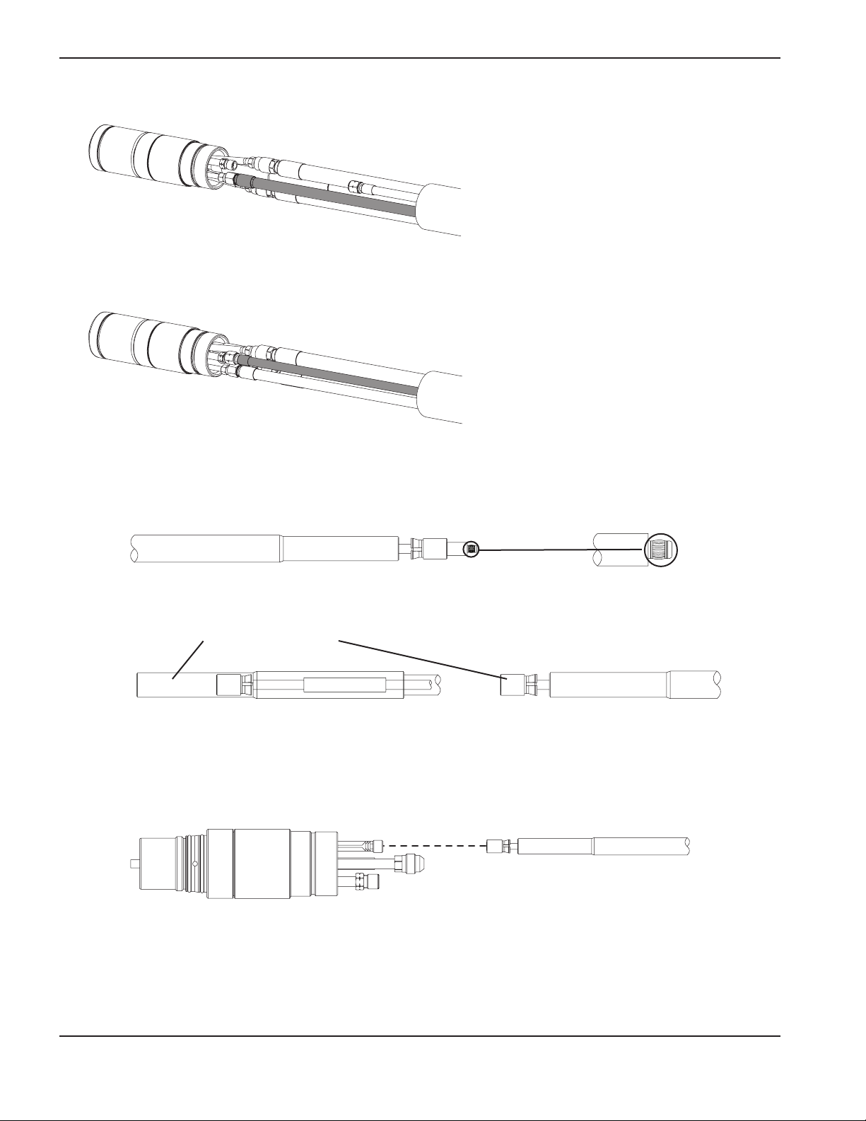
INSTALLATION
3-30 HySpeed HSD130 RHF Instruction Manual
5. Connect the shield gas hose.
6. Connect the plasma gas hose. This connection has left-hand threads.
7. Connect the pilot arc lead.
Note: Be careful not to damage or remove the small slotted metal band at the end of the pilot arc cable
7a. Pull the sleeve back until the connector is exposed.
7b. Screw the connector onto the pilot arc connection from the torch. Tighten by hand until it is firmly seated.
Page 99

INSTALLATION
HySpeed HSD130 RHF Instruction Manual 3-31
7c. Slide the sleeve forward until it clicks into place.
8. Slide the torch sleeve over the connections and screw it onto the torch body.
9. Slide the braided cover up to the torch sleeve. Push the brass collar into the torch sleeve. It is a snug fit. Make sure
the plasma and shield hoses are routed through the hole in the braided cover.
Page 100

INSTALLATION
3-32 HySpeed HSD130 RHF Instruction Manual
Work lead
7
To work table
Lower frame of work table (typical)
Work table
Power supply
Part no. Length
123662 7.5 m (25 ft)
123663 15 m (50 ft)
 Loading...