

Page 1

Duramax™ Retrofit Torch
HRT, HRTs, MRT
Operator Manual – 807190
Revision 1
Page 2

Page 3

Operator Manual
(P/N 807190)
Revision 1 – May 2011
Hypertherm, Inc.
Hanover, NH USA
www.hypertherm.com
email: info@hypertherm.com
© 2011 Hypertherm, Inc.
All Rights Reserved
Hypertherm, Powermax, and Duramax are trademarks of Hypertherm, Inc.
and may be registered in the United States and/or other countries.
Duramax™ Retrofit Torch
HRT, HRTs, MRT
Page 4

Hypertherm, Inc.
Etna Road, P.O. Box 5010
Hanover, NH 03755 USA
603-643-3441 Tel (Main Office)
603-643-5352 Fax (All Departments)
info@hypertherm.com (Main Office Email)
800-643-9878 Tel (Technical Service)
technical.service@hypertherm.com (Technical Service Email)
800-737-2978 Tel (Customer Service)
customer.service@hypertherm.com (Customer Service Email)
Hypertherm Automation
5 Technology Drive, Suite 300
West Lebanon, NH 03784 USA
603-298-7970 Tel
603-298-7977 Fax
Hypertherm Plasmatechnik GmbH
Technologiepark Hanau
Rodenbacher Chaussee 6
D-63457 Hanau-Wolfgang, Deutschland
49 6181 58 2100 Tel
49 6181 58 2134 Fax
49 6181 58 2123 (Technical Service)
Hypertherm (S) Pte Ltd.
82 Genting Lane
Media Centre
Annexe Block #A01-01
Singapore 349567, Republic of Singapore
65 6841 2489 Tel
65 6841 2490 Fax
65 6841 2489 (Technical Service)
Hypertherm (Shanghai) Trading Co., Ltd.
Unit A, 5th Floor, Careri Building
432 West Huai Hai Road
Shanghai, 200052
PR China
86-21 5258 3330/1 Tel
86-21 5258 3332 Fax
Hypertherm Europe B.V.
Vaartveld 9
4704 SE
Roosendaal, Nederland
31 165 596907 Tel
31 165 596901 Fax
31 165 596908 Tel (Marketing)
31 165 596900 Tel (Technical Service)
00 800 4973 7843 Tel (Technical Service)
Hypertherm Japan Ltd.
Level 9, Edobori Center Building
2-1-1 Edobori, Nishi-ku
Osaka 550-0002 Japan
81 6 6225 1183 Tel
81 6 6225 1184 Fax
Hypertherm Brasil Ltda.
Avenida Doutor Renato de
Andrade Maia 350
Parque Renato Maia
CEP 07114-000
Guarulhos, SP Brasil
55 11 2409 2636 Tel
55 11 2408 0462 Fax
Hypertherm México, S.A. de C.V.
Avenida Toluca No. 444, Anexo 1,
Colonia Olivar de los Padres
Delegación Álvaro Obregón
México, D.F. C.P. 01780
52 55 5681 8109 Tel
52 55 5683 2127 Fax
Hypertherm Korea Branch
#3904 Centum Leaders Mark B/D,
1514 Woo-dong, Haeundae-gu, Busan
Korea, 612-889
82 51 747 0358 Tel
82 51 701 0358 Fax
03/08/11
Page 5

9/10
Compliance Information EMC-1
Introduction
Hypertherm’s CE-marked equipment is built
in compliance with standard EN60974-10.
The equipment should be in stalled and used
in accordance with the information be low to
achieve elec tro mag net ic com pat i bil i ty.
The limits required by EN60974-10 may
not beadequate to com plete ly eliminate
interference whenthe affected equip ment
is in close proximity orhas a high degree of
sen sitivity. Insuch cases itmay be nec essary
to use other mea sures to furtherre duce
interference.
This cutting equipment is designed for use
onlyin an in dus tri al environment.
Installation and use
The user is responsible for installing and
usingtheplasma equipment according to the
manufacturer’s instructions. If elec tromagnet ic
disturbances are de tect ed then it shall be
the respon si bil i ty of the user to re solve the
situation withthe technical as sis tance of the
man u fac tur er. Insome cases this remedial
action may be as sim ple as earthing the
cuttingcircuit, see Earthingof Workpiece.
Inother cas es it could involve constructing an
electromag net ic screen enclosing the pow er
source and the work complete with associated
input filters. In all cases elec tro mag net ic
disturbanc es must be reduced to the point
where they are no longer trou ble some.
Assessment of area
Before installing the equipment the user
shall make an assessment of po ten tial
electromagnet ic problems in the sur round ing
area. The following shall be taken into account:
a. Other supply cables, control cables,
signalling and telephone ca bles; above,
below and adjacent to the cutting equipment.
b. Radio and television transmitters and
receivers.
c. Computer and other control equip ment.
d. Safety critical equipment, for example
guarding of industrial equipment.
e. Health of the people around, for example the
use of pacemakers and hear ing aids.
f. Equipment used for calibration or
measurement.
g. Immunity of other equipment in the
environment. User shall ensure that other
equipment being used in the environment
is com pat i ble. This may require ad di tion al
protection measures.
h. Time of day that cutting or other ac tiv i ties
are to be carried out.
The size of the sur round ing area to be
considered will depend on the structure of
the building and other activities that are taking
place. The surrounding area may ex tend
beyond the bound aries of the pre mises.
Methods of reducing
emissions
Mains supply
Cutting equipment must be con nect ed to the
mains supply according to the man u fac tur er’s
recom men da tions. If in ter fer ence occurs, it may
ELECTROMAGNETIC COMPATIBILITY EMC
Page 6

ELECTROMAGNETIC COMPATIBILITY EMC
9/10
EMC-2 Compliance Information
be necessary to take addi tional precautions
such as fil ter ing of the mains supply.
Consideration should be given to shield ing the
supply cable of per ma nent ly installed cutting
equip ment, in metallic conduit or equiv a lent.
Shielding should beelec tri cal ly continuous
through out its length. The shielding should
becon nect ed to the cutting mains supply
so that good electrical contact is maintained
between the conduit and the cutting pow er
source enclosure.
Maintenance of cutting equipment
The cutting equipment must be rou tine ly
maintained according to the man u fac tur er’s
recom men da tions. All ac cess and service doors
and covers should be closed and properly
fastened when the cutting equip ment is in
operation. The cutting equipment should not be
modified in any way except as set forth in and
in accordance with the manufacturer’s written
instructions. For example, the spark gaps of
arc striking and sta bi liz ing devices should be
adjusted and maintained according to the
manu fac tur er’s recommendations.
Cutting cables
The cutting cables should be kept as short
aspossible and should be po si tioned close
together, running at or close to the floor level.
Equipotential bonding
Bonding of all metallic components in the
cutting installation and adjacent to it should
be considered. However, metallic com po nents
bonded to the workpiece will increase the risk
that the op er a tor could receive a shock by
touch ing these metallic compo nents and the
electrode (nozzle for laser heads) at the same
time. The op er a tor should be in su lat ed from all
such bonded metallic components.
Earthing of workpiece
Where the workpiece is not bonded to earth
for electrical safety, nor connected to earth
because of its size and position, for example, ship’s hull or building steel work, a
con nec tion bonding the work piece to earth
may reduce emis sions in some, but not all
instances. Careshould be takento prevent the
earthing ofthe work piece increasing the risk
of injury to users, or damage to other elec tri cal
equipment. Where necessary, the con nec tion
of the workpiece to earth should be made by
a direct connection to the work piece, but in
some countries where direct connection is not
permitted, the bonding should be achieved by
suit able capacitances se lect ed according to
national regulations.
Note: the cutting circuit may or may not
be earthed for safety reasons. Changing
the earthing arrangements should only be
authorized by a person who is com pe tent to
assess whether the chang es will in crease the
risk of injury, for example, by al low ing parallel
cutting cur rent return paths which may damage
the earth cir cuits of other equipment. Further
guid ance is provided in IEC 60974-9, Arc
Welding Equip ment, Part 9: Installation and
Use.
Screening and shielding
Selective screening and shielding of other
cables and equipment in the surrounding
area may alleviate problems of in ter ference.
Screening of the entire plas ma cutting
installation may be con sid ered for special
applications.
Page 7

9/10
Compliance Information W-1
Attention
Genuine Hypertherm parts are the factoryrecommended replacement parts for your
Hypertherm system. Any damage or injury
caused by the use of other than genuine
Hypertherm parts may not be covered by the
Hypertherm warranty, and will constitute misuse
of the Hypertherm Product.
You are solely responsible for the safe use of
the Product. Hypertherm does not and cannot
make any guarantee or warranty regarding the
safe use of the product in your environment.
General
Hypertherm, Inc. warrants that its Products
shall be free from defects in materials and
workmanship for the specific periods of time
set forth herein and as follows: if Hypertherm
is notified of a defect (i) with respect to the
power supply within a period of two (2) years
from the date of its delivery to you, with the
exception of Powermax brand power supplies,
which shall be within a period of three (3) years
from the date of delivery to you, and (ii) with
respect to the torch and leads within a period
of one (1) year from its date of delivery to you,
and with respect to torch lifter assemblies
within a period of one (1) year from its date of
delivery to you, and with respect to laser heads
within a period of one (1) year from its date of
delivery to you, and with respect to Automation
products one (1) year from its date of delivery
to you, with the exception of the EDGE Pro
CNC and ArcGlide THC, which shall be within
a period of two (2) years from the date of
delivery to you.
This warranty shall not apply to any Powermax
brand power supplies that have been used with
phase converters. In addition, Hypertherm does
not warranty systems that have been damaged
as a result of poor power quality, whether from
phase converters or incoming line power. This
warranty shall not apply to any Product which
has been incorrectly installed, modified, or
otherwise damaged.
Hypertherm provides repair, replacement or
adjustment of the Product as the sole and
exclusive remedy, if and only if the warranty
set forth herein properly is invoked and
applies. Hypertherm, at its sole option, shall
repair, replace, or adjust, free of charge, any
defective Products covered by this warranty
which shall be returned with Hypertherm’s prior
authorization (which shall not be unreasonably
withheld), properly packed, to Hypertherm’s
place of business in Hanover, New Hampshire,
or to an authorized Hypertherm repair facility,
all costs, insurance and freight pre paid by
the customer. Hypertherm shall not be liable
for any repairs, replacement, or adjustments
of Products covered by this warranty, except
those made pursuant to this paragraph and
with Hypertherm’s prior written consent.
The warranty set forth above is exclusive and is
in lieu of all other warranties, express, implied,
statutory, or otherwise with respect to the
Products or as to the results which may be
obtained therefrom, and all implied warranties
or conditions of quality or of merchantability
or fitness for a particular purpose or against
infringement. The foregoing shall constitute the
sole and exclusive remedy for any breach by
Hypertherm of its warranty.
WARRANTY
Page 8

WARRANTY
9/10
W-2 Compliance Information
WARRANTY
Distributors/OEMs may offer different or
additional warranties, but Distributors/OEMs
are not authorized to give any additional
warranty protection to you or make any
representation to you purporting to be binding
upon Hypertherm.
Distributors/OEMs may offer different or
additional warranties, but Distributors/OEMs
are not authorized to give any additional
warranty protection to you or make any
representation to you purporting to be binding
upon Hypertherm.
Patent indemnity
Except only in cases of products not
manufactured by Hypertherm or manufactured
by a person other than Hypertherm not in strict
conformity with Hypertherm’s specifications
and in cases of designs, processes, formulae,
or combinations not developed or purported
to be developed by Hypertherm, Hypertherm
will have the right to defend or settle, at
its own expense, any suit or proceeding
brought against you alleging that the use
of the Hypertherm product, alone and not
in combination with any other product not
supplied by Hypertherm, infringes any patent
of any third party. You shall notify Hypertherm
promptly upon learning of any action or
threatened action in connection with any
such alleged infringement (and in any event
no longer than fourteen (14) days after
learning of any action or threat of action), and
Hypertherm’s obligation to defend shall be
conditioned upon Hypertherm’s sole control
of, and the indemnified party’s cooperation and
assistance in, the defense of the claim.
Limitation of liability
In no event shall Hypertherm be liable to
any person or entity for any incidental,
consequential direct, indirect, punitive
or exemplary damages (including but
not limited to lost profits) regardless of
whether such liability is based on breach
of contract, tort, strict liability, breach of
warranty, failure of essential purpose,
or otherwise, and even if advised of the
possibility of such damages.
National and local codes
National and local codes governing plumbing
and electrical installation shall take precedence
over any instructions contained in this manual.
In no event shall Hypertherm be liable for injury
to persons or property damage by reason of
any code violation or poor work practices.
Liability cap
In no event shall Hypertherm’s liability,
if any, whether such liability is based on
breach of contract, tort, strict liability,
breach of warranties, failure of essential
purpose or otherwise, for any claim,
action, suit or proceeding (whether in
court, arbitration, regulatory proceeding
or otherwise) arising out of or relating
to the use of the Products exceed in
the aggregate the amount paid for the
Products that gave rise to such claim.
Insurance
At all times you will have and maintain
insurance in such quantities and types, and
with coverage sufficient and appropriate to
defend and to hold Hypertherm harmless in the
event of any cause of action arising from the
use of the products.
Page 9

WARRANTY
9/10
Compliance Information W-3
Transfer of rights
You may transfer any remaining rights you may
have hereunder only in connection with the
sale of all or substantially all of your assets or
capital stock to a successor in interest who
agrees to be bound by all of the terms and
conditions of this Warranty. Within thirty (30)
days before any such transfer occurs, you
agree to notify in writing Hypertherm, which
reserves the right of approval. Should you
fail timely to notify Hypertherm and seek its
approval as set forth herein, the Warranty set
forth herein shall be null and void and you will
have no further recourse against Hypertherm
under the Warranty or otherwise.
Page 10

WARRANTY
9/10
W-4 Compliance Information
Page 11

TABLE OF CONTENTS
Duramax Retrofit Torch Operator Manual xi
Electromagnetic compatibility .................................................................................................................. EMC-1
Warranty............................................................................................................................................................. W-1
Section 1
Specifications
Component weights .......................................................................................................................................... 1-2
Duramax HRT hand torch dimensions .......................................................................................................... 1-2
Duramax HRTs hand torch dimensions ........................................................................................................1-2
Duramax MRT full-length machine torch dimensions ................................................................................ 1-3
Duramax MRT without positioning sleeve (mini torch) .............................................................................. 1-3
Section 2
Torch Setup
Introduction ......................................................................................................................................................... 2-2
Consumable life .................................................................................................................................................. 2-2
Hand torch setup ............................................................................................................................................... 2-3
Choose the hand torch consumables ................................................................................................ 2-3
Hand torch consumables ...................................................................................................................... 2-4
Install the hand torch consumables ..................................................................................................... 2-5
Machine torch setup.......................................................................................................................................... 2-6
Converting a Duramax retrofit machine torch into a mini torch .................................................... 2-7
Mount the torch ........................................................................................................................................ 2-9
Choose the machine torch consumables ........................................................................................2-12
Machine torch consumables ...............................................................................................................2-12
Install the machine torch consumables ............................................................................................2-15
Aligning the torch ..................................................................................................................................2-15
Torch installation ..............................................................................................................................................2-16
Section 3
Operation
Using the cut charts .......................................................................................................................................... 3-3
Estimated kerf-width compensation .................................................................................................... 3-3
100 amp mechanized shielded cutting for Powermax1650.......................................................... 3-6
85 amp mechanized shielded cutting for Powermax1650 ............................................................ 3-8
80 amp mechanized shielded cutting for Powermax1250/1650 ..............................................3-12
65 amp mechanized shielded cutting for Powermax1250/1650 ..............................................3-14
60 amp mechanized shielded cutting for Powermax1000/1250/1650 ...................................3-18
Page 12

TABLE OF CONTENTS
xii Duramax Retrofit Torch Operator Manual
45 amp mechanized shielded cutting for Powermax1000/1250/1650 ...................................3-20
100 amp mechanized unshielded cutting for Powermax1650 ...................................................3-24
85 amp mechanized unshielded cutting for Powermax1650......................................................3-26
65 amp mechanized unshielded cutting for Powermax1250/1650 ..........................................3-30
45 amp mechanized unshielded cutting for Powermax1000/1250/1650 ..............................3-34
FineCut® consumables for Powermax1000/1250/1650 ............................................................3-38
Using the hand torch .......................................................................................................................................3-41
Operate the safety trigger ...................................................................................................................3-41
Hand torch cutting hints ......................................................................................................................3-42
Start a cut from the edge of the workpiece.....................................................................................3-43
Pierce a workpiece ................................................................................................................................3-44
Gouge a workpiece ..............................................................................................................................3-45
Common hand-cutting faults ..............................................................................................................3-48
Using the machine torch ................................................................................................................................3-49
Ensure the torch and table are set up correctly .............................................................................3-49
Understand and optimize cut quality .................................................................................................3-49
To pierce a workpiece using the machine torch ............................................................................3-52
Common machine-cutting faults ........................................................................................................3-52
Section 4
Maintenance and parts
Perform routine maintenance .......................................................................................................................... 4-2
Inspect the consumables ................................................................................................................................. 4-3
Hand torch replacement parts ........................................................................................................................ 4-4
Machine torch replacement parts .................................................................................................................. 4-6
Accessory parts.................................................................................................................................................. 4-7
Page 13

Duramax Retrofit Torch Operator Manual 1-1
Section 1
SPECIFICATIONS
In this section:
Component weights .......................................................................................................................................... 1-2
Duramax HRT hand torch dimensions .......................................................................................................... 1-2
Duramax HRTs hand torch dimensions ........................................................................................................1-2
Duramax MRT full-length machine torch dimensions ................................................................................ 1-3
Duramax MRT without positioning sleeve (mini torch) .............................................................................. 1-3
Page 14

SPECIFICATIONS
1-2 Duramax Retrofit Torch Operator Manual
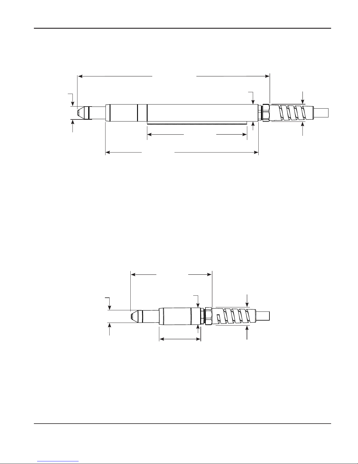
Duramax HRT hand torch dimensions
Duramax HRTs hand torch dimensions
9.9 in (25.2 cm)
3.8 in
(9.8 cm)
75°
angle
2.6 in
(6.6 cm)
1.0 in
(2.5 cm)
Component weights
Torch type Weight – lbs (kg)
Hand torch 25 ft (7.6 m) 7.1 (3.2)
Hand torch 50 ft (15 m) 12.5 (5.7)
Machine torch 25 ft (7.6 m) 7.6 (3.4)
Machine torch 50 ft (15 m) 13.2 (6.0)
10.2 in (25.9 cm)
1.9 in
(4.7 cm)
15°
angle
2.6 in
(6.6 cm)
1.0 in
(2.5 cm)
Page 15
SPECIFICATIONS
Duramax Retrofit Torch Operator Manual 1-3
Duramax MRT full-length machine torch dimensions
15.6 in
(39.6 cm)
1.0 in
(2.5 cm)
1.4 in (3.6 cm) outer
dimension, 1.3 in
(3.3cm) flat sides
12.3 in
(31.3 cm)
8.1 in
(20.6 cm)
1.4 in
(3.5 cm)
1.0 in
(2.5 cm)
1.4 in (3.6 cm) outer
dimension, 1.3 in
(3.3cm) flat sides
1.4 in
(3.5 cm)
Duramax MRT without positioning sleeve (mini torch)
6.6 in
(16.8 cm)
3.3 in
(8.4 cm)
Page 16

SPECIFICATIONS
1-4 Duramax Retrofit Torch Operator Manual
Page 17

Duramax Retrofit Torch Operator Manual 2-1
Section 2
TORCH SETUP
In this section:
Introduction ......................................................................................................................................................... 2-2
Consumable life .................................................................................................................................................. 2-2
Hand torch setup ............................................................................................................................................... 2-3
Choose the hand torch consumables ................................................................................................ 2-3
Hand torch consumables ...................................................................................................................... 2-4
Install the hand torch consumables ..................................................................................................... 2-5
Machine torch setup.......................................................................................................................................... 2-6
Converting a Duramax retrofit machine torch into a mini torch .................................................... 2-7
Mount the torch ........................................................................................................................................ 2-9
Choose the machine torch consumables ........................................................................................2-12
Machine torch consumables ...............................................................................................................2-12
Install the machine torch consumables ............................................................................................2-15
Aligning the torch ..................................................................................................................................2-15
Torch installation ..............................................................................................................................................2-16
Page 18

TORCH SETUP
2-2 Duramax Retrofit Torch Operator Manual
Introduction
Duramax™ series handheld and machine retrofit torches are available for the Powermax1000,
Powermax1250, and Powermax1650 systems. The ETR (Easy Torch Removal)™ quick-disconnect
system makes it easy to remove the torch for transport or to switch from one torch to the other if
your applications require the use of different torches. The torches are cooled by ambient air and do
not require special cooling procedures.
This section explains how to setup your torch and choose the appropriate consumables for the job.
Consumable life
How often you need to change the consumables on your retrofit torch will depend on a number of
factors:
• Thickness of the material – the thicker the material being cut, the more often consumables
need to be changed.
• Average length of cut – the longer the average cut, the more often consumables need to
be changed.
• Type of cutting – handheld cutting will require more consumable changes than machine
cutting.
• Air quality – the presence of oil, moisture, or other contaminants will reduce consumable
life.
• Piercing / edge starting – piercing the metal causes more consumable wear then starting
cuts from the edge of the metal.
• Proper torch-to-work distance – when gouging or cutting with unshielded consumables,
maintaining proper torch-to-work distance will result in better consumable life.
• Proper pierce height – maintaining proper pierce height will result in better consumable
life.
• Cutting in “continuous pilot arc” mode or normal cutting mode – cutting with a continuous
pilot arc causes more consumable wear than cutting in normal cutting mode.
You will find more information about proper cutting techniques in Section 3, Operation.
Page 19

TORCH SETUP
Duramax Retrofit Torch Operator Manual 2-3
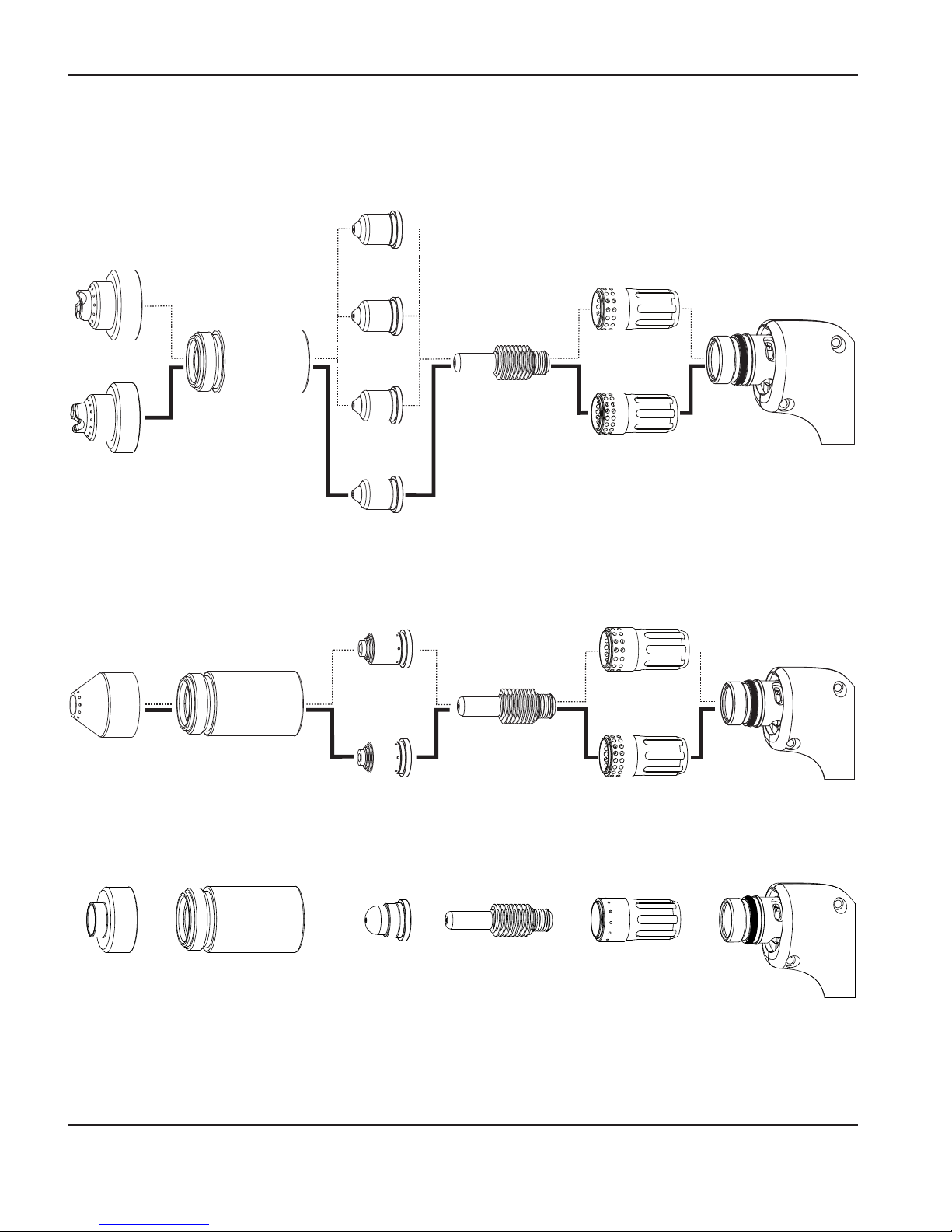
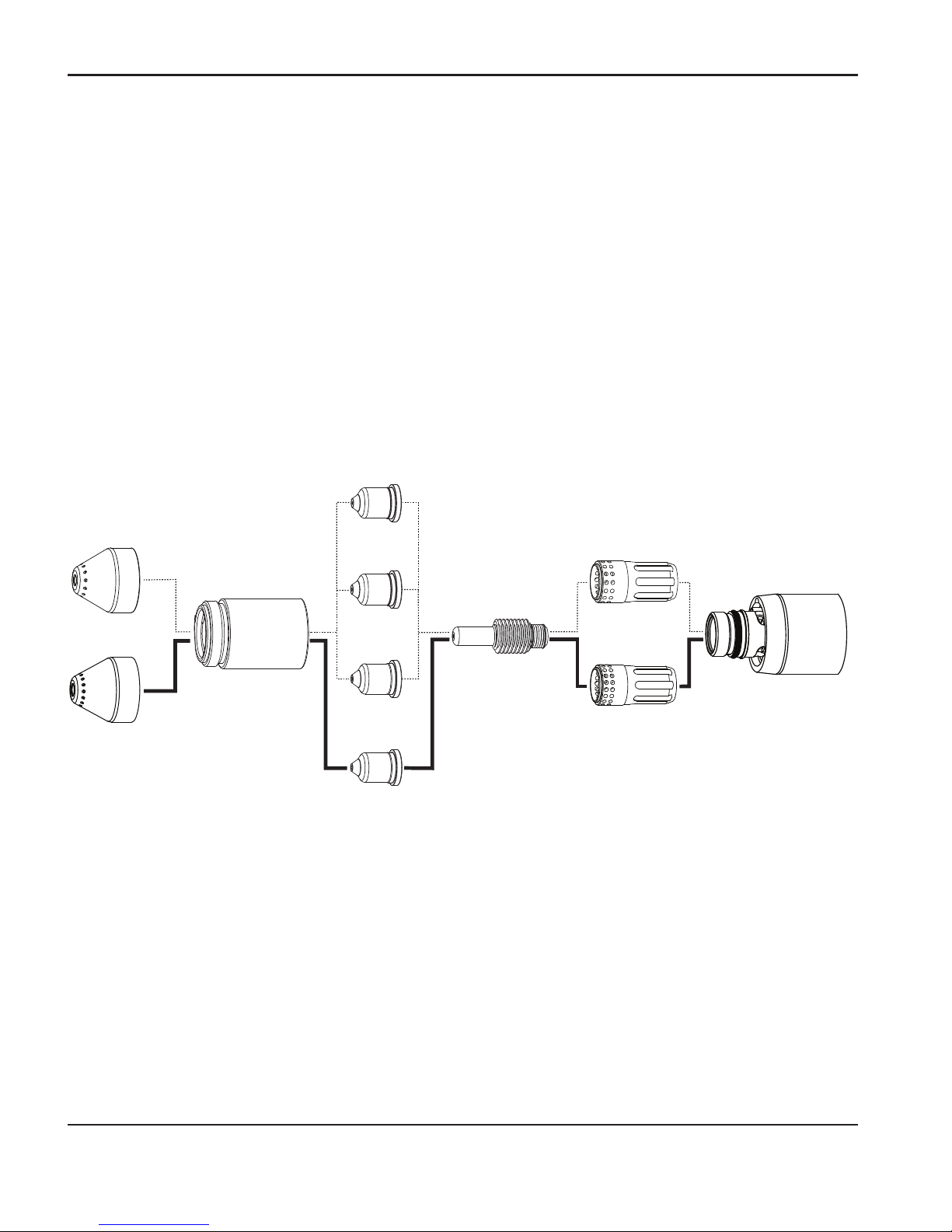
Choose the hand torch consumables
Duramax retrofit torches are shipped with a full set of cutting consumables pre-installed.
Hypertherm also includes spare cutting electrodes, nozzles, and gouging consumables in the
consumables box, for handheld torches.
Consumables for handheld cutting are shown on the next page. Notice that the retaining cap and
electrode are the same for cutting, gouging, and FineCut® applications. Only the shield, nozzle,
and swirl ring are different.
For the best cut quality on thin materials, you may prefer to use FineCut consumables, or use a
45A nozzle and reduce the current setting to 45 amps.
Consumables
Consumables
Safety trigger
Safety trigger
Hand torch setup
Duramax HRT
Duramax HRTs
Page 20
TORCH SETUP
2-4 Duramax Retrofit Torch Operator Manual
6
5
A
4
5
A
8
5
A
1
0
0
A
Hand torch consumables
Drag-cutting consumables: Powermax1000/1250/1650
Gouging consumables: Powermax1000/1250/1650
FineCut
®
consumables: Powermax1000/1250/1650
220854
Retaining cap
220947
Swirl ring
220842
Electrode
220931
Shield
220930
Nozzle
Powermax1000 – Use 45-65 A consumables
Powermax1250 – Use 45-85 A consumables
Powermax1650 – Use 45-100 A consumables
220857
Swirl ring
220994
Swirl ring
220842
Electrode
220941
Nozzle
220819
Nozzle
220816
Nozzle
220990
Nozzle
220854
Retaining cap
220818
Shield
220992
Shield
1
0
0
A
6
5
A
8
5
A
220857
Swirl ring
220994
Swirl ring
220842
Electrode
220797
Nozzle
220991
Nozzle
220854
Retaining cap
220798
Shield
Page 21
TORCH SETUP
Duramax Retrofit Torch Operator Manual 2-5
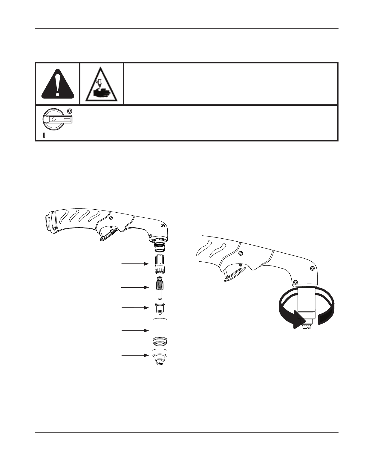
Install the hand torch consumables
To operate the hand torch, a complete set of consumable parts must be installed: shield, retaining
cap, nozzle, electrode, and swirl ring.
With the power switch in the OFF (O) position, install the torch consumables asshown below.
Retaining cap
Nozzle
Electrode
Swirl ring
Shield
WARNING
INSTANTON TORCHES
PLASMA ARC CAN CAUSE INJURY AND BURNS
The plasma arc comes on im me di ate ly when the torch trigger is
activated. Make sure the power is OFF before changing consumables.
Page 22
TORCH SETUP
2-6 Duramax Retrofit Torch Operator Manual
Machine torch setup
Before using either style of machine torch, you must:
• Mount the torch on your cutting table or other equipment.
• Choose and install the consumables.
• Align the torch.
• Attach the torch lead to the power supply.
• Set up the power supply for remote starting with either the remote-start pendant or a
machine interface cable.
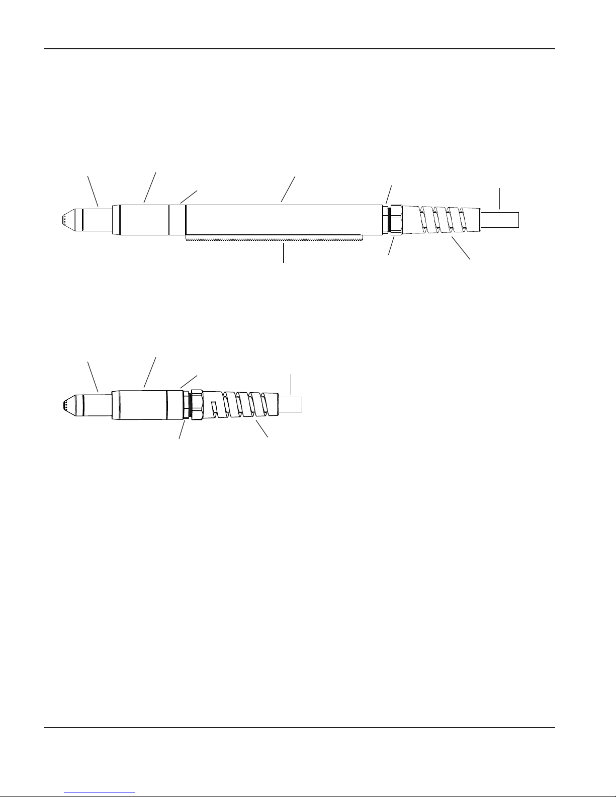
Consumables
Consumables
Mounting
sleeve
Mounting
sleeve
Coupler
Coupler
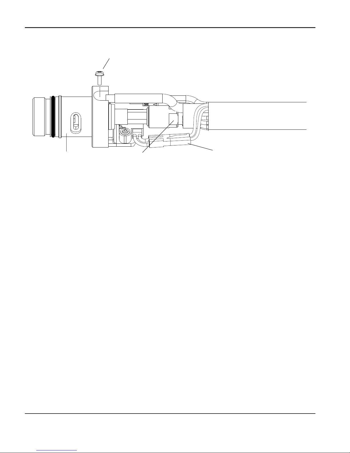
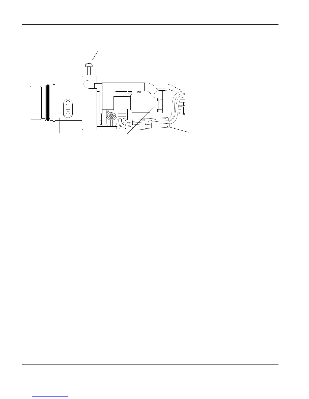
Gear rack Strain relief body
Strain relief body
Strain relief nut
Main strain
relief nut
Strain relief nut
Torch lead
Torch lead
Positioning sleeve
Duramax MRT
Duramax MRT without positioning sleeve (mini torch)
Page 23

TORCH SETUP
Duramax Retrofit Torch Operator Manual 2-7
Converting a Duramax retrofit machine torch into a mini torch
You can convert a full-length machine torch to a mini-machine torch by removing the positioning
sleeve.
Note: If you are converting a full-length machine torch to a mini-machine torch and
mounting the torch at the same time, skip this section and follow the instructions in
“Mount the torch” on page 2-9.
Refer to the figures in the section “Machine torch setup” on page 2-6 and follow these instructions.
Note: While disconnecting and reconnecting the torch parts, maintain the same orientation
between the torch head and torch lead. Twisting the torch head in relation to the
torch lead can cause damage.
1. Disconnect the torch lead from the power supply and remove the consumables from the torch.
2. Unscrew the strain relief body from the strain relief nut and slide the strain relief body back
along the torch lead.
3. Unscrew the strain relief nut from the positioning sleeve and slide the nut back along the torch
lead.
4. Unscrew the positioning sleeve from the coupler.
5. Unscrew the coupler from the mounting sleeve.
6. Remove the three screws from the consumables end of the mounting sleeve and slide the
mounting sleeve off the front of the torch body.
Page 24
TORCH SETUP
2-8 Duramax Retrofit Torch Operator Manual
7. Disconnect the wire connector for the cap-sensor switch.
8. Use a #2 Phillips screwdriver to remove the screw that secures the torch’s pilot wire to the
torch body.
9. Use 1/4-inch and 3/8-inch wrenches, or adjustable wrenches, to loosen the nut that secures
the gas supply line to the torch lead. Set the torch body aside.
10. Slide the coupler and positioning sleeve off the front of the torch lead.
11. Slide the coupler over the torch lead.
12. Reconnect the gas line to the torch lead.
13. Reattach the torch’s pilot wire to the torch body using the screw.
14. Reconnect the cap-sensor switch’s wire connector.
15. Slide the mounting sleeve over the front of the torch body. Align the slot on the front of the
mounting sleeve (next to one of the three screw holes) with the cap-sensor plunger on the
torch body.
16. Attach the mounting sleeve to the torch body using the three screws.
17. Screw the coupler into the mounting sleeve.
18. Screw the strain relief nut into the coupler.
19. Screw the strain relief body into the strain relief nut.
Gas supply line
connection
Torch head
Pilot wire
terminal screw
Wire connector for
cap-sensor switch
Page 25

TORCH SETUP
Duramax Retrofit Torch Operator Manual 2-9
Mount the torch
Depending on the type of cutting table you have, you may or may not need to disassemble the
torch to route it through the track and mount it. If your cutting table’s track is large enough for you
to thread the torch through it without removing the torch body from the lead, do so and then attach
the torch to the lifter per the manufacturer’s instructions.
Note: The Duramax machine torches can be mounted on a wide variety of X-Y tables, track
burners, pipe bevelers, and other equipment. Install the torch per the manufacturer’s
instructions and follow the instructions below for disassembly if necessary.
If you need to disassemble and reassemble the torch, refer to the figures in the section “Machine
torch setup” on page 2-6 and follow these instructions.
Note: While disconnecting and reconnecting the torch parts, maintain the same orientation
between the torch head and torch lead. Twisting the torch head in relation to the
torch lead can cause damage.
1. Disconnect the torch lead from the power supply and remove the consumables from the torch.
2. Unscrew the strain relief body from the strain relief nut and slide the strain relief body back
along the torch lead.
3. Unscrew the strain relief nut from the positioning sleeve (full-length machine torch) and slide
the nut back along the torch lead.
4. Unscrew the positioning sleeve from the coupler.
5. Unscrew the coupler from the mounting sleeve.
6. Remove the three screws from the consumables end of the mounting sleeve and slide the
mounting sleeve off the front of the torch body.
Page 26
TORCH SETUP
2-10 Duramax Retrofit Torch Operator Manual
7. Disconnect the wire connector for the cap-sensor switch.
8. Use a #2 Phillips screwdriver to remove the screw that secures the torch’s pilot wire to the
torch body.
9. Use 1/4-inch and 3/8-inch wrenches, or adjustable wrenches, to loosen the nut that secures
the gas supply line to the torch lead. Set the torch body aside.
Note: Cover the end of the gas line on the torch lead with tape to keep dirt and other
contaminants from getting in the gas line when you route the lead through the track.
10. Slide the coupler, positioning sleeve (full-length machine torch), strain relief nut, and strain
relief body off the front of the torch lead.
11. If you do not need the gear rack on a full-length machine torch, slide the gear rack from the
positioning sleeve toward the consumables end of the sleeve.
12. Route the torch lead through the cutting table’s track.
Gas supply line
connection
Torch head
Pilot wire
terminal screw
Wire connector for
cap-sensor switch
Page 27

TORCH SETUP
Duramax Retrofit Torch Operator Manual 2-11
13. Slide the strain relief body and strain relief nut over the torch lead.
14. If you are mounting a full-length machine torch, slide the positioning sleeve over the torch
head.
15. Slide the coupler over the torch lead.
16. Reconnect the gas line to the torch lead.
17. Reattach the torch’s pilot wire to the torch body using the screw.
18. Reconnect the cap-sensor switch’s wire connector.
19. Slide the mounting sleeve over the front of the torch body. Align the slot on the front of the
mounting sleeve (next to one of the three screw holes) with the cap-sensor plunger on the
torch body.
20. Attach the mounting sleeve to the torch body using the three screws.
21. Screw the coupler into the mounting sleeve.
22. If you are mounting a full-length machine torch, screw the positioning sleeve into the coupler.
23. Reconnect the strain relief nut and strain relief body.
24. Attach the torch to the lifter per the manufacturer’s instructions.
Page 28
TORCH SETUP
2-12 Duramax Retrofit Torch Operator Manual
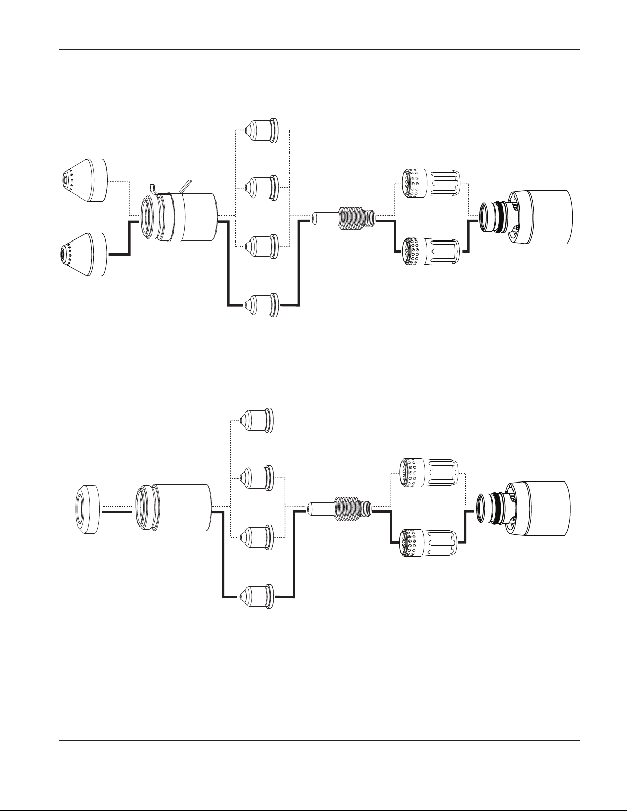
Choose the machine torch consumables
Powermax systems with the Duramax MRT retrofit torch are shipped with a complete set of
consumables. Hypertherm also includes spare electrodes and nozzles. In addition, an ohmicsensing retaining cap is available for use with shielded consumables. With shielded consumables,
the torch tip may touch the metal when cutting. With unshielded consumables, you must keep
the torch a small distance, about .08 inch (2 mm), away from the metal. Unshielded consumables
generally have a shorter life than shielded consumables.
Machine torch consumables
Mechanized shielded consumables: Powermax1000/1250/1650
6
5
A
4
5
A
8
5
A
1
0
0
A
220817
Shield
220993
Shield
220854
Retaining cap
220941
Nozzle
220819
Nozzle
220816
Nozzle
220990
Nozzle
220842
Electrode
220857
Swirl ring
220994
Swirl ring
Powermax1000 – Use 45-65 A consumables
Powermax1250 – Use 45-85 A consumables
Powermax1650 – Use 45-100 A consumables
Page 29
TORCH SETUP
Duramax Retrofit Torch Operator Manual 2-13
6
5
A
4
5
A
8
5
A
1
0
0
A
220994
Swirl ring
220993
Shield
220842
Electrode
220953
Ohmic-sensing
retaining cap
Mechanized shielded with ohmic consumables: Powermax1000/1250/1650
220941
Nozzle
220819
Nozzle
220816
Nozzle
Mechanized unshielded consumables: Powermax1000/1250/1650
220857
Swirl ring
220990
Nozzle
220817
Shield
6
5
A
4
5
A
8
5
A
1
0
0
A
220994
Swirl ring
220857
Swirl ring
220842
Electrode
220941
Nozzle
220819
Nozzle
220816
Nozzle
220990
Nozzle
220854
Retaining cap
220955
Deflector
Powermax1000 – Use 45-65 A consumables
Powermax1250 – Use 45-85 A consumables
Powermax1650 – Use 45-100 A consumables
Page 30

TORCH SETUP
2-14 Duramax Retrofit Torch Operator Manual
1
0
0
A
6
5
A
8
5
A
Gouging consumables: Powermax1000/1250/1650
220854
Retaining cap
220842
Electrode
220798
Shield
FineCut® unshielded consumables: Powermax1000/1250/1650
FineCut
®
shielded consumables: Powermax1000/1250/1650
220854
Retaining cap
220953
Retaining cap
220857
Swirl ring
220857
Swirl ring
220842
Electrode
220842
Electrode
220955
Deflector
220948
Shield
220930
Nozzle
220930
Nozzle
Powermax1000 – Use 45-65 A consumables
Powermax1250 – Use 45-85 A consumables
Powermax1650 – Use 45-100 A consumables
220857
Swirl ring
220994
Swirl ring
220797
Nozzle
220991
Nozzle
Page 31

TORCH SETUP
Duramax Retrofit Torch Operator Manual 2-15
Install the machine torch consumables
To operate the machine torch, a complete set of consumable parts must be installed: shield,
retaining cap, nozzle, electrode, and swirl ring.
With the power switch in the OFF (O) position, install the machine torch consumables in a manner
similar to the hand torch consumables. Refer to “Install the hand torch consumables” on page 2-5.
WARNING
INSTANT-ON TORCHES
PLASMA ARC CAN CAUSE INJURY AND BURNS
The plasma arc comes on im me di ate ly when the torch is activated.
Make sure the power is OFF before changing the consumables.
Aligning the torch
Mount the machine torch perpendicular to the workpiece in order to get a vertical cut. Use a
square to align the torch at 0° and 90°.
Torch
0°
90°
Page 32

TORCH SETUP
2-16 Duramax Retrofit Torch Operator Manual
Torch installation
1. Turn OFF the power.
2. Remove the power cord from the power receptacle.
3. Open the Easy Torch Removal (ETR) door and route the lead through the end cap.
_
+
4.0 5.0
5
0
60
AC
70 80
V
BAR
6.0
PSI
AMPS
3
0
40
1
00
8
0
60
OFF
ON
ETR door
End cap
Page 33

TORCH SETUP
Duramax Retrofit Torch Operator Manual 2-17
4. Align the marks on the strain relief.
5. Pull back the quick-release collar and insert
the lead’s gas fitting.
6. Slide the quick-release collar forward to lock
the gas fitting in place. Make sure that the
gas fitting is secure.
7. Make sure that the red dot on the connector
is on top, then plug in the electrical
connector.
Close the ETR door.
Quick-release collar
Page 34

TORCH SETUP
2-18 Duramax Retrofit Torch Operator Manual
Page 35

Duramax Retrofit Torch Operator Manual 3-1
Section 3
OPERATION
In this section:
Using the cut charts .......................................................................................................................................... 3-3
Estimated kerf-width compensation .................................................................................................... 3-3
100 amp mechanized shielded cutting for Powermax1650.......................................................... 3-6
85 amp mechanized shielded cutting for Powermax1650 ............................................................ 3-8
80 amp mechanized shielded cutting for Powermax1250/1650 ..............................................3-12
65 amp mechanized shielded cutting for Powermax1250/1650 ..............................................3-14
60 amp mechanized shielded cutting for Powermax1000/1250/1650 ...................................3-18
45 amp mechanized shielded cutting for Powermax1000/1250/1650 ...................................3-20
100 amp mechanized unshielded cutting for Powermax1650 ...................................................3-24
85 amp mechanized unshielded cutting for Powermax1650......................................................3-26
65 amp mechanized unshielded cutting for Powermax1250/1650 ..........................................3-30
45 amp mechanized unshielded cutting for Powermax1000/1250/1650 ..............................3-34
FineCut® consumables for Powermax1000/1250/1650 ............................................................3-38
Using the hand torch .......................................................................................................................................3-41
Operate the safety trigger ...................................................................................................................3-41
Hand torch cutting hints ......................................................................................................................3-42
Start a cut from the edge of the workpiece.....................................................................................3-43
Pierce a workpiece ................................................................................................................................3-44
Gouge a workpiece ..............................................................................................................................3-45
Common hand-cutting faults ..............................................................................................................3-48
Page 36

OPERATION
3-2 Duramax Retrofit Torch Operator Manual
Using the machine torch ................................................................................................................................3-49
Ensure the torch and table are set up correctly .............................................................................3-49
Understand and optimize cut quality .................................................................................................3-49
To pierce a workpiece using the machine torch ............................................................................3-52
Common machine-cutting faults ........................................................................................................3-52
Page 37

OPERATION
Duramax Retrofit Torch Operator Manual 3-3
Using the cut charts
The following sections provide cut charts for each set of mechanized consumables. A consumable
diagram with part numbers precedes each section.
The arc voltage increases as the consumables wear and the voltage setting should be increased to
maintain the correct Torch-to-Work Distance.
Note: Hypertherm collected the data under laboratory test conditions using new
consumables.
Estimated kerf-width compensation
The widths in the tables on the following two pages are for reference. The data is obtained with
the “Best Quality” settings. Differences between installations and material composition may cause
actual results to vary from those shown in the tables.
Page 38

OPERATION
3-4 Duramax Retrofit Torch Operator Manual
Process
Thickness (mm)
0.5 1 2 3 6 8 10 12 16 20
Mild Steel
100 A Shielded 2.0 2.1 2.2 2.2 2.3 2.7
85 A Shielded 1.7 1.8 1.9 2.0 2.2 2.4 2.6
80 A Shielded 1.7 1.7 1.8 1.8 1.8 2.0 2.3
65 A Shielded 1.6 1.6 1.8 1.9 2.0 2.2 2.3
60 A Shielded 1.4 1.4 1.6 1.6 1.7 1.8 1.9
45 A Shielded 1.1 1.1 1.4 1.5 1.7
FineCut 0.7 0.7 1.3 1.3
85 A Unshielded 1.7 1.8 1.9 2.0 2.1 2.1 2.3
65 A Unshielded 1.6 1.6 1.7 1.8 1.9 2.0
45 A Unshielded 0.5 0.9 1.3 1.3
Stainless Steel
100 A Shielded 1.9 1.9 2.0 2.1 2.2 2.3
85 A Shielded 1.6 1.8 1.9 2.1 2.3 2.4 2.5
80 A Shielded 1.7 1.7 1.8 1.8 1.9 2.1 2.2
65 A Shielded 1.4 1.5 1.8 1.9 2.0 2.2 2.4
60 A Shielded 1.5 1.5 1.6 1.7 1.8 1.8 2.0
45 A Shielded 0.9 1.1 1.5 1.6 1.8
FineCut 0.6 0.6 1.4 1.5
85 A Unshielded 1.7 1.7 1.8 1.9 2.1 2.2 2.4
65 A Unshielded 1.6 1.6 1.8 1.8 1.9 2.0
45 A Unshielded 0.5 1.0 1.3 1.5 1.5
Aluminum
100 A Shielded 2.1 2.1 2.1 2.1 2.1 2.3
85 A Shielded 2.0 1.9 2.0 2.1 2.2 2.4 2.6
80 A Shielded 1.7 1.7 1.7 1.8 1.8 1.8
65 A Shielded 1.9 1.9 1.9 2.0 2.1 2.3 2.5
60 A Shielded 1.5 1.5 1.5 1.5 1.6 1.6 1.6
45 A Shielded 1.5 1.5 1.6 1.5
85 A Unshielded 1.9 1.9 1.9 2.0 2.0 2.1 2.2
65 A Unshielded 1.8 1.8 1.8 1.8 1.9 2.0
45 A Unshielded 1.6 1.5 1.4 1.5
Estimated kerf-width compensation – Metric (mm)
Page 39

OPERATION
Duramax Retrofit Torch Operator Manual 3-5
Process
Thickness (inches)
22 GA 18 GA 14 GA 10 GA 3/16 1/4 3/8 1/2 5/8 3/4
Mild Steel
100 A Shielded 0.079 0.085 0.085 0.089 0.107
85 A Shielded 0.068 0.071 0.073 0.078 0.090 0.095 0.100
80 A Shielded 0.068 0.068 0.071 0.073 0.078 0.088
65 A Shielded 0.062 0.065 0.068 0.070 0.076 0.088 0.090 0.091
60 A Shielded 0.055 0.057 0.060 0.063 0.067 0.071 0.076 0.084
45 A Shielded 0.035 0.054 0.055 0.061 0.065 0.066
FineCut 0.024 0.043 0.049 0.051
85 A Unshielded 0.070 0.073 0.075 0.080 0.085 0.090
65 A Unshielded 0.062 0.064 0.066 0.068 0.075 0.081
45 A Unshielded 0.020 0.050 0.051 0.054 0.057 0.059
Stainless Steel
100 A Shielded 0.074 0.079 0.083 0.087 0.090
85 A Shielded 0.068 0.071 0.073 0.078 0.090 0.095 0.100
80 A Shielded 0.066 0.072 0.077 0.082 0.088
65 A Shielded 0.062 0.065 0.068 0.070 0.076 0.088 0.090 0.091
60 A Shielded 0.065 0.069 0.073 0.080 0.088
45 A Shielded 0.035 0.054 0.055 0.061 0.065 0.066
FineCut 0.024 0.043 0.049 0.051
85 A Unshielded 0.070 0.073 0.075 0.080 0.085 0.090
65 A Unshielded 0.062 0.064 0.066 0.068 0.075 0.081
45 A Unshielded 0.020 0.050 0.051 0.054 0.057 0.059
Aluminum
1/32 1/16 1/8 3/16 1/4 3/8 1/2 5/8 3/4
100 A Shielded 0.083 0.085 0.080 0.084 0.089
85 A Shielded 0.080 0.078 0.075 0.080 0.090 0.095 0.100
80 A Shielded 0.069 0.065 0.072 0.069 0.075
65 A Shielded 0.073 0.074 0.075 0.076 0.083 0.091 0.100
60 A Shielded 0.064 0.061 0.057 0.061 0.063 0.065
45 A Shielded 0.059 0.061 0.065 0.060
85 A Unshielded 0.075 0.075 0.075 0.080 0.082 0.088
65 A Unshielded 0.070 0.070 0.070 0.070 0.072 0.079
45 A Unshielded 0.062 0.058 0.057 0.061
Estimated kerf-width compensation – English (inches)
Page 40

OPERATION
3-6 Duramax Retrofit Torch Operator Manual
100 amp mechanized shielded cutting for Powermax1650
1
0
0
A
1
0
0
A
220993
Shield
220993
Shield
220854
Retaining cap
220994
Swirl ring
220994
Swirl ring
220842
Electrode
220842
Electrode
220953
Ohmic-sensing
retaining cap
220990
Nozzle
220990
Nozzle
• Recommended cut speeds are a good starting point for finding the best quality cut (best
angle, least dross, and best cut-surface finish). Adjust the speed for your application and
table to obtain the desired cut quality.
• Maximum cut speeds are the fastest speeds possible to cut material without regard to cut
quality.
Page 41

OPERATION
Duramax Retrofit Torch Operator Manual 3-7
Arc
current
Arc
voltage
Pierce
delay
Material thickness
Recommended cut
speed
Maximum cut speed
in mm ipm mm/min ipm mm/min
100
153 0.5 1/4 6.4 135 3429 208 5283
155 0.5 3/8 9.5 77 1955 119 3022
159 1.0 1/2 12.7 57 1447 88 2235
160 1.0 5/8 15.9 40 1016 61 1549
161 1.5 3/4 19.0 26 660 47 1193
163
NA
1 25.4 18 457 28 711
167 1 1/4 31.8 12 305 19 482
Arc
current
Arc
voltage
Pierce
delay
Material thickness
Recommended cut
speed
Maximum cut speed
in mm ipm mm/min ipm mm/min
100
154 0.5 1/4 6.4 164 4165 253 6426
157 0.5 3/8 9.5 92 2336 142 3606
160 1.0 1/2 12.7 70 1778 108 2743
161 1.0 5/8 15.9 50 1270 77 1955
162 1,5 3/4 19.0 33 838 57 1447
165 NA 1 25.4 21 533 33 838
Mild steel
Stainless steel
Aluminum
Arc
current
Arc
voltage
Pierce
delay
Material thickness
Recommended cut
speed
Maximum cut speed
in mm ipm mm/min ipm mm/min
100
154 0.5 1/4 6.4 150 3810 231 5867
156 0.5 3/8 9.5 79 2006 122 3099
161 1.0 1/2 12.7 52 1320 79 2006
162 1.0 5/8 15.9 34 863 52 1320
164 1.5 3/4 19.0 25 635 39 990
166
NA
1 25.4 15 381 23 584
169 1 1/4 31.8 9 228 14 355
Note: Torch-to-work dis tance for the following cut chart is 1/8 in (3.2 mm) for all cuts.
Page 42

OPERATION
3-8 Duramax Retrofit Torch Operator Manual
220817
Shield
220817
Shield
220854
Retaining cap
220857
Swirl ring
220857
Swirl ring
220842
Electrode
220842
Electrode
220953
Ohmic-sensing
retaining cap
85 amp mechanized shielded cutting for Powermax1650
220816
Nozzle
220816
Nozzle
8
5
A
8
5
A
• Best Quality Settings (cut speed and voltage) — Settings that provide the starting point
for finding the best cut quality (best angle, least dross, best cut-surface finish). Adjust the
speed for your application and table to obtain the desired result.
• Production Settings (cut speed and voltage) — 80% of the maximum speed ratings. These
speeds result in the greatest number of cut parts, but not necessarily the best possible cut
quality.
Page 43

OPERATION
Duramax Retrofit Torch Operator Manual 3-9
85 A Shielded
Mild Steel
Metric
Material
Thickness
Torch-
to-Work
Distance
Initial Pierce
Height
Pierce
Delay
Time
Best Quality Settings Production Settings
Cut
Speed
Voltage
Cut
Speed
Voltage
mm mm mm % seconds mm/min Volts mm/min Volts
3
1.5
3.8 250
0.1 6800 122 9200 120
4 0.2 5650 122 7300 122
6
0.5
3600 123 4400 125
8 2500 125 3100 127
10 1680 127 2070 128
12
4.5 300
0.7 1280 130 1600 130
16 1.0 870 134 930 133
20 6.0 400 1.5 570 137 680 136
25
Edge Start
350 142 450 141
30 200 146 300 144
English
Material
Thickness
Torch-
to-Work
Distance
Initial Pierce
Height
Pierce
Delay
Time
Best Quality Settings Production Settings
Cut
Speed
Voltage
Cut
Speed
Voltage
in in in % seconds ipm Volts ipm Volts
10 GA
0.06
0.15 250
0.0 250 122 336 121
3/16 0.2 185 123 220 123
1/4
0.5
130 123 160 126
3/8 70 126 86 127
1/2
0.18 300
45 131 56 131
5/8 1.0 35 134 37 133
3/4 0.24 400 1.5 24 136 29 135
7/8
Edge Start
19 139 22 138
1 13 142 17 141
1-1/8 9 145 13 143
1-1/4 7 148 10 146
Page 44

OPERATION
3-10 Duramax Retrofit Torch Operator Manual
85 A Shielded
Stainless Steel
Metric
Material
Thickness
Torch-
to-Work
Distance
Initial Pierce
Height
Pierce
Delay
Time
Best Quality Settings Production Settings
Cut
Speed
Voltage
Cut
Speed
Voltage
mm mm mm % seconds mm/min Volts mm/min Volts
3
1.5
3.8 250
0.1 7500 122 9200 120
4 0.2 6100 122 7500 120
6
0.5
3700 122 4600 122
8 2450 124 3050 124
10
4.5 300
1550 127 1900 126
12 0.7 1100 131 1400 130
16 1.0 700 135 760 134
20
Edge Start
480 138 570 137
25 300 143 370 141
English
Material
Thickness
Torch-
to-Work
Distance
Initial Pierce
Height
Pierce
Delay
Time
Best Quality Settings Production Settings
Cut
Speed
Voltage
Cut
Speed
Voltage
in in in % seconds ipm Volts ipm Volts
10 GA
0.06
0.15 250
0.2
275 122 336 120
3/16 200 122 240 121
1/4
0.5
130 122 164 122
3/8 65 126 80 125
1/2
0.18 300
36 132 48 131
5/8 1.0 28 135 30 134
3/4
Edge Start
20 137 24 136
7/8 16 140 19 139
1 11 143 14 141
Page 45

OPERATION
Duramax Retrofit Torch Operator Manual 3-11
85 A Shielded
Aluminum
Metric
Material
Thickness
Torch-
to-Work
Distance
Initial Pierce
Height
Pierce
Delay
Time
Best Quality Settings Production Settings
Cut
Speed
Voltage
Cut
Speed
Voltage
mm mm mm % seconds mm/min Volts mm/min Volts
3
1.5
3.8 250
0.1 8000 122 9400 121
4 0.2 6500 123 8000 123
6
0.5
3800 126 4900 126
8 2650 130 3470 129
10
4.5 300
1920 132 2500 131
12 0.7 1450 134 1930 133
16 1.0 950 139 1200 137
20
Edge Start
600 143 880 141
25 380 146 540 144
English
Material
Thickness
Torch-
to-Work
Distance
Initial Pierce
Height
Pierce
Delay
Time
Best Quality Settings Production Settings
Cut
Speed
Voltage
Cut
Speed
Voltage
in in in % seconds ipm Volts ipm Volts
1/8
0.06
0.15 250
0.2 300 122 360 121
1/4
0.5
130 127 172 127
3/8 80 132 104 131
1/2
0.18 300
50 135 68 133
5/8 1.0 38 139 48 137
3/4
Edge Start
25 142 37 140
7/8 20 144 29 142
1 14 146 20 144
Page 46

OPERATION
3-12 Duramax Retrofit Torch Operator Manual
80 amp mechanized shielded cutting for Powermax1250/1650
220817
Shield
220817
Shield
220854
Retaining cap
220857
Swirl ring
220857
Swirl ring
220842
Electrode
220842
Electrode
220953
Ohmic-sensing
retaining cap
220816
Nozzle
220816
Nozzle
8
5
A
8
5
A
• Recommended cut speeds are a good starting point for finding the best quality cut (best
angle, least dross, and best cut-surface finish). Adjust the speed for your application and
table to obtain the desired cut quality.
• Maximum cut speeds are the fastest speeds possible to cut material without regard to cut
quality.
Page 47

OPERATION
Duramax Retrofit Torch Operator Manual 3-13
Arc
current
Arc
voltage
Pierce
delay
Material thickness
Recommended cut
speed
Maximum cut speed
in mm ipm mm/min ipm mm/min
80
132 0.25 3/16 4.8 140 3556 216 5486
134
0.50
1/4 6.4 105 2667 161 4089
137 3/8 9.5 61 1549 94 2388
140 1/2 12.7 39 991 60 1524
145 1.0 5/8 15.9 26 660 40 1016
148
N/A
3/4 19.0 20 508 31 787
150 7/8 22.2 15 381 23 584
156 1 25.4 10 254 16 406
Mild steel
Arc
current
Arc
voltage
Pierce
delay
Material thickness
Recommended cut
speed
Maximum cut speed
in mm ipm mm/min ipm mm/min
80
134 0.25 3/16 4.8 140 3556 216 5486
136 0.50 1/4 6.4 103 2616 158 4013
139
0.75
3/8 9.5 54 1372 83 2108
142 1/2 12.7 33 838 50 1270
145 1.0 5/8 15.9 22 559 34 864
150
N/A
3/4 19.0 16 406 24 610
153 1 25.4 9 229 14 356
Arc
current
Arc
voltage
Pierce
delay
Material thickness
Recommended cut
speed
Maximum cut speed
in mm ipm mm/min ipm mm/min
80
134
0.25
1/8 3.2 295 7493 454 11532
139 1/4 6.4 114 2896 176 4470
143
0.75
3/8 9.5 60 1524 121 3073
146 1/2 12.7 37 940 75 1905
154 N/A 3/4 19.0 19 483 37 940
Aluminum
Stainless steel
Note: Torch-to-work dis tance for the following cut chart is 1/16 in (1.5 mm) for all cuts.
Page 48

OPERATION
3-14 Duramax Retrofit Torch Operator Manual
65 amp mechanized shielded cutting for Powermax1250/1650
220817
Shield
220817
Shield
220854
Retaining cap
220819
Nozzle
220819
Nozzle
220857
Swirl ring
220857
Swirl ring
220842
Electrode
220842
Electrode
220953
Ohmic-sensing
retaining cap
6
5
A
6
5
A
• Best Quality Settings (cut speed and voltage) — Settings that provide the starting point
for finding the best cut quality (best angle, least dross, best cut-surface finish). Adjust the
speed for your application and table to obtain the desired result.
• Production Settings (cut speed and voltage) — 80% of the maximum speed ratings. These
speeds result in the greatest number of cut parts, but not necessarily the best possible cut
quality.
Page 49

OPERATION
Duramax Retrofit Torch Operator Manual 3-15
65 A Shielded
Mild Steel
Metric
Material
Thickness
Torch-
to-Work
Distance
Initial Pierce
Height
Pierce
Delay
Time
Best Quality Settings Production Settings
Cut
Speed
Voltage
Cut
Speed
Voltage
mm mm mm % seconds mm/min Volts mm/min Volts
2
1.5
3.8 250
0.1 6050 124 7000 121
3 0.2 5200 125 6100 123
4
0.5
4250 125 5100 124
6 2550 127 3240 127
8 1700 129 2230 128
10
4.5 300
0.7 1100 131 1500 129
12 1.2 850 134 1140 131
16 6.0 400 2.0 560 138 650 136
20
Edge Start
350 142 450 142
25 210 145 270 145
English
Material
Thickness
Torch-
to-Work
Distance
Initial Pierce
Height
Pierce
Delay
Time
Best Quality Settings Production Settings
Cut
Speed
Voltage
Cut
Speed
Voltage
in in in % seconds ipm Volts ipm Volts
16 GA
0.06
0.15 250
0.1
260 123 294 121
10 GA 190 125 224 123
3/16 0.2 140 126 168 125
1/4 0.5 90 127 116 127
3/8 0.7 45 130 62 129
1/2 0.18 300 1.2 30 135 40 132
5/8 0.24 400 2.0 23 138 26 136
3/4
Edge Start
15 141 19 141
7/8 12 143 14 143
1 8 145 10 145
Page 50

OPERATION
3-16 Duramax Retrofit Torch Operator Manual
65 A Shielded
Stainless Steel
Metric
Material
Thickness
Torch-
to-Work
Distance
Initial Pierce
Height
Pierce
Delay
Time
Best Quality Settings Production Settings
Cut
Speed
Voltage
Cut
Speed
Voltage
mm mm mm % seconds mm/min Volts mm/min Volts
2
1.5
3.8 250
0.1 8100 125 10000 121
3 0.2 6700 125 8260 123
4
0.5
5200 125 6150 124
6 2450 126 2850 126
8
0.7
1500 129 1860 129
10
4.5 300
960 132 1250 132
12 1.2 750 135 920 134
16
Edge Start
500 139 500 139
20 300 143 370 143
English
Material
Thickness
Torch-
to-Work
Distance
Initial Pierce
Height
Pierce
Delay
Time
Best Quality Settings Production Settings
Cut
Speed
Voltage
Cut
Speed
Voltage
in in in % seconds ipm Volts ipm Volts
16 GA
0.06
0.15 250
0.1
345 124 426 121
10 GA 240 125 296 123
3/16 0.2 155 126 168 125
1/4 0.5 80 126 96 126
3/8 0.7 40 131 52 131
1/2 0.18 300 1.2 26 136 32 135
5/8
Edge Start
20 139 20 139
3/4 14 142 15 142
Page 51

OPERATION
Duramax Retrofit Torch Operator Manual 3-17
65 A Shielded
Aluminum
Metric
Material
Thickness
Torch-
to-Work
Distance
Initial Pierce
Height
Pierce
Delay
Time
Best Quality Settings Production Settings
Cut
Speed
Voltage
Cut
Speed
Voltage
mm mm mm % seconds mm/min Volts mm/min Volts
2
1.5
3.8 250
0.1 8800 121 10300 122
3 0.2 7400 124 8800 124
4
0.5
6000 126 7350 125
6 3200 130 4400 128
8
0.7
1950 133 2750 130
10
4.5 300
1200 136 1650 132
12 1.2 1000 138 1330 136
16
Edge Start
650 143 800 141
20 380 147 560 145
English
Material
Thickness
Torch-
to-Work
Distance
Initial Pierce
Height
Pierce
Delay
Time
Best Quality Settings Production Settings
Cut
Speed
Voltage
Cut
Speed
Voltage
in in in % seconds ipm Volts ipm Volts
1/16
0.06
0.15 250
0.1
365 121 428 121
1/8 280 124 336 124
1/4 0.5 105 131 152 128
3/8 0.7 50 135 68 131
1/2 0.18 300 1.2 35 139 48 138
5/8
Edge Start
26 143 32 141
3/4 16 146 24 144
Page 52

OPERATION
3-18 Duramax Retrofit Torch Operator Manual
60 amp mechanized shielded cutting for Powermax1000/1250/1650
220817
Shield
220817
Shield
220854
Retaining cap
220819
Nozzle
220819
Nozzle
220857
Swirl ring
220857
Swirl ring
220842
Electrode
220842
Electrode
220953
Ohmic-sensing
retaining cap
6
5
A
6
5
A
• Recommended cut speeds are a good starting point for finding the best quality cut (best
angle, least dross, and best cut-surface finish). Adjust the speed for your application and
table to obtain the desired cut quality.
• Maximum cut speeds are the fastest speeds possible to cut material without regard to cut
quality.
Page 53

OPERATION
Duramax Retrofit Torch Operator Manual 3-19
Arc
current
Arc
voltage
Pierce
delay
Material thickness
Recommended cut
speed
Maximum cut speed
in mm ipm mm/min ipm mm/min
60
134
0
16 Ga 1.5 502 12751 627 15926
134 10 Ga 3.4 211 5359 264 6706
138 0.25 1/4 6.4 86 2184 132 3353
141 0.75 3/8 9.5 41 1041 63 1600
141
1.50
1/2 12.7 27 686 42 1067
147 5/8 15.9 20 512 31 787
153 3/4 19.0 14 363 22 559
Arc
current
Arc
voltage
Pierce
delay
Material thickness
Recommended cut
speed
Maximum cut speed
in mm ipm mm/min ipm mm/min
60
135 0 1/16 1.6 433 10995 666 16916
138
0.25
1/8 3.2 260 6604 400 10160
141 1/4 6.4 94 2388 145 3683
146 0.75 3/8 9.5 48 1219 74 1880
149
1.50
1/2 12.7 30 762 51 1295
153 5/8 15.9 21 545 33 838
Mild steel
Stainless steel
Aluminum
Arc
current
Arc
voltage
Pierce
delay
Material thickness
Recommended cut
speed
Maximum cut speed
in mm ipm mm/min ipm mm/min
60
134 0 16 Ga 1.5 406 10312 625 15875
136 0.25 10 Ga 3.4 159 4039 244 6198
139 0.50 1/4 6.4 72 1829 110 2794
145 0.75 3/8 9.5 34 864 53 1346
146
2.00
1/2 12.7 23 584 35 889
149 5/8 15.9 17 429 26 660
154 3/4 19.0 12 297 18 457
Note: Torch-to-work dis tance for the following cut chart is 1/16 in (1.5 mm) for all cuts.
Page 54

OPERATION
3-20 Duramax Retrofit Torch Operator Manual
45 amp mechanized shielded cutting for Powermax1000/1250/1650
220817
Shield
220854
Retaining cap
220941
Nozzle
220857
Swirl ring
220842
Electrode
4
5
A
220817
Shield
220941
Nozzle
220857
Swirl ring
220842
Electrode
220953
Ohmic-sensing
retaining cap
4
5
A
• Best Quality Settings (cut speed and voltage) — Settings that provide the starting point
for finding the best cut quality (best angle, least dross, best cut-surface finish). Adjust the
speed for your application and table to obtain the desired result.
• Production Settings (cut speed and voltage) — 80% of the maximum speed ratings. These
speeds result in the greatest number of cut parts, but not necessarily the best possible cut
quality.
Page 55

OPERATION
Duramax Retrofit Torch Operator Manual 3-21
45 A Shielded
Mild Steel
Metric
Material
Thickness
Torch-
to-Work
Distance
Initial Pierce
Height
Pierce
Delay
Time
Best Quality Settings Production Settings
Cut
Speed
Voltage
Cut
Speed
Voltage
mm mm mm % seconds mm/min Volts mm/min Volts
0.5
1.5 3.8 250
0.0
9000 128 12500 126
1 9000 128 10800 128
1.5 0.1 9000 130 10200 129
2 0.3 6600 130 7800 129
3
0.4
3850 133 4900 131
4 2200 134 3560 131
6 0.5 1350 137 2050 132
English
Material
Thickness
Torch-
to-Work
Distance
Initial Pierce
Height
Pierce
Delay
Time
Best Quality Settings Production Settings
Cut
Speed
Voltage
Cut
Speed
Voltage
in in in % seconds ipm Volts ipm Volts
26 GA
0.02 0.08 400
0.0
350 128 500 128
22 GA 350 128 450 128
18 GA
0.1
350 129 400 128
16 GA 350 130 400 129
14 GA
0.06 0.15 250
0.2 270 130 320 129
12 GA
0.4
190 133 216 131
10 GA 100 134 164 131
3/16 0.5 70 135 108 132
1/4 0.6 48 137 73 132
Page 56

OPERATION
3-22 Duramax Retrofit Torch Operator Manual
45 A Shielded
Stainless Steel
Metric
Material
Thickness
Torch-
to-Work
Distance
Initial Pierce
Height
Pierce
Delay
Time
Best Quality Settings Production Settings
Cut
Speed
Voltage
Cut
Speed
Voltage
mm mm mm % seconds mm/min Volts mm/min Volts
0.5
1.5 3.8 250
0.0
9000 130 12500 129
1 9000 130 10800 130
1.5 0.1 9000 130 10200 130
2 0.3 6000 132 8660 131
3
0.4
3100 132 4400 132
4 2000 134 2600 134
6 0.5 900 140 1020 139
English
Material
Thickness
Torch-
to-Work
Distance
Initial Pierce
Height
Pierce
Delay
Time
Best Quality Settings Production Settings
Cut
Speed
Voltage
Cut
Speed
Voltage
in in in % seconds ipm Volts ipm Volts
26 GA
0.02 0.08 400
0.0
350 130 500 129
22 GA 350 130 450 129
18 GA
0.1
350 130 400 130
16 GA 350 130 400 130
14 GA
0.06 0.15 250
0.2 250 132 360 131
12 GA
0.4
140 132 206 131
10 GA 100 133 134 134
3/16 0.5 52 135 58 135
1/4 0.6 30 141 35 140
Page 57

OPERATION
Duramax Retrofit Torch Operator Manual 3-23
45 A Shielded
Aluminum
Metric
Material
Thickness
Torch-
to-Work
Distance
Initial Pierce
Height
Pierce
Delay
Time
Best Quality Settings Production Settings
Cut
Speed
Voltage
Cut
Speed
Voltage
mm mm mm % seconds mm/min Volts mm/min Volts
1
1.5 3.8 250
0.0 8250 136 11000 136
2 0.1 6600 136 9200 135
3 0.2 3100 139 6250 134
4 0.4 2200 141 4850 135
6 0.5 1500 142 2800 137
English
Material
Thickness
Torch-
to-Work
Distance
Initial Pierce
Height
Pierce
Delay
Time
Best Quality Settings Production Settings
Cut
Speed
Voltage
Cut
Speed
Voltage
in in in % seconds ipm Volts ipm Volts
1/32
0.06 0.15 250
0.0 325 136 450 136
1/16 0.1 325 136 400 136
3/32 0.2 200 136 328 134
1/8 0.4 100 140 224 134
1/4 0.5 54 142 96 137
Page 58

OPERATION
3-24 Duramax Retrofit Torch Operator Manual
100 amp mechanized unshielded cutting for Powermax1650
• Recommended cut speeds are a good starting point for finding the best quality cut (best
angle, least dross, and best cut-surface finish). Adjust the speed for your application and
table to obtain the desired cut quality.
• Maximum cut speeds are the fastest speeds possible to cut material without regard to cut
quality.
1
0
0
A
220854
Retaining cap
220994
Swirl ring
220842
Electrode
220990
Nozzle
220955
Deflector
Page 59

OPERATION
Duramax Retrofit Torch Operator Manual 3-25
Note: Torch-to-work dis tance for the following cut chart is 3/16 in (4.8 mm) for all cuts.
Arc
current
Arc
voltage
Pierce
delay
Material thickness
Recommended cut
speed
Maximum cut speed
in mm
ipm mm/min ipm mm/min
100
136 0.5 1/4 6.4 137 3479 210 5334
139 0.5 3/8 9.5 79 2006 122 3098
142 1.0 1/2 12.7 59 1498 91 2311
146 1.0 5/8 15.9 37 939 57 1447
150 1.5 3/4 19.0 28 711 43 1092
155
NA
1 25.4 17 431 26 660
160 1 1/4 31.8 10 254 16 406
Arc
current
Arc
voltage
Pierce
delay
Material thickness
Recommended cut
speed
Maximum cut speed
in mm
ipm mm/min ipm mm/min
100
137 0.5 1/4 6.4 166 4216 255 6477
139 0.5 3/8 9.5 99 2514 153 3886
142 1.0 1/2 12.7 70 1778 107 2717
147 1.0 5/8 15.9 50 1270 77 1955
150 1.5 3/4 19.0 33 838 51 1295
154 NA 1 25.4 20 508 31 787
Mild steel
Stainless steel
Aluminum
Arc
current
Arc
voltage
Pierce
delay
Material thickness
Recommended cut
speed
Maximum cut speed
in mm
ipm mm/min ipm mm/min
100
136 0.5 1/4 6.4 157 3987 241 6121
139 0.5 3/8 9.5 85 2159 131 3327
142 1.0 1/2 12.7 53 1346 81 2057
146 1.0 5/8 15.9 33 838 51 1295
150 1.5 3/4 19.0 22 558 33 838
155
NA
1 25.4 14 355 22 558
161 1 1/4 31.8 7 177 11 279
Page 60

OPERATION
3-26 Duramax Retrofit Torch Operator Manual
85 amp mechanized unshielded cutting for Powermax1650
220955
Deflector
220854
Retaining cap
220857
Swirl ring
220842
Electrode
220816
Nozzle
• Best Quality Settings (cut speed and voltage) — Settings that provide the starting point
for finding the best cut quality (best angle, least dross, best cut-surface finish). Adjust the
speed for your application and table to obtain the desired result.
• Production Settings (cut speed and voltage) — 80% of the maximum speed ratings. These
speeds result in the greatest number of cut parts, but not necessarily the best possible cut
quality.
8
5
A
Page 61

OPERATION
Duramax Retrofit Torch Operator Manual 3-27
85 A Unshielded
Mild Steel
Metric
Material
Thickness
Torch-
to-Work
Distance
Initial Pierce
Height
Pierce
Delay
Time
Best Quality Settings Production Settings
Cut
Speed
Voltage
Cut
Speed
Voltage
mm mm mm % seconds mm/min Volts mm/min Volts
2
2.0
5.0 250
0.0 7150 117 10400 116
3 0.1 6240 118 9000 117
4 0.2 5250 118 7200 117
6
0.5
3450 120 4400 119
8 2400 121 3100 121
10 1560 123 2070 122
12 6.0 300 0.7 1200 126 1600 124
16
Edge Start
820 132 930 128
20 540 137 640 132
25 320 143 400 137
English
Material
Thickness
Torch-
to-Work
Distance
Initial Pierce
Height
Pierce
Delay
Time
Best Quality Settings Production Settings
Cut
Speed
Voltage
Cut
Speed
Voltage
in in in % seconds ipm Volts ipm Volts
14 GA
0.08
0.20 250
0.1 280 117 416 116
10 GA
0.2
230 118 328 117
3/16 175 119 220 118
1/4
0.5
125 120 160 119
3/8 65 122 86 122
1/2 0.24 300 0.6 42 127 56 125
5/8
Edge Start
33 131 37 128
3/4 23 136 27 131
7/8 18 140 21 134
1 12 144 15 138
Page 62

OPERATION
3-28 Duramax Retrofit Torch Operator Manual
85 A Unshielded
Stainless Steel
Metric
Material
Thickness
Torch-
to-Work
Distance
Initial Pierce
Height
Pierce
Delay
Time
Best Quality Settings Production Settings
Cut
Speed
Voltage
Cut
Speed
Voltage
mm mm mm % seconds mm/min Volts mm/min Volts
2
2.0
5.0 250
0.1
8550 117 11300 116
3 7000 118 9660 117
4 0.2 5600 118 7800 118
6
0.5
3400 120 4570 121
8 2250 121 2970 122
10
6.0 300
0.5 1430 123 1840 124
12 0.7 1000 129 1340 128
16
Edge Start
650 134 730 133
20 360 138 570 137
English
Material
Thickness
Torch-
to-Work
Distance
Initial Pierce
Height
Pierce
Delay
Time
Best Quality Settings Production Settings
Cut
Speed
Voltage
Cut
Speed
Voltage
in in in % seconds ipm Volts ipm Volts
14 GA
0.08
0.20 250
0.1 340 117 452 116
10 GA
0.2
250 118 352 118
3/16 180 119 249 119
1/4
0.5
120 120 160 121
3/8 60 122 77 123
1/2 0.24 300 0.6 35 131 46 129
5/8
Edge Start
26 134 29 133
3/4 17 137 24 136
Page 63

OPERATION
Duramax Retrofit Torch Operator Manual 3-29
85 A Unshielded
Aluminum
Metric
Material
Thickness
Torch-
to-Work
Distance
Initial Pierce
Height
Pierce
Delay
Time
Best Quality Settings Production Settings
Cut
Speed
Voltage
Cut
Speed
Voltage
mm mm mm % seconds mm/min Volts mm/min Volts
2
2.0
5.0 250
0.1
8700 118 11200 118
3 7350 120 9600 119
4 0.2 6000 122 8100 120
6
0.5
3300 125 4930 122
8 2350 127 3250 124
10
6.0 300
0.5 1800 128 2140 127
12 0.7 1300 133 1720 130
16
Edge Start
840 139 1130 134
20 470 144 700 138
English
Material
Thickness
Torch-
to-Work
Distance
Initial Pierce
Height
Pierce
Delay
Time
Best Quality Settings Production Settings
Cut
Speed
Voltage
Cut
Speed
Voltage
in in in % seconds ipm Volts ipm Volts
1/8
0.08
0.20 250
0.2
280 120 368 119
3/16 200 123 271 120
1/4
0.5
110 126 172 122
3/8 75 127 88 126
1/2 0.24 300 0.6 45 135 62 131
5/8
Edge Start
34 139 45 134
3/4 22 143 32 137
Page 64

OPERATION
3-30 Duramax Retrofit Torch Operator Manual
65 amp mechanized unshielded cutting for Powermax1250/1650
220955
Deflector
220854
Retaining cap
220857
Swirl ring
220842
Electrode
220819
Nozzle
• Best Quality Settings (cut speed and voltage) — Settings that provide the starting point
for finding the best cut quality (best angle, least dross, best cut-surface finish). Adjust the
speed for your application and table to obtain the desired result.
• Production Settings (cut speed and voltage) — 80% of the maximum speed ratings. These
speeds result in the greatest number of cut parts, but not necessarily the best possible cut
quality.
6
5
A
Page 65

OPERATION
Duramax Retrofit Torch Operator Manual 3-31
65 A Unshielded
Mild Steel
Metric
Material
Thickness
Torch-
to-Work
Distance
Initial Pierce
Height
Pierce
Delay
Time
Best Quality Settings Production Settings
Cut
Speed
Voltage
Cut
Speed
Voltage
mm mm mm % seconds mm/min Volts mm/min Volts
2
2.0
5.0 250
0.1 6050 117 7340 117
3 0.2 5200 118 6330 118
4
0.5
4250 118 5250 118
6 2550 120 3560 120
8 1620 123 2230 121
10 6.0 300 0.7 970 127 1500 122
12
Edge Start
760 129 1140 124
16 500 134 650 129
20 280 138 400 133
English
Material
Thickness
Torch-
to-Work
Distance
Initial Pierce
Height
Pierce
Delay
Time
Best Quality Settings Production Settings
Cut
Speed
Voltage
Cut
Speed
Voltage
in in in % seconds ipm Volts ipm Volts
16 GA
0.08
0.20 250
0.1
255 116 308 117
10 GA 190 118 232 118
3/16 0.2 135 119 172 119
1/4 0.5 90 120 116 120
3/8 0.24 300 0.7 40 126 62 122
1/2
Edge Start
27 130 40 125
5/8 20 134 26 129
3/4 13 137 18 132
Page 66

OPERATION
3-32 Duramax Retrofit Torch Operator Manual
65 A Unshielded
Stainless Steel
Metric
Material
Thickness
Torch-
to-Work
Distance
Initial Pierce
Height
Pierce
Delay
Time
Best Quality Settings Production Settings
Cut
Speed
Voltage
Cut
Speed
Voltage
mm mm mm % seconds mm/min Volts mm/min Volts
2
2.0
5.0 250
0.1 7950 117 10300 116
3 0.2 6600 118 8500 117
4
0.5
5050 119 6500 119
6 2300 121 3070 121
8 0.7 1400 123 1900 122
10 6.0 300 0.7 920 126 1250 123
12
Edge Start
710 130 925 127
16 430 135 500 133
English
Material
Thickness
Torch-
to-Work
Distance
Initial Pierce
Height
Pierce
Delay
Time
Best Quality Settings Production Settings
Cut
Speed
Voltage
Cut
Speed
Voltage
in in in % seconds ipm Volts ipm Volts
16 GA
0.08
0.20 250
0.1
340 116 437 115
10 GA 235 118 304 118
3/16 0.2 150 120 194 120
1/4 0.5 75 121 100 121
3/8 0.24 300 0.7 38 125 52 122
1/2
Edge Start
25 132 32 129
5/8 17 135 20 133
Page 67

OPERATION
Duramax Retrofit Torch Operator Manual 3-33
65 A Unshielded
Aluminum
Metric
Material
Thickness
Torch-
to-Work
Distance
Initial Pierce
Height
Pierce
Delay
Time
Best Quality Settings Production Settings
Cut
Speed
Voltage
Cut
Speed
Voltage
mm mm mm % seconds mm/min Volts mm/min Volts
2
2.0
5.0 250
0.1 7750 123 11300 122
3 0.2 6550 124 9500 123
4
0.5
5400 125 7640 124
6 3000 127 3900 126
8 0.7 1800 130 2460 127
10 6.0 300 0.7 1100 133 1640 129
12
Edge Start
900 135 1250 133
16 600 139 700 136
English
Material
Thickness
Torch-
to-Work
Distance
Initial Pierce
Height
Pierce
Delay
Time
Best Quality Settings Production Settings
Cut
Speed
Voltage
Cut
Speed
Voltage
in in in % seconds ipm Volts ipm Volts
1/16
0.08
0.20 250
0.1
325 122 476 122
1/8 250 124 360 123
3/16 175 125 245 124
1/4 0.5 100 127 128 126
3/8 0.24 300 0.7 45 132 68 128
1/2
Edge Start
32 136 44 134
5/8 24 138 28 136
Page 68

OPERATION
3-34 Duramax Retrofit Torch Operator Manual
45 amp mechanized unshielded cutting for Powermax1000/1250/1650
220955
Deflector
220854
Retaining cap
220857
Swirl ring
220842
Electrode
220941
Nozzle
• Best Quality Settings (cut speed and voltage) — Settings that provide the starting point
for finding the best cut quality (best angle, least dross, best cut-surface finish). Adjust the
speed for your application and table to obtain the desired result.
• Production Settings (cut speed and voltage) — 80% of the maximum speed ratings. These
speeds result in the greatest number of cut parts, but not necessarily the best possible cut
quality.
4
5
A
Page 69

OPERATION
Duramax Retrofit Torch Operator Manual 3-35
45 A Unshielded
Mild Steel
Metric
Material
Thickness
Torch-
to-Work
Distance
Initial Pierce
Height
Pierce
Delay
Time
Best Quality Settings Production Settings
Cut
Speed
Voltage
Cut
Speed
Voltage
mm mm mm % seconds mm/min Volts mm/min Volts
0.5
1.5 3.8 250
0.0
9000 120 12500 120
1 9000 120 10800 121
1.5 0.1 7700 120 10200 121
2 0.3 6150 119 7800 122
3
0.4
3950 121 4900 123
4 2350 123 3560 124
6 0.5 1400 126 2050 124
English
Material
Thickness
Torch-
to-Work
Distance
Initial Pierce
Height
Pierce
Delay
Time
Best Quality Settings Production Settings
Cut
Speed
Voltage
Cut
Speed
Voltage
in in in % seconds ipm Volts ipm Volts
26 GA
0.06 0.15 250
0.0
350 120 500 120
22 GA 350 120 450 120
18 GA
0.1
350 119 400 121
16 GA 300 121 400 121
14 GA 0.2 250 119 320 122
12 GA
0.4
200 120 216 123
10 GA 100 123 164 124
3/16 0.5 85 122 108 124
1/4 0.6 48 127 73 124
Page 70

OPERATION
3-36 Duramax Retrofit Torch Operator Manual
45 A Unshielded
Stainless Steel
Metric
Material
Thickness
Torch-
to-Work
Distance
Initial Pierce
Height
Pierce
Delay
Time
Best Quality Settings Production Settings
Cut
Speed
Voltage
Cut
Speed
Voltage
mm mm mm % seconds mm/min Volts mm/min Volts
0.5
1.5 3.8 250
0.0
9000 121 12500 119
1 9000 121 10800 119
1.5 0.1 9000 121 10200 120
2 0.3 6000 122 9600 120
3
0.4
3250 123 4750 120
4 1900 128 3000 122
6 0.5 700 130 1450 124
English
Material
Thickness
Torch-
to-Work
Distance
Initial Pierce
Height
Pierce
Delay
Time
Best Quality Settings Production Settings
Cut
Speed
Voltage
Cut
Speed
Voltage
in in in % seconds ipm Volts ipm Volts
26 GA
0.02 0.08 400
0.0
350 120 500 119
22 GA 350 120 450 119
18 GA
0.1
350 118 400 119
16 GA 350 121 400 120
14 GA
0.06 0.15 250
0.2 300 122 400 120
12 GA
0.4
150 121 224 120
10 GA 100 125 140 121
3/16 0.5 42 131 88 123
1/4 0.6 25 130 48 124
Page 71

OPERATION
Duramax Retrofit Torch Operator Manual 3-37
45 A Unshielded
Aluminum
Metric
Material
Thickness
Torch-
to-Work
Distance
Initial Pierce
Height
Pierce
Delay
Time
Best Quality Settings Production Settings
Cut
Speed
Voltage
Cut
Speed
Voltage
mm mm mm % seconds mm/min Volts mm/min Volts
1
1.5 3.8 250
0.0 7400 126 11000 121
2 0.1 4400 127 9200 123
3 0.2 2800 129 6250 125
4 0.4 2100 132 4700 126
6 0.5 1050 135 2250 127
English
Material
Thickness
Torch-
to-Work
Distance
Initial Pierce
Height
Pierce
Delay
Time
Best Quality Settings Production Settings
Cut
Speed
Voltage
Cut
Speed
Voltage
in in in % seconds ipm Volts ipm Volts
1/32
0.06 0.15 250
0.0 325 126 450 121
1/16 0.1 200 126 400 122
3/32 0.2 150 127 328 124
1/8 0.4 100 130 224 125
1/4 0.5 36 136 72 127
Page 72

OPERATION
3-38 Duramax Retrofit Torch Operator Manual
220953
Retaining cap
220857
Swirl ring
220842
Electrode
220948
Shield
220930
Nozzle
FineCut® consumables for Powermax1000/1250/1650
Note: The cut charts in this section apply to both shielded and unshielded consumables
220854
Retaining cap
220857
Swirl ring
220842
Electrode
220955
Deflector
220930
Nozzle
• Best Quality Settings (cut speed and voltage) — Settings that provide the starting point
for finding the best cut quality (best angle, least dross, best cut-surface finish). Adjust the
speed for your application and table to obtain the desired result.
Page 73

OPERATION
Duramax Retrofit Torch Operator Manual 3-39
FineCut
Mild Steel
Metric
Material
Thickness
Amps
Torch-
to-Work
Distance
Initial Pierce
Height
Pierce
Delay
Time
Best Quality Settings
Cut Speed Voltage
mm A mm mm % seconds mm/min Volts
0.5
40
1.5 3.8 250
0.0
8250 78
0.6 8250 78
0.8 0.1 8250 78
1
45
0.2 8250 78
1.5
0.4
6400 78
2 5250 82
3 0.5 2750 83
4 0.6 1900 84
English
Material
Thickness
Amps
Torch-
to-Work
Distance
Initial Pierce
Height
Pierce
Delay
Time
Best Quality Settings
Cut Speed Voltage
A in in % seconds ipm Volts
26 GA
40
0.06 0.15 250
0.0
325 78
24 GA 325 78
22 GA
0.1
325 78
20 GA 325 78
18 GA
45
0.2 325 78
16 GA
0.4
250 78
14 GA 220 82
12 GA
0.5
120 83
10 GA 95 84
Page 74

OPERATION
3-40 Duramax Retrofit Torch Operator Manual
FineCut
Stainless Steel
Metric
Material
Thickness
Amps
Torch-
to-Work
Distance
Initial Pierce
Height
Pierce
Delay
Time
Best Quality Settings
Cut
Speed
Voltage
mm A mm mm % seconds mm/min Volts
0.5
40
0.5 2.0 400
0.0
8250 68
0.6 8250 68
0.8 0.1 8250 68
1
45
0.2 8250 68
1.5
0.4
6150 70
2 4800 71
3 0.5 2550 81
4 0.6 1050 84
English
Material
Thickness
Amps
Torch-
to-Work
Distance
Initial Pierce
Height
Pierce
Delay
Time
Best Quality Settings
Cut
Speed
Voltage
A in in % seconds ipm Volts
26 GA
40
0.02 0.08 400
0.0
325 68
24 GA 325 68
22 GA
0.1
325 68
20 GA 325 68
18 GA
45
0.2 325 68
16 GA
0.4
240 70
14 GA 200 70
12 GA 0.5 120 80
10 GA 0.6 75 83
Page 75

OPERATION
Duramax Retrofit Torch Operator Manual 3-41
1
2
3
Operate the safety trigger
The hand torches are equipped with a safety trigger to prevent accidental firings. When you are
ready to use the torch, flip the trigger’s safety cover forward (toward the torch head) and press the
red torch trigger as show below.
Using the hand torch
WARNING
INSTANTON TORCHES
PLASMA ARC CAN CAUSE INJURY AND BURNS
Plasma arc comes on im me di ate ly when the torch trigger is activated.
The plasma arc will cut quickly through gloves and skin.
• Wear correct and appropriate protective equipment.
• Keep away from the torch tip.
• Do not hold the workpiece and keep your hands clear of the cutting path.
• Never point the torch toward yourself or others.
Page 76

OPERATION
3-42 Duramax Retrofit Torch Operator Manual
Hand torch cutting hints
• Drag the torch tip lightly along the workpiece to maintain a steady cut.
• While cutting, make sure that sparks exit from the bottom of the workpiece. The sparks
should lag slightly behind the torch as you cut (15° — 30° angle from vertical).
• If sparks spray up from the workpiece, move the torch more slowly, or set the output
current higher.
• If you fire the torch unnecessarily, you will
shorten the life of the nozzle and electrode.
• Pulling, or dragging, the torch along the cut is easier than pushing the torch.
• For straight-line cuts, use a straight edge as a guide. To cut circles, use a template or a
radius cutter attachment (a circle cutting guide). See Section 4, Maintenance and Parts,
for part numbers for the Hypertherm plasma cutting guides for cutting circles and making
bevel cuts.
• With hand torches, hold the torch nozzle
perpendicular to the workpiece so that the
nozzle is at a 90° angle to the cutting surface.
Observe the cutting arc as the torch cuts.
90°
Page 77

OPERATION
Duramax Retrofit Torch Operator Manual 3-43
Start a cut from the edge of the workpiece
1. With the work clamp attached to
the workpiece, hold the torch nozzle
perpendicular (90°) to the edge of the
workpiece.
2. Press the torch’s trigger to start the
arc. Pause at the edge until the arc has
cut completely through the workpiece.
3. Drag the torch tip lightly across the
workpiece to proceed with the cut.
Maintain a steady, even pace.
Page 78

OPERATION
3-44 Duramax Retrofit Torch Operator Manual
Pierce a workpiece
1. With the work clamp attached to the
workpiece, hold the torch at an approximate
30° angle to the workpiece with the
torch tip within 1/16 inch (1.5 mm) of the
workpiece before firing the torch.
2. Fire the torch while still at an angle to the
workpiece. Slowly rotate the torch to a
perpendicular (90°) position.
3. Hold the torch in place while continuing to
press the trigger. When sparks exit below
the workpiece, the arc has pierced the
material.
4. When the pierce is complete, dragthe
nozzle lightly along the workpiece to
proceed with the cut.
WARNING
SPARKS AND HOT METAL CAN INJURE EYES AND BURN SKIN.
When firing the torch at an angle, sparks and hot metal will spray
out from the nozzle. Point the torch away from yourself and others.
Page 79

OPERATION
Duramax Retrofit Torch Operator Manual 3-45
Gouge a workpiece
1. Hold the torch so that the torch tip is within 1/16 inch (1.5 mm) from the workpiece before
firing the torch.
2. Hold the torch at a 45° angle to the
workpiece with a small gap between the
torch tip and the workpiece. Press the
trigger to obtain a pilot arc. Transfer the arc
to the work piece.
3. Maintain an approximate 45° angle to the
workpiece as you feed into the gouge. Push
the plasma arc in the direction of the gouge
you want to create. Keep a small distance
between the torch tip and the molten
metal to avoid reducing consumable life or
damaging the torch.
Changing the torch’s angle changes the
dimensions of the gouge.
Di rec tion of travel
45°
WARNING
SPARKS AND HOT METAL CAN INJURE EYES AND BURN SKIN.
When firing the torch at an angle, sparks and hot metal will spray
out from the nozzle. Point the torch away from yourself and others.
Page 80
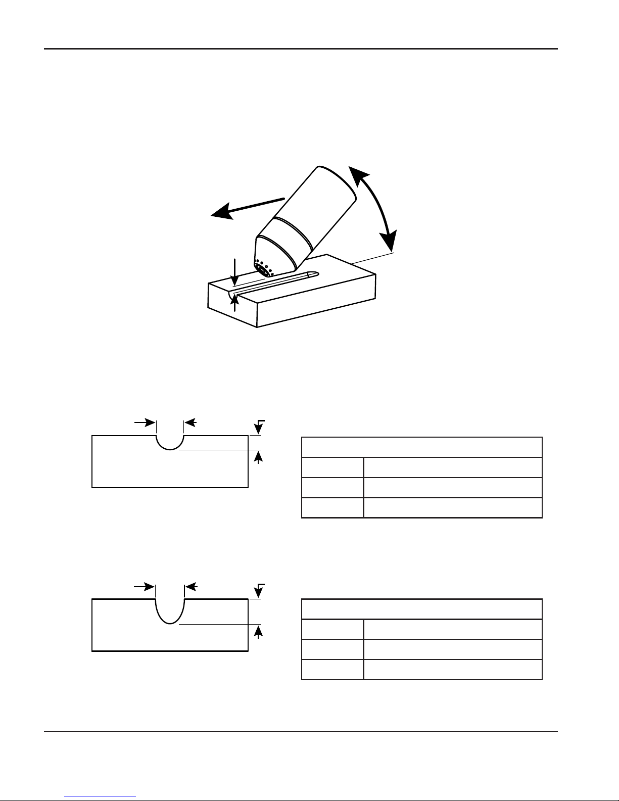
OPERATION
3-46 Duramax Retrofit Torch Operator Manual
Gouge profile
You can vary the gouge profile by varying the speed of the torch over the workpiece, varying the
torch-to-work standoff distance, varying the angle of the torch to the workpiece, and varying the
current output of the power supply.
Angle
Speed
Standoff
Typical Gouge Profile for 60A / 65A Operation
Typical Gouge Profile for 80A / 85A Operation
Width
0.26 in (6.6 mm)
Width
0.28 in (7.1 mm)
Depth
0.14 in (3.6 mm)
Depth
0.24 in (6.1 mm)
Operating parameters
Speed
20-25 ipm (50.8-63.5 cm/min)
Standoff
1/4-3/8 in (6.4-9.5 mm)
Angle
35-40°
Operating parameters
Speed
20-25 ipm (50.8-63.5 cm/min)
Standoff
1/4-3/8 in (6.4-9.5 mm)
Angle
35-40°
Page 81

OPERATION
Duramax Retrofit Torch Operator Manual 3-47
Varying the gouge profile
The following actions have the stated effects on the gouge profile:
• Increasing the speed of the torch will decrease width and decrease depth.
• Decreasing the speed of the torch will increase width and increase depth.
• Increasing the standoff of the torch will increase width and decrease depth.
• Decreasing the standoff of the torch will decrease width and increase depth.
• Increasing the angle of the torch (more vertical) will decrease width and increase
depth.
• Decreasing the angle of the torch (less vertical) will increase width and decrease
depth.
• Increasing the current of the power supply will increase width and increase depth.
• Decreasing the current of the power supply will decrease width and decrease
depth.
Typical Gouge Profile for 100 A Operation
Operating parameters
Speed
20-25 ipm (50.8-63.5 cm/min)
Standoff
1/4-3/8 in (6.4-9.5 mm)
Angle
35-40°
Depth
0.25 in (6.4 mm)
Width
0.29 in (7.4 mm)
Page 82

OPERATION
3-48 Duramax Retrofit Torch Operator Manual
Common hand-cutting faults
The torch does not cut completely through the workpiece. The causes can be:
• The cut speed is too fast.
• The consumables are worn.
• The metal being cut is too thick for the selected amperage.
• Gouging consumables are installed instead of drag-cutting consumables.
• The work clamp is not attached properly to the workpiece.
• The gas pressure or gas flow rate is too low.
Cut quality is poor. The causes can be:
• The metal being cut is too thick for the amperage.
• The wrong consumables are being used (gouging consumables are installed instead of
drag-cutting consumables, for example).
• You are moving the torch too quickly or too slowly.
The arc sputters and consumables life is shorter than expected. The cause can be:
• Moisture in the gas supply.
• Incorrect gas pressure.
• Consumables incorrectly installed.
Page 83

OPERATION
Duramax Retrofit Torch Operator Manual 3-49
Using the machine torch
Since the Powermax with a machine torch can be used with a wide variety of cutting tables, track
burners, pipe bevelers, and so on, you will need to refer to the manufacturer’s instructions for
specifics on operating the machine torch in your configuration. However, the information in the
following sections will help you optimize cut quality and maximize consumable life.
Ensure the torch and table are set up correctly
• Use a square to align the torch at right angles to the workpiece in two dimensions.
• The torch may travel more smoothly if you clean, check and “tune” the cutting table’s rails
and drive system. Unsteady machine motion can cause a regular, wavy pattern on the cut
surface.
• Ensure that the torch does not touch the workpiece during cutting. Contact with the
workpiece can damage the shield and nozzle and affect the cut surface.
Understand and optimize cut quality
There are several factors to consider in cut quality:
• Cut angle — The degree of angularity of the cut edge.
• Dross — The molten material that solidifies on the top or bottom of the workpiece.
• Straightness of the cut surface — The cut surface can be concave or convex.
The following sections explain how these factors can affect cut quality.
Cut or bevel angle
• A positive cut angle, or bevel, results when more material is removed from the top of the
cut than from the bottom.
• A negative cut angle results when more material is removed from the bottom of the cut.
Page 84

OPERATION
3-50 Duramax Retrofit Torch Operator Manual
Cause
The torch is too high.
Solution
Lower the torch; or if you are using
a torch height control, decrease the
arc voltage.
Negative cut angle
Problem
Note: The squarest cut angle will be on the right side with respect to the forward motion of
the torch. The left side will always have some degree of bevel.
To determine whether a cut-angle problem is being caused by the plasma system or the drive
system, make a test cut and measure the angle of each side. Next, rotate the torch 90° in its holder
and repeat the process. If the angles are the same in both tests, the problem is in the drive system.
If a cut-angle problem persists after “mechanical causes” have been eliminated (see “Ensure the
torch and table are set up correctly” on page 3-49), check the torch-to-work distance, especially
if the cut angles are all positive or all negative. Also consider the material being cut: if the metal is
magnetized or hardened, you are more likely to experience cut angle problems.
Dross
Some amount of dross will always be present when cutting with air plasma. However, you can
minimize the amount and type of dross by adjusting your system correctly for your application.
Excess dross appears on the top edge of both pieces of the plate when the torch is too low (or
voltage is too low when using a torch height control). Adjust the torch or adjust the voltage in small
increments (5 volts or less) until the dross is reduced.
Low-speed dross forms when the torch’s cutting speed is too slow and the arc angles ahead. It
forms as a heavy, bubbly deposit at the bottom of the cut and can be removed easily. Increase the
speed to reduce this type of dross.
The torch is too low.
Raise the torch; or if you are using
a torch height control, increase the
arc voltage.
Square cut
Positive cut angle
Page 85

OPERATION
Duramax Retrofit Torch Operator Manual 3-51
High-speed dross forms when the cutting speed is too fast and the arc angles behind. It forms
as a thin, linear bead of solid metal attached very close to the cut. It is more firmly attached to the
bottom of the cut than at low speed and is difficult to remove. To reduce high-speed dross:
• Decrease the cutting speed.
• Decrease the torch-to-work distance.
Note: Dross is more likely to form on warm or hot metal than on cool metal. For example,
the first cut in a series of cuts usually produces the least dross. As the workpiece
heats up, more dross can accumulate on subsequent cuts.
Worn or damaged consumables may produce excess dross.
Straightness of the cut surface
A typical plasma cut surface is slightly concave.
The cut surface may become more concave, or convex. Correct torch height is
required to keep the cut surface acceptably close to straight. Worn consumables also
affect the straightness of the cut.
A strongly concave cut surface occurs when the torch-to-work distance is too low.
Increase the torch-to-work distance to straighten the cut surface.
A convex cut surface occurs when the torch-to-work distance is too great or the
cutting current is too high. First, try lowering the torch, then reduce the cutting
current.
Page 86

OPERATION
3-52 Duramax Retrofit Torch Operator Manual
To pierce a workpiece using the machine torch
As with the hand torch, you can start a cut with the machine torch at the edge of the workpiece or
by piercing the workpiece. Piercing will result in a shorter consumable life than with edge starts.
The pierce delay must be sufficiently long that the arc can pierce the material before the torch
moves, but not so long that the arc “wanders” while trying to find the edge of a large hole.
When piercing maximum thicknesses, the ring of dross that forms during the pierce may become
high enough to contact the torch when the torch begins to move after the pierce is complete.
Remove the dross if the torch will contact it during the cut.
Common machine-cutting faults
The torch’s pilot arc will initiate, but will not transfer. Causes can be:
• The work cable is not making good contact with the cutting table or the cutting table is not
making good contact with the workpiece.
• The torch-to-work distance is too large.
The workpiece is not totally penetrated, and there is excessive sparking on the top of the
workpiece. Causes can be:
• The consumables are worn and need to be replaced. For optimized performance in a
mechanized application, replace the nozzle and the electrode together.
• The work cable is not making good contact with the cutting table or the cutting table is not
making good contact with the workpiece.
• The current (amperage) is set too low. See “Using the cut charts” on page 3-3 for more
information.
• The cut speed is too high. See “Using the cut charts” on page 3-3 for more information.
• The metal being cut exceeds the maximum capacity for the selected amperage.
Page 87

OPERATION
Duramax Retrofit Torch Operator Manual 3-53
Dross forms on the bottom of the cut. Causes can be:
• The consumables are worn and need to be replaced. For optimized performance in a
mechanized application, replace the nozzle and the electrode together.
• The cutting speed is not correct. See “Using the cut charts” on page 3-3 for more
information.
• The current (amperage) is set too low. See “Using the cut charts” on page 3-3 for more
information.
The cut angle is not square. Causes can be:
• The torch is not square to the workpiece.
• The consumables are worn and need to be replaced. For optimized performance in a
mechanized application, replace the nozzle and the electrode together.
• The direction of the torch travel is incorrect. The high-quality cut is always on the right with
respect to the forward motion of the torch.
• The distance between the torch and the workpiece is not correct.
• The cutting speed is not correct. See “Using the cut charts” on page 3-3 for more
information.
The consumables’ life is shortened. Causes can be:
• The arc current, arc voltage, travel speed, and other variables are not set as recommended
in the cut charts.
• Firing the arc in the air (beginning or ending the cut off of the plate surface). Starting at the
edge is acceptable as long as the arc makes contact with the workpiece when started.
• Starting a pierce with an incorrect torch height. Refer to the cut charts for the specific
initial pierce height.
Page 88

OPERATION
3-54 Duramax Retrofit Torch Operator Manual
Page 89

Duramax Retrofit Torch Operator Manual 4-1
Section 4
MAINTENANCE AND PARTS
In this section:
Perform routine maintenance .......................................................................................................................... 4-2
Inspect the consumables ................................................................................................................................. 4-3
Hand torch replacement parts ........................................................................................................................ 4-4
Machine torch replacement parts .................................................................................................................. 4-6
Accessory parts.................................................................................................................................................. 4-7
Page 90

MAINTENANCE AND PARTS
4-2 Duramax Retrofit Torch Operator Manual
Perform routine maintenance
Every use:
Check indicator lights and fault icons.
Correct any fault conditions.
Inspect the power cord and
plug. Replace if damaged.
Inspect the torch lead.
Replace if damaged.
Clean the inside of the power supply
with compressed air or a vacuum.
Replace any damaged labels.
Inspect the
consumables for
proper installation
and wear.
Inspect the trigger for
damage. Inspect the
torch body for cracks and
exposed wires. Replace
any damaged parts.
Every 6 months:
Every 3 months:
Or
AC
V
DANGER
ELECTRIC SHOCK CAN KILL
Disconnect the electrical power before you perform any maintenance.
Allwork that requires removal of the power supply cover must be
performed by a qualified technician.
Page 91

MAINTENANCE AND PARTS
Duramax Retrofit Torch Operator Manual 4-3
Part Inspect Action
Shield or
deflector
The center hole for
roundness.
The gap between the
shield and the nozzle for
accumulated debris.
Replace the shield if the
hole is no longer round.
Remove the shield and
clean away any material.
Nozzle The center hole for
roundness.
Replace nozzle if the
center hole is not
round.
Electrode Replace electrode if the
surface is worn or the
pit depth is greater than
1/16 inch (1.6mm)
deep.
Swirl ring The surface inside the swirl
ring for damage or wear and
the gas holes for blockages.
Replace swirl ring if the
surface is damaged or
worn or any of the gas
holes are blocked.
Torch o-ring The surface for damage,
wear, or a lack of lubrication.
If the o-ring is dry,
lubricate it and the
threads with a thin layer
of silicone lubricant. If
the o-ring is worn or
damaged, replace it.
Max. 1/16 in (1.6 mm)
Good Worn
Inspect the consumables
Page 92

MAINTENANCE AND PARTS
4-4 Duramax Retrofit Torch Operator Manual
Hand torch replacement parts
Duramax HRT
* The torch assembly also includes a variety of Duramax consumables.
Part number Description
005252 Trigger start switch
058519 O-ring
075504 Pilot terminal screw
075714 Handle screws, #4 x 1/2 slotted TORX pan head, S/B
228717 Kit: H65/H85/HRT Torch handle replacement
228719 Kit: H65/H85/HRT Cap-sensor switch replacement
228721 Kit: H65/H85/H65s/H85s/HRT/HRTs Safety trigger with spring replacement
228784 Kit: HRT/HRTs Torch lead replacement, 25 ft (7.6 m)
228785 Kit: HRT/HRTs Torch lead replacement, 50 ft (15.2 m)
228788* Kit: HRT Hand torch assembly with 25 ft (7.6 m) lead
228789* Kit: HRT Hand torch assembly with 50 ft (15.2 m) lead
228792 Kit: HRT Torch main body replacement
The entire hand torch and lead assembly can be replaced, or individual component parts can be
replaced.
Torch handle
Torch lead
Handle
screws
Safety trigger
and spring
O-ring
Torch head
Cap-sensor
switch
Pilot terminal
screw
Trigger start
switch
Page 93
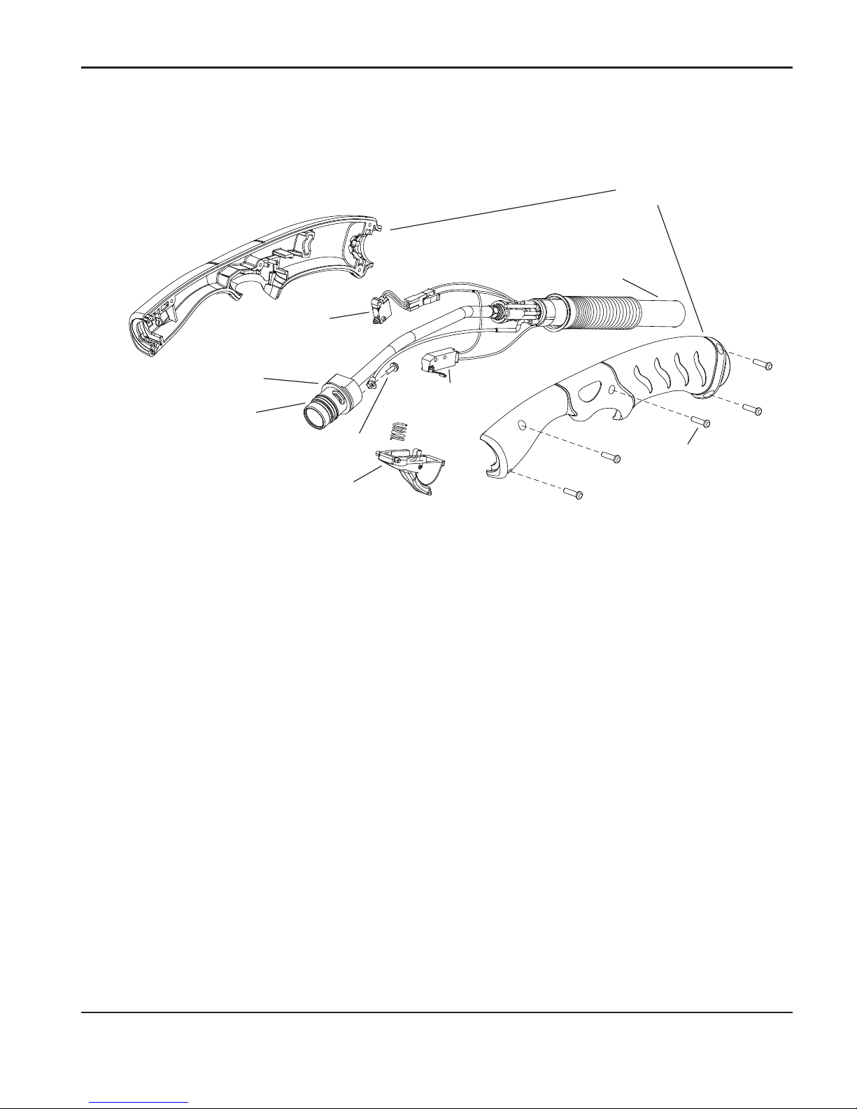
MAINTENANCE AND PARTS
Duramax Retrofit Torch Operator Manual 4-5
Duramax HRTs
* The torch assembly also includes a variety of Duramax consumables.
Part number Description
005252 Trigger start switch
058519 O-ring
075504 Pilot terminal screw
075714 Handle screws, #4 x 1/2 slotted TORX pan head, S/B
228718 Kit: H65s/H85s/HRTs Torch handle replacement
228109 Kit: H65s/H85s/HRTs Cap-sensor switch replacement
228721 Kit: H65/H85/H65s/H85s/HRT/HRTs Safety trigger with spring replacement
228784 Kit: HRT/HRTs Torch lead replacement, 25 ft (7.6 m)
228785 Kit: HRT/HRTs Torch lead replacement, 50 ft (15.2 m)
228807* Kit: HRTs Hand torch assembly with 25 ft (7.6 m) lead
228808* Kit: HRTs Hand torch assembly with 50 ft (15.2 m) lead
228809 Kit: HRTs Torch main body replacement
The entire hand torch and lead assembly can be replaced, or individual component parts can be
replaced.
Trigger start
switch
Torch handle
Torch lead
Handle
screws
Safety trigger and spring
O-ring
Torch head
Pilot terminal screw
Cap-sensor
switch
Page 94

MAINTENANCE AND PARTS
4-6 Duramax Retrofit Torch Operator Manual
Machine torch replacement parts
Duramax MRT
Front mounting ring
Pilot wire
terminal screw
Cap-sensor switch
Torch head
O-ring
Consumables
Mounting
sleeve
Coupler
Gear rack (32 pitch)
Strain relief body
Strain relief nut
Torch lead
Positioning sleeve
Wire connector for
cap-sensor switch
Page 95

MAINTENANCE AND PARTS
Duramax Retrofit Torch Operator Manual 4-7
The entire machine torch and lead assembly can be replaced, or individual component parts can
be replaced.
Part number Description
058519 O-ring
075504 Pilot terminal screw
228720 Kit: Cap-sensor switch replacement
228735 Kit: M65/M65m/M85/M85m/MRT front mounting sleeve
228736 Kit: M65/M65m/M85/M85m/MRT adapter ring (coupler)
228737 Kit: M65/M85/MRT positioning sleeve
228738 Kit: M65/M85/MRT removable gear rack
228786 Kit: MRT torch lead replacement, 25 ft (7.6 m)
228787 Kit: MRT torch lead replacement, 50 ft (15.2 m)
228790* Kit: MRT Machine torch assembly with 25 ft (7.6 m) lead
228791* Kit: MRT Machine torch assembly with 50 ft (15.2 m) lead
228793 Kit: MRT torch main body replacement
* The torch assembly also includes a variety of Duramax consumables.
Accessory parts
Part number Description
024548 Leather torch sheathing, 25 ft (7.5 m)
127102 Basic plasma (circles and lines) cutting guide
027668 Deluxe plasma (circles and lines) cutting guide
 Loading...