

Page 1

Duramax™ Retrofit Torch
HRT2 and MRT2 for
powermax600®, powermax800
®
,
powermax900
®
, MAX42®, and MAX43
®
Operator Manual – 807530
Revision 1
Page 2

Page 3

Duramax™ Retrofit Torch
HRT2 and MRT2 for
powermax600
powermax900
Operator Manual
(P/N 807530)
Revision 1 – May 2012
®
,powermax800
®
,MAX42®,and MAX43
®
,
®
Hypertherm, Inc.
Hanover, NH USA
www.hypertherm.com
email: info@hypertherm.com
© 2012 Hypertherm, Inc.
All Rights Reserved
Hypertherm, Powermax, and Duramax are trademarks of Hypertherm, Inc.
andmayberegisteredintheUnitedStatesand/ orothercountries.
Page 4

Hypertherm, Inc.
Etna Road, P.O. Box 5010
Hanover, NH 03755 USA
603-643-3441 Tel (Main Office)
603-643-5352 Fax (All Departments)
info@hypertherm.com (Main Office Email)
800-643-9878 Tel (Technical Service)
technical.service@hypertherm.com (Technical Service Email)
800-737-2978 Tel (Customer Service)
customer.service@hypertherm.com (Customer Service Email)
866-643-7711 Tel (Return Materials Authorization)
877-371-2876 Fax (Return Materials Authorization)
return.materials@hypertherm.com (RMA email)
Hypertherm Automation
5 Technology Drive, Suite 300
West Lebanon, NH 03784 USA
603-298-7970 Tel
603-298-7977 Fax
Hypertherm Plasmatechnik GmbH
Technologiepark Hanau
Rodenbacher Chaussee 6
D-63457 Hanau-Wolfgang, Deutschland
49 6181 58 2100 Tel
49 6181 58 2134 Fax
49 6181 58 2123 (Technical Service)
Hypertherm (S) Pte Ltd.
82 Genting Lane
Media Centre
Annexe Block #A01-01
Singapore 349567, Republic of Singapore
65 6841 2489 Tel
65 6841 2490 Fax
65 6841 2489 (Technical Service)
Hypertherm (Shanghai) Trading Co., Ltd.
Unit A, 5th Floor, Careri Building
432 West Huai Hai Road
Shanghai, 200052
PR China
86-21 5258 3330/1 Tel
86-21 5258 3332 Fax
Hypertherm Europe B.V.
Vaartveld 9
4704 SE
Roosendaal, Nederland
31 165 596907 Tel
31 165 596901 Fax
31 165 596908 Tel (Marketing)
31 165 596900 Tel (Technical Service)
00 800 4973 7843 Tel (Technical Service)
Hypertherm Japan Ltd.
Level 9, Edobori Center Building
2-1-1 Edobori, Nishi-ku
Osaka 550-0002 Japan
81 6 6225 1183 Tel
81 6 6225 1184 Fax
Hypertherm Brasil Ltda.
Rua Bras Cubas, 231 – Jardim Maia
Guarulhos, SP - Brasil
CEP 07115-030
55 11 2409 2636 Tel
55 11 2408 0462 Fax
Hypertherm México, S.A. de C.V.
Avenida Toluca No. 444, Anexo 1,
Colonia Olivar de los Padres
Delegación Álvaro Obregón
México, D.F. C.P. 01780
52 55 5681 8109 Tel
52 55 5683 2127 Fax
Hypertherm Korea Branch
#3904 Centum Leaders Mark B/D,
1514 Woo-dong, Haeundae-gu, Busan
Korea, 612-889
82 51 747 0358 Tel
82 51 701 0358 Fax
03/15/12
Page 5

ELECTROMAGNETIC COMPATIBILITY EMC
Introduction
Hypertherm’s CE-marked equipment is built in compliance
with standard EN60974-10. The equipment should be
installed and used in accordance with the information
below to achieve electromagnetic compatibility.
The limits required by EN60974-10 may not be adequate
to completely eliminate interference when the affected
equipment is in close proximity or has a high degree of
sensitivity. In such cases it may be necessary to use other
measures to further reduce interference.
This cutting equipment is designed for use only in an
industrial environment.
Installation and use
The user is responsible for installing and using the plasma
equipment according to the manufacturer’s instructions.
If electromagnetic disturbances are detected then it shall
be the responsibility of the user to resolve the situation
with the technical assistance of the manufacturer. In some
cases this remedial action may be as simple as earthing
the cutting circuit, see Earthing of the workpiece. In other
cases, it could involve constructing an electromagnetic
screen enclosing the power source and the work
complete with associated input filters. In all cases,
electromagnetic disturbances must be reduced to the
point where they are no longer troublesome.
Assessment of area
Before installing the equipment, the user shall make an
assessment of potential electromagnetic problems in
the surrounding area. The following shall be taken into
account:
a. Other supply cables, control cables, signaling and
telephone cables; above, below and adjacent to the
cutting equipment.
b. Radio and television transmitters and receivers.
c. Computer and other control equipment.
d. Safety critical equipment, for example guarding
ofindustrial equipment.
e. Health of the people around, for example the use
ofpacemakers and hearing aids.
f. Equipment used for calibration or measurement.
g. Immunity of other equipment in the environment. User
shall ensure that other equipment being used in the
environment is compatible. This may require additional
protection measures.
h. Time of day that cutting or other activities are to be
carried out.
The size of the surrounding area to be considered
will depend on the structure of the building and other
activities that are taking place. The surrounding area may
extend beyond the boundaries of the premises.
Methods of reducing emissions
Mains supply
Cutting equipment must be connected to the mains
supply according to the manufacturer’s recommendations.
If interference occurs, it may be necessary to take
additional precautions such as filtering of the mains
supply.
Compliance Information EMC-1
7/ 10
Page 6

ELECTROMAGNETIC COMPATIBILITY
Consideration should be given to shielding the supply
cable of permanently installed cutting equipment,
in metallic conduit or equivalent. Shielding should
be electrically continuous throughout its length. The
shielding should be connected to the cutting mains
supply so that good electrical contact is maintained
between the conduit and the cutting power source
enclosure.
Maintenance of cutting equipment
The cutting equipment must be routinely maintained
according to the manufacturer’s recommendations. All
access and service doors and covers should be closed
and properly fastened when the cutting equipment is in
operation. The cutting equipment should not be modified
in any way, except as set forth in and in accordance with
the manufacturer’s written instructions. For example,
the spark gaps of arc striking and stabilizing devices
should be adjusted and maintained according to the
manufacturer’s recommendations.
Cutting cables
The cutting cables should be kept as short as possible
and should be positioned close together, running at or
close to the floor level.
Equipotential bonding
Bonding of all metallic components in the cutting
installation and adjacent to it should be considered.
However, metallic components bonded to the workpiece
will increase the risk that the operator could receive a
shock by touching these metallic components and the
electrode (nozzle for laser heads) at the same time.
Earthing of the workpiece
Where the workpiece is not bonded to earth for
electrical safety, nor connected to earth because of its
size and position, for example, ship’s hull or building
steel work, a connection bonding the workpiece to earth
may reduce emissions in some, but not all instances.
Care should be taken to prevent the earthing of the
workpiece increasing the risk of injury to users, or
damage to other electrical equipment. Where necessary,
the connection of the workpiece to earth should be
made by a direct connection to the workpiece, but
in some countries where direct connection is not
permitted, the bonding should be achieved by suitable
capacitances selected according to national regulations.
Note: The cutting circuit may or may not be earthed for
safety reasons. Changing the earthing arrangements
should only be authorized by a person who is competent
to assess whether the changes will in crease the risk of
injury, for example, by allowing parallel cutting current
return paths which may damage the earth circuits
of other equipment. Further guidance is provided
in IEC60974-9, Arc Welding Equip ment, Part 9:
Installation and Use.
Screening and shielding
Selective screening and shielding of other cables
and equipment in the surrounding area may alleviate
problems of interference. Screening of the entire plasma
cutting installation may be considered for special
applications.
The operator should be insulated from all such bonded
metallic components.
EMC-2 Compliance Information
7/ 10
Page 7

WARRANTY
Attention
Genuine Hypertherm parts are the factoryrecommended replacement parts for your Hypertherm
system. Any damage or injury caused by the use of other
than genuine Hypertherm parts may not be covered by
the Hypertherm warranty, and will constitute misuse of
the Hypertherm Product.
You are solely responsible for the safe use of the
Product. Hypertherm does not and cannot make any
guarantee or warranty regarding the safe use of the
product in your environment.
General
Hypertherm, Inc. warrants that its Products shall be
free from defects in materials and workmanship for the
specific periods of time set forth herein and as follows:
if Hypertherm is notified of a defect (i) with respect to
the power supply within a period of two (2) years from
the date of its delivery to you, with the exception of
Powermax brand power supplies, which shall be within
a period of three (3) years from the date of delivery to
you, and (ii) with respect to the torch and leads within
a period of one (1) year from its date of delivery to you,
and with respect to torch lifter assemblies within a
period of one (1) year from its date of delivery to you,
and with respect to laser heads within a period of one
(1) year from its date of delivery to you, and with respect
to Automation products one (1) year from its date of
delivery to you, with the exception of the EDGE Pro
and MicroEDGE Pro CNCs and ArcGlide THC, which
shall be within a period of two (2) years from the date of
delivery to you.
Hypertherm provides repair, replacement or adjustment
of the Product as the sole and exclusive remedy, if
and only if the warranty set forth herein properly is
invoked and applies. Hypertherm, at its sole option,
shall repair, replace, or adjust, free of charge, any
defective Products covered by this warranty which
shall be returned with Hypertherm’s prior authorization
(which shall not be unreasonably withheld), properly
packed, to Hypertherm’s place of business in Hanover,
New Hampshire, or to an authorized Hypertherm repair
facility, all costs, insurance and freight pre paid by the
customer. Hypertherm shall not be liable for any repairs,
replacement, or adjustments of Products covered by this
warranty, except those made pursuant to this paragraph
and with Hypertherm’s prior written consent.
The warranty set forth above is exclusive and is in
lieu of all other warranties, express, implied, statutory,
or otherwise with respect to the Products or as to
the results which may be obtained therefrom, and
all implied warranties or conditions of quality or of
merchantability or fitness for a particular purpose or
against infringement. The foregoing shall constitute the
sole and exclusive remedy for any breach by Hypertherm
of its warranty.
Distributors/OEMs may offer different or additional
warranties, but Distributors/OEMs are not authorized to
give any additional warranty protection to you or make
any representation to you purporting to be binding upon
Hypertherm.
This warranty shall not apply to any Powermax brand
power supplies that have been used with phase
converters. In addition, Hypertherm does not warranty
systems that have been damaged as a result of poor
power quality, whether from phase converters or
incoming line power. This warranty shall not apply to any
Product which has been incorrectly installed, modified,
or otherwise damaged.
Compliance Information W-1
9/10
Page 8

WARRANTY
Patent indemnity
Except only in cases of products not manufactured by
Hypertherm or manufactured by a person other than
Hypertherm not in strict conformity with Hypertherm’s
specifications and in cases of designs, processes,
formulae, or combinations not developed or purported
to be developed by Hypertherm, Hypertherm will have
the right to defend or settle, at its own expense, any
suit or proceeding brought against you alleging that
the use of the Hypertherm product, alone and not in
combination with any other product not supplied by
Hypertherm, infringes any patent of any third party. You
shall notify Hypertherm promptly upon learning of any
action or threatened action in connection with any such
alleged infringement (and in any event no longer than
fourteen (14) days after learning of any action or threat
of action), and Hypertherm’s obligation to defend shall
be conditioned upon Hypertherm’s sole control of, and
the indemnified party’s cooperation and assistance in,
the defense of the claim.
Limitation of liability
In no event shall Hypertherm be liable to any
person or entity for any incidental, consequential
direct, indirect, punitive or exemplary damages
(including but not limited to lost profits)
regardless of whether such liability is based on
breach of contract, tort, strict liability, breach
of warranty, failure of essential purpose, or
otherwise, and even if advised of the possibility
of such damages.
Insurance
At all times you will have and maintain insurance in such
quantities and types, and with coverage sufficient and
appropriate to defend and to hold Hypertherm harmless
in the event of any cause of action arising from the use
of the products.
Transfer of rights
You may transfer any remaining rights you may have
hereunder only in connection with the sale of all or
substantially all of your assets or capital stock to a
successor in interest who agrees to be bound by all of
the terms and conditions of this Warranty. Within thirty
(30) days before any such transfer occurs, you agree to
notify in writing Hypertherm, which reserves the right of
approval. Should you fail timely to notify Hypertherm and
seek its approval as set forth herein, the Warranty set
forth herein shall be null and void and you will have no
further recourse against Hypertherm under the Warranty
or otherwise.
National and local codes
National and local codes governing plumbing and
electrical installation shall take precedence over any
instructions contained in this manual. In no event shall
Hypertherm be liable for injury to persons or property
damage by reason of any code violation or poor work
practices.
Liability cap
In no event shall Hypertherm’s liability, if any,
whether such liability is based on breach of
contract, tort, strict liability, breach of warranties,
failure of essential purpose or otherwise, for
any claim, action, suit or proceeding (whether
in court, arbitration, regulatory proceeding or
otherwise) arising out of or relating to the use of
the Products exceed in the aggregate the amount
paid for the Products that gave rise to such claim.
W-2 Compliance Information
9/10
Page 9

Safety information
Before operating any Hypertherm equipment, read the separate Safety and Compliance Manual (80669C) included
with your product for important safety information.
Page 10

Page 11

Table of ConTenTs
ELECTROMAGNETIC COMPATIBILITY (EMC) ....................................................................................................... EMC-1
WARRANTY ........................................................................................................................................................................... W-1
Safety information ..................................................................................................................................................................... 2
Section 1
Specifications ......................................................................................................................................................................... 1-1
Component weights .................................................................................................................................................................................1-2
Duramax HRT2 hand torch dimensions ...............................................................................................................................................1-2
Duramax MRT2 full-length machine torch dimensions .....................................................................................................................1-2
Duramax MRT2 without positioning sleeve (mini torch) ...................................................................................................................1-2
Section 2
Torch Setup ............................................................................................................................................................................. 2-1
Introduction ................................................................................................................................................................................................2-2
Consumable life .........................................................................................................................................................................................2-2
Hand torch setup ......................................................................................................................................................................................2-2
Choose the hand torch consumables .......................................................................................................................................2-3
Install the hand torch consumables ............................................................................................................................................2-4
Machine torch setup.................................................................................................................................................................................2-5
Converting a Duramax retrofit machine torch into a mini torch ...........................................................................................2-6
Mount the torch ...............................................................................................................................................................................2-8
Choose the machine torch consumables .............................................................................................................................. 2-10
Install the machine torch consumables .................................................................................................................................. 2-12
Aligning the torch ........................................................................................................................................................................ 2-12
Torch installation .................................................................................................................................................................................... 2-13
Torches with a quick disconnect connector ......................................................................................................................... 2-13
Torches without a quick disconnect connector - Powermax600 CE ............................................................................. 2-14
ON/OFF Pendant connection .................................................................................................................................................. 2-15
Section 3
Operation ................................................................................................................................................................................. 3-1
Using the cut charts .................................................................................................................................................................................3-2
55 amp mechanized shielded consumables ............................................................................................................................3-3
50 amp mechanized shielded consumables ............................................................................................................................3-4
45 amp mechanized shielded consumables ............................................................................................................................3-5
40 amp mechanized shielded consumables ............................................................................................................................3-8
45 amp mechanized unshielded consumables .......................................................................................................................3-9
40 amp mechanized unshielded consumables .................................................................................................................... 3-12
FineCut® consumables .............................................................................................................................................................. 3-13
Using the hand torch ............................................................................................................................................................................. 3-17
Operate the safety trigger ......................................................................................................................................................... 3-17
Hand torch cutting hints ............................................................................................................................................................ 3-18
Start a cut from the edge of the workpiece...........................................................................................................................3-19
Pierce a workpiece ...................................................................................................................................................................... 3-20
Gouge a workpiece .................................................................................................................................................................... 3-21
General guidelines for gouging ................................................................................................................................................ 3-22
Duramax Retrofit Torch Operator Manual i
Page 12

Table of ConTenTs
Common hand-cutting faults .................................................................................................................................................... 3-22
Using the machine torch ...................................................................................................................................................................... 3-23
Ensure the torch and table are set up correctly ................................................................................................................... 3-23
Understand and optimize cut quality ....................................................................................................................................... 3-23
To pierce a workpiece using the machine torch .................................................................................................................. 3-26
Common machine-cutting faults .............................................................................................................................................. 3-26
Section 4
Maintenance and parts ........................................................................................................................................................ 4-1
Perform routine maintenance .................................................................................................................................................................4-2
Inspect the consumables ........................................................................................................................................................................4-3
Hand torch replacement parts – Duramax HRT
Machine torch replacement parts – Duramax MRT
Accessory parts.........................................................................................................................................................................................4-6
2 ...........................................................................................................................................................................4-4
2 ...................................................................................................................................................................4-5
ii Duramax Retrofit Torch Operator Manual
Page 13

Section 1
Specifications
In this section:
Component weights ......................................................................................................................................................................................... 1-2
Duramax HRT2 hand torch dimensions .......................................................................................................................................................1-2
Duramax MRT2 full-length machine torch dimensions ............................................................................................................................. 1-2
Duramax MRT2 without positioning sleeve (mini torch) ........................................................................................................................... 1-2
Duramax Retrofit Torch Operator Manual 1-1
Page 14
SpecificationS
Component weights
Torch type Weight – kg (lbs)
Hand torch 7.6 m (25 ft) 3.2 (7.1)
Hand torch 15 m (50 ft) 5.7 (12.6)
Machine torch 7.6 m (25 ft) 3.4 (7.5)
Machine torch 15 m (50 ft) 5.9 (13.0)
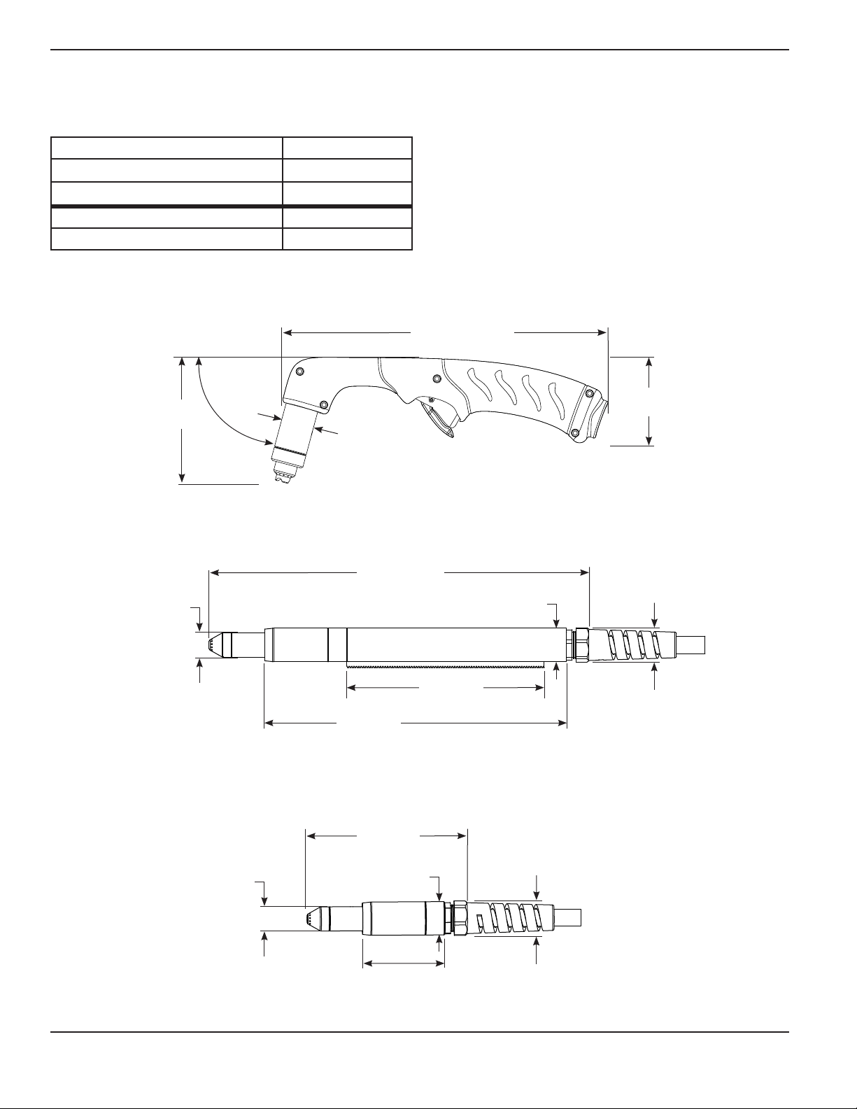
Duramax HRT2 hand torch dimensions
25.2 cm (9.9 in.)
75°
9.8 cm
(3.8 in.)
angle
2.5 cm
(1.0 in.)
Duramax MRT2 full-length machine torch dimensions
39.6 cm
(15.6 in.)
2.5 cm
(1.0 in.)
20.6 cm
(8.1 in.)
31.3 cm
(12.3 in.)
3.5 cm
(1.4 in.)
Duramax MRT2 without positioning sleeve (mini torch)
6.6 cm
(2.6 in.)
3.6 cm (1.4 in.) outer
dimension, 3.3 cm
(1.3 in.) flat sides
16.8 cm
(6.6 in.)
2.5 cm
(1.0 in.)
3.5 cm
(1.4 in.)
8.4 cm
(3.3 in.)
3.6 cm (1.4 in.) outer
dimension, 3.3 cm
(1.3 in.) flat sides
1-2 Duramax Retrofit Torch Operator Manual
Page 15

Section 2
Torch Setup
In this section:
Introduction ........................................................................................................................................................................................................ 2-2
Consumable life ................................................................................................................................................................................................. 2-2
Hand torch setup .............................................................................................................................................................................................. 2-2
Choose the hand torch consumables ............................................................................................................................................... 2-3
Install the hand torch consumables .................................................................................................................................................... 2-4
Machine torch setup......................................................................................................................................................................................... 2-5
Converting a Duramax retrofit machine torch into a mini torch ................................................................................................... 2-6
Mount the torch ....................................................................................................................................................................................... 2-8
Choose the machine torch consumables ....................................................................................................................................... 2-10
Install the machine torch consumables ...........................................................................................................................................2-12
Aligning the torch .................................................................................................................................................................................2-12
Torch installation .............................................................................................................................................................................................2-13
Torches with a quick disconnect connector ..................................................................................................................................2-13
Torches without a quick disconnect connector - Powermax600 CE ......................................................................................2-14
ON/OFF Pendant connection ...........................................................................................................................................................2-15
Duramax Retrofit Torch Operator Manual 2-1
Page 16
Torch seTup
Introduction
Duramax™ series handheld and machine retrofit torches are available for the Powermax600, Powermax800, Powermax900,
MAX42, and MAX43 systems. The torches are cooled by ambient air and do not require special cooling procedures.
This section explains how to setup your torch and choose the appropriate consumables for the job.
Consumable life
How often you need to change the consumables on your retrofit torch will depend on a number of factors:
• Thickness of the material – the thicker the material being cut, the more often consumables need to be changed.
• Average length of cut – the longer the average cut, the more often consumables need to be changed.
• Type of cutting – handheld cutting will require more consumable changes than machine cutting.
• Air quality – the presence of oil, moisture, or other contaminants will reduce consumable life.
• Piercing / edge starting – piercing the metal causes more consumable wear then starting cuts from the edge of the
metal.
• Proper torch-to-work distance – when gouging or cutting with unshielded consumables, maintaining proper torchto-work distance will result in better consumable life.
• Proper pierce height – maintaining proper pierce height will result in better consumable life.
• Cutting in “continuous pilot arc” mode or normal cutting mode – cutting with a continuous pilot arc causes more
consumable wear than cutting in normal cutting mode.
You will find more information about proper cutting techniques in Section 3, Operation.
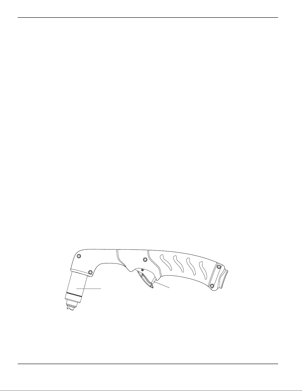
Hand torch setup
Duramax HRT
2
Consumables
Safety trigger
2-2 Duramax Retrofit Torch Operator Manual
Page 17
TORCH SETUP
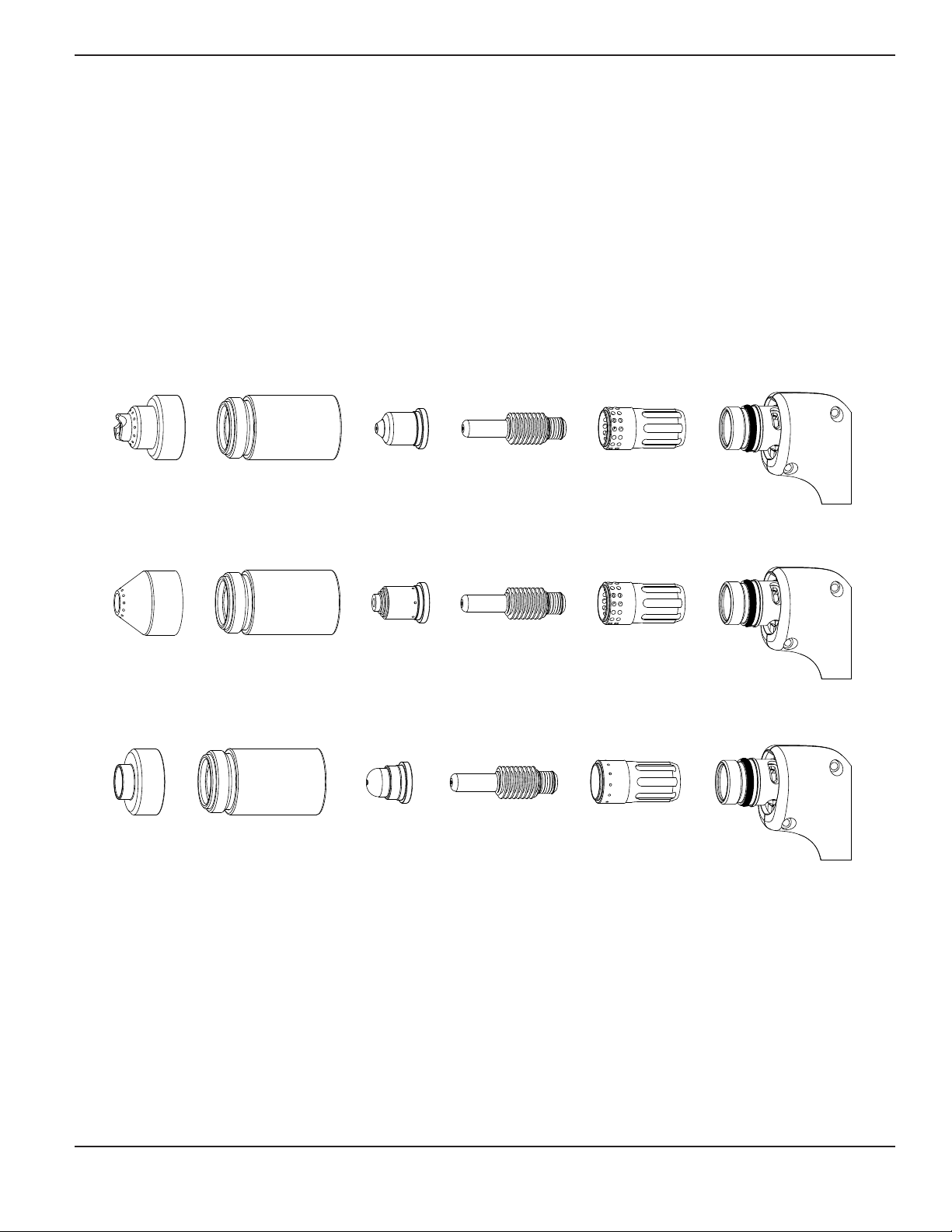
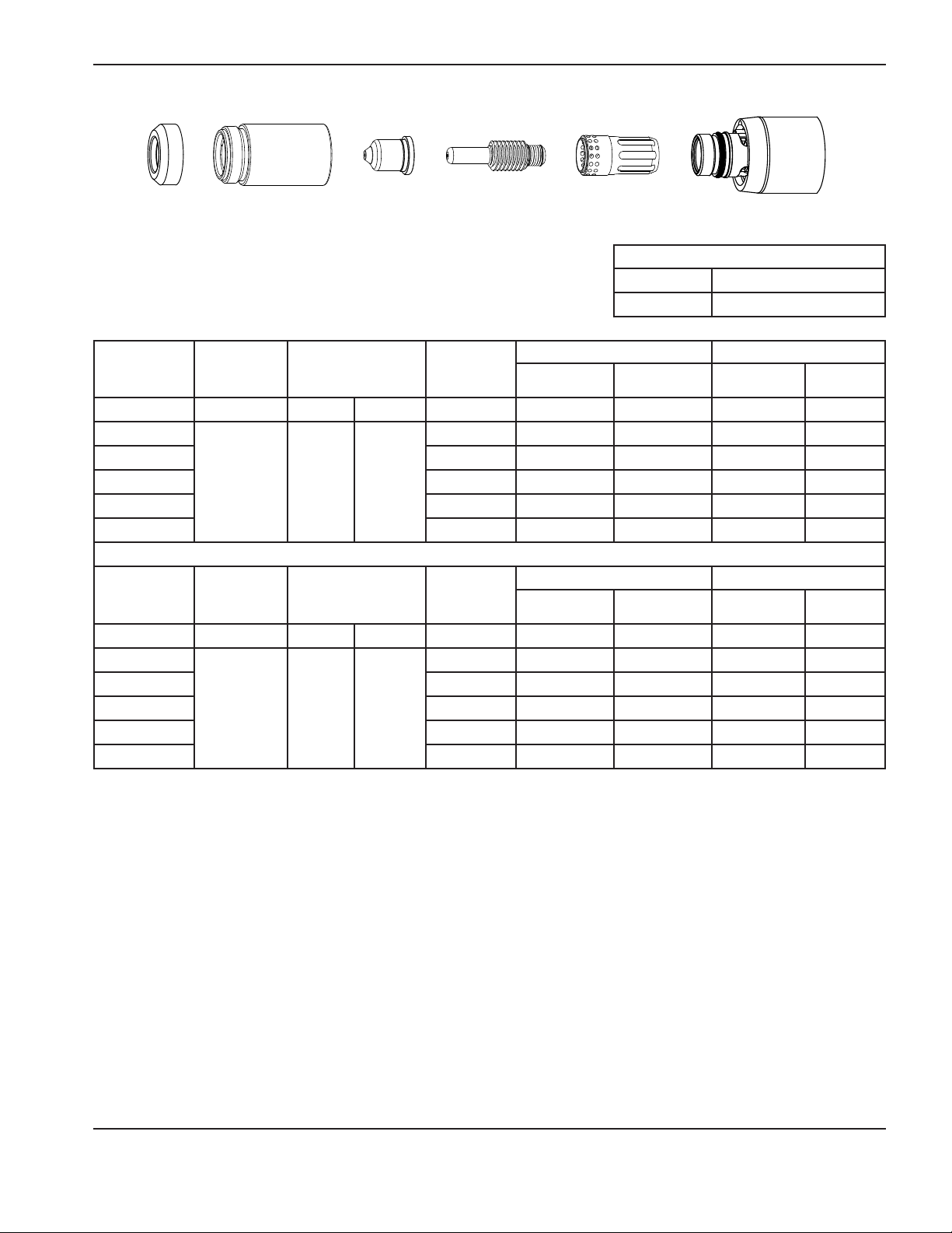
Choose the hand torch consumables
Duramax retrofit torches are shipped with a full set of cutting consumables pre-installed. Hypertherm also includes spare
cutting electrodes, nozzles, and gouging consumables in the consumables box, for handheld torches.
Consumables for handheld cutting are shown on the next page. Notice that the retaining cap and electrode are the same for
cutting, gouging, and FineCut® applications. Only the shield, nozzle, and swirl ring are different.
For the best cut quality on thin materials, you may prefer to use FineCut consumables, or use a 45A nozzle and reduce the
current setting to 45 or 40 amps.
Hand torch consumables
Drag-cutting consumables
4
5
A
220818
Shield
Gouging consumables
220798
Shield
FineCut® consumables
220931
Shield
Retaining cap
220854
Retaining cap
220854
Retaining cap
220854
220941
Nozzle
220797
Nozzle
220930
Nozzle
220842
Electrode
220842
Electrode
220842
Electrode
220857
Swirl ring
220857
Swirl ring
220947
Swirl ring
Duramax Retrofit Torch Operator Manual 2-3
Page 18
Torch seTup
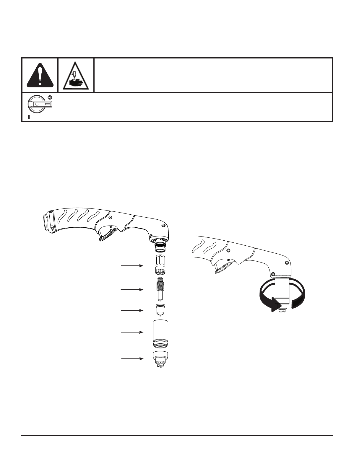
Install the hand torch consumables
WARNING
INSTANTON TORCHES
PLASMA ARC CAN CAUSE INJURY AND BURNS
The plasma arc comes on im me di ate ly when the torch trigger is activated. Make sure the
power is OFF before changing consumables.
To operate the hand torch, a complete set of consumable parts must be installed: shield, retaining cap, nozzle, electrode,
and swirl ring.
With the power switch in the OFF (O) position, install the torch consumables asshown below.
Swirl ring
Electrode
Nozzle
Retaining cap
Shield
2-4 Duramax Retrofit Torch Operator Manual
Page 19

Machine torch setup
TORCH SETUP
Duramax MRT
2
Consumables
Mounting
sleeve
Coupler
Positioning sleeve
Gear rack
Duramax MRT2 without positioning sleeve (mini torch)
Consumables
Mounting
sleeve
Coupler
Strain relief
nut
Strain relief nut
Main strain
Torch lead
Strain relief
body
relief nut
Torch lead
Strain relief
body
Before using either style of machine torch, you must:
• Mount the torch on your cutting table or other equipment.
• Choose and install the consumables.
• Align the torch.
• Attach the torch lead to the power supply.
• Set up the power supply for remote starting with either the remote-start pendant or a machine interface cable.
Duramax Retrofit Torch Operator Manual 2-5
Page 20
Torch seTup
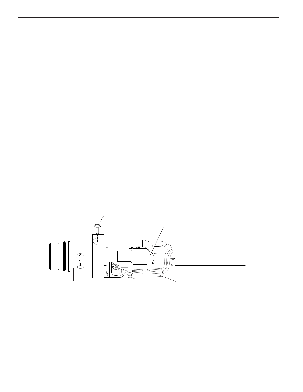
Converting a Duramax retrofit machine torch into a mini torch
You can convert a full-length machine torch to a mini-machine torch by removing the positioning sleeve. Refer to the figures
on the previous page while completing the following instructions.
Note: If you are converting a full-length machine torch to a mini-machine torch and mounting the torch at the same
time, skip this section and follow the instructions in the next section, “Mount the torch”.
1. Disconnect the torch lead from the power supply and remove the consumables from the torch.
Note: While disconnecting and reconnecting the torch parts, maintain the same orientation between the torch body
and torch lead. Twisting the torch body in relation to the torch lead can cause damage.
2. Unscrew the strain relief body from the strain relief nut and slide the strain relief body back along the torch lead.
3. Unscrew the strain relief nut from the positioning sleeve and slide the nut back along the torch lead.
4. Unscrew the positioning sleeve from the coupler.
5. Unscrew the coupler from the mounting sleeve.
6. Remove the three screws from the consumables end of the mounting sleeve and slide the mounting sleeve off the front
of the torch body.
7. Disconnect the wire connector for the cap-sensor switch.
8. Use a #2 Phillips screwdriver to remove the screw that secures the pilot arc wire to the torch body.
9. Use 1/4-inch and 3/8-inch wrenches, or two adjustable wrenches, to loosen the nut that secures the gas supply line to
the torch body. Set the torch body aside.
10. Slide the coupler and positioning sleeve off the front of the torch lead.
Pilot arc wire
terminal screw
Gas supply line nut
Torch body
Wire connector for
cap-sensor switch
2-6 Duramax Retrofit Torch Operator Manual
Page 21

TORCH SETUP
11. Slide the coupler over the torch lead.
12. Use two wrenches to tighten the gas supply line nut onto the threaded torch body fitting.
13. Secure the pilot arc wire to the torch body by tightening the pilot arc wire terminal screw.
14. Reconnect the cap-sensor switch’s wire connector.
15. Slide the mounting sleeve over the front of the torch body. Align the slot on the front of the mounting sleeve (next to one
of the three screw holes) with the cap-sensor plunger on the torch body.
16. Secure the mounting sleeve to the torch body by tightening the three screws.
17. Screw the coupler into the mounting sleeve.
18. Screw the strain relief nut into the coupler.
19. Screw the strain relief body into the strain relief nut.
Duramax Retrofit Torch Operator Manual 2-7
Page 22

Torch seTup
Mount the torch
Depending on the type of cutting table you have, you may or may not need to disassemble the torch to route it through the
track and mount it. If your cutting table’s track is large enough for you to thread the torch through it without removing the
torch body from the lead, do so and then attach the torch to the lifter per the manufacturer’s instructions.
Note: The Duramax machine torches can be mounted on a wide variety of X-Y tables, track burners, pipe bevelers,
and other equipment. Install the torch per the manufacturer’s instructions and follow the instructions below for
disassembly if necessary.
If you need to disassemble and reassemble the torch, refer to the figures in the “Machine torch setup” section while
completing the following instructions.
1. Disconnect the torch lead from the power supply and remove the consumables from the torch.
Note: While disconnecting and reconnecting the torch parts, maintain the same orientation between the torch body
and torch lead. Twisting the torch body in relation to the torch lead can cause damage.
2. Unscrew the strain relief body from the strain relief nut and slide the strain relief body back along the torch lead.
3. Unscrew the strain relief nut from the positioning sleeve (full-length machine torch) and slide the nut back along the
torch lead.
4. Unscrew the positioning sleeve from the coupler.
5. Unscrew the coupler from the mounting sleeve.
6. Remove the three screws from the consumables end of the mounting sleeve and slide the mounting sleeve off the front
of the torch body.
7. Disconnect the wire connector for the cap-sensor switch.
8. Use a #2 Phillips screwdriver to remove the screw that secures the pilot arc wire to the torch body.
Pilot arc wire
terminal screw
Gas supply line nut
Torch body
Wire connector for
cap-sensor switch
2-8 Duramax Retrofit Torch Operator Manual
Page 23

TORCH SETUP
9. Use 1/4-inch and 3/8-inch wrenches, or two adjustable wrenches, to loosen the nut that secures the gas supply line to
the torch body. Set the torch body aside.
Note: Cover the end of the gas line on the torch lead with tape to keep dirt and other contaminants from getting in
the gas line when you route the lead through the track.
10. Slide the coupler, positioning sleeve (full-length machine torch), strain relief nut, and strain relief body off the front of the
torch lead.
11. If you do not need the gear rack on a full-length machine torch, slide the gear rack from the positioning sleeve toward
the consumables end of the sleeve.
12. Route the torch lead through the cutting table’s track.
13. Slide the strain relief body and strain relief nut over the torch lead.
14. If you are mounting a full-length machine torch, slide the positioning sleeve over the torch head.
15. Slide the coupler over the torch lead.
16. Use two wrenches to tighten the gas supply line nut onto the threaded torch body fitting.
17. Secure the pilot arc wire to the torch body by tightening the pilot arc wire terminal screw.
18. Reconnect the cap-sensor switch’s wire connector.
19. Slide the mounting sleeve over the front of the torch body. Align the slot on the front of the mounting sleeve (next to one
of the three screw holes) with the cap-sensor plunger on the torch body.
20. Secure the mounting sleeve to the torch body by tightening the three screws.
21. Screw the coupler into the mounting sleeve.
22. If you are mounting a full-length machine torch, screw the positioning sleeve into the coupler.
23. Reconnect the strain relief nut and strain relief body.
24. Attach the torch to the lifter per the manufacturer’s instructions.
Duramax Retrofit Torch Operator Manual 2-9
Page 24

Torch seTup
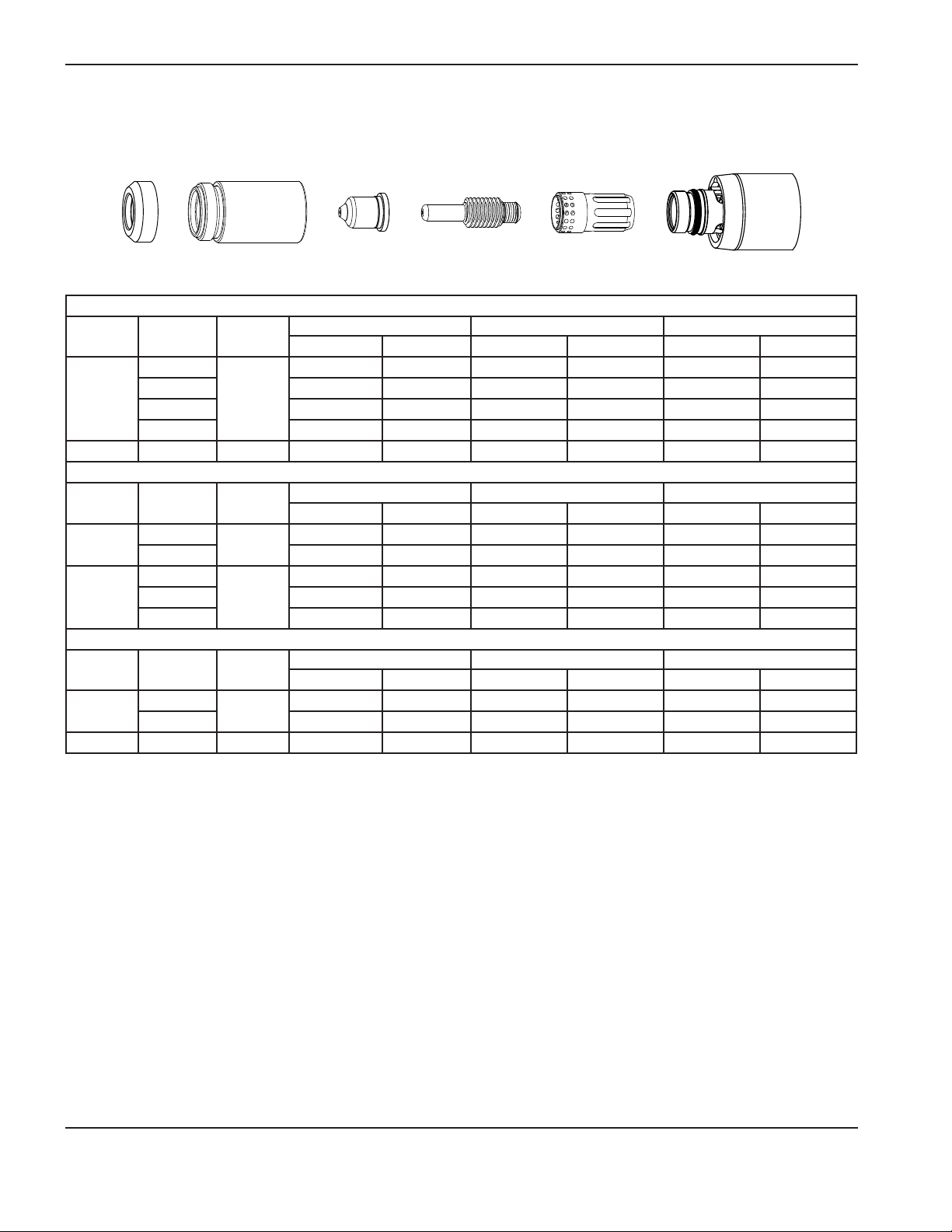
Choose the machine torch consumables
Powermax systems with the Duramax MRT2 retrofit torch are shipped with a complete set of consumables. Hypertherm
also includes spare electrodes and nozzles. In addition, an ohmic-sensing retaining cap is available for use with shielded
consumables. With shielded consumables, the torch tip may touch the metal when cutting. With unshielded consumables,
you must keep the torch a small distance, about 2 mm (0.08 inch), away from the metal. Unshielded consumables generally
have a shorter life than shielded consumables.
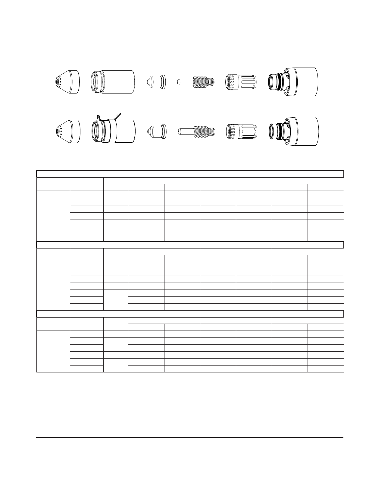
Machine torch consumables
Mechanized shielded consumables
4
5
A
220817
Shield
220854
Retaining cap
220941
Nozzle
Mechanized shielded with ohmic consumables
4
5
A
220817
Shield
220953
Ohmic-sensing
retaining cap
220941
Nozzle
Mechanized unshielded consumables
4
5
A
220955
Deflector
220854
Retaining cap
220941
Nozzle
220842
Electrode
220842
Electrode
220842
Electrode
220857
Swirl ring
220857
Swirl ring
220857
Swirl ring
2-10 Duramax Retrofit Torch Operator Manual
Page 25

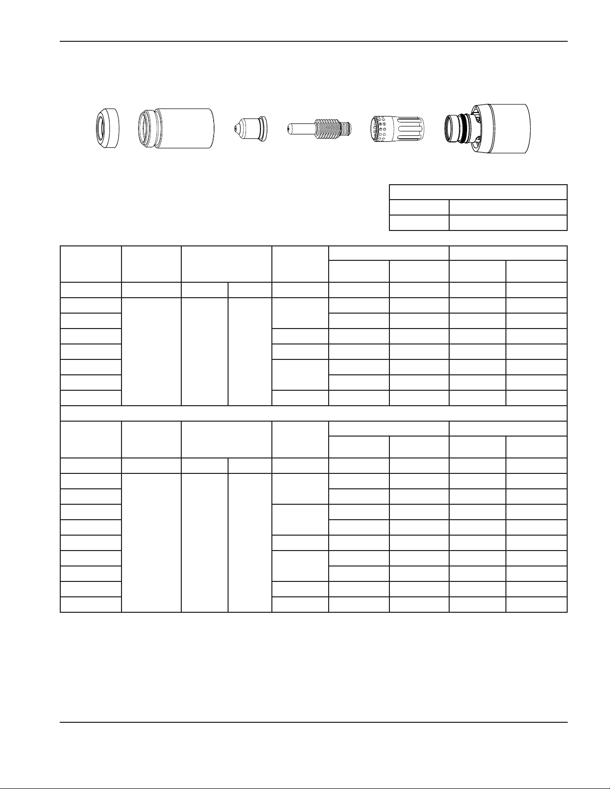
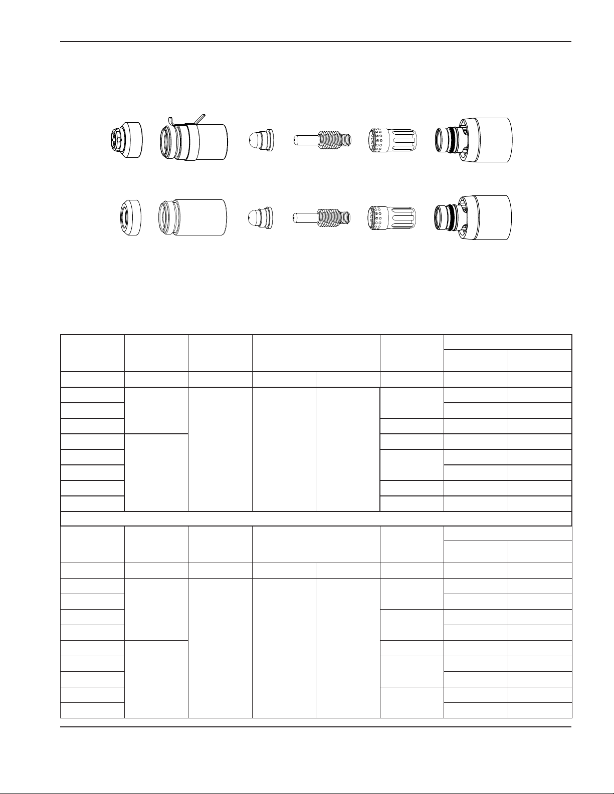
Gouging consumables
TORCH SETUP
FineCut
FineCut
220798
Shield
®
shielded
220948
Shield
®
unshielded consumables
220955
Deflector
220854
Retaining cap
220953
Retaining cap
220854
Retaining cap
220797
Nozzle
220930
Nozzle
220930
Nozzle
220842
Electrode
220842
Electrode
220842
Electrode
220857
Swirl ring
220857
Swirl ring
220857
Swirl ring
Duramax Retrofit Torch Operator Manual 2-11
Page 26

Torch seTup
Install the machine torch consumables
WARNING
INSTANT-ON TORCHES
PLASMA ARC CAN CAUSE INJURY AND BURNS
The plasma arc comes on im me di ate ly when the torch is activated. Make sure the power
is OFF before changing the consumables.
To operate the machine torch, a complete set of consumable parts must be installed: shield, retaining cap, nozzle, electrode,
and swirl ring.
With the power switch in the OFF (O) position, install the machine torch consumables in a manner similar to the hand torch
consumables. Refer to “Install the hand torch consumables” on page 2-4.
Aligning the torch
Mount the machine torch perpendicular to the workpiece in order to get a vertical cut. Use a square to align the torch at 0°
and 90°.
Torch
0°
90°
2-12 Duramax Retrofit Torch Operator Manual
Page 27
TORCH SETUP
Torch installation
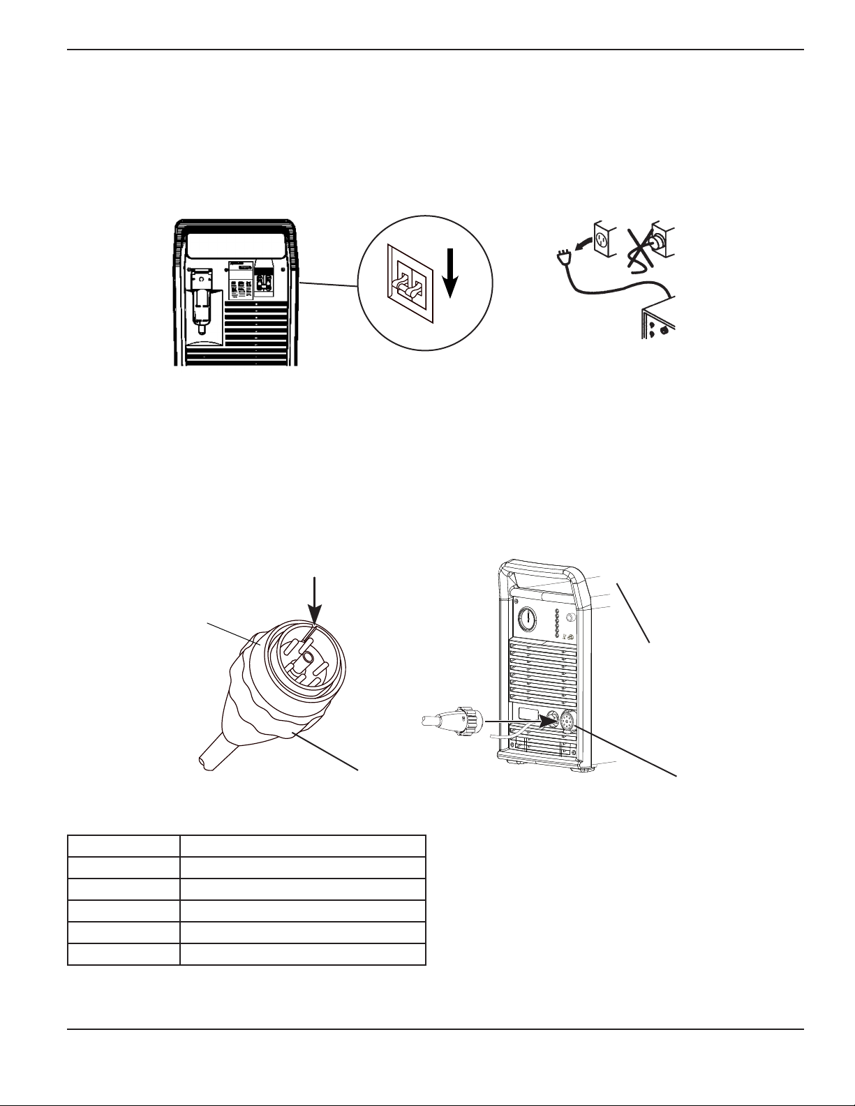
Torches with a quick disconnect connector
1. Turn OFF the power switch and remove the power cord from the power receptacle.
2. Disconnect the gas supply hose from the power supply.
3. Align the connector key-way on the torch lead with the receptacle on the power supply and push in until the pins seat.
4. Before tightening, turn the connector securing ring 1/4 turn to the left to ensure that the securing ring threads and the
connector receptacle threads are aligned.
5. Turn the securing ring to the right to tighten.
6. Clean the top of the power supply and apply the new consumable label over the existing label.
Key-way
Quick disconnect
connector
Consumable label
(Part # 210126)
Securing ring
Note: If the receptacle is missing or damaged it should be replaced with a new receptacle.
Part Number Description
028522 MAX42 receptacle
028523 MAX43 receptacle
029962 Powermax800 receptacle
128493 Powermax600 receptacle
129325 Powermax900 receptacle
Receptacle
Duramax Retrofit Torch Operator Manual 2-13
Page 28

Torch seTup
3
5
6
2
7
3
5
6
4
Torches without a quick disconnect connector - Powermax600 CE
1. Turn OFF the power switch and remove the power cord from the power receptacle.
2. Disconnect the gas supply hose from the power supply.
Caution: Do not tighten the strain relief collar (4) onto the torch lead until the gas fitting (3) is tight, or the gas
connection may leak.
3. Install the strain relief (1) and secure with nut (2).
4. Connect and tighten the gas fitting (3).
5. Tighten the strain relief collar (4) onto the lead.
6. Connect the electrical connections (5), (6) and (7). Tighten
the terminal block screws to 12 kg cm (10 in.-lb).
Caution: These are high current connections. Proper
torque is critical.
1
7
2-14 Duramax Retrofit Torch Operator Manual
Page 29

ON/OFF Pendant connection
TORCH SETUP
On/Off pendant
The Duramax MRT2 torch lead is supplied with a pigtail so that the on/off pendant may be used. If you want to use a different
on/off switch configuration, note that the wiring configuration to the 3-socket female receptacle on the pigtail is as follows:
Socket A White Wire
Socket B Not Used
Socket C Black Wire
Pigtail from machine
torch lead
Duramax Retrofit Torch Operator Manual 2-15
Page 30

Torch seTup
2-16 Duramax Retrofit Torch Operator Manual
Page 31

Section 3
Operation
In this section:
Using the cut charts ..................................................................................................................................................................................3-2
55 amp mechanized shielded consumables .............................................................................................................................3-3
50 amp mechanized shielded consumables .............................................................................................................................3-4
45 amp mechanized shielded consumables .............................................................................................................................3-5
40 amp mechanized shielded consumables .............................................................................................................................3-8
45 amp mechanized unshielded consumables ........................................................................................................................3-9
40 amp mechanized unshielded consumables .....................................................................................................................3-12
FineCut® consumables ............................................................................................................................................................... 3-13
Using the hand torch ..............................................................................................................................................................................3-17
Operate the safety trigger ..........................................................................................................................................................3-17
Hand torch cutting hints .............................................................................................................................................................3-18
Start a cut from the edge of the workpiece............................................................................................................................3-19
Pierce a workpiece .......................................................................................................................................................................3-20
Gouge a workpiece .....................................................................................................................................................................3-21
General guidelines for gouging ................................................................................................................................................. 3-22
Common hand-cutting faults ..................................................................................................................................................... 3-22
Using the machine torch .......................................................................................................................................................................3-23
Ensure the torch and table are set up correctly .................................................................................................................... 3-23
Understand and optimize cut quality ........................................................................................................................................3-23
To pierce a workpiece using the machine torch ................................................................................................................... 3-26
Common machine-cutting faults ............................................................................................................................................... 3-26
Duramax Retrofit Torch Operator Manual 3-1
Page 32

OPERATION
Using the cut charts
The following sections provide cut charts for each set of mechanized consumables. A consumable diagram with part
numbers precedes each cut chart.
The cut charts are intended to provide a good starting point for each different cut assignment. Every cutting system
requires “fine tuning” for each cutting application in order to obtain the desired cut quality.
The arc voltage increases as the consumables wear and the voltage setting should be increased to maintain the correct
Torch-to-Work Distance.
The 45 amp nozzle (part number 220941) provides the best results across the 40 - 55 amp cutting range for both the
mechanized shielded and unshiedled consumables.
Note: Hypertherm collected the data under laboratory test conditions using new consumables.
• Maximum travel speeds are the fastest travel speeds possible to cut the material without regard to cut quality.
• Optimum travel speeds provide the best cut angle, least dross and best cut surface finish.
• Best Quality Settings (cut speed and voltage) — Settings that provide the starting point for finding the best
cut quality (best angle, least dross, best cut-surface finish). Adjust the speed for your application and table to
obtain the desired result.
• Production Settings (cut speed and voltage) — 80% of the maximum speed ratings. These speeds result in the
greatest number of cut parts, but not necessarily the best possible cut quality.
3-2 Duramax Retrofit Torch Operator Manual
Page 33
55 amp mechanized shielded consumables
•Torch-to-workdistanceforthefollowingcutchartis1.5mm(1/16inch)forallcuts.
4
5
A
OPERATION
220817
Shield
220817
Shield
Ohmic-sensing
Mild Steel
Arc Current Arc Voltage
134
127
134 0.25
55
138 0.75
144
146
149
Stainless
Arc Current Arc Voltage
134 0
136 0.25
139 0.50
55
145 0.75
146
149
154
Aluminum
Arc Current Arc Voltage
135 0
138
55
141
146 0.75
149
153
220854
Retaining cap
220953
retaining cap
Motion
Delay
0
*
Motion
Delay
*
Motion
Delay
0.25
*
220941
Nozzle
4
5
A
220941
Nozzle
Material Thickness Maximum Travel Speeds Optimum Travel Speeds
Inches mm
16 Ga 1.5
10 Ga 3.4
1/4” 6.4
3/8” 9.5
1/2” 12.7
5/8” 15.9
3/4” 19.0
Material Thickness Maximum Travel Speeds Optimum Travel Speeds
Inches mm
16 Ga 4.8
10 Ga 3.4
1/4” 6.4
3/8” 9.5
1/2” 12.7
5/8” 15.9
3/4” 19.0
Material Thickness Maximum Travel Speeds Optimum Travel Speeds
Inches mm
1/16” 1.6
1/8” 3.2
1/4” 6.4
3/8” 9.5
1/2” 12.7
5/8” 15.9
220842
Electrode
220842
Electrode
IPM mm/min IPM mm/min
627 15926 502 12751
264 6706 211 5359
118 2997 78 1981
IPM mm/min IPM mm/min
625 15875 406 10312
244 6198 159 4039
IPM mm/min IPM mm/min
666 16916 433 10998
400 10160 260 6604
129 3277 83 2108
220857
Swirl ring
220857
Swirl ring
61 1549 39 991
41 1041 26 660
28 711 18 457
19 483 12 305
98 2489 64 1626
51 1295 32 813
34 864 22 559
23 584 15 381
15 381 10 254
71 1803 46 1168
50 1270 29 737
29 737 18 457
* Piercing material in this range is not recommended, it will shorten consumable life. Starting cuts at the edge of the
metal is recommended.
Duramax Retrofit Torch Operator Manual 3-3
Page 34

OPERATION
50 amp mechanized shielded consumables
•Torch-to-workdistanceforthefollowingcutchartis1.5mm(1/16inch)forallcuts.
4
5
A
Mild Steel
Arc
Current
50
Stainless
Arc
Current
50
Aluminum
Arc
Current
50
220817
Shield
220817
Shield
Arc
Voltage
134
128
132 0.25
136 0.75
145
151
157
Arc
Voltage
134 0
136 0.25
139 0.50
145 0.75
146
149
154
Arc
Voltage
135 0
138
141
146 0.75
149
153
220854
Retaining cap
220953
Ohmic-sensing
retaining cap
Motion
Delay
0
*
Motion
Delay
*
Motion
Delay
0.25
*
220941
Nozzle
4
5
A
220941
Nozzle
Material Thickness Maximum Travel Speeds Optimum Travel Speeds
Inches mm
16 Ga 1.5
10 Ga 3.4
1/4” 6.4
3/8” 9.5
1/2” 12.7
5/8” 15.9
3/4” 19.0
Material Thickness Maximum Travel Speeds Optimum Travel Speeds
Inches mm
16 Ga 4.8
10 Ga 3.4
1/4” 6.4
3/8” 9.5
1/2” 12.7
5/8” 15.9
3/4” 19.0
Material Thickness Maximum Travel Speeds Optimum Travel Speeds
Inches mm
1/16” 1.6
1/8” 3.2
1/4” 6.4
3/8” 9.5
1/2” 12.7
5/8” 15.9
220842
Electrode
220842
Electrode
IPM mm/min IPM mm/min
627 15926 502 12751
230 5842 184 4674
100 2540 65 1651
50 1270 33 838
32 813 20 508
23 584 15 381
15 381 9 229
IPM mm/min IPM mm/min
625 15875 406 10312
213 5410 139 3531
83 2108 54 1372
42 1067 27 686
26 660 17 432
19 483 12 305
12 305 8 203
IPM mm/min IPM mm/min
666 16916 433 10998
400 10160 260 6604
110 2794 71 1803
58 1473 37 940
39 991 23 584
24 610 15 381
220857
Swirl ring
220857
Swirl ring
* Piercing material in this range is not recommended, it will shorten consumable life. Starting cuts at the edge of the
metal is recommended.
3-4 Duramax Retrofit Torch Operator Manual
Page 35

45 amp mechanized shielded consumables
4
5
A
OPERATION
220817
Shield
220817
Shield
45A Shielded Air flow rate - slpm/scfh
Mild Steel
220854
Retaining cap
220953
Ohmic-sensing
retaining cap
220941
Nozzle
4
5
A
220941
Nozzle
220842
Electrode
220842
Electrode
220857
Swirl ring
220857
Swirl ring
Hot 177 / 376
Cold 201 / 427
Metric
Material
Thickness
Torch-
to-Work
Distance
Initial Pierce
Height
Pierce Delay
Time
Best Quality Settings Production Settings
Cut Speed Voltage Cut Speed Voltage
mm mm mm % seconds (mm/min) Volts (mm/min) Volts
0.5
1 9000 128 10800 128
0.0
9000 128 12500 126
1.5 0.1 9000 130 10200 129
2 0.3 6600 130 7800 129
3
4 2200 134 3560 131
1.5 3.8 250
0.4
3850 133 4900 131
6 0.5 1350 137 2050 132
English
Material
Thickness
Torch-
to-Work
Distance
Initial Pierce
Height
Pierce Delay
Time
Best Quality Settings Production Settings
Cut Speed Voltage Cut Speed Voltage
inches inches inches % seconds ipm Volts ipm Volts
26GA
22GA 350 128 450 128
18GA
0.02 0.08 400
16GA 350 130 400 129
14GA
12GA
10GA 100 134 164 131
0.06 0.15 250
0.0
0.1
0.2 270 130 320 129
0.4
350 128 500 128
350 129 400 128
190 133 216 131
3/16 0.5 70 135 108 132
1/4 0.6 48 137 73 132
Duramax Retrofit Torch Operator Manual 3-5
Page 36

OPERATION
4
5
A
220817
Shield
220817
Shield
45A Shielded Air flow rate - slpm/scfh
Stainless Steel
220854
Retaining cap
220953
Ohmic-sensing
retaining cap
220941
Nozzle
4
5
A
220941
Nozzle
220842
Electrode
220842
Electrode
220857
Swirl ring
220857
Swirl ring
Hot 177 / 376
Cold 201 / 427
Metric
Material
Thickness
Torch-
to-Work
Distance
Initial Pierce
Height
Pierce
Delay Time
Best Quality Settings Production Settings
Cut Speed Voltage Cut Speed Voltage
mm mm mm % seconds (mm/min) Volts (mm/min) Volts
0.5
1 9000 130 10800 130
0.0
9000 130 12500 129
1.5 0.1 9000 130 10200 130
2 0.3 6000 132 8660 131
3
4 2000 134 2600 134
1.5 3.8 250
0.4
3100 132 4400 132
6 0.5 900 140 1020 139
English
Material
Thickness
Torch-
to-Work
Distance
Initial Pierce
Height
Pierce
Delay Time
Best Quality Settings Production Settings
Cut Speed Voltage Cut Speed Voltage
inches inches % seconds ipm Volts ipm Volts
26GA
22GA 350 130 450 129
18GA
0.02 0.08 400
16GA 350 130 400 130
14GA
12GA
10GA 100 133 134 134
0.06 0.15 250
0.0
0.1
0.2 250 132 360 131
0.4
350 130 500 129
350 130 400 130
140 132 206 131
3/16 in. 0.5 52 135 58 135
1/4 in. 0.6 30 141 35 140
3-6 Duramax Retrofit Torch Operator Manual
Page 37

OPERATION
4
5
A
220817
Shield
220817
Shield
45A Shielded Air flow rate - slpm/scfh
Aluminum
220854
Retaining cap
220953
Ohmic-sensing
retaining cap
220941
Nozzle
4
5
A
220941
Nozzle
220842
Electrode
220842
Electrode
220857
Swirl ring
220857
Swirl ring
Hot 177 / 376
Cold 201 / 427
Metric
Material
Thickness
Torch-
to-Work
Distance
Initial Pierce
Height
Pierce
Delay Time
Best Quality Settings Production Settings
Cut Speed Voltage Cut Speed Voltage
mm mm mm % seconds (mm/min) Volts (mm/min) Volts
1
0.0 8250 136 11000 136
2 0.1 6600 136 9200 135
3 0.2 3100 139 6250 134
1.5 3.8 250
4 0.4 2200 141 4850 135
6 0.5 1500 142 2800 137
English
Material
Thickness
Torch-
to-Work
Distance
Initial Pierce
Height
Pierce
Delay Time
Best Quality Settings Production Settings
Cut Speed Voltage Cut Speed Voltage
inches inches inches % seconds ipm Volts ipm Volts
1/32
0.0 325 136 450 136
1/16 0.1 325 136 400 136
3/32 0.2 200 136 328 134
0.06 0.15 250
1/8 0.4 100 140 224 134
1/4 0.5 54 142 96 137
Duramax Retrofit Torch Operator Manual 3-7
Page 38

OPERATION
40 amp mechanized shielded consumables
•Torch-to-workdistanceforthefollowingcutchartis1.5mm(1/16inch)forallcuts.
4
5
A
Mild Steel
Arc
Current
25
40
Stainless
Arc
Current
25
40
Aluminum
Arc
Current
25
40
220817
Shield
220817
Shield
Arc
Voltage
147
148
149
152
144 0.25
146 0.50
147 0.75
149 1.00
Arc
Voltage
139
139
142
144
144
147 0.50
149 0.75
149 1.00
Arc
Voltage
150
152
146 0.25
149 0.50
151 1.00
220854
Retaining cap
220953
Ohmic-sensing
retaining cap
Motion
Delay
0
Motion
Delay
0
0.25
Motion
Delay
0
220941
Nozzle
4
5
A
220941
Nozzle
Material Thickness Maximum Travel Speeds Optimum Travel Speeds
Inches mm
26 GA 0.5
22 GA 0.8
18 GA 1.3
16 GA 1.5
14 GA 1.9
10 GA 3.4
3/16 4.7
1/4 6.4
Material Thickness Maximum Travel Speeds Optimum Travel Speeds
Inches mm
26 GA 0.5
22 GA 0.8
18 GA 1.3
16 GA 1.5
14 GA 1.9
10 GA 3.4
3/16 4.7
1/4 6.4
Material Thickness Maximum Travel Speeds Optimum Travel Speeds
Inches mm
1/32 0.8
1/16 1.5
3/32 2.4
1/8 3.2
1/4 6.4
220842
Electrode
220842
Electrode
IPM mm/min IPM mm/min
638 16205 415 10541
500 12700 325 8255
312 7925 203 5156
176 4470 114 2896
640 16256 221 5613
151 3835 98 2489
97 2464 63 1600
74 1880 48 1219
IPM mm/min IPM mm/min
631 16027 410 10414
496 12598 322 8179
592 15037 335 8509
374 9500 243 6172
221 5613 144 3658
107 2718 70 1778
67 1702 44 1118
47 1194 31 787
IPM mm/min IPM mm/min
610 15494 397 10084
268 6807 174 4420
293 7442 190 4826
204 5182 133 3378
76 1930 49 1245
220857
Swirl ring
220857
Swirl ring
3-8 Duramax Retrofit Torch Operator Manual
Page 39
45 amp mechanized unshielded consumables
4
5
A
OPERATION
220955
Deflector
45A Unshielded Air flow rate - slpm/scfh
Mild Steel
220854
Retaining cap
220941
Nozzle
220842
Electrode
220857
Swirl ring
Hot 177 / 376
Cold 201 / 427
Metric
Material
Thickness
Torch-
to-Work
Distance
Initial Pierce
Height
Pierce
Delay Time
Best Quality Settings Production Settings
Cut Speed Voltage Cut Speed Voltage
mm mm mm % seconds (mm/min) Volts (mm/min) Volts
0.5
1 9000 120 10800 121
0.0
9000 120 12500 120
1.5 0.1 7700 120 10200 121
2 0.3 6150 119 7800 122
3
4 2350 123 3560 124
1.5 3.8 250
0.4
3950 121 4900 123
6 0.5 1400 126 2050 124
English
Material
Thickness
Torch-
to-Work
Distance
Initial Pierce
Height
Pierce
Delay Time
Best Quality Settings Production Settings
Cut Speed Voltage Cut Speed Voltage
inches inches % seconds ipm Volts ipm Volts
26GA
22GA 350 120 450 120
18GA
16GA 300 121 400 121
14GA 0.2 250 119 320 122
0.06 0.15 250
12GA
10GA 100 123 164 124
0.0
0.1
0.4
350 120 500 120
350 119 400 121
200 120 216 123
3/16 in. 0.5 85 122 108 124
1/4 in. 0.6 48 127 73 124
Duramax Retrofit Torch Operator Manual 3-9
Page 40

OPERATION
4
5
A
220955
Deflector
45A Unshielded Air flow rate - slpm/scfh
Stainless Steel
220854
Retaining cap
220941
Nozzle
220842
Electrode
220857
Swirl ring
Hot 177 / 376
Cold 201 / 427
Metric
Material
Thickness
Torch-
to-Work
Distance
Initial Pierce
Height
Pierce Delay
Time
Best Quality Settings Production Settings
Cut Speed Voltage Cut Speed Voltage
mm mm mm % seconds (mm/min) Volts (mm/min) Volts
0.5
1 9000 121 10800 119
0.0
9000 121 12500 119
1.5 0.1 9000 121 10200 120
2 0.3 6000 122 9600 120
3
4 1900 128 3000 122
1.5 3.8 250
0.4
3250 123 4750 120
6 0.5 700 130 1450 124
English
Material
Thickness
Torch-
to-Work
Distance
Initial Pierce
Height
Pierce Delay
Time
Best Quality Settings Production Settings
Cut Speed Voltage Cut Speed Voltage
inches inches % seconds ipm Volts ipm Volts
26GA
22GA 350 120 450 119
18GA
0.02 0.08 400
16GA 350 121 400 120
14GA
12GA
10GA 100 125 140 121
0.06 0.15 250
0.0
0.1
0.2 300 122 400 120
0.4
350 120 500 119
350 118 400 119
150 121 224 120
3/16 in. 0.5 42 131 88 123
1/4 in. 0.6 25 130 48 124
3-10 Duramax Retrofit Torch Operator Manual
Page 41
OPERATION
4
5
A
220955
Deflector
45A Unshielded Air flow rate - slpm/scfh
Aluminum
220854
Retaining cap
220941
Nozzle
220842
Electrode
220857
Swirl ring
Hot 177 / 376
Cold 201 / 427
Metric
Material
Thickness
Torch-
to-Work
Distance
Initial Pierce
Height
Pierce
Delay Time
Best Quality Settings Production Settings
Cut Speed Voltage Cut Speed Voltage
mm mm mm % seconds (mm/min) Volts (mm/min) Volts
1
0.0 7400 126 11000 121
2 0.1 4400 127 9200 123
3 0.2 2800 129 6250 125
1.5 3.8 250
4 0.4 2100 132 4700 126
6 0.5 1050 135 2250 127
English
Material
Thickness
Torch-
to-Work
Distance
Initial Pierce
Height
Pierce
Delay Time
Best Quality Settings Production Settings
Cut Speed Voltage Cut Speed Voltage
inches inches inches % seconds ipm Volts ipm Volts
1/32
0.0 325 126 450 121
1/16 0.1 200 126 400 122
3/32 0.2 150 127 328 124
0.06 0.15 250
1/8 0.4 100 130 224 125
1/4 0.5 36 136 72 127
Duramax Retrofit Torch Operator Manual 3-11
Page 42
OPERATION
40 amp mechanized unshielded consumables
•Torch-to-workdistanceforthefollowingcutchartis1.5mm(1/16inch)forallcuts.
4
5
A
220955
Deflector
Retaining cap
Mild Steel
Arc
Current
Arc
Voltage
125
25
128
130
131
40 129 0.25
Stainless
Arc
Current
25
Arc
Voltage
127
127
123
40
127
128
Aluminum
Arc
Current
25
Arc
Voltage
125
127
40 127 0.25
220854
Motion
Delay
0
Motion
Delay
0
0.25
Motion
Delay
0
220941
Nozzle
Material Thickness Maximum Travel Speeds Optimum Travel Speeds
Inches mm
26 GA 0.5
22 GA 0.8
18 GA 1.3
16 GA 1.5
14 GA 1.9
Material Thickness Maximum Travel Speeds Optimum Travel Speeds
Inches mm
26 GA 0.5
22 GA 0.8
18 GA 1.3
16 GA 1.5
14 GA 1.9
Material Thickness Maximum Travel Speeds Optimum Travel Speeds
Inches mm
1/32 0.8
1/16 1.5
3/32 2.4
220842
Electrode
220857
Swirl ring
IPM mm/min IPM mm/min
550 13970 353 8966
484 12294 315 8001
238 6045 155 3937
167 4242 109 2769
326 8280 212 5385
IPM mm/min IPM mm/min
561 14249 365 9271
453 11506 295 7493
500 12700 325 8255
367 9322 239 6071
220 5588 143 3632
IPM mm/min IPM mm/min
564 14326 366 9296
236 5994 153 3886
261 6629 170 4318
3-12 Duramax Retrofit Torch Operator Manual
Page 43
®
FineCut
consumables
Note: The cut charts in this section apply to both shielded and unshielded consumables
OPERATION
FineCut
Mild Steel
Metric
Material
Thickness
220948
Shield
220955
Deflector
Current
220953
Retaining cap
220854
Retaining cap
Torch-
to-Work
Distance
220930
Nozzle
220930
Nozzle
Initial Pierce Height
220842
Electrode
220842
Electrode
220857
Swirl ring
220857
Swirl ring
Pierce Delay
Time
Recommended
Cut Speed Voltage
mm A mm mm % seconds (mm/min) Volts
0.5
0.6 8250 78
40
0
8250 78
0.8 0.1 8250 78
1
1.5
2 4800 78
45
1.5 2.25 150
0.2 8250 78
0.4
6400 78
3 0.5 2750 78
4 0.6 1900 78
English
Material
Thickness
Current
Torch-
to-Work
Distance
Initial Pierce Height
Pierce Delay
Time
Recommended
Cut Speed Voltage
A inches inches % seconds ipm Volts
26GA
24GA 325 78
22GA
40
20GA 325 78
18GA
0.06 0.09 150
16GA
14GA 200 78
45
12GA
10GA 95 78
0.0
0.1
0.2 325 78
0.4
0.5
325 78
325 78
250 78
120 78
Duramax Retrofit Torch Operator Manual 3-13
Page 44

OPERATION
220948
220955
Deflector
FineCut
Stainless Steel
Metric
Material
Thickness
Shield
Current
220953
Retaining cap
220854
Retaining cap
Torch-
to-Work
Distance
220930
Nozzle
220930
Nozzle
Initial Pierce Height
220842
Electrode
220842
Electrode
220857
Swirl ring
220857
Swirl ring
Pierce Delay
Time
Recommended
Cut Speed Voltage
mm A mm mm % seconds (mm/min) Volts
0.5
0.6 8250 68
40
0
8250 68
0.8 0.1 8250 68
1
1.5
2 4800 71
45
0.5 2.0 400
0.15 8250 68
0.4
6150 70
3 0.5 2550 80
4 0.6 1050 80
English
Material
Thickness
Current
Torch-
to-Work
Distance
Initial Pierce Height
Pierce Delay
Time
Recommended
Cut Speed Voltage
A inches inches % seconds ipm Volts
26GA
24GA 325 68
22GA
40
20GA 325 68
18GA
0.02 0.08 400
16GA
14GA 200 70
45
0.0
0.1
0.2 325 68
0.4
325 68
325 68
240 70
12GA 0.5 120 80
10GA 0.6 75 80
3-14 Duramax Retrofit Torch Operator Manual
Page 45

OPERATION
220948
Shield
220955
Deflector
Low Speed FineCut
Mild Steel
Metric
Material
Thickness
Current
220953
Retaining cap
220854
Retaining cap
Torch-
to-Work
Distance
220930
Nozzle
220930
Nozzle
Initial Pierce Height
220842
Electrode
220842
Electrode
220857
Swirl ring
220857
Swirl ring
Pierce Delay
Time
Recommended
Cut Speed Voltage
mm A mm mm % seconds (mm/min) Volts
0.5
0.6 3800 68
30
0
3800 69
0.8 0.1 3800 70
1 *
1.5 *
40
1.5 2.25 150
2
3 0.5 2750 78
45
0.2 3800 72
0.4
3800 75
3700 76
4 0.6 1900 78
English
Material
Thickness
Torch-
to-Work
Distance
Initial Pierce Height
Pierce Delay
Time
Recommended
Cut Speed Voltage
A inches inches % seconds ipm Volts
26GA
24GA 150 68
22GA
30
20GA 150 71
18GA *
16GA *
40
0.06 0.09 150
14GA
12GA
45
10GA 95 78
0.0
0.1
0.2 150 73
0.4
0.5
150 70
150 70
150 75
150 76
120 78
Note: *Not a dross-free cut.
Duramax Retrofit Torch Operator Manual 3-15
Page 46

OPERATION
220948
Shield
220955
Deflector
Low Speed FineCut
Stainless Steel
Metric
Material
Thickness
Current
220953
Retaining cap
220854
Retaining cap
Torch-
to-Work
Distance
220930
Nozzle
220930
Nozzle
Initial Pierce Height
220842
Electrode
220842
Electrode
220857
Swirl ring
220857
Swirl ring
Pierce Delay
Time
Recommended
Cut Speed Voltage
mm A mm mm % seconds (mm/min) Volts
0.5
0.6 3800 69
30
0
3800 69
0.8 0.1 3800 69
1
1.5
40
0.5 2.0 400
2 2750 69
3
4 0.6 1050 80
English
Material
Thickness
45
Torch-
to-Work
Distance
Initial Pierce Height
0.15 3800 69
0.4
2900 69
0.5 2550 80
Pierce Delay
Time
Recommended
Cut Speed Voltage
A inches inches % seconds ipm Volts
26GA
24GA 150 69
22GA
30
20GA 150 69
18GA
16GA
40
0.02 0.08 400
14GA 110 69
12GA
10GA 0.6 75 80
45
0.0
0.1
0.2 145 69
0.4
0.5 120 80
150 69
150 69
115 69
3-16 Duramax Retrofit Torch Operator Manual
Page 47

OPERATION
Using the hand torch
WARNING
INSTANTON TORCHES
PLASMA ARC CAN CAUSE INJURY AND BURNS
Plasma arc comes on im me di ate ly when the torch trigger is activated.
The plasma arc will cut quickly through gloves and skin.
• Wear correct and appropriate protective equipment.
• Keep away from the torch tip.
• Do not hold the workpiece and keep your hands clear of the cutting path.
• Never point the torch toward yourself or others.
Operate the safety trigger
The hand torches are equipped with a safety trigger to prevent accidental firings. When you are ready to use the torch,
flip the trigger’s safety cover forward (toward the torch head) and press the red torch trigger as show below.
1
2
3
Duramax Retrofit Torch Operator Manual 3-17
Page 48
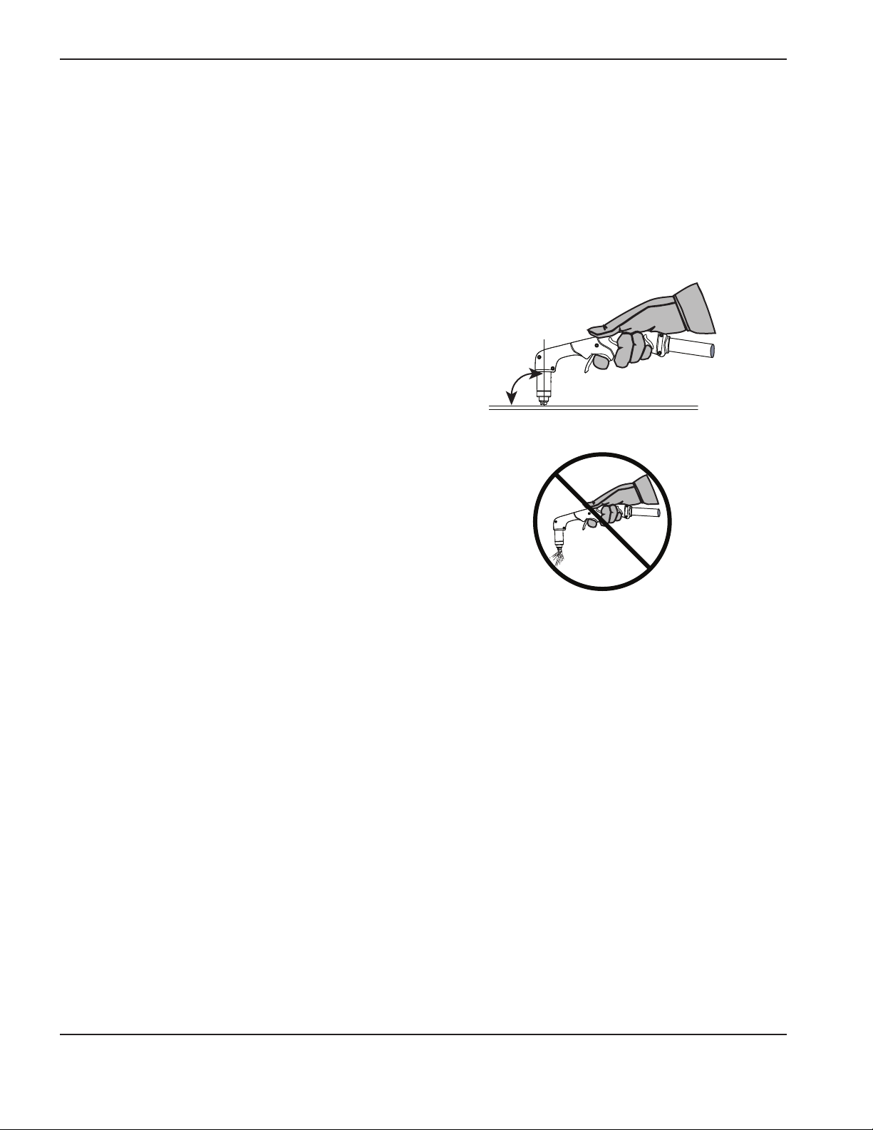
OPERATION
Hand torch cutting hints
• Drag the torch tip lightly along the workpiece to maintain a steady cut.
• While cutting, make sure that sparks exit from the bottom of the workpiece. The sparks should lag slightly
behind the torch as you cut (15° — 30° angle from vertical).
• If sparks spray up from the workpiece, move the torch more slowly, or set the output current higher.
• With hand torches, hold the torch nozzle perpendicular to
the workpiece so that the nozzle is at a 90° angle to the
cutting surface. Observe the cutting arc as the torch cuts.
90°
• If you fire the torch unnecessarily, you will shorten the life of the
nozzle and electrode.
• Pulling, or dragging, the torch along the cut is easier than pushing the torch.
• For straight-line cuts, use a straight edge as a guide. To cut circles, use a template or a radius cutter
attachment (a circle cutting guide). See Section 4, Maintenance and Parts, for part numbers for the Hypertherm
plasma cutting guides for cutting circles and making bevel cuts.
3-18 Duramax Retrofit Torch Operator Manual
Page 49

Start a cut from the edge of the workpiece
1. With the work clamp attached to the workpiece, hold
the torch nozzle perpendicular (90°) to the edge of the
workpiece.
2. Press the torch’s trigger to start the arc. Pause at the edge
until the arc has cut completely through the workpiece.
OPERATION
3. Drag the torch tip lightly across the workpiece to proceed
with the cut. Maintain a steady, even pace.
Duramax Retrofit Torch Operator Manual 3-19
Page 50
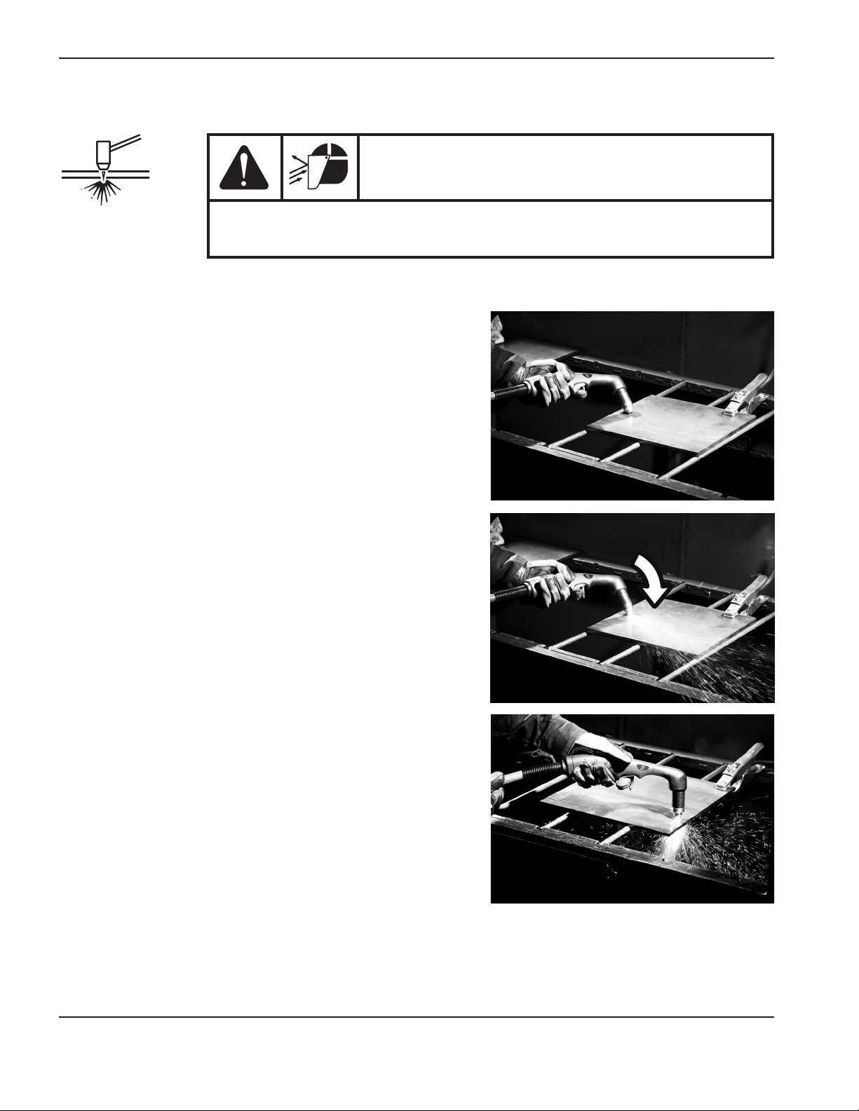
OPERATION
Pierce a workpiece
SPARKS AND HOT METAL CAN INJURE EYES AND BURN SKIN. When firing
the torch at an angle, sparks and hot metal will spray out from the nozzle.
Point the torch away from yourself and others.
1. With the work clamp attached to the workpiece, hold the
torch at an approximate 30° angle to the workpiece with the
torch tip within 1.5 mm (1/16 inch) of the workpiece before
firing the torch.
WARNING
2. Fire the torch while still at an angle to the workpiece. Slowly
rotate the torch to a perpendicular (90°) position.
3. Hold the torch in place while continuing to press the trigger.
When sparks exit below the workpiece, the arc has pierced
the material.
4. When the pierce is complete, dragthe nozzle lightly along the
workpiece to proceed with the cut.
3-20 Duramax Retrofit Torch Operator Manual
Page 51

OPERATION
Gouge a workpiece
WARNING
SPARKS AND HOT METAL CAN INJURE EYES AND BURN SKIN. When firing
the torch at an angle, sparks and hot metal will spray out from the nozzle.
Point the torch away from yourself and others.
1. Hold the torch so that the torch tip is within 1.5 mm (1/16 inch) from the workpiece before firing the torch.
2. Hold the torch at a 45° angle to the workpiece with a small gap
between the torch tip and the workpiece. Press the trigger to
obtain a pilot arc. Transfer the arc to the work piece.
45°
Di rec tion of travel
3. Maintain an approximate 45° angle to the workpiece as you feed
into the gouge. Push the plasma arc in the direction of the gouge
you want to create. Keep a small distance between the torch
tip and the molten metal to avoid reducing consumable life or
damaging the torch.
Changing the torch’s angle changes the dimensions of the
gouge.
Duramax Retrofit Torch Operator Manual 3-21
Page 52

OPERATION
General guidelines for gouging
The following actions have the stated effects on the gouge profile:
• Increasing the speed of the torch will decrease width and decrease depth.
• Decreasing the speed of the torch will increase width and increase depth.
• Increasing the standoff of the torch will increase width and decrease depth.
• Decreasing the standoff of the torch will decrease width and increase depth.
• Increasing the angle of the torch (more vertical) will decrease width and increase depth.
• Decreasing the angle of the torch (less vertical) will increase width and decrease depth.
• Increasing the current of the power supply will increase width and increase depth.
• Decreasing the current of the power supply will decrease width and decrease depth.
Common hand-cutting faults
The torch does not cut completely through the workpiece. The causes can be:
• The cut speed is too fast.
• The consumables are worn.
• The metal being cut is too thick for the selected amperage.
• Gouging consumables are installed instead of drag-cutting consumables.
• The work clamp is not attached properly to the workpiece.
• The gas pressure or gas flow rate is too low.
Cut quality is poor. The causes can be:
• The metal being cut is too thick for the amperage.
• The wrong consumables are being used (gouging consumables are installed instead of drag-cutting
consumables, for example).
• You are moving the torch too quickly or too slowly.
The arc sputters and consumables life is shorter than expected. The cause can be:
• Moisture in the gas supply.
• Incorrect gas pressure.
• Consumables incorrectly installed.
3-22 Duramax Retrofit Torch Operator Manual
Page 53

OPERATION
Using the machine torch
Since the Powermax with a machine torch can be used with a wide variety of cutting tables, track burners, pipe bevelers,
and so on, you will need to refer to the manufacturer’s instructions for specifics on operating the machine torch in
your configuration. However, the information in the following sections will help you optimize cut quality and maximize
consumable life.
Ensure the torch and table are set up correctly
• Use a square to align the torch at right angles to the workpiece in two dimensions.
• The torch may travel more smoothly if you clean, check and “tune” the cutting table’s rails and drive system.
Unsteady machine motion can cause a regular, wavy pattern on the cut surface.
• Ensure that the torch does not touch the workpiece during cutting. Contact with the workpiece can damage the
shield and nozzle and affect the cut surface.
Understand and optimize cut quality
There are several factors to consider in cut quality:
• Cut angle — The degree of angularity of the cut edge.
• Dross — The molten material that solidifies on the top or bottom of the workpiece.
• Straightness of the cut surface — The cut surface can be concave or convex.
The following sections explain how these factors can affect cut quality.
Cut or bevel angle
• A positive cut angle, or bevel, results when more material is removed from the top of the cut than from the
bottom.
• A negative cut angle results when more material is removed from the bottom of the cut.
Duramax Retrofit Torch Operator Manual 3-23
Page 54

OPERATION
Problem
Negative cut angle
Square cut
Positive cut angle
Note: The squarest cut angle will be on the right side with respect to the forward motion of the torch. The left side
will always have some degree of bevel.
To determine whether a cut-angle problem is being caused by the plasma system or the drive system, make a test cut
and measure the angle of each side. Next, rotate the torch 90° in its holder and repeat the process. If the angles are the
same in both tests, the problem is in the drive system.
If a cut-angle problem persists after “mechanical causes” have been eliminated (see “Ensure the torch and table are set
up correctly” on the previous page), check the torch-to-work distance, especially if the cut angles are all positive or all
negative. Also consider the material being cut: if the metal is magnetized or hardened, you are more likely to experience
cut angle problems.
Cause
The torch is too low.
The torch is too high.
Solution
Raise the torch; or if you are using
a torch height control, increase the
arc voltage.
Lower the torch; or if you are using
a torch height control, decrease the
arc voltage.
3-24 Duramax Retrofit Torch Operator Manual
Page 55

OPERATION
Dross
Some amount of dross will always be present when cutting with air plasma. However, you can minimize the amount and
type of dross by adjusting your system correctly for your application.
Excess dross appears on the top edge of both pieces of the plate when the torch is too low (or voltage is too low when
using a torch height control). Adjust the torch or adjust the voltage in small increments (5 volts or less) until the dross is
reduced.
Low-speed dross forms when the torch’s cutting speed is too slow and the arc angles ahead. It forms as a heavy,
bubbly deposit at the bottom of the cut and can be removed easily. Increase the speed to reduce this type of dross.
High-speed dross forms when the cutting speed is too fast and the arc angles behind. It forms as a thin, linear bead of
solid metal attached very close to the cut. It is more firmly attached to the bottom of the cut than at low speed and is
difficult to remove. To reduce high-speed dross:
• Decrease the cutting speed.
• Decrease the torch-to-work distance.
Note: Dross is more likely to form on warm or hot metal than on cool metal. For example, the first cut in a series
of cuts usually produces the least dross. As the workpiece heats up, more dross can accumulate on
subsequent cuts.
Worn or damaged consumables may produce excess dross.
Straightness of the cut surface
A typical plasma cut surface is slightly concave.
The cut surface may become more concave, or convex. Correct torch height is required to keep the cut
surface acceptably close to straight. Worn consumables also affect the straightness of the cut.
A strongly concave cut surface occurs when the torch-to-work distance is too low. Increase the torch-towork distance to straighten the cut surface.
A convex cut surface occurs when the torch-to-work distance is too great or the cutting current is too high.
First, try lowering the torch, then reduce the cutting current.
Duramax Retrofit Torch Operator Manual 3-25
Page 56

OPERATION
To pierce a workpiece using the machine torch
As with the hand torch, you can start a cut with the machine torch at the edge of the workpiece or by piercing the
workpiece. Piercing will result in a shorter consumable life than with edge starts.
The pierce delay must be sufficiently long that the arc can pierce the material before the torch moves, but not so long
that the arc “wanders” while trying to find the edge of a large hole.
When piercing maximum thicknesses, the ring of dross that forms during the pierce may become high enough to contact
the torch when the torch begins to move after the pierce is complete. Remove the dross if the torch will contact it during
the cut.
Common machine-cutting faults
The torch’s pilot arc will initiate, but will not transfer. Causes can be:
• The work cable is not making good contact with the cutting table or the cutting table is not making good
contact with the workpiece.
• The torch-to-work distance is too large.
The workpiece is not totally penetrated, and there is excessive sparking on the top of the workpiece. Causes can be:
• The consumables are worn and need to be replaced. For optimized performance in a mechanized application,
replace the nozzle and the electrode together.
• The work cable is not making good contact with the cutting table or the cutting table is not making good
contact with the workpiece.
• The current (amperage) is set too low. See “Using the cut charts” on page 3-2 for more information.
• The cut speed is too high. See “Using the cut charts” on page 3-2 for more information.
• The metal being cut exceeds the maximum capacity for the selected amperage.
Dross forms on the bottom of the cut. Causes can be:
• The consumables are worn and need to be replaced. For optimized performance in a mechanized application,
replace the nozzle and the electrode together.
• The cutting speed is not correct. See “Using the cut charts” on page 3-2 for more information.
• The current (amperage) is set too low. See “Using the cut charts” on page 3-2 for more information.
3-26 Duramax Retrofit Torch Operator Manual
Page 57

OPERATION
The cut angle is not square. Causes can be:
• The torch is not square to the workpiece.
• The consumables are worn and need to be replaced. For optimized performance in a mechanized application,
replace the nozzle and the electrode together.
• The direction of the torch travel is incorrect. The high-quality cut is always on the right with respect to the
forward motion of the torch.
• The distance between the torch and the workpiece is not correct.
• The cutting speed is not correct. See “Using the cut charts” on page 3-2 for more information.
The consumables’ life is shortened. Causes can be:
• The arc current, arc voltage, travel speed, and other variables are not set as recommended in the cut charts.
• Firing the arc in the air (beginning or ending the cut off of the plate surface). Starting at the edge is acceptable
as long as the arc makes contact with the workpiece when started.
• Starting a pierce with an incorrect torch height. Refer to the cut charts for the specific initial pierce height.
Duramax Retrofit Torch Operator Manual 3-27
Page 58

OPERATION
3-28 Duramax Retrofit Torch Operator Manual
Page 59

Section 4
Maintenance and parts
Perform routine maintenance ......................................................................................................................................................................... 4-2
Inspect the consumables ................................................................................................................................................................................ 4-3
Hand torch replacement parts – Duramax HRT
Machine torch replacement parts – Duramax MRT
Accessory parts................................................................................................................................................................................................. 4-6
2 ....................................................................................................................................................................................
2 ............................................................................................................................................................................
4-4
4-5
Duramax Retrofit Torch Operator Manual 4-1
Page 60

MAINTENANCE AND pArTs
Perform routine maintenance
Disconnect the electrical power before you perform any maintenance. Allwork
that requires removal of the power supply cover must be performed by a
qualified technician.
DANGER
ELECTRIC SHOCK CAN KILL
Every use:
AC
V
Check indicator lights and fault icons.
Correct any fault conditions.
Every 3 months:
Replace any damaged labels.
Inspect the power cord and
plug. Replace if damaged.
Inspect the
consumables for
proper installation
and wear.
Inspect the trigger for
damage. Inspect the
torch body for cracks and
exposed wires. Replace
any damaged parts.
Inspect the torch lead.
Replace if damaged.
Every 6 months:
Clean the inside of the power supply
Or
with compressed air or a vacuum.
4-2 Duramax Retrofit Torch Operator Manual
Page 61

Inspect the consumables
Part Inspect Action
Shield or
deflector
The center hole for
roundness.
The gap between the
shield and the nozzle for
accumulated debris.
MAINTENANCE AND pArTs
Replace the shield if the hole is no
longer round.
Remove the shield and clean away
any material.
Nozzle
Electrode
Swirl ring
Torch o-ring
The center hole for
roundness.
Good Worn
Max. 1.5 mm (1/16 in)
The surface inside the swirl
ring for damage or wear and
the gas holes for blockages.
The surface for damage,
wear, or a lack of lubrication.
Replace nozzle if the center hole is
not round.
Replace electrode if the surface is
worn or the pit depth is greater than
1/16 inch (1.6mm) deep.
Replace swirl ring if the surface is
damaged or worn or any of the gas
holes are blocked.
If the o-ring is dry, lubricate it and the
threads with a thin layer of silicone
lubricant. If the o-ring is worn or
damaged, replace it.
Duramax Retrofit Torch Operator Manual 4-3
Page 62

MAINTENANCE AND pArTs
Hand torch replacement parts – Duramax HRT
Coupler
Cap-sensor
switch
Pilot arc wire
terminal screw
Torch body
O-ring
Safety trigger
and spring
Trigger start
switch
2
Torch handle
Torch lead
Handle
screws
The HRT2 torch assembly can be replaced, or individual component parts can be replaced. The HRT2 torch assembly
includes a variety of Duramax consumables.
Part number Description
005252 Trigger start switch
058519 O-ring
075504 Pilot arc wire terminal screw
075714 Handle screws, #4 x 1/2 slotted TORX pan head, S/B
128926* Kit: Quick disconnect repair
228954 Kit: Duramax 75°/HRT2 torch handle replacement
228719 Kit: Duramax 75°/HRT2 cap-sensor switch replacement
228721 Kit: Safety trigger with spring replacement
228924* Kit: HRT2 lead replacement, 7.6 m (25 ft)
228925* Kit: HRT2 lead replacement, 15.2 m (50 ft)
228926** Kit: HRT2 lead replacement, 7.6 m (25 ft) – without quick disconnect
228927** Kit: HRT2 lead replacement, 15.2 m (50 ft) – without quick disconnect
228916* Kit: HRT2 torch assembly with 7.6 m (25 ft) lead
228917* Kit: HRT2 torch assembly with 15.2 m (50 ft) lead
228918** Kit: HRT2 torch assembly with 7.6 m (25 ft) lead – without quick disconnect
228919** Kit: HRT2 torch assembly with 15.2 m (50 ft) lead – without quick disconnect
228950 Kit: HRT2 torch main body replacement, coupler with 12.7 mm (1/2 in.) threads
* For use with Powermax600, Powermax800, Powermax900, MAX42, and MAX43 CSA systems.
** For use with Powermax600 CE systems.
4-4 Duramax Retrofit Torch Operator Manual
Page 63

MAINTENANCE AND pArTs
Machine torch replacement parts – Duramax MRT
Consumables
Pilot arc wire
terminal screw
Mounting
sleeve
Coupler
Torch bodyO-ring
Positioning sleeve
Gear rack (32 pitch)
Cap-sensor
switch
2
Strain relief nut
Strain relief body
Wire connector for
cap-sensor switch
Torch lead
The MRT2 torch assembly can be replaced, or individual component parts can be replaced. The MRT2 torch assembly
includes a variety of Duramax consumables.
Part number Description
058519 O-ring
075504 Pilot arc wire terminal screw
128926* Kit: Quick disconnect repair
228720 Kit: Cap-sensor switch replacement
228735 Kit: M65/M65m/M85/M85m/MRT2 front mounting sleeve
228736 Kit: M65/M65m/M85/M85m/MRT2 adapter ring (coupler)
228737 Kit: M65/M85/MRT2 positioning sleeve
228738 Kit: M65/M85/MRT2 removable gear rack
228928* Kit: MRT2 lead replacement, 7.6 m (25 ft)
228929* Kit: MRT2 lead replacement, 15.2 m (50 ft)
228930** Kit: MRT2 lead replacement, 7.6 m (25 ft) – without quick disconnect
228931** Kit: MRT2 lead replacement, 15.2 m (50 ft) – without quick disconnect
228920* Kit: MRT2 torch assembly with 7.6 m (25 ft) lead
228921* Kit: MRT2 torch assembly with 15.2 m (50 ft) lead
228922** Kit: MRT2 torch assembly with 7.6 m (25 ft) lead – without quick disconnect
228923** Kit: MRT2 torch assembly with 15.2 m (50 ft) lead – without quick disconnect
228793 Kit: MRT2 torch main body replacement
* For use with Powermax600, Powermax800, Powermax900, MAX42, and MAX43 CSA systems.
** For use with Powermax600 CE systems.
Duramax Retrofit Torch Operator Manual 4-5
Page 64

MAINTENANCE AND pArTs
Accessory parts
Part number Description
024548 Leather torch sheathing, 7.5 m (25 ft)
127102 Basic plasma (circles and lines) cutting guide
027668 Deluxe plasma (circles and lines) cutting guide
4-6 Duramax Retrofit Torch Operator Manual
 Loading...