

Page 1
HyDefinition
®
HD4070
Plasma Arc Cutting / Marking System
Product Configuration Manual
803770 – Revision 1
4070.97
Page 2

HD4070
Product Configuration Manual
(P/N 803770)
Revision 1 – December, 2002
© Copyright 2002 Hypertherm, Inc.
All Rights Reserved
Hypertherm, HyDefinition and HT are trademarks of Hypertherm, Inc.
and may be registered in the United States and/or other countries
Hypertherm, Inc.
Hanover, NH USA
www.hypertherm.com
Page 3

Hypertherm, Inc.
Etna Road, P.O. Box 5010
Hanover, NH 03755 USA
603-643-3441 Tel (Main Office)
603-643-5352 Fax (All Departments)
800-643-9878 Tel (Technical Service)
800-737-2978 Tel (Customer Service)
Hypertherm Automation, LLC
5 Technology Drive
West Lebanon, NH 03755 USA
603-298-7970 Tel
603-298-7977 Fax
Hypertherm Plasmatechnik, GmbH
Technologiepark Hanau
Rodenbacher Chaussee 6
63457 Hanau-Wolfgang, Deutschland
49 6181 58 2100 Tel
49 6181 58 2134 Fax
49 6181 58 2123 (Technical Service)
Hypertherm (S) Pte Ltd
No. 19 Kaki Bukit Road 2
K.B. Warehouse Complex
Singapore 417847, Republic of Singapore
65 6 841 2489 Tel
65 6 841 2490 Fax
65 6 841 2489 (Technical Service)
Japan
1952-14 Yata-Natsumegi
Mishima City, Shizuoka Pref.
411-0801 Japan
81 0 559 75 7387 Tel
81 0 559 75 7376 Fax
Hypertherm UK, Ltd
9 Berkeley Court, Manor Park
Runcorn, Cheshire, England WA7 1TQ
44 1928 579 074 Tel
44 1928 579 604 Fax
France
15 Impasse des Rosiers
95610 Eragny, France
00 800 3324 9737 Tel
00 800 4973 7329 Fax
Hypertherm S.r.l.
Via Torino 2
20123 Milano, Italia
39 02 725 46 312 Tel
39 02 725 46 400 Fax
39 02 725 46 314 (Technical Service)
Hypertherm Europe B.V.
Vaartveld 9
4704 SE Roosendaal, Nederland
31 165 596908 Tel
31 165 596901 Fax
Technical Service:
00 800 49 73 7843 – toll-free in Europe
31 165 596900 Tel
Hypertherm Brasil Ltda.
Rua Visconde de Santa Isabel, 20 – Sala 611
Vila Isabel, RJ
Brasil CEP 20560-120
55 21 2278 6162 Tel
55 21 2578 0947 Fax
3/27/03
Page 4

0
HD4070 Product Configuration Manual 1-1
Section 1
SPECIFICATIONS
In this section:
Description................................................................................................................................................................1-2
General ............................................................................................................................................................1-2
Power Supply ..................................................................................................................................................1-2
Machine Torch..................................................................................................................................................1-2
Off-V alve Assembly..........................................................................................................................................1-2
Gas Console ....................................................................................................................................................1-2
Ignition Console ...............................................................................................................................................1-2
Options.............................................................................................................................................................1-3
Specifications............................................................................................................................................................1-7
System Requirements......................................................................................................................................1-7
Power Supply...................................................................................................................................................1-8
Gas Console Assembly – 078085..................................................................................................................1-10
Ignition Console Assembly – 078088.............................................................................................................1-11
Off-Valve Assembly – 129563........................................................................................................................1-12
Machine Torch Assembly with Leads.............................................................................................................1-13
Page 5

0
1-2 HD4070 Product Configuration Manual
SPECIFICATIONS
Description
General
The HD4070 is a fully automated 200 amp HyDefinition plasma cutting/marking system that requires minimal input
and adjustment by the operator. Using the HD4070 display touch screen (or CNC), the operator enters the material
and thickness to be cut. The HD4070 system automatically selects and adjusts the power and gas required to
optimize cutting, including amperage, gas type and gas flow rates.
Power Supply
The power supply houses two 100-amp, 15 kHz choppers to produce up to 200A of constant current DC output.
The HD4070 power supply provides the torch the energy to cut 1/2" (12.7 mm) mild steel at up to 90 ipm
(2286 mm/min.).
Machine Torch
The machine torch can cut 1/2 inch (12.7mm) mild steel at 90 ipm (2286 mm/min.). The maximum production
cutting capability of the torch is 1 inch (25 mm). To achieve consumable long life, all cuts must begin and end
on the plate surface.
Off-Valve Assembly
The off-valve assembly consists of 5 solenoid valves, a manifold block and a wiring harness with connector. The
assembly interfaces with the machine torch, the ignition console and the gas console.
Gas Console
The gas console manages all incoming gasses for selection and flow rates and is controlled by the HD4070 power
supply. The gas console includes motor valves, solenoid valves, check valves and pressure trans-ducers all
mounted on a single manifold assembly. The manifold significantly reduces gas leaks by eliminating the use of
flexible hose. The gas console also houses 2 relay PC boards and a control PC board.
Ignition Console
The ignition console generates a high voltage, high frequency signal and couples it to the cathode lead and pilot
arc lead. The ignition console is fully electronic eliminating the need for periodic maintenance.
Page 6
0
HD4070 Product Configuration Manual 1-3
SPECIFICATIONS
HD4070 System with 2-Torch Option
Options
• 2-Torch Option – The HD4070 plasma cutting/marking system has the ability to support 2 torches operated
from a single power supply and gas console. When one torch is selected for cutting the second torch is in
the off mode. This allows the operator to configure the system for two different processes (i.e. 100 amp
consumables installed in one torch and 200 amp consumables installed in the second torch). The operator
selects torch number-1 or torch number-2 from the HD4070 display (or CNC).
Note: Atorch receptacle plug must be used if a two torch system is running in single torch mode.
Single torch mode is when a table is loaded with plate material and one torch is doing all the
cutting or marking.
Dual torch mode is when one torch is performing one operation and the second torch is
performing another operation on the same plate material.
4070.97
Page 7
0
1-4 HD4070 Product Configuration Manual
SPECIFICATIONS
• Integrated Command THC Option – The Hypertherm Integrated Command THC takes full advantage of
the HD4070 automated capabilities. When the operator enters the material and thickness to be cut into the
HD4070 display touch screen (or CNC), the Integrated Command THC automatically adjusts the torch
settings required for the specific process, including arc volts, torch standoff, initial pierce height and pierce
time delay. The Integrated Command THC system uses the plasma arc voltage to control the physical
stand-off (distance) between the torch and workpiece during plasma arc cutting. Initial height sensing (IHS)
is accomplished by ohmic contact sensing or by limited force stall detection.
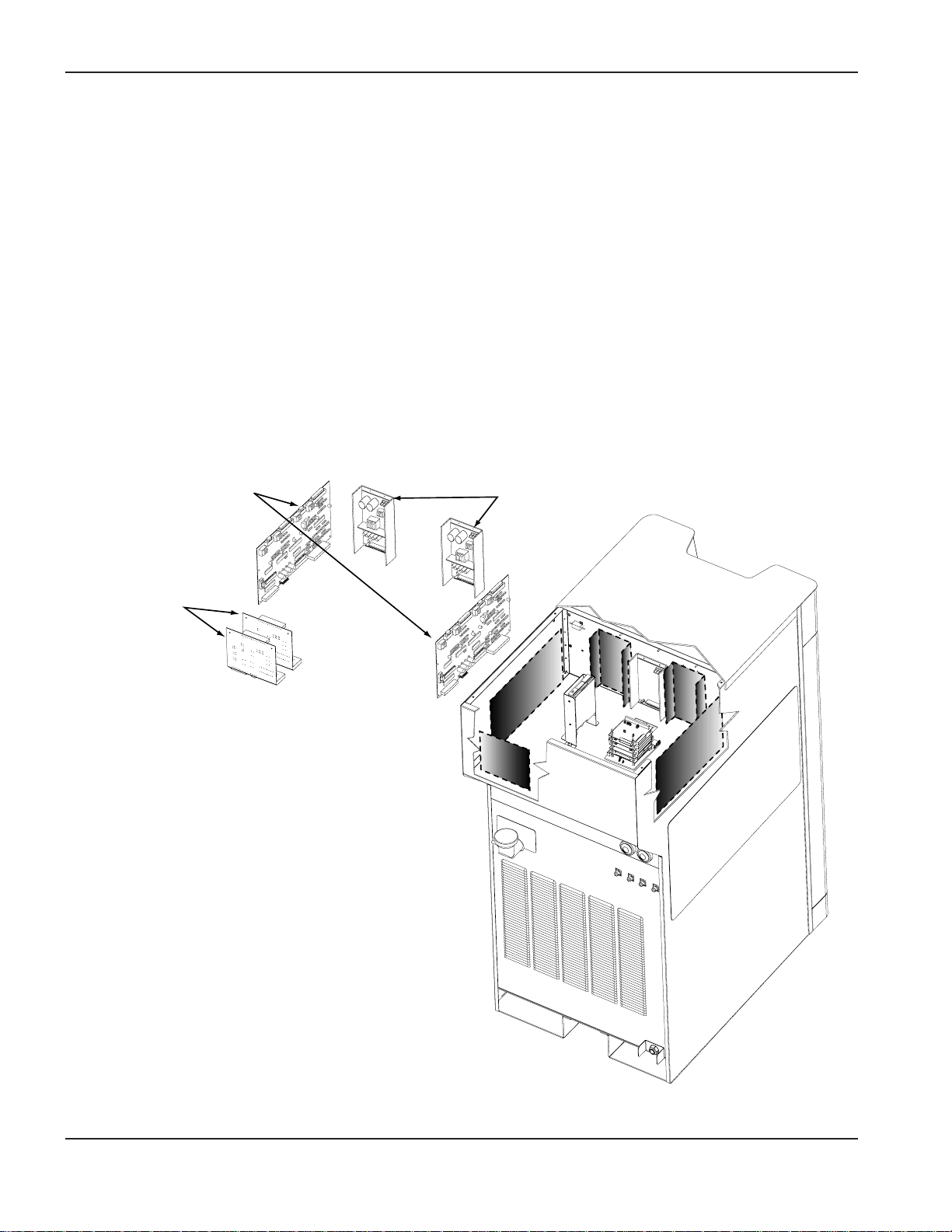
HD4070 power supplies that are equipped with the Integrated Command THC option include the THC motor
drive board, the THC control PC board and THC power supply required for torch lifter operation and control.
One or two Command THC options can be specified, depending on how many torches are installed with the
system.
Power Supply with Command THC Option for 2-Torch System
THC Motor
Drive Boards
THC Control
PC Boards
THC Power
Supplies
4070.48
Page 8

0
HD4070 Product Configuration Manual 1-5
SPECIFICATIONS
The Integrated Command THC option includes the X-Y lifter, torch mounting block and the related cables.
A torch breakaway (collision sensor) is also available to protect the torch, lifter and X-Y table. Adjustable air
pressure locks the torch to the THC lifter assembly. Upon side impact, the breakaway releases from the lock
position and allows the torch to float.
THC Cables
THC X-Y Lifter
THC Torch
Breakaway Option
4070.45A
Integrated Command THC Lifter, Cables and Breakaway
Page 9
0
1-6 HD4070 Product Configuration Manual
SPECIFICATIONS
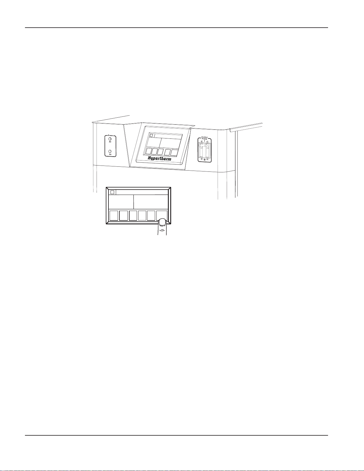
• Touch Screen Display Option – The HD4070 display is a touch screen interface, providing all system
control functions and plasma process information at a single location. The power supply may be ordered
with the display mounted in the front panel. Kits are also available for mounting the display remotely.
4070.23B
1
3
T
O
R
C
H
1
N
O
P
I
L
O
T
A
R
C
S
T
A
I
N
L
E
S
S
S
T
E
E
L
N
E
W
P
R
O
C
E
S
N
E
X
T
A
U
T
O
M
A
N
T
H
C
A
R
C
V
O
L
T
A
R
C
V
O
L
T
O
V
E
R
R
I
D
E
V
O
L
T
S
:
1
4
4
.
5
V
S
E
T
A
R
C
V
O
L
T
S
:
1
4
2
.
0
V
I
N
L
E
T
G
A
S
:
H
3
5
N
2
C
U
T
T
I
N
G
S
P
E
E
D
:
6
5
I
P
M
3
/
4
I
N
2
0
0
A
M
P
S
S
T
A
N
D
O
F
F
:
0
.
0
5
0
I
N
+
+
_
_
C
N
C
TORCH 1
READY
STAINLESS STEEL
NEW
PROCESS
NEXT
AUTO
MAN
THC
OVERRIDE VOLTS: 144.5 V
SET ARC VOLTS: 142.0 V
INLET GAS: H35 N2
CUTTING SPEED: 65 IPM
3/4 IN
200 AMPS
STANDOFF: 0.050 IN
ARC
VOLT
++
ARC
VOLT
_ _
13
HELP
Display Touch Screen Option
Warning: The HD4070 system can only support one touch screen display, either local or remote. The
installation of two displays on one system may cause malfunctions or damage.
Page 10
1
HD4070 Product Configuration Manual 1-7
SPECIFICATIONS
Specifications
System Requirements
Gas Quality and Pressure Requirements
Quality Pressure + 5% Flow Rate
O2Oxygen 99.5% pure (liquid gas recommended) 120 psi 133 scfh (3780 l/h)
Clean, dry, oil-free 8.3 bar / 827 kPa
N2Nitrogen 99.99% pure (liquid gas recommended) 120 psi 142 scfh 4020 l/h
Clean, dry, oil-free 8.3 bar / 827 kPa
Air Clean, dry, oil-free 120 psi 140 scfh 3960 l/h
8.3 bar / 827 kPa
CH4Methane 93% pure 120 psi 188 scfh 5340 l/h
8.3 bar / 827 kPa
H5 Argon-Hydrogen 99.995% pure (liquid gas recommended) 120 psi 122 scfh 3420 l/h
(H5=5% Hydrogen, 95% Argon) 8.3 bar / 827 kPa
H35 Argon-Hydrogen 99.995% pure (liquid gas recommended) 120 psi 146 scfh 4140 l/h
(H35=35% Hydrogen, 65% Argon) 8.3 bar / 827 kPa
*
CO2Carbon-Dioxide 99.5% pure 120 psi 113 scfh 3180 l/h
8.3 bar / 827 kPa
Mild Steel Stainless Steel Aluminum
Gas Types Plasma Shield Plasma Shield Plasma Shield
Marking N
2
N
2
H5 N
2
H5 N
2
Cutting 30 A O
2
O2& N
2
Air Air Air Air
Cutting 70 A O
2
O2& N
2
H35 & N
2
N
2
Air CH4& Air
Cutting 100 A to 200 A O
2
O2& N
2
H35 & N
2
N
2
H35 & N
2
N
2
*
CO2is not currently used on the HD4070 and there is no need to install the gas line.
Page 11

1
1-8 HD4070 Product Configuration Manual
SPECIFICATIONS
Power Supply
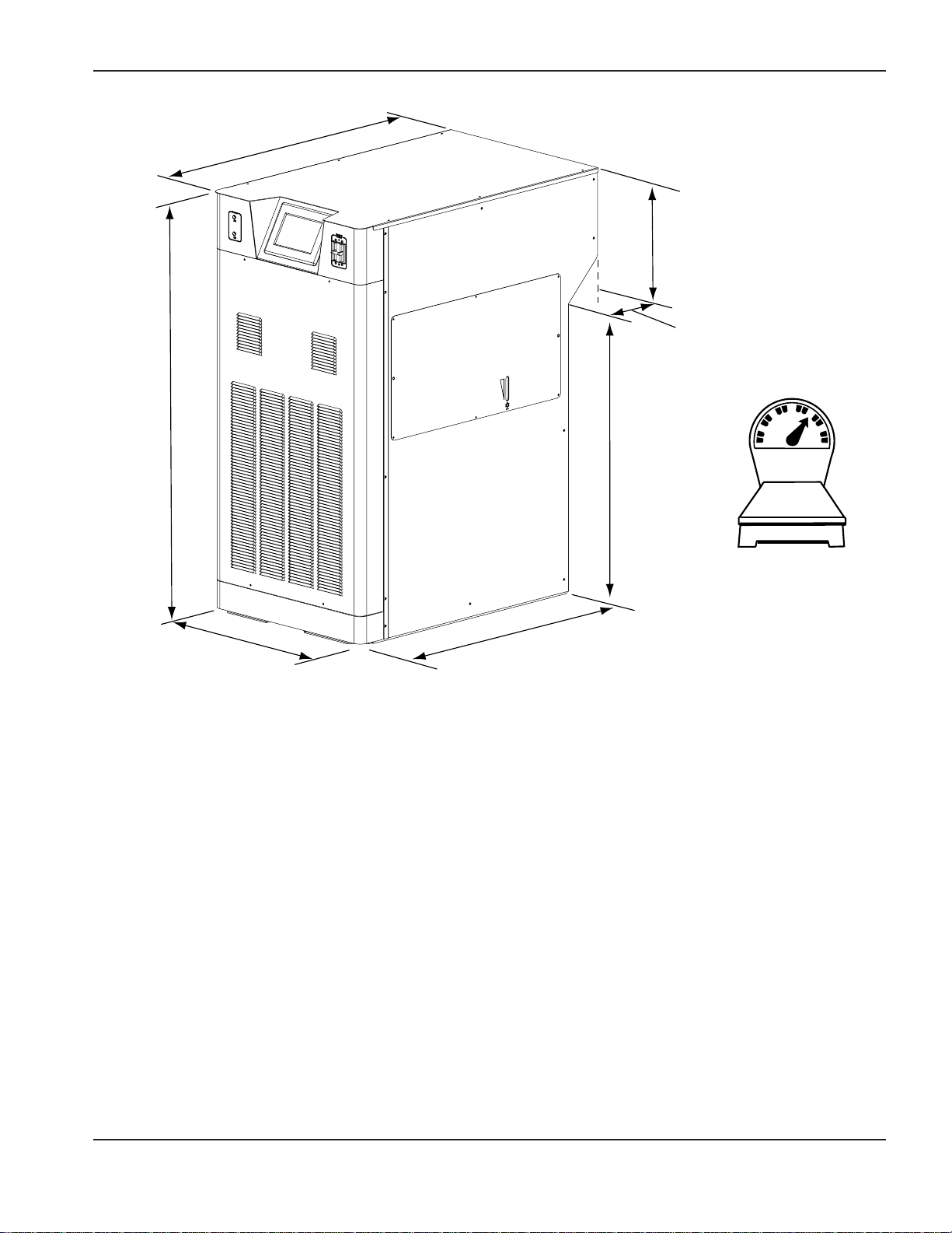
• Place the power supply in an area that is free of excessive moisture, has proper ventilation, and is relatively
clean. Allow room at the sides and rear of the power supply for servicing.
• Cooling air is drawn in through the front panel grating and is exhausted through the rear of the unit by a
cooling fan. Allow a minimum of 12 inches (305 mm) for air flow.
• Maximum distance to the ignition console = 150 feet (46 m).
• Maximum distance to the gas console = 150 feet (46 m).
General
Maximum OCV (U0) 311 VDC
Maximum Output Current (I2) 200 amps
Output Voltage (U2) 85 - 200 VDC
Duty Cycle Rating (X) 100% @ 40 kw, 104°F (40°C)
Ambient Temperature/Duty Cycle Power supplies will operate between +14° and 104°F
( -10°C and +40°C)
Power Factor(cosϕ) 0.98 @ 200A DC output
Cooling Forced Air (Class F)
Input Power (Input Voltage (U1) X Input Current (I1X 1.73)
200 VAC, 3ph, 50-60 Hz, 125A
220 VAC, 3ph, 50-60 Hz, 113A
240 VAC, 3ph, 60 Hz, 103A
400 VAC CE, 3ph, 50-60 Hz, 62A
440 VAC, 3ph, 50-60 Hz, 56A
480 VAC, 3ph, 60 Hz, 52A
600 VAC, 3ph, 60 Hz, 41A
Page 12
0
HD4070 Product Configuration Manual 1-9
SPECIFICATIONS
50.5"
1283 mm
39.4"
1001 mm
34.9"
886 mm
15.6"
396 mm
5"
127 mm
1068 lb
484.9 kg
24.25"
616 mm
34.4"
874 mm
4070.42
Page 13
0
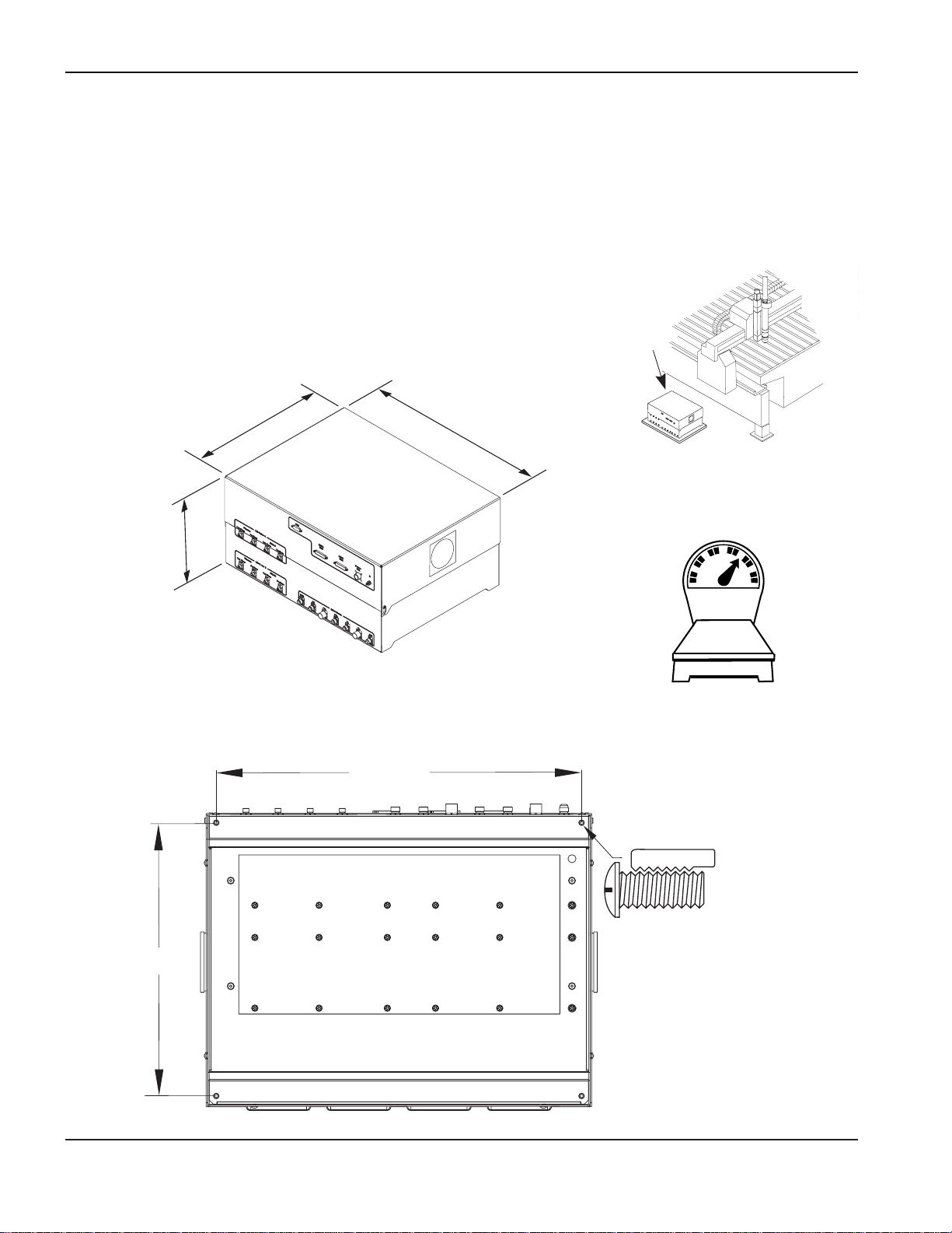
1-10 HD4070 Product Configuration Manual
94 lb
42.7 kg
11.625"
295 mm
18.75"
476 mm
24.75"
629 mm
1/4-20
22.75" / 578 mm
17.0"
432 mm
4070.20A
SPECIFICATIONS
Gas Console Assembly – 078085
• Position the gas console near the cutting table. Allow room to open the hinged top for servicing.
• Venting air is drawn in through fans on both sides and is exhausted through the front of the unit.
• Maximum distance from the power supply = 150 feet (46 m).
• Maximum distance to the off-valve assembly = 100 feet (31 m).
Page 14
0
HD4070 Product Configuration Manual 1-11
4070.19A
0
0
1.25" / 32 mm
11.0"
279 mm
9.75"
248 mm
0.28"
7 mm
1.25"
32 mm
10.63" / 270 mm
4070.21
6.25"
159 mm
11.25"
286 mm
12"
305 mm
20.5 lb
9.3 kg
Horizontal Mounting
Vertical Mounting
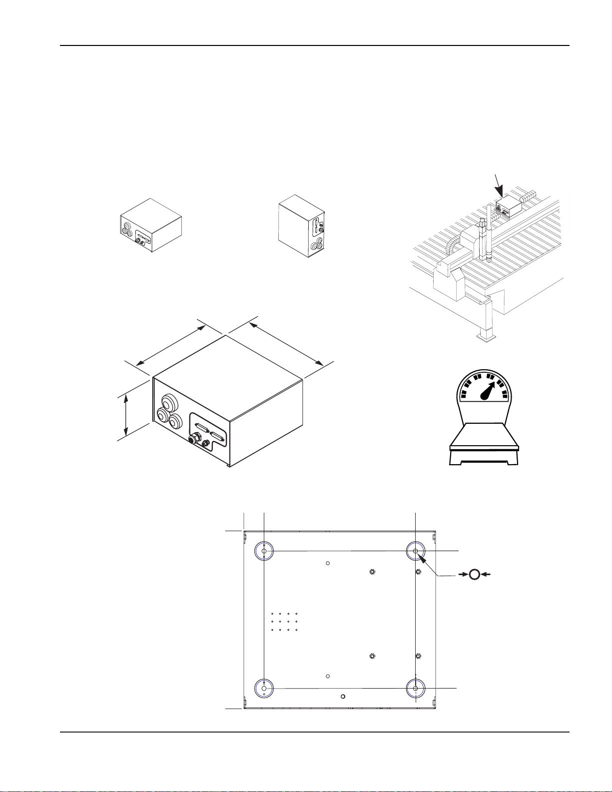
SPECIFICATIONS
Ignition Console Assembly – 078088
• Mount the ignition console near the torch. Allow room to remove the top for servicing.
• Mount the ignition console in the horizontal or the vertical position as shown below.
• Maximum distance to the torch = 15 feet (4.5 m).
Page 15

0
1-12 HD4070 Product Configuration Manual
4070.18A
A
A
A - A
6.18"
157 mm
1.18"
30 mm
0.187"
4.7 mm
0.75"
19 mm
6.5"
165 mm
3"
76 mm
2.75"
70 mm
2.5 lb
1.1 kg
SPECIFICATIONS
Off-Valve Assembly – 129563
• Mount the off-valve assembly near the torch.
• Maximum distance from the torch = 4 feet (1.2 m).
Page 16
0
HD4070 Product Configuration Manual 1-13
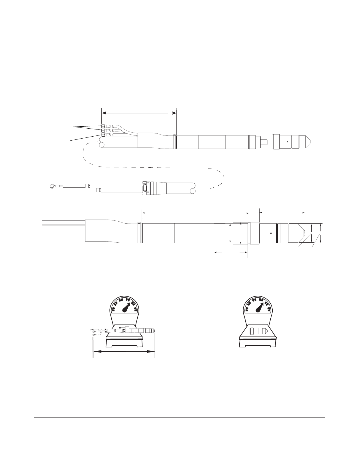
SPECIFICATIONS
Machine Torch Assembly with Leads
• Assembly includes leads, torch and consumables.
• 128500 6 ft / 2 m
128501 10 ft / 3 m
128502 15 ft / 4.5 m
Without Coolant
To off-valve
assembly
Plasma Gas
Vent
4 ft / 1.2 m
14.7 lb
6.7 kg
15 ft / 4.5 m
10.86"
(276 mm)
2"
(51 mm)
(89 mm)
3.5"
2.25"
(57 mm)
1.05"
(27
mm)
2 lb
0.9 kg
4.65"
(118 mm)
1.88"
(48 mm)
1.98"
(50 mm)
4070.44
Page 17

0
1-14 HD4070 Product Configuration Manual
SPECIFICATIONS
Page 18

0
HD4070 Product Configuration Manual 2-1
Section 2
ORDERING
In this section:
Ordering the HD4070 System...................................................................................................................................2-2
HD4070 Power Supply with NO Integrated Command THC Option Order Form A ..................................................2-3
HD4070 Power Supply with ONE Integrated Command THC Option Order Form B................................................2-5
HD4070 Power Supply with TWO Integrated Command THC Option Order Form C...............................................2-7
HD4070 Components, Cables and Hoses for 1-Torch Option Order Form D...........................................................2-9
HD4070 Components, Cables and Hoses for 2-Torch Option Order Form E .........................................................2-11
HD4070 Supply Gas Hoses, Regulators & Upgrade Kits Order form F..................................................................2-12
Page 19
0
2-2 HD4070 Product Configuration Manual
ORDERING
Ordering the HD4070 System
Ordering a system can be a complex procedure. The following components are required to operate the HD4070
system:
• Power supply
• Ignition console and connecting cables and hoses
• Gas console and connecting cables and hoses
• Off-Valve Assembly and connecting cables and hoses
• Torch and Lead Assembly
• Machine interface I/O cable to start and control the system from the CNC
Hypertherm offers three major options for the HD4070 system:
• Integrated command Torch Height Control (THC) Option
• 2-Torch option
• Touch screen display
Use the following order forms as required:
Order the HD4070 power supply using Order Form , or . Touch screen display and voltage choices are
found on each of these forms.
When using order Form use Form or to order Components, Cables & Hoses
When using order Form use Form to order Components, Cables & Hoses
When using order Form use Form to order Components, Cables & Hoses
Use order form to order Supply Gas Hoses, Regulators & Upgrade Kits. The upgrade kits are for use with
previously purchased power supplies.
F
E
C
D
B
E
D
A
C
B
A
HD4070 System Configuration
Order Forms
C
Power Supply with 2-THC Option
Use Order Form
B
Power Supply with 1-THC Option
Use Order Form
A
Power Supply with No THC Option
Use Order Form
D
Components, Cables & Hoses for 1-Torch Option
Use Order Form
Components, Cables & Hoses for 2-Torch Option
Use Order Form
E
- OR -
- OR -
Supply Gas Hoses, Regulators & Upgrade Kits
Use Order Form
F
Page 20
Distributor Information:
Customer Information:
480V 240V 400V 200V 440V 220V 600V
60 HZ 60 HZ 50-60 HZ 50-60 HZ 50-60 HZ 50-60 HZ 60 HZ
078087 X –––––– No Display Installed
078134 – X –––––
078089 ––X ––––
078135 –––X –––
078095 ––––X ––
078141 –––––X –
078106 ––––––X
078103 X ––––––
With Display Installed
078149 – X –––––
078092 ––X ––––
078138 –––X –––
078098 ––––X ––
078144 –––––X –
078109 ––––––X
128526 10 ft.(3 m)
128527 20 ft.(6.1 m)
128528 25 ft.(7.6 m)
128529 30 ft.(9.1 m)
128530 40 ft.(12.2 m)
128531 50 ft.(15.2 m)
128532 75 ft.(22.9 m)
128533 100 ft.(30.5 m)
128534 150 ft.(45.7 m)
Remote Display Option Kit
Installed Display can be removed
and mounted at a remote location
with a remote cable kit. See Order
form or instruction manual
parts list for kit numbers.
- Use Order Form or
2
18
through
Warning: Each power supply can only support one display.
Installation of two displays with one power supply may result in
malfunction or damage.
19
Use Order Form
F
ED
F
HYPERTHERM – HD4070 Power Supply with NO Integrated Command THC Option – Order Form
A
1
0
Voltage
1
3
REPEA
NEW
T
PROCESS
PREVIOUS
PROCESS
S
E
T
U
P
Page 21

Page 22

0
Distributor Information:
Customer Information:
480V 240V 400V 200V 440V 220V 600V
60 HZ 60 HZ 50-60 HZ 50-60 HZ 50-60 HZ 50-60 HZ 60 HZ
078087 X –––––– No Display Installed
078134 – X –––––
078089 ––X ––––
078135 –––X –––
078095 ––––X ––
078141 –––––X –
078106 ––––––X
078103 X ––––––
With Display Installed
078149 – X –––––
078092 ––X ––––
078138 –––X –––
078098 ––––X ––
078144 –––––X –
078109 ––––––X
128526 10 ft.(3 m)
128527 20 ft.(6.1 m)
128528 25 ft.(7.6 m)
128529 30 ft.(9.1 m)
128530 40 ft.(12.2 m)
128531 50 ft.(15.2 m)
128532 75 ft.(22.9 m)
128533 100 ft.(30.5 m)
128534 150 ft.(45.7 m)
Remote Display Option Kit
Installed Display can be removed
and mounted at a remote location
with a remote cable kit. See Order
form or instruction manual
parts list for kit numbers.
- Use Order Form or
2
18
through
Warning: Each power supply can only support one display.
Installation of two displays with one power supply may result in
malfunction or damage.
19
Use Order Form
F
ED
F
HYPERTHERM – HD4070 Power Supply with NO Integrated Command THC Option – Order Form
A
1
Voltage
1
3
REPEA
NEW
T
PROCESS
PREVIOUS
PROCESS
S
E
T
U
P
Page 23

Page 24

Distributor Information:
Customer Information:
480V 240V 400V 200V 440V 220V 600V
60 HZ 60 HZ 50-60 HZ 50-60 HZ 50-60 HZ 50-60 HZ 60 HZ
078087 X –––––– No Display Installed
078134 – X –––––
078089 ––X ––––
078135 –––X –––
078095 ––––X ––
078141 –––––X –
078106 ––––––X
078103 X ––––––
With Display Installed
078149 – X –––––
078092 ––X ––––
078138 –––X –––
078098 ––––X ––
078144 –––––X –
078109 ––––––X
128526 10 ft.(3 m)
128527 20 ft.(6.1 m)
128528 25 ft.(7.6 m)
128529 30 ft.(9.1 m)
128530 40 ft.(12.2 m)
128531 50 ft.(15.2 m)
128532 75 ft.(22.9 m)
128533 100 ft.(30.5 m)
128534 150 ft.(45.7 m)
Remote Display Option Kit
Installed Display can be removed
and mounted at a remote location
with a remote cable kit. See Order
form or instruction manual
parts list for kit numbers.
- Use Order Form or
2
18
through
Warning: Each power supply can only support one display.
Installation of two displays with one power supply may result in
malfunction or damage.
19
Use Order Form
F
ED
F
HYPERTHERM – HD4070 Power Supply with NO Integrated Command THC Option – Order Form
A
1
0
Voltage
1
3
REPEA
NEW
T
PROCESS
PREVIOUS
PROCESS
S
E
T
U
P
Page 25

Page 26

Distributor Information:
Customer Information:
480V 240V 400V 200V 440V 220V 600V
60 HZ 60 HZ 50-60 HZ 50-60 HZ 50-60 HZ 50-60 HZ 60 HZ
078087 X –––––– No Display Installed
078134 – X –––––
078089 ––X ––––
078135 –––X –––
078095 ––––X ––
078141 –––––X –
078106 ––––––X
078103 X ––––––
With Display Installed
078149 – X –––––
078092 ––X ––––
078138 –––X –––
078098 ––––X ––
078144 –––––X –
078109 ––––––X
128526 10 ft.(3 m)
128527 20 ft.(6.1 m)
128528 25 ft.(7.6 m)
128529 30 ft.(9.1 m)
128530 40 ft.(12.2 m)
128531 50 ft.(15.2 m)
128532 75 ft.(22.9 m)
128533 100 ft.(30.5 m)
128534 150 ft.(45.7 m)
Remote Display Option Kit
Installed Display can be removed
and mounted at a remote location
with a remote cable kit. See Order
form or instruction manual
parts list for kit numbers.
- Use Order Form or
2
18
through
Warning: Each power supply can only support one display.
Installation of two displays with one power supply may result in
malfunction or damage.
19
Use Order Form
F
ED
F
HYPERTHERM – HD4070 Power Supply with NO Integrated Command THC Option – Order Form
A
1
0
Voltage
1
3
REPEA
NEW
T
PROCESS
PREVIOUS
PROCESS
S
E
T
U
P
Page 27

Page 28

Distributor Information:
Customer Information:
480V 240V 400V 200V 440V 220V 600V
60 HZ 60 HZ 50-60 HZ 50-60 HZ 50-60 HZ 50-60 HZ 60 HZ
078087 X –––––– No Display Installed
078134 – X –––––
078089 ––X ––––
078135 –––X –––
078095 ––––X ––
078141 –––––X –
078106 ––––––X
078103 X ––––––
With Display Installed
078149 – X –––––
078092 ––X ––––
078138 –––X –––
078098 ––––X ––
078144 –––––X –
078109 ––––––X
128526 10 ft.(3 m)
128527 20 ft.(6.1 m)
128528 25 ft.(7.6 m)
128529 30 ft.(9.1 m)
128530 40 ft.(12.2 m)
128531 50 ft.(15.2 m)
128532 75 ft.(22.9 m)
128533 100 ft.(30.5 m)
128534 150 ft.(45.7 m)
Remote Display Option Kit
Installed Display can be removed
and mounted at a remote location
with a remote cable kit. See Order
form or instruction manual
parts list for kit numbers.
- Use Order Form or
2
18
through
Warning: Each power supply can only support one display.
Installation of two displays with one power supply may result in
malfunction or damage.
19
Use Order Form
F
ED
F
HYPERTHERM – HD4070 Power Supply with NO Integrated Command THC Option – Order Form
A
1
0
Voltage
1
3
REPEA
NEW
T
PROCESS
PREVIOUS
PROCESS
S
E
T
U
P
Page 29

Page 30

Page 31

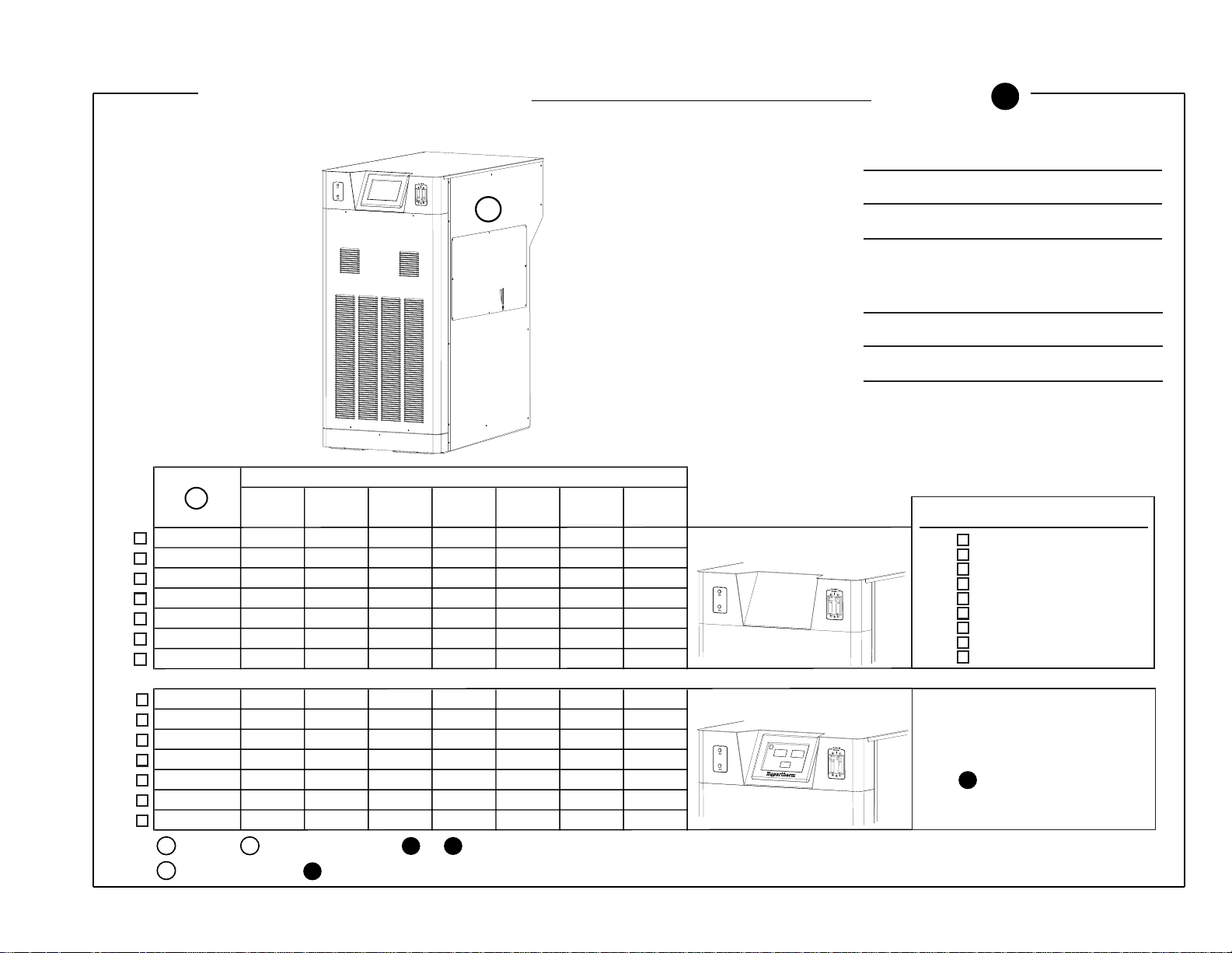
HD4070 Power Supply with ONE Integrated Command THC Option
Use with Order Form
B
20
THC Power
Supply
THC Control
PC Board
Note: These components
are factory installed
1
THC Motor
Drive Board
22
23
Torch and Lead
Assembly
24
4070.46A
21
25
Page 32

HYPERTHERM – HD4070 Power Supply with ONE Integrated Command THC Option – Order Form
B
20
X-Y Lifter - Quantity 1
128606
21
Torch Mounting Block Kit - Quantity 1
128279
25
Torch Breakaway Kit Option - Quantity 1
128281
128526 10 ft.(3 m)
128527 20 ft.(6.1 m)
128528 25 ft.(7.6 m)
128529 30 ft.(9.1 m)
128530 40 ft.(12.2 m)
128531 50 ft.(15.2 m)
128532 75 ft.(22.9 m)
128533 100 ft.(30.5 m)
128534 150 ft.(45.7 m)
Remote Display Option Kit
Installed Display can be removed
and mounted at a remote location
with a remote cable kit. See Order
form or instruction manual
parts list for kit numbers.
Distributor Information:
Customer Information:
22
Lifter I/O Cable, Motor Drive Cable, Ohmic Contact Wire
23 24
128452 10 ft.(3 m)
128453 20 ft.(6.1 m)
128454 25 ft.(7.6 m)
128455 30 ft.(9.1 m)
128456 40 ft.(12.2 m)
128457 50 ft.(15.2 m)
128458 75 ft.(22.9 m)
128459 100 ft.(30.5 m)
128460 150 ft.(45.7 m)
THC to Power Supply Cable Package - Quantity 1
- Use Order Form
2
18
through
Warning: Each power supply can only support one display.
Installation of two displays with one power supply may result in
malfunction or damage.
19
Use Order Form
F
D
F
1
Voltage
1
078101 X –––––– No Display Installed
078147 – X –––––
078090 ––X ––––
078136 –––X –––
078096 ––––X ––
078142 –––––X –
078107 ––––––X
078104 X ––––––
078150 – X –––––
078093 ––X ––––
078139 –––X –––
078099 ––––X ––
078145 –––––X –
078110 ––––––X
480V 240V 400V 200V 440V 220V 600V
60 HZ 60 HZ 50-60 HZ 50-60 HZ 50-60 HZ 50-60 HZ 60 HZ
4070.33B
With Display Installed
3
REPEAT
NEW
PROCESS
PREVIOUS
PROCESS
S
E
T
U
P
4070.33
Page 33

Page 34

HYPERTHERM – HD4070 Power Supply with ONE Integrated Command THC Option – Order Form
B
20
X-Y Lifter - Quantity 1
128606
21
Torch Mounting Block Kit - Quantity 1
128279
25
Torch Breakaway Kit Option - Quantity 1
128281
128526 10 ft.(3 m)
128527 20 ft.(6.1 m)
128528 25 ft.(7.6 m)
128529 30 ft.(9.1 m)
128530 40 ft.(12.2 m)
128531 50 ft.(15.2 m)
128532 75 ft.(22.9 m)
128533 100 ft.(30.5 m)
128534 150 ft.(45.7 m)
Remote Display Option Kit
Installed Display can be removed
and mounted at a remote location
with a remote cable kit. See Order
form or instruction manual
parts list for kit numbers.
Distributor Information:
Customer Information:
22
Lifter I/O Cable, Motor Drive Cable, Ohmic Contact Wire
23 24
128452 10 ft.(3 m)
128453 20 ft.(6.1 m)
128454 25 ft.(7.6 m)
128455 30 ft.(9.1 m)
128456 40 ft.(12.2 m)
128457 50 ft.(15.2 m)
128458 75 ft.(22.9 m)
128459 100 ft.(30.5 m)
128460 150 ft.(45.7 m)
THC to Power Supply Cable Package - Quantity 1
- Use Order Form
2
18
through
Warning: Each power supply can only support one display.
Installation of two displays with one power supply may result in
malfunction or damage.
19
Use Order Form
F
D
F
1
Voltage
1
078101 X –––––– No Display Installed
078147 – X –––––
078090 ––X ––––
078136 –––X –––
078096 ––––X ––
078142 –––––X –
078107 ––––––X
078104 X ––––––
078150 – X –––––
078093 ––X ––––
078139 –––X –––
078099 ––––X ––
078145 –––––X –
078110 ––––––X
480V 240V 400V 200V 440V 220V 600V
60 HZ 60 HZ 50-60 HZ 50-60 HZ 50-60 HZ 50-60 HZ 60 HZ
4070.33B
With Display Installed
3
REPEAT
NEW
PROCESS
PREVIOUS
PROCESS
S
E
T
U
P
4070.33
Page 35

Page 36

HYPERTHERM – HD4070 Power Supply with ONE Integrated Command THC Option – Order Form
B
20
X-Y Lifter - Quantity 1
128606
21
Torch Mounting Block Kit - Quantity 1
128279
25
Torch Breakaway Kit Option - Quantity 1
128281
128526 10 ft.(3 m)
128527 20 ft.(6.1 m)
128528 25 ft.(7.6 m)
128529 30 ft.(9.1 m)
128530 40 ft.(12.2 m)
128531 50 ft.(15.2 m)
128532 75 ft.(22.9 m)
128533 100 ft.(30.5 m)
128534 150 ft.(45.7 m)
Remote Display Option Kit
Installed Display can be removed
and mounted at a remote location
with a remote cable kit. See Order
form or instruction manual
parts list for kit numbers.
Distributor Information:
Customer Information:
22
Lifter I/O Cable, Motor Drive Cable, Ohmic Contact Wire
23 24
128452 10 ft.(3 m)
128453 20 ft.(6.1 m)
128454 25 ft.(7.6 m)
128455 30 ft.(9.1 m)
128456 40 ft.(12.2 m)
128457 50 ft.(15.2 m)
128458 75 ft.(22.9 m)
128459 100 ft.(30.5 m)
128460 150 ft.(45.7 m)
THC to Power Supply Cable Package - Quantity 1
- Use Order Form
2
18
through
Warning: Each power supply can only support one display.
Installation of two displays with one power supply may result in
malfunction or damage.
19
Use Order Form
F
D
F
1
Voltage
1
078101 X –––––– No Display Installed
078147 – X –––––
078090 ––X ––––
078136 –––X –––
078096 ––––X ––
078142 –––––X –
078107 ––––––X
078104 X ––––––
078150 – X –––––
078093 ––X ––––
078139 –––X –––
078099 ––––X ––
078145 –––––X –
078110 ––––––X
480V 240V 400V 200V 440V 220V 600V
60 HZ 60 HZ 50-60 HZ 50-60 HZ 50-60 HZ 50-60 HZ 60 HZ
4070.33B
With Display Installed
3
REPEAT
NEW
PROCESS
PREVIOUS
PROCESS
S
E
T
U
P
4070.33
Page 37

Page 38

HYPERTHERM – HD4070 Power Supply with ONE Integrated Command THC Option – Order Form
B
20
X-Y Lifter - Quantity 1
128606
21
Torch Mounting Block Kit - Quantity 1
128279
25
Torch Breakaway Kit Option - Quantity 1
128281
128526 10 ft.(3 m)
128527 20 ft.(6.1 m)
128528 25 ft.(7.6 m)
128529 30 ft.(9.1 m)
128530 40 ft.(12.2 m)
128531 50 ft.(15.2 m)
128532 75 ft.(22.9 m)
128533 100 ft.(30.5 m)
128534 150 ft.(45.7 m)
Remote Display Option Kit
Installed Display can be removed
and mounted at a remote location
with a remote cable kit. See Order
form or instruction manual
parts list for kit numbers.
Distributor Information:
Customer Information:
22
Lifter I/O Cable, Motor Drive Cable, Ohmic Contact Wire
23 24
128452 10 ft.(3 m)
128453 20 ft.(6.1 m)
128454 25 ft.(7.6 m)
128455 30 ft.(9.1 m)
128456 40 ft.(12.2 m)
128457 50 ft.(15.2 m)
128458 75 ft.(22.9 m)
128459 100 ft.(30.5 m)
128460 150 ft.(45.7 m)
THC to Power Supply Cable Package - Quantity 1
- Use Order Form
2
18
through
Warning: Each power supply can only support one display.
Installation of two displays with one power supply may result in
malfunction or damage.
19
Use Order Form
F
D
F
1
Voltage
1
078101 X –––––– No Display Installed
078147 – X –––––
078090 ––X ––––
078136 –––X –––
078096 ––––X ––
078142 –––––X –
078107 ––––––X
078104 X ––––––
078150 – X –––––
078093 ––X ––––
078139 –––X –––
078099 ––––X ––
078145 –––––X –
078110 ––––––X
480V 240V 400V 200V 440V 220V 600V
60 HZ 60 HZ 50-60 HZ 50-60 HZ 50-60 HZ 50-60 HZ 60 HZ
4070.33B
With Display Installed
3
REPEAT
NEW
PROCESS
PREVIOUS
PROCESS
S
E
T
U
P
4070.33
Page 39

Page 40

HYPERTHERM – HD4070 Power Supply with ONE Integrated Command THC Option – Order Form
B
20
X-Y Lifter - Quantity 1
128606
21
Torch Mounting Block Kit - Quantity 1
128279
25
Torch Breakaway Kit Option - Quantity 1
128281
128526 10 ft.(3 m)
128527 20 ft.(6.1 m)
128528 25 ft.(7.6 m)
128529 30 ft.(9.1 m)
128530 40 ft.(12.2 m)
128531 50 ft.(15.2 m)
128532 75 ft.(22.9 m)
128533 100 ft.(30.5 m)
128534 150 ft.(45.7 m)
Remote Display Option Kit
Installed Display can be removed
and mounted at a remote location
with a remote cable kit. See Order
form or instruction manual
parts list for kit numbers.
Distributor Information:
Customer Information:
22
Lifter I/O Cable, Motor Drive Cable, Ohmic Contact Wire
23 24
128452 10 ft.(3 m)
128453 20 ft.(6.1 m)
128454 25 ft.(7.6 m)
128455 30 ft.(9.1 m)
128456 40 ft.(12.2 m)
128457 50 ft.(15.2 m)
128458 75 ft.(22.9 m)
128459 100 ft.(30.5 m)
128460 150 ft.(45.7 m)
THC to Power Supply Cable Package - Quantity 1
- Use Order Form
2
18
through
Warning: Each power supply can only support one display.
Installation of two displays with one power supply may result in
malfunction or damage.
19
Use Order Form
F
D
F
1
Voltage
1
078101 X –––––– No Display Installed
078147 – X –––––
078090 ––X ––––
078136 –––X –––
078096 ––––X ––
078142 –––––X –
078107 ––––––X
078104 X ––––––
078150 – X –––––
078093 ––X ––––
078139 –––X –––
078099 ––––X ––
078145 –––––X –
078110 ––––––X
480V 240V 400V 200V 440V 220V 600V
60 HZ 60 HZ 50-60 HZ 50-60 HZ 50-60 HZ 50-60 HZ 60 HZ
4070.33B
With Display Installed
3
REPEAT
NEW
PROCESS
PREVIOUS
PROCESS
S
E
T
U
P
4070.33
Page 41

Page 42

Page 43

4070.48A
THC Control
PC Boards
THC Power
Supplies
THC Motor
Drive Boards
Note: These components
are factory installed
22
21
25
23
20
Torch and Lead
Assembly
24
Note: A torch receptacle plug must be used
if a two torch system is being used in
single torch mode. See form
16 a
E
HD4070 Power Supply with TWO Integrated Command THC Option
Use with Order Form
C
Page 44

HYPERTHERM – HD4070 Power Supply with TWO Integrated Command THC Option – Order Form
C
20
X-Y Lifter - Quantity 2
128606
21
Torch Mounting Block Kit - Quantity 2
128279
128526 10 ft.(3 m)
128527 20 ft.(6.1 m)
128528 25 ft.(7.6 m)
128529 30 ft.(9.1 m)
128530 40 ft.(12.2 m)
128531 50 ft.(15.2 m)
128532 75 ft.(22.9 m)
128533 100 ft.(30.5 m)
128534 150 ft.(45.7 m)
Remote Display Option Kit
Installed Display can be removed
and mounted at a remote location
with a remote cable kit. See Order
form or instruction manual
parts list for kit numbers.
Distributor Information:
Customer Information:
22
Lifter I/O Cable, Motor Drive Cable, Ohmic Contact Wire
23 24
128452 10 ft.(3 m)
128453 20 ft.(6.1 m)
128454 25 ft.(7.6 m)
128455 30 ft.(9.1 m)
128456 40 ft.(12.2 m)
128457 50 ft.(15.2 m)
128458 75 ft.(22.9 m)
128459 100 ft.(30.5 m)
128460 150 ft.(45.7 m)
THC to Power Supply Cable Package - Quantity 2
25
Torch Breakaway Kit Option - Quantity
128281
2
- Use Order Form
E
2
18
through
Warning: Each power supply can only support one display.
Installation of two displays with one power supply may result in
malfunction or damage.
19
Use Order Form
F
Note: A torch receptacle plug
16 a
must be used if a two torch system is being used in
single torch mode.
F
1
Voltage
1
078102 X –––––– No Display Installed
078148 – X –––––
078091 ––X ––––
078137 –––X –––
078097 ––––X ––
078143 –––––X –
078108 ––––––X
078105 X ––––––
078151 – X –––––
078094 ––X ––––
078140 –––X –––
078100 ––––X ––
078146 –––––X –
078111 ––––––X
480V 240V 400V 200V 440V 220V 600V
60 HZ 60 HZ 50-60 HZ 50-60 HZ 50-60 HZ 50-60 HZ 60 HZ
With Display Installed
3
REPEAT
NEW
PROCESS
PREVIOUS
PROCESS
S
E
T
U
P
Page 45

Page 46

HYPERTHERM – HD4070 Power Supply with TWO Integrated Command THC Option – Order Form
C
20
X-Y Lifter - Quantity 2
128606
21
Torch Mounting Block Kit - Quantity 2
128279
128526 10 ft.(3 m)
128527 20 ft.(6.1 m)
128528 25 ft.(7.6 m)
128529 30 ft.(9.1 m)
128530 40 ft.(12.2 m)
128531 50 ft.(15.2 m)
128532 75 ft.(22.9 m)
128533 100 ft.(30.5 m)
128534 150 ft.(45.7 m)
Remote Display Option Kit
Installed Display can be removed
and mounted at a remote location
with a remote cable kit. See Order
form or instruction manual
parts list for kit numbers.
Distributor Information:
Customer Information:
22
Lifter I/O Cable, Motor Drive Cable, Ohmic Contact Wire
23 24
128452 10 ft.(3 m)
128453 20 ft.(6.1 m)
128454 25 ft.(7.6 m)
128455 30 ft.(9.1 m)
128456 40 ft.(12.2 m)
128457 50 ft.(15.2 m)
128458 75 ft.(22.9 m)
128459 100 ft.(30.5 m)
128460 150 ft.(45.7 m)
THC to Power Supply Cable Package - Quantity 2
25
Torch Breakaway Kit Option - Quantity
128281
2
- Use Order Form
E
2
18
through
Warning: Each power supply can only support one display.
Installation of two displays with one power supply may result in
malfunction or damage.
19
Use Order Form
F
Note: A torch receptacle plug
16 a
must be used if a two torch system is being used in
single torch mode.
F
1
Voltage
1
078102 X –––––– No Display Installed
078148 – X –––––
078091 ––X ––––
078137 –––X –––
078097 ––––X ––
078143 –––––X –
078108 ––––––X
078105 X ––––––
078151 – X –––––
078094 ––X ––––
078140 –––X –––
078100 ––––X ––
078146 –––––X –
078111 ––––––X
480V 240V 400V 200V 440V 220V 600V
60 HZ 60 HZ 50-60 HZ 50-60 HZ 50-60 HZ 50-60 HZ 60 HZ
With Display Installed
3
REPEAT
NEW
PROCESS
PREVIOUS
PROCESS
S
E
T
U
P
Page 47

Page 48

HYPERTHERM – HD4070 Power Supply with TWO Integrated Command THC Option – Order Form
C
20
X-Y Lifter - Quantity 2
128606
21
Torch Mounting Block Kit - Quantity 2
128279
128526 10 ft.(3 m)
128527 20 ft.(6.1 m)
128528 25 ft.(7.6 m)
128529 30 ft.(9.1 m)
128530 40 ft.(12.2 m)
128531 50 ft.(15.2 m)
128532 75 ft.(22.9 m)
128533 100 ft.(30.5 m)
128534 150 ft.(45.7 m)
Remote Display Option Kit
Installed Display can be removed
and mounted at a remote location
with a remote cable kit. See Order
form or instruction manual
parts list for kit numbers.
Distributor Information:
Customer Information:
22
Lifter I/O Cable, Motor Drive Cable, Ohmic Contact Wire
23 24
128452 10 ft.(3 m)
128453 20 ft.(6.1 m)
128454 25 ft.(7.6 m)
128455 30 ft.(9.1 m)
128456 40 ft.(12.2 m)
128457 50 ft.(15.2 m)
128458 75 ft.(22.9 m)
128459 100 ft.(30.5 m)
128460 150 ft.(45.7 m)
THC to Power Supply Cable Package - Quantity 2
25
Torch Breakaway Kit Option - Quantity
128281
2
- Use Order Form
E
2
18
through
Warning: Each power supply can only support one display.
Installation of two displays with one power supply may result in
malfunction or damage.
19
Use Order Form
F
Note: A torch receptacle plug
16 a
must be used if a two torch system is being used in
single torch mode.
F
1
Voltage
1
078102 X –––––– No Display Installed
078148 – X –––––
078091 ––X ––––
078137 –––X –––
078097 ––––X ––
078143 –––––X –
078108 ––––––X
078105 X ––––––
078151 – X –––––
078094 ––X ––––
078140 –––X –––
078100 ––––X ––
078146 –––––X –
078111 ––––––X
480V 240V 400V 200V 440V 220V 600V
60 HZ 60 HZ 50-60 HZ 50-60 HZ 50-60 HZ 50-60 HZ 60 HZ
With Display Installed
3
REPEAT
NEW
PROCESS
PREVIOUS
PROCESS
S
E
T
U
P
Page 49

Page 50

HYPERTHERM – HD4070 Power Supply with TWO Integrated Command THC Option – Order Form
C
20
X-Y Lifter - Quantity 2
128606
21
Torch Mounting Block Kit - Quantity 2
128279
128526 10 ft.(3 m)
128527 20 ft.(6.1 m)
128528 25 ft.(7.6 m)
128529 30 ft.(9.1 m)
128530 40 ft.(12.2 m)
128531 50 ft.(15.2 m)
128532 75 ft.(22.9 m)
128533 100 ft.(30.5 m)
128534 150 ft.(45.7 m)
Remote Display Option Kit
Installed Display can be removed
and mounted at a remote location
with a remote cable kit. See Order
form or instruction manual
parts list for kit numbers.
Distributor Information:
Customer Information:
22
Lifter I/O Cable, Motor Drive Cable, Ohmic Contact Wire
23 24
128452 10 ft.(3 m)
128453 20 ft.(6.1 m)
128454 25 ft.(7.6 m)
128455 30 ft.(9.1 m)
128456 40 ft.(12.2 m)
128457 50 ft.(15.2 m)
128458 75 ft.(22.9 m)
128459 100 ft.(30.5 m)
128460 150 ft.(45.7 m)
THC to Power Supply Cable Package - Quantity 2
25
Torch Breakaway Kit Option - Quantity
128281
2
- Use Order Form
E
2
18
through
Warning: Each power supply can only support one display.
Installation of two displays with one power supply may result in
malfunction or damage.
19
Use Order Form
F
Note: A torch receptacle plug
16 a
must be used if a two torch system is being used in
single torch mode.
F
1
Voltage
1
078102 X –––––– No Display Installed
078148 – X –––––
078091 ––X ––––
078137 –––X –––
078097 ––––X ––
078143 –––––X –
078108 ––––––X
078105 X ––––––
078151 – X –––––
078094 ––X ––––
078140 –––X –––
078100 ––––X ––
078146 –––––X –
078111 ––––––X
480V 240V 400V 200V 440V 220V 600V
60 HZ 60 HZ 50-60 HZ 50-60 HZ 50-60 HZ 50-60 HZ 60 HZ
With Display Installed
3
REPEAT
NEW
PROCESS
PREVIOUS
PROCESS
S
E
T
U
P
Page 51

Page 52

HYPERTHERM – HD4070 Power Supply with TWO Integrated Command THC Option – Order Form
C
20
X-Y Lifter - Quantity 2
128606
21
Torch Mounting Block Kit - Quantity 2
128279
128526 10 ft.(3 m)
128527 20 ft.(6.1 m)
128528 25 ft.(7.6 m)
128529 30 ft.(9.1 m)
128530 40 ft.(12.2 m)
128531 50 ft.(15.2 m)
128532 75 ft.(22.9 m)
128533 100 ft.(30.5 m)
128534 150 ft.(45.7 m)
Remote Display Option Kit
Installed Display can be removed
and mounted at a remote location
with a remote cable kit. See Order
form or instruction manual
parts list for kit numbers.
Distributor Information:
Customer Information:
22
Lifter I/O Cable, Motor Drive Cable, Ohmic Contact Wire
23 24
128452 10 ft.(3 m)
128453 20 ft.(6.1 m)
128454 25 ft.(7.6 m)
128455 30 ft.(9.1 m)
128456 40 ft.(12.2 m)
128457 50 ft.(15.2 m)
128458 75 ft.(22.9 m)
128459 100 ft.(30.5 m)
128460 150 ft.(45.7 m)
THC to Power Supply Cable Package - Quantity 2
25
Torch Breakaway Kit Option - Quantity
128281
2
- Use Order Form
E
2
18
through
Warning: Each power supply can only support one display.
Installation of two displays with one power supply may result in
malfunction or damage.
19
Use Order Form
F
Note: A torch receptacle plug
16 a
must be used if a two torch system is being used in
single torch mode.
F
1
Voltage
1
078102 X –––––– No Display Installed
078148 – X –––––
078091 ––X ––––
078137 –––X –––
078097 ––––X ––
078143 –––––X –
078108 ––––––X
078105 X ––––––
078151 – X –––––
078094 ––X ––––
078140 –––X –––
078100 ––––X ––
078146 –––––X –
078111 ––––––X
480V 240V 400V 200V 440V 220V 600V
60 HZ 60 HZ 50-60 HZ 50-60 HZ 50-60 HZ 50-60 HZ 60 HZ
With Display Installed
3
REPEAT
NEW
PROCESS
PREVIOUS
PROCESS
S
E
T
U
P
Page 53

Page 54

Page 55

5
6
8
9
12
2
16
3
15
17
18
10
14
4
19
11
7
13
1
4070.99A
17
17
17
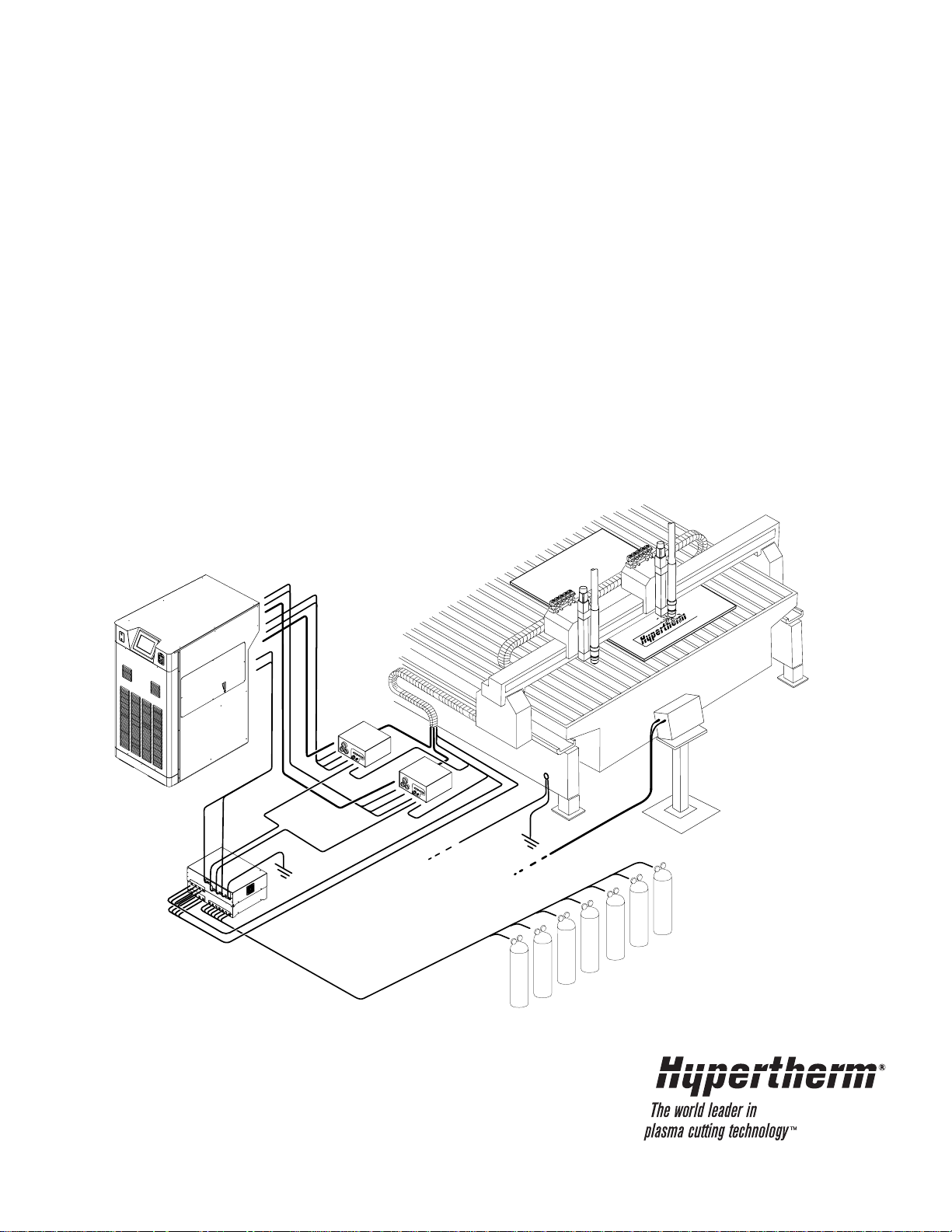
HD4070 Components, Cables and Hoses For 1-Torch Option Use with Order Form
D
Page 56

Distributor Information:
Customer Information:
Work Lead
9
123418 10 ft (3 m)
023136 20 ft (6.1 m)
023078 25 ft (7.6 m)
023101 30 ft (9.1 m)
023135 40 ft (12.2 m)
023079 50 ft (15.2 m)
023124 75 ft (23 m)
023080 100 ft (30.5 m)
023081 150 ft (45.7 m)
CNC Interface Cable Power Supply to CNC
12
123437 10 ft (3 m)
123438 20 ft (6.1 m)
123439 25 ft (7.6 m)
123440 30 ft (9.1 m)
123441 40 ft (12.2 m)
123442 50 ft (15.2 m)
123443 75 ft (23 m)
123444 100 ft (30.5 m)
123445 150 ft (45.7 m)
Power Cable Ignition Console to Off Valve
15
123451 6 ft (1.8 m)
123452 10 ft (3 m)
123453 15 ft (4.6 m)
Torch Assembly with Leads
16
128500 6 ft (1.8 m)
128501 10 ft (3 m)
128502 15 ft (4.6 m)
Quantity 1 Each
Gas Console
078085
Ignition Console
078088
Off Valve Assembly
129563
2
3
4
Coolant Hoses, Pilot Arc & Negative Leads
5
6
7 8
128412 10 ft (3 m)
128413 20 ft.(6.1 m)
128414 25 ft.(7.6 m)
128415 30 ft.(9.1 m)
128416 40 ft.(12.2 m)
128417 50 ft.(15.2 m)
128418 75 ft.(23 m)
128419 100 ft.(30.5 m)
128420 150 ft.(45.7 m)
Power Supply to Ignition Console Hose/Lead Package
Signal Cable & Power Cable
10
11
Power Supply to Gas Console Cable Package
128421 10 ft.(3 m)
128422 20 ft.(6.1 m)
128423 25 ft.(7.6 m)
128424 30 ft.(9.1 m)
128425 40 ft.(12.2 m)
128426 50 ft.(15.2 m)
128427 75 ft.(23 m)
128428 100 ft.(30.5 m)
128429 150 ft.(45.7 m)
Grounding Wires - Customer Supplied
Power Supply Cable - Customer Supplied
Gas Supply Hoses - Use form
17
18
19
Power Cable Gas Console to Ignition Console
14
123446 10 ft (3 m)
123447 20 ft (6.1 m)
123448 25 ft (7.6 m)
123449 30 ft (9.1 m)
123450 40 ft (12.2 m)
123512 50 ft (15.2 m)
123559 60 ft (18.3 m)
123513 75 ft (23 m)
123514 100 ft (30.5 m)
Gas Hoses Gas Console to Off-Valve
13
128445 15 ft (4.6 m)
128446 20 ft (6.1 m)
128447 25 ft (7.6 m)
128448 30 ft (9.1 m)
128449 35 ft (10.7 m)
128450 40 ft (12.2 m)
128451 45 ft (13.7 m)
128558 50 ft (15.2 m)
128559 60 ft (18.3 m)
128550 75 ft (23 m)
128551 100 ft (30.5 m)
HYPERTHERM - Order Form
HD4070 Components, Cables and Hoses
For 1-Torch Option
D
1
Power Supply
Use form or
BA
F
0
Page 57

Page 58

Distributor Information:
Customer Information:
Work Lead
9
123418 10 ft (3 m)
023136 20 ft (6.1 m)
023078 25 ft (7.6 m)
023101 30 ft (9.1 m)
023135 40 ft (12.2 m)
023079 50 ft (15.2 m)
023124 75 ft (23 m)
023080 100 ft (30.5 m)
023081 150 ft (45.7 m)
CNC Interface Cable Power Supply to CNC
12
123437 10 ft (3 m)
123438 20 ft (6.1 m)
123439 25 ft (7.6 m)
123440 30 ft (9.1 m)
123441 40 ft (12.2 m)
123442 50 ft (15.2 m)
123443 75 ft (23 m)
123444 100 ft (30.5 m)
123445 150 ft (45.7 m)
Power Cable Ignition Console to Off Valve
15
123451 6 ft (1.8 m)
123452 10 ft (3 m)
123453 15 ft (4.6 m)
Torch Assembly with Leads
16
128500 6 ft (1.8 m)
128501 10 ft (3 m)
128502 15 ft (4.6 m)
Quantity 1 Each
Gas Console
078085
Ignition Console
078088
Off Valve Assembly
129563
2
3
4
Coolant Hoses, Pilot Arc & Negative Leads
5
6
7 8
128412 10 ft (3 m)
128413 20 ft.(6.1 m)
128414 25 ft.(7.6 m)
128415 30 ft.(9.1 m)
128416 40 ft.(12.2 m)
128417 50 ft.(15.2 m)
128418 75 ft.(23 m)
128419 100 ft.(30.5 m)
128420 150 ft.(45.7 m)
Power Supply to Ignition Console Hose/Lead Package
Signal Cable & Power Cable
10
11
Power Supply to Gas Console Cable Package
128421 10 ft.(3 m)
128422 20 ft.(6.1 m)
128423 25 ft.(7.6 m)
128424 30 ft.(9.1 m)
128425 40 ft.(12.2 m)
128426 50 ft.(15.2 m)
128427 75 ft.(23 m)
128428 100 ft.(30.5 m)
128429 150 ft.(45.7 m)
Grounding Wires - Customer Supplied
Power Supply Cable - Customer Supplied
Gas Supply Hoses - Use form
17
18
19
Power Cable Gas Console to Ignition Console
14
123446 10 ft (3 m)
123447 20 ft (6.1 m)
123448 25 ft (7.6 m)
123449 30 ft (9.1 m)
123450 40 ft (12.2 m)
123512 50 ft (15.2 m)
123559 60 ft (18.3 m)
123513 75 ft (23 m)
123514 100 ft (30.5 m)
Gas Hoses Gas Console to Off-Valve
13
128445 15 ft (4.6 m)
128446 20 ft (6.1 m)
128447 25 ft (7.6 m)
128448 30 ft (9.1 m)
128449 35 ft (10.7 m)
128450 40 ft (12.2 m)
128451 45 ft (13.7 m)
128558 50 ft (15.2 m)
128559 60 ft (18.3 m)
128550 75 ft (23 m)
128551 100 ft (30.5 m)
HYPERTHERM - Order Form
HD4070 Components, Cables and Hoses
For 1-Torch Option
D
1
Power Supply
Use form or
BA
F
0
Page 59

Page 60

Distributor Information:
Customer Information:
Work Lead
9
123418 10 ft (3 m)
023136 20 ft (6.1 m)
023078 25 ft (7.6 m)
023101 30 ft (9.1 m)
023135 40 ft (12.2 m)
023079 50 ft (15.2 m)
023124 75 ft (23 m)
023080 100 ft (30.5 m)
023081 150 ft (45.7 m)
CNC Interface Cable Power Supply to CNC
12
123437 10 ft (3 m)
123438 20 ft (6.1 m)
123439 25 ft (7.6 m)
123440 30 ft (9.1 m)
123441 40 ft (12.2 m)
123442 50 ft (15.2 m)
123443 75 ft (23 m)
123444 100 ft (30.5 m)
123445 150 ft (45.7 m)
Power Cable Ignition Console to Off Valve
15
123451 6 ft (1.8 m)
123452 10 ft (3 m)
123453 15 ft (4.6 m)
Torch Assembly with Leads
16
128500 6 ft (1.8 m)
128501 10 ft (3 m)
128502 15 ft (4.6 m)
Quantity 1 Each
Gas Console
078085
Ignition Console
078088
Off Valve Assembly
129563
2
3
4
Coolant Hoses, Pilot Arc & Negative Leads
5
6
7 8
128412 10 ft (3 m)
128413 20 ft.(6.1 m)
128414 25 ft.(7.6 m)
128415 30 ft.(9.1 m)
128416 40 ft.(12.2 m)
128417 50 ft.(15.2 m)
128418 75 ft.(23 m)
128419 100 ft.(30.5 m)
128420 150 ft.(45.7 m)
Power Supply to Ignition Console Hose/Lead Package
Signal Cable & Power Cable
10
11
Power Supply to Gas Console Cable Package
128421 10 ft.(3 m)
128422 20 ft.(6.1 m)
128423 25 ft.(7.6 m)
128424 30 ft.(9.1 m)
128425 40 ft.(12.2 m)
128426 50 ft.(15.2 m)
128427 75 ft.(23 m)
128428 100 ft.(30.5 m)
128429 150 ft.(45.7 m)
Grounding Wires - Customer Supplied
Power Supply Cable - Customer Supplied
Gas Supply Hoses - Use form
17
18
19
Power Cable Gas Console to Ignition Console
14
123446 10 ft (3 m)
123447 20 ft (6.1 m)
123448 25 ft (7.6 m)
123449 30 ft (9.1 m)
123450 40 ft (12.2 m)
123512 50 ft (15.2 m)
123559 60 ft (18.3 m)
123513 75 ft (23 m)
123514 100 ft (30.5 m)
Gas Hoses Gas Console to Off-Valve
13
128445 15 ft (4.6 m)
128446 20 ft (6.1 m)
128447 25 ft (7.6 m)
128448 30 ft (9.1 m)
128449 35 ft (10.7 m)
128450 40 ft (12.2 m)
128451 45 ft (13.7 m)
128558 50 ft (15.2 m)
128559 60 ft (18.3 m)
128550 75 ft (23 m)
128551 100 ft (30.5 m)
HYPERTHERM - Order Form
HD4070 Components, Cables and Hoses
For 1-Torch Option
D
1
Power Supply
Use form or
BA
F
0
Page 61

Page 62

Distributor Information:
Customer Information:
Work Lead
9
123418 10 ft (3 m)
023136 20 ft (6.1 m)
023078 25 ft (7.6 m)
023101 30 ft (9.1 m)
023135 40 ft (12.2 m)
023079 50 ft (15.2 m)
023124 75 ft (23 m)
023080 100 ft (30.5 m)
023081 150 ft (45.7 m)
CNC Interface Cable Power Supply to CNC
12
123437 10 ft (3 m)
123438 20 ft (6.1 m)
123439 25 ft (7.6 m)
123440 30 ft (9.1 m)
123441 40 ft (12.2 m)
123442 50 ft (15.2 m)
123443 75 ft (23 m)
123444 100 ft (30.5 m)
123445 150 ft (45.7 m)
Power Cable Ignition Console to Off Valve
15
123451 6 ft (1.8 m)
123452 10 ft (3 m)
123453 15 ft (4.6 m)
Torch Assembly with Leads
16
128500 6 ft (1.8 m)
128501 10 ft (3 m)
128502 15 ft (4.6 m)
Quantity 1 Each
Gas Console
078085
Ignition Console
078088
Off Valve Assembly
129563
2
3
4
Coolant Hoses, Pilot Arc & Negative Leads
5
6
7 8
128412 10 ft (3 m)
128413 20 ft.(6.1 m)
128414 25 ft.(7.6 m)
128415 30 ft.(9.1 m)
128416 40 ft.(12.2 m)
128417 50 ft.(15.2 m)
128418 75 ft.(23 m)
128419 100 ft.(30.5 m)
128420 150 ft.(45.7 m)
Power Supply to Ignition Console Hose/Lead Package
Signal Cable & Power Cable
10
11
Power Supply to Gas Console Cable Package
128421 10 ft.(3 m)
128422 20 ft.(6.1 m)
128423 25 ft.(7.6 m)
128424 30 ft.(9.1 m)
128425 40 ft.(12.2 m)
128426 50 ft.(15.2 m)
128427 75 ft.(23 m)
128428 100 ft.(30.5 m)
128429 150 ft.(45.7 m)
Grounding Wires - Customer Supplied
Power Supply Cable - Customer Supplied
Gas Supply Hoses - Use form
17
18
19
Power Cable Gas Console to Ignition Console
14
123446 10 ft (3 m)
123447 20 ft (6.1 m)
123448 25 ft (7.6 m)
123449 30 ft (9.1 m)
123450 40 ft (12.2 m)
123512 50 ft (15.2 m)
123559 60 ft (18.3 m)
123513 75 ft (23 m)
123514 100 ft (30.5 m)
Gas Hoses Gas Console to Off-Valve
13
128445 15 ft (4.6 m)
128446 20 ft (6.1 m)
128447 25 ft (7.6 m)
128448 30 ft (9.1 m)
128449 35 ft (10.7 m)
128450 40 ft (12.2 m)
128451 45 ft (13.7 m)
128558 50 ft (15.2 m)
128559 60 ft (18.3 m)
128550 75 ft (23 m)
128551 100 ft (30.5 m)
HYPERTHERM - Order Form
HD4070 Components, Cables and Hoses
For 1-Torch Option
D
1
Power Supply
Use form or
BA
F
0
Page 63

Page 64

Distributor Information:
Customer Information:
Work Lead
9
123418 10 ft (3 m)
023136 20 ft (6.1 m)
023078 25 ft (7.6 m)
023101 30 ft (9.1 m)
023135 40 ft (12.2 m)
023079 50 ft (15.2 m)
023124 75 ft (23 m)
023080 100 ft (30.5 m)
023081 150 ft (45.7 m)
CNC Interface Cable Power Supply to CNC
12
123437 10 ft (3 m)
123438 20 ft (6.1 m)
123439 25 ft (7.6 m)
123440 30 ft (9.1 m)
123441 40 ft (12.2 m)
123442 50 ft (15.2 m)
123443 75 ft (23 m)
123444 100 ft (30.5 m)
123445 150 ft (45.7 m)
Power Cable Ignition Console to Off Valve
15
123451 6 ft (1.8 m)
123452 10 ft (3 m)
123453 15 ft (4.6 m)
Torch Assembly with Leads
16
128500 6 ft (1.8 m)
128501 10 ft (3 m)
128502 15 ft (4.6 m)
Quantity 1 Each
Gas Console
078085
Ignition Console
078088
Off Valve Assembly
129563
2
3
4
Coolant Hoses, Pilot Arc & Negative Leads
5
6
7 8
128412 10 ft (3 m)
128413 20 ft.(6.1 m)
128414 25 ft.(7.6 m)
128415 30 ft.(9.1 m)
128416 40 ft.(12.2 m)
128417 50 ft.(15.2 m)
128418 75 ft.(23 m)
128419 100 ft.(30.5 m)
128420 150 ft.(45.7 m)
Power Supply to Ignition Console Hose/Lead Package
Signal Cable & Power Cable
10
11
Power Supply to Gas Console Cable Package
128421 10 ft.(3 m)
128422 20 ft.(6.1 m)
128423 25 ft.(7.6 m)
128424 30 ft.(9.1 m)
128425 40 ft.(12.2 m)
128426 50 ft.(15.2 m)
128427 75 ft.(23 m)
128428 100 ft.(30.5 m)
128429 150 ft.(45.7 m)
Grounding Wires - Customer Supplied
Power Supply Cable - Customer Supplied
Gas Supply Hoses - Use form
17
18
19
Power Cable Gas Console to Ignition Console
14
123446 10 ft (3 m)
123447 20 ft (6.1 m)
123448 25 ft (7.6 m)
123449 30 ft (9.1 m)
123450 40 ft (12.2 m)
123512 50 ft (15.2 m)
123559 60 ft (18.3 m)
123513 75 ft (23 m)
123514 100 ft (30.5 m)
Gas Hoses Gas Console to Off-Valve
13
128445 15 ft (4.6 m)
128446 20 ft (6.1 m)
128447 25 ft (7.6 m)
128448 30 ft (9.1 m)
128449 35 ft (10.7 m)
128450 40 ft (12.2 m)
128451 45 ft (13.7 m)
128558 50 ft (15.2 m)
128559 60 ft (18.3 m)
128550 75 ft (23 m)
128551 100 ft (30.5 m)
HYPERTHERM - Order Form
HD4070 Components, Cables and Hoses
For 1-Torch Option
D
1
Power Supply
Use form or
BA
F
0
Page 65

Page 66

Page 67

18
Bold lines show second torch cables, hoses and components
7
8
5
6
1
15
16
17
14
13
17
2
3
4
4070.98A
4
3
17
17
17
10
11
9
12
19
16
16 a
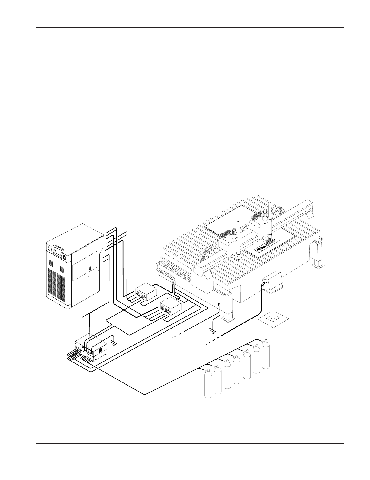
HD4070 Components, Cables and Hoses For 2-Torch Option Use with Order Form
E
Page 68
Distributor Information:
Customer Information:
Quantity: As Marked
Gas Console - Quantity 1
078085
Ignition Console - Quantity 2
078088
Off Valve Assembly - Quantity 2
129563
2
3
4
CNC Interface Cable - Quantity 1
Power Supply to CNC
12
123437 10 ft (3 m)
123438 20 ft (6.1 m)
123439 25 ft (7.6 m)
123440 30 ft (9.1 m)
123441 40 ft (12.2 m)
123442 50 ft (15.2 m)
123443 75 ft (23 m)
123444 100 ft (30.5 m)
123445 150 ft (45.7 m)
Work Lead - Quantity 1
9
123418 10 ft (3 m)
023136 20 ft (6.1 m)
023078 25 ft (7.6 m)
023101 30 ft (9.1 m)
023135 40 ft (12.2 m)
023079 50 ft (15.2 m)
023124 75 ft (23 m)
023080 100 ft (30.5 m)
023081 150 ft (45.7 m)
Torch Assembly with Leads - Quantity 2
16
128500 6 ft (1.8 m)
128501 10 ft (3 m)
128502 15 ft (4.6 m)
Power Cable - Quantity 2
Ignition Console to Off Valve
15
123451 6 ft (1.8 m)
123452 10 ft (3 m)
123453 15 ft (4.6 m)
Coolant Hoses, Pilot Arc & Negative Leads
5
6
7 8
128412 10 ft (3 m)
128413 20 ft.(6.1 m)
128414 25 ft.(7.6 m)
128415 30 ft.(9.1 m)
128416 40 ft.(12.2 m)
128417 50 ft.(15.2 m)
128418 75 ft.(23 m)
128419 100 ft.(30.5 m)
128420 150 ft.(45.7 m)
Power Supply to Ignition Console
Hose/Lead Package - Quantity 2
Signal Cable & Power Cable
10
11
Power Supply to Gas Console
Cable Package - Quantity 1
128421 10 ft.(3 m)
128422 20 ft.(6.1 m)
128423 25 ft.(7.6 m)
128424 30 ft.(9.1 m)
128425 40 ft.(12.2 m)
128426 50 ft.(15.2 m)
128427 75 ft.(23 m)
128428 100 ft.(30.5 m)
128429 150 ft.(45.7 m)
1
Power Supply
Use form or
Power Cable - Quantity 2
Gas Console to Ignition Console
14
123446 10 ft (3 m)
123447 20 ft (6.1 m)
123448 25 ft (7.6 m)
123449 30 ft (9.1 m)
123450 40 ft (12.2 m)
123512 50 ft (15.2 m)
123559 60 ft (18.3 m)
123513 75 ft (23 m)
123514 100 ft (30.5 m)
16 a
Torch Receptacle Plug - Quantity
1
129671
Gas Hoses - Quantity 2
Gas Console to Off-Valve
13
128445 15 ft (4.6 m)
128446 20 ft (6.1 m)
128447 25 ft (7.6 m)
128448 30 ft (9.1 m)
128449 35 ft (10.7 m)
128450 40 ft (12.2 m)
128451 45 ft (13.7 m)
128558 50 ft (15.2 m)
128559 60 ft (18.3 m)
128550 75 ft (23 m)
128551 100 ft (30.5 m)
Grounding Wires - Customer Supplied
Power Supply Cable - Customer Supplied
Gas Supply Hoses - Use form
17
18
19
F
A C
HYPERTHERM - Order Form
HD4070 Components, Cables and Hoses
For 2-Torch Option
E
Note: A torch receptacle plug must be used if a
two torch system is being used in single torch
mode. See form E
0
Page 69

Page 70

Distributor Information:
Customer Information:
Quantity: As Marked
Gas Console - Quantity 1
078085
Ignition Console - Quantity 2
078088
Off Valve Assembly - Quantity 2
129563
2
3
4
CNC Interface Cable - Quantity 1
Power Supply to CNC
12
123437 10 ft (3 m)
123438 20 ft (6.1 m)
123439 25 ft (7.6 m)
123440 30 ft (9.1 m)
123441 40 ft (12.2 m)
123442 50 ft (15.2 m)
123443 75 ft (23 m)
123444 100 ft (30.5 m)
123445 150 ft (45.7 m)
Work Lead - Quantity 1
9
123418 10 ft (3 m)
023136 20 ft (6.1 m)
023078 25 ft (7.6 m)
023101 30 ft (9.1 m)
023135 40 ft (12.2 m)
023079 50 ft (15.2 m)
023124 75 ft (23 m)
023080 100 ft (30.5 m)
023081 150 ft (45.7 m)
Torch Assembly with Leads - Quantity 2
16
128500 6 ft (1.8 m)
128501 10 ft (3 m)
128502 15 ft (4.6 m)
Power Cable - Quantity 2
Ignition Console to Off Valve
15
123451 6 ft (1.8 m)
123452 10 ft (3 m)
123453 15 ft (4.6 m)
Coolant Hoses, Pilot Arc & Negative Leads
5
6
7 8
128412 10 ft (3 m)
128413 20 ft.(6.1 m)
128414 25 ft.(7.6 m)
128415 30 ft.(9.1 m)
128416 40 ft.(12.2 m)
128417 50 ft.(15.2 m)
128418 75 ft.(23 m)
128419 100 ft.(30.5 m)
128420 150 ft.(45.7 m)
Power Supply to Ignition Console
Hose/Lead Package - Quantity 2
Signal Cable & Power Cable
10
11
Power Supply to Gas Console
Cable Package - Quantity 1
128421 10 ft.(3 m)
128422 20 ft.(6.1 m)
128423 25 ft.(7.6 m)
128424 30 ft.(9.1 m)
128425 40 ft.(12.2 m)
128426 50 ft.(15.2 m)
128427 75 ft.(23 m)
128428 100 ft.(30.5 m)
128429 150 ft.(45.7 m)
1
Power Supply
Use form or
Power Cable - Quantity 2
Gas Console to Ignition Console
14
123446 10 ft (3 m)
123447 20 ft (6.1 m)
123448 25 ft (7.6 m)
123449 30 ft (9.1 m)
123450 40 ft (12.2 m)
123512 50 ft (15.2 m)
123559 60 ft (18.3 m)
123513 75 ft (23 m)
123514 100 ft (30.5 m)
16 a
Torch Receptacle Plug - Quantity
1
129671
Gas Hoses - Quantity 2
Gas Console to Off-Valve
13
128445 15 ft (4.6 m)
128446 20 ft (6.1 m)
128447 25 ft (7.6 m)
128448 30 ft (9.1 m)
128449 35 ft (10.7 m)
128450 40 ft (12.2 m)
128451 45 ft (13.7 m)
128558 50 ft (15.2 m)
128559 60 ft (18.3 m)
128550 75 ft (23 m)
128551 100 ft (30.5 m)
Grounding Wires - Customer Supplied
Power Supply Cable - Customer Supplied
Gas Supply Hoses - Use form
17
18
19
F
A C
HYPERTHERM - Order Form
HD4070 Components, Cables and Hoses
For 2-Torch Option
E
Note: A torch receptacle plug must be used if a
two torch system is being used in single torch
mode. See form E
0
Page 71

Page 72

Distributor Information:
Customer Information:
Quantity: As Marked
Gas Console - Quantity 1
078085
Ignition Console - Quantity 2
078088
Off Valve Assembly - Quantity 2
129563
2
3
4
CNC Interface Cable - Quantity 1
Power Supply to CNC
12
123437 10 ft (3 m)
123438 20 ft (6.1 m)
123439 25 ft (7.6 m)
123440 30 ft (9.1 m)
123441 40 ft (12.2 m)
123442 50 ft (15.2 m)
123443 75 ft (23 m)
123444 100 ft (30.5 m)
123445 150 ft (45.7 m)
Work Lead - Quantity 1
9
123418 10 ft (3 m)
023136 20 ft (6.1 m)
023078 25 ft (7.6 m)
023101 30 ft (9.1 m)
023135 40 ft (12.2 m)
023079 50 ft (15.2 m)
023124 75 ft (23 m)
023080 100 ft (30.5 m)
023081 150 ft (45.7 m)
Torch Assembly with Leads - Quantity 2
16
128500 6 ft (1.8 m)
128501 10 ft (3 m)
128502 15 ft (4.6 m)
Power Cable - Quantity 2
Ignition Console to Off Valve
15
123451 6 ft (1.8 m)
123452 10 ft (3 m)
123453 15 ft (4.6 m)
Coolant Hoses, Pilot Arc & Negative Leads
5
6
7 8
128412 10 ft (3 m)
128413 20 ft.(6.1 m)
128414 25 ft.(7.6 m)
128415 30 ft.(9.1 m)
128416 40 ft.(12.2 m)
128417 50 ft.(15.2 m)
128418 75 ft.(23 m)
128419 100 ft.(30.5 m)
128420 150 ft.(45.7 m)
Power Supply to Ignition Console
Hose/Lead Package - Quantity 2
Signal Cable & Power Cable
10
11
Power Supply to Gas Console
Cable Package - Quantity 1
128421 10 ft.(3 m)
128422 20 ft.(6.1 m)
128423 25 ft.(7.6 m)
128424 30 ft.(9.1 m)
128425 40 ft.(12.2 m)
128426 50 ft.(15.2 m)
128427 75 ft.(23 m)
128428 100 ft.(30.5 m)
128429 150 ft.(45.7 m)
1
Power Supply
Use form or
Power Cable - Quantity 2
Gas Console to Ignition Console
14
123446 10 ft (3 m)
123447 20 ft (6.1 m)
123448 25 ft (7.6 m)
123449 30 ft (9.1 m)
123450 40 ft (12.2 m)
123512 50 ft (15.2 m)
123559 60 ft (18.3 m)
123513 75 ft (23 m)
123514 100 ft (30.5 m)
16 a
Torch Receptacle Plug - Quantity
1
129671
Gas Hoses - Quantity 2
Gas Console to Off-Valve
13
128445 15 ft (4.6 m)
128446 20 ft (6.1 m)
128447 25 ft (7.6 m)
128448 30 ft (9.1 m)
128449 35 ft (10.7 m)
128450 40 ft (12.2 m)
128451 45 ft (13.7 m)
128558 50 ft (15.2 m)
128559 60 ft (18.3 m)
128550 75 ft (23 m)
128551 100 ft (30.5 m)
Grounding Wires - Customer Supplied
Power Supply Cable - Customer Supplied
Gas Supply Hoses - Use form
17
18
19
F
A C
HYPERTHERM - Order Form
HD4070 Components, Cables and Hoses
For 2-Torch Option
E
Note: A torch receptacle plug must be used if a
two torch system is being used in single torch
mode. See form E
0
Page 73

Page 74

Distributor Information:
Customer Information:
Quantity: As Marked
Gas Console - Quantity 1
078085
Ignition Console - Quantity 2
078088
Off Valve Assembly - Quantity 2
129563
2
3
4
CNC Interface Cable - Quantity 1
Power Supply to CNC
12
123437 10 ft (3 m)
123438 20 ft (6.1 m)
123439 25 ft (7.6 m)
123440 30 ft (9.1 m)
123441 40 ft (12.2 m)
123442 50 ft (15.2 m)
123443 75 ft (23 m)
123444 100 ft (30.5 m)
123445 150 ft (45.7 m)
Work Lead - Quantity 1
9
123418 10 ft (3 m)
023136 20 ft (6.1 m)
023078 25 ft (7.6 m)
023101 30 ft (9.1 m)
023135 40 ft (12.2 m)
023079 50 ft (15.2 m)
023124 75 ft (23 m)
023080 100 ft (30.5 m)
023081 150 ft (45.7 m)
Torch Assembly with Leads - Quantity 2
16
128500 6 ft (1.8 m)
128501 10 ft (3 m)
128502 15 ft (4.6 m)
Power Cable - Quantity 2
Ignition Console to Off Valve
15
123451 6 ft (1.8 m)
123452 10 ft (3 m)
123453 15 ft (4.6 m)
Coolant Hoses, Pilot Arc & Negative Leads
5
6
7 8
128412 10 ft (3 m)
128413 20 ft.(6.1 m)
128414 25 ft.(7.6 m)
128415 30 ft.(9.1 m)
128416 40 ft.(12.2 m)
128417 50 ft.(15.2 m)
128418 75 ft.(23 m)
128419 100 ft.(30.5 m)
128420 150 ft.(45.7 m)
Power Supply to Ignition Console
Hose/Lead Package - Quantity 2
Signal Cable & Power Cable
10
11
Power Supply to Gas Console
Cable Package - Quantity 1
128421 10 ft.(3 m)
128422 20 ft.(6.1 m)
128423 25 ft.(7.6 m)
128424 30 ft.(9.1 m)
128425 40 ft.(12.2 m)
128426 50 ft.(15.2 m)
128427 75 ft.(23 m)
128428 100 ft.(30.5 m)
128429 150 ft.(45.7 m)
1
Power Supply
Use form or
Power Cable - Quantity 2
Gas Console to Ignition Console
14
123446 10 ft (3 m)
123447 20 ft (6.1 m)
123448 25 ft (7.6 m)
123449 30 ft (9.1 m)
123450 40 ft (12.2 m)
123512 50 ft (15.2 m)
123559 60 ft (18.3 m)
123513 75 ft (23 m)
123514 100 ft (30.5 m)
16 a
Torch Receptacle Plug - Quantity
1
129671
Gas Hoses - Quantity 2
Gas Console to Off-Valve
13
128445 15 ft (4.6 m)
128446 20 ft (6.1 m)
128447 25 ft (7.6 m)
128448 30 ft (9.1 m)
128449 35 ft (10.7 m)
128450 40 ft (12.2 m)
128451 45 ft (13.7 m)
128558 50 ft (15.2 m)
128559 60 ft (18.3 m)
128550 75 ft (23 m)
128551 100 ft (30.5 m)
Grounding Wires - Customer Supplied
Power Supply Cable - Customer Supplied
Gas Supply Hoses - Use form
17
18
19
F
A C
HYPERTHERM - Order Form
HD4070 Components, Cables and Hoses
For 2-Torch Option
E
Note: A torch receptacle plug must be used if a
two torch system is being used in single torch
mode. See form E
0
Page 75

Page 76

Distributor Information:
Customer Information:
Quantity: As Marked
Gas Console - Quantity 1
078085
Ignition Console - Quantity 2
078088
Off Valve Assembly - Quantity 2
129563
2
3
4
CNC Interface Cable - Quantity 1
Power Supply to CNC
12
123437 10 ft (3 m)
123438 20 ft (6.1 m)
123439 25 ft (7.6 m)
123440 30 ft (9.1 m)
123441 40 ft (12.2 m)
123442 50 ft (15.2 m)
123443 75 ft (23 m)
123444 100 ft (30.5 m)
123445 150 ft (45.7 m)
Work Lead - Quantity 1
9
123418 10 ft (3 m)
023136 20 ft (6.1 m)
023078 25 ft (7.6 m)
023101 30 ft (9.1 m)
023135 40 ft (12.2 m)
023079 50 ft (15.2 m)
023124 75 ft (23 m)
023080 100 ft (30.5 m)
023081 150 ft (45.7 m)
Torch Assembly with Leads - Quantity 2
16
128500 6 ft (1.8 m)
128501 10 ft (3 m)
128502 15 ft (4.6 m)
Power Cable - Quantity 2
Ignition Console to Off Valve
15
123451 6 ft (1.8 m)
123452 10 ft (3 m)
123453 15 ft (4.6 m)
Coolant Hoses, Pilot Arc & Negative Leads
5
6
7 8
128412 10 ft (3 m)
128413 20 ft.(6.1 m)
128414 25 ft.(7.6 m)
128415 30 ft.(9.1 m)
128416 40 ft.(12.2 m)
128417 50 ft.(15.2 m)
128418 75 ft.(23 m)
128419 100 ft.(30.5 m)
128420 150 ft.(45.7 m)
Power Supply to Ignition Console
Hose/Lead Package - Quantity 2
Signal Cable & Power Cable
10
11
Power Supply to Gas Console
Cable Package - Quantity 1
128421 10 ft.(3 m)
128422 20 ft.(6.1 m)
128423 25 ft.(7.6 m)
128424 30 ft.(9.1 m)
128425 40 ft.(12.2 m)
128426 50 ft.(15.2 m)
128427 75 ft.(23 m)
128428 100 ft.(30.5 m)
128429 150 ft.(45.7 m)
1
Power Supply
Use form or
Power Cable - Quantity 2
Gas Console to Ignition Console
14
123446 10 ft (3 m)
123447 20 ft (6.1 m)
123448 25 ft (7.6 m)
123449 30 ft (9.1 m)
123450 40 ft (12.2 m)
123512 50 ft (15.2 m)
123559 60 ft (18.3 m)
123513 75 ft (23 m)
123514 100 ft (30.5 m)
16 a
Torch Receptacle Plug - Quantity
1
129671
Gas Hoses - Quantity 2
Gas Console to Off-Valve
13
128445 15 ft (4.6 m)
128446 20 ft (6.1 m)
128447 25 ft (7.6 m)
128448 30 ft (9.1 m)
128449 35 ft (10.7 m)
128450 40 ft (12.2 m)
128451 45 ft (13.7 m)
128558 50 ft (15.2 m)
128559 60 ft (18.3 m)
128550 75 ft (23 m)
128551 100 ft (30.5 m)
Grounding Wires - Customer Supplied
Power Supply Cable - Customer Supplied
Gas Supply Hoses - Use form
17
18
19
F
A C
HYPERTHERM - Order Form
HD4070 Components, Cables and Hoses
For 2-Torch Option
E
Note: A torch receptacle plug must be used if a
two torch system is being used in single torch
mode. See form E
0
Page 77

Page 78

Page 79

Page 80

Customer Information:
Distributor Information:
Remote Display Cable Kits - For removal of
preinstalled display and installation at a remote location.
128535 10 ft.(3 m)
128536 20 ft.(6.1 m)
128537 25 ft.(7.6 m)
128538 30 ft.(9 m)
128539 40 ft.(12 m)
128540 50 ft.(15 m)
128541 75 ft.(23 m)
128542 100 ft.(30.5 m)
128543 150 ft.(46 m)
HYPERTHERM - HD4070 Upgrades and Optional Components Order Form
F
THC Upgrade Kits - For use with a system that
does not have a preinstalled THC
128523 THC #1
128524 THC #2
Note: If ordering two THC systems
please check both boxes.
Use form to order components Through For one THC upgrade
20
25
Use form to order components Through For two THC upgrade
20
25
C
B
for Nitrogen - 3/8" Black RH "B"
024203 15 ft.(4.6 m)
024134 25 ft.(7.6 m)
024112 50 ft.(15.2 m)
024148 75 ft.(23 m)
for Hydrogen (H5,H35 or Methane) - 3/8" Red LH "B"
024655 15 ft.(4.6 m)
024384 25 ft.(7.6 m)
024656 50 ft.(15.2 m)
024657 75 ft.(23 m)
for Air - 3/8" Black #6
024658 15 ft.(4.6 m)
024659 25 ft.(7.6 m)
024660 50 ft.(15.2 m)
024661 75 ft.(23 m)
128545 - 2-Stage Nitrogen
128546 - 2-Stage Hydrogen (H5,H35 and Methane)
128547 - 2-Stage Air
128548 - 1-Stage (for use with cryogenic liquid Nitrogen or Oxygen)
Gas Regulator Kits
128544 - 2-Stage Oxygen
Gas Hose Assemblies
for Oxygen - 3/8" Blue RH "B"
024204 15 ft.(4.6 m)
024205 25 ft.(7.6 m)
024155 50 ft.(15.2 m)
024398 75 ft.(23 m)
19
26
27
When configuring the gas console to the supply gases, make sure that all
hoses, hose connections and fittings are acceptable for use with oxygen,
argon-hydrogen and methane. Installation must be made in accordance
with local and national codes.
0
Page 81

Page 82

Customer Information:
Distributor Information:
Remote Display Cable Kits - For removal of
preinstalled display and installation at a remote location.
128535 10 ft.(3 m)
128536 20 ft.(6.1 m)
128537 25 ft.(7.6 m)
128538 30 ft.(9 m)
128539 40 ft.(12 m)
128540 50 ft.(15 m)
128541 75 ft.(23 m)
128542 100 ft.(30.5 m)
128543 150 ft.(46 m)
HYPERTHERM - HD4070 Upgrades and Optional Components Order Form
F
THC Upgrade Kits - For use with a system that
does not have a preinstalled THC
128523 THC #1
128524 THC #2
Note: If ordering two THC systems
please check both boxes.
Use form to order components Through For one THC upgrade
20
25
Use form to order components Through For two THC upgrade
20
25
C
B
for Nitrogen - 3/8" Black RH "B"
024203 15 ft.(4.6 m)
024134 25 ft.(7.6 m)
024112 50 ft.(15.2 m)
024148 75 ft.(23 m)
for Hydrogen (H5,H35 or Methane) - 3/8" Red LH "B"
024655 15 ft.(4.6 m)
024384 25 ft.(7.6 m)
024656 50 ft.(15.2 m)
024657 75 ft.(23 m)
for Air - 3/8" Black #6
024658 15 ft.(4.6 m)
024659 25 ft.(7.6 m)
024660 50 ft.(15.2 m)
024661 75 ft.(23 m)
128545 - 2-Stage Nitrogen
128546 - 2-Stage Hydrogen (H5,H35 and Methane)
128547 - 2-Stage Air
128548 - 1-Stage (for use with cryogenic liquid Nitrogen or Oxygen)
Gas Regulator Kits
128544 - 2-Stage Oxygen
Gas Hose Assemblies
for Oxygen - 3/8" Blue RH "B"
024204 15 ft.(4.6 m)
024205 25 ft.(7.6 m)
024155 50 ft.(15.2 m)
024398 75 ft.(23 m)
19
26
27
When configuring the gas console to the supply gases, make sure that all
hoses, hose connections and fittings are acceptable for use with oxygen,
argon-hydrogen and methane. Installation must be made in accordance
with local and national codes.
0
Page 83

Page 84

Customer Information:
Distributor Information:
Remote Display Cable Kits - For removal of
preinstalled display and installation at a remote location.
128535 10 ft.(3 m)
128536 20 ft.(6.1 m)
128537 25 ft.(7.6 m)
128538 30 ft.(9 m)
128539 40 ft.(12 m)
128540 50 ft.(15 m)
128541 75 ft.(23 m)
128542 100 ft.(30.5 m)
128543 150 ft.(46 m)
HYPERTHERM - HD4070 Upgrades and Optional Components Order Form
F
THC Upgrade Kits - For use with a system that
does not have a preinstalled THC
128523 THC #1
128524 THC #2
Note: If ordering two THC systems
please check both boxes.
Use form to order components Through For one THC upgrade
20
25
Use form to order components Through For two THC upgrade
20
25
C
B
for Nitrogen - 3/8" Black RH "B"
024203 15 ft.(4.6 m)
024134 25 ft.(7.6 m)
024112 50 ft.(15.2 m)
024148 75 ft.(23 m)
for Hydrogen (H5,H35 or Methane) - 3/8" Red LH "B"
024655 15 ft.(4.6 m)
024384 25 ft.(7.6 m)
024656 50 ft.(15.2 m)
024657 75 ft.(23 m)
for Air - 3/8" Black #6
024658 15 ft.(4.6 m)
024659 25 ft.(7.6 m)
024660 50 ft.(15.2 m)
024661 75 ft.(23 m)
128545 - 2-Stage Nitrogen
128546 - 2-Stage Hydrogen (H5,H35 and Methane)
128547 - 2-Stage Air
128548 - 1-Stage (for use with cryogenic liquid Nitrogen or Oxygen)
Gas Regulator Kits
128544 - 2-Stage Oxygen
Gas Hose Assemblies
for Oxygen - 3/8" Blue RH "B"
024204 15 ft.(4.6 m)
024205 25 ft.(7.6 m)
024155 50 ft.(15.2 m)
024398 75 ft.(23 m)
19
26
27
When configuring the gas console to the supply gases, make sure that all
hoses, hose connections and fittings are acceptable for use with oxygen,
argon-hydrogen and methane. Installation must be made in accordance
with local and national codes.
0
Page 85

Page 86

Customer Information:
Distributor Information:
Remote Display Cable Kits - For removal of
preinstalled display and installation at a remote location.
128535 10 ft.(3 m)
128536 20 ft.(6.1 m)
128537 25 ft.(7.6 m)
128538 30 ft.(9 m)
128539 40 ft.(12 m)
128540 50 ft.(15 m)
128541 75 ft.(23 m)
128542 100 ft.(30.5 m)
128543 150 ft.(46 m)
HYPERTHERM - HD4070 Upgrades and Optional Components Order Form
F
THC Upgrade Kits - For use with a system that
does not have a preinstalled THC
128523 THC #1
128524 THC #2
Note: If ordering two THC systems
please check both boxes.
Use form to order components Through For one THC upgrade
20
25
Use form to order components Through For two THC upgrade
20
25
C
B
for Nitrogen - 3/8" Black RH "B"
024203 15 ft.(4.6 m)
024134 25 ft.(7.6 m)
024112 50 ft.(15.2 m)
024148 75 ft.(23 m)
for Hydrogen (H5,H35 or Methane) - 3/8" Red LH "B"
024655 15 ft.(4.6 m)
024384 25 ft.(7.6 m)
024656 50 ft.(15.2 m)
024657 75 ft.(23 m)
for Air - 3/8" Black #6
024658 15 ft.(4.6 m)
024659 25 ft.(7.6 m)
024660 50 ft.(15.2 m)
024661 75 ft.(23 m)
128545 - 2-Stage Nitrogen
128546 - 2-Stage Hydrogen (H5,H35 and Methane)
128547 - 2-Stage Air
128548 - 1-Stage (for use with cryogenic liquid Nitrogen or Oxygen)
Gas Regulator Kits
128544 - 2-Stage Oxygen
Gas Hose Assemblies
for Oxygen - 3/8" Blue RH "B"
024204 15 ft.(4.6 m)
024205 25 ft.(7.6 m)
024155 50 ft.(15.2 m)
024398 75 ft.(23 m)
19
26
27
When configuring the gas console to the supply gases, make sure that all
hoses, hose connections and fittings are acceptable for use with oxygen,
argon-hydrogen and methane. Installation must be made in accordance
with local and national codes.
0
Page 87

Page 88

Customer Information:
Distributor Information:
Remote Display Cable Kits - For removal of
preinstalled display and installation at a remote location.
128535 10 ft.(3 m)
128536 20 ft.(6.1 m)
128537 25 ft.(7.6 m)
128538 30 ft.(9 m)
128539 40 ft.(12 m)
128540 50 ft.(15 m)
128541 75 ft.(23 m)
128542 100 ft.(30.5 m)
128543 150 ft.(46 m)
HYPERTHERM - HD4070 Upgrades and Optional Components Order Form
F
THC Upgrade Kits - For use with a system that
does not have a preinstalled THC
128523 THC #1
128524 THC #2
Note: If ordering two THC systems
please check both boxes.
Use form to order components Through For one THC upgrade
20
25
Use form to order components Through For two THC upgrade
20
25
C
B
for Nitrogen - 3/8" Black RH "B"
024203 15 ft.(4.6 m)
024134 25 ft.(7.6 m)
024112 50 ft.(15.2 m)
024148 75 ft.(23 m)
for Hydrogen (H5,H35 or Methane) - 3/8" Red LH "B"
024655 15 ft.(4.6 m)
024384 25 ft.(7.6 m)
024656 50 ft.(15.2 m)
024657 75 ft.(23 m)
for Air - 3/8" Black #6
024658 15 ft.(4.6 m)
024659 25 ft.(7.6 m)
024660 50 ft.(15.2 m)
024661 75 ft.(23 m)
128545 - 2-Stage Nitrogen
128546 - 2-Stage Hydrogen (H5,H35 and Methane)
128547 - 2-Stage Air
128548 - 1-Stage (for use with cryogenic liquid Nitrogen or Oxygen)
Gas Regulator Kits
128544 - 2-Stage Oxygen
Gas Hose Assemblies
for Oxygen - 3/8" Blue RH "B"
024204 15 ft.(4.6 m)
024205 25 ft.(7.6 m)
024155 50 ft.(15.2 m)
024398 75 ft.(23 m)
19
26
27
When configuring the gas console to the supply gases, make sure that all
hoses, hose connections and fittings are acceptable for use with oxygen,
argon-hydrogen and methane. Installation must be made in accordance
with local and national codes.
0
 Loading...