


Echion™
Operator Manual
810770 – REVISION 3
ENGLISH

HyPrecision, Echion, and Hypertherm are trademarks of Hypertherm, Inc. and may be registered in the United States and other
countries. All other trademarks are the property of their respective holders.
Environmental stewardship is one of Hypertherm’s core values, and it is critical to our success and our customers’ success. We
are striving to reduce the environmental impact of everything we do. For more information:www.hypertherm.com/environment.
© 2020 Hypertherm, Inc.

Echion
Operator Manual
810770
REVISION 3
ENGLISH
Original instructions
June 2020
Hypertherm, Inc.
Hanover, NH 03755 USA
www.hypertherm.com

Hypertherm Europe B.V.
Vaartveld 9, 4704 SE
Roosendaal, Nederland
31 165 596907 Tel
31 165 596901 Fax
31 165 596908 Tel (Marketing)
31 (0) 165 596900 Tel (Technical Service)
00 800 4973 7843 Tel (Technical Service)
technicalservice.emea@hypertherm.com
(Technical Service Email)
Hypertherm (Shanghai) Trading Co., Ltd.
B301, 495 ShangZhong Road
Shanghai, 200231
PR China
86-21-80231122 Tel
86-21-80231120 Fax
86-21-80231128 Tel (Technical Service)
techsupport.china@hypertherm.com
(Technical Service Email)
South America & Central America: Hypertherm Brasil Ltda.
Rua Bras Cubas, 231 – Jardim Maia
Guarulhos, SP – Brasil
CEP 07115-030
55 11 2409 2636 Tel
tecnico.sa@hypertherm.com (Technical Service Email)
Hypertherm Korea Branch
#3904. APEC-ro 17. Heaundae-gu. Busan.
Korea 48060
82 (0)51 747 0358 Tel
82 (0)51 701 0358 Fax
Marketing.korea@hypertherm.com (Marketing Email)
TechSupportAPAC@hypertherm.com
(Technical Service Email)
Hypertherm Pty Limited
GPO Box 4836
Sydney NSW 2001, Australia
61 (0) 437 606 995 Tel
61 7 3219 9010 Fax
au.sales@Hypertherm.com (Main Office Email)
TechSupportAPAC@hypertherm.com
(Technical Service Email)
Hypertherm (India) Thermal Cutting Pvt. Ltd
A-18 / B-1 Extension,
Mohan Co-Operative Industrial Estate,
Mathura Road, New Delhi 110044, India
91-11-40521201/ 2/ 3 Tel
91-11 40521204 Fax
HTIndia.info@hypertherm.com (Main Office Email)
TechSupportAPAC@hypertherm.com
(Technical Service Email)
Hypertherm, Inc.
Etna Road, P.O. Box 5010
Hanover, NH 03755 USA
603-643-3441 Tel (Main Office)
603-643-5352 Fax (All Departments)
info@hypertherm.com (Main Office Email)
800-643-9878 Tel (Technical Service)
technical.service@hypertherm.com (Technical Service Email)
800-737-2978 Tel (Customer Service)
customer.service@hypertherm.com (Customer Service Email)
866-643-7711 Tel (Return Materials Authorization)
877-371-2876 Fax (Return Materials Authorization)
return.materials@hypertherm.com (RMA email)
Hypertherm México, S.A. de C.V.
Avenida Toluca No. 444, Anexo 1,
Colonia Olivar de los Padres
Delegación Álvaro Obregón
México, D.F. C.P. 01780
52 55 5681 8109 Tel
52 55 5683 2127 Fax
Soporte.Tecnico@hypertherm.com (Technical Service Email)
Hypertherm Plasmatechnik GmbH
Sophie-Scholl-Platz 5
63452 Hanau
Germany
00 800 33 24 97 37 Tel
00 800 49 73 73 29 Fax
31 (0) 165 596900 Tel (Technical Service)
00 800 4973 7843 Tel (Technical Service)
technicalservice.emea@hypertherm.com (Technical Service Email)
Hypertherm (Singapore) Pte Ltd.
82 Genting Lane
Media Centre
Annexe Block #A01-01
Singapore 349567, Republic of Singapore
65 6841 2489 Tel
65 6841 2490 Fax
Marketing.asia@hypertherm.com (Marketing Email)
TechSupportAPAC@hypertherm.com (Technical Service Email)
Hypertherm Japan Ltd.
Level 9, Edobori Center Building
2-1-1 Edobori, Nishi-ku
Osaka 550-0002 Japan
81 6 6225 1183 Tel
81 6 6225 1184 Fax
HTJapan.info@hypertherm.com (Main Office Email)
TechSupportAPAC@hypertherm.com (Technical Service Email)
For training and education resources, go to the Hypertherm Cutting Institute (HCI) online at www.hypertherm.com/hci.
Hypertherm products are designed and manufactured with a commitment to continuous quality control and safety. Contact
a Hypertherm Technical Service Associate for information and support regarding the installation, operation, maintenance,
and repair of this equipment.

Contents
Warranty.............................................................................................................................. SC-11
Waterjet product warranty ........................................................................................................................ SC-12
Disclaimer ..................................................................................................................................................... SC-12
Product stewardship ......................................................................................................... SC-13
National and local safety regulations...................................................................................................... SC-14
Certification test marks.............................................................................................................................. SC-14
Differences in national standards............................................................................................................ SC-15
Higher-level systems .................................................................................................................................. SC-16
Environmental stewardship.............................................................................................. SC-17
Hypertherm products: waste and recycling.......................................................................................... SC-18
Chemical handling and usage.................................................................................................................. SC-19
Particle emission and waste water quality ............................................................................................ SC-20
Safety................................................................................................................................... SC-21
Manuals ......................................................................................................................................................... SC-22
User qualification and training.................................................................................................................. SC-23
Emergency medical information and treatment.................................................................................... SC-24
Safety information for operation, maintenance, repair, and installation .......................................... SC-25

Contents
Symbols and marks ........................................................................................................... SC-29
Information and symbols............................................................................................................................ SC-30
Symbols and marks found on the equipment....................................................................................... SC-31
1 Optional equipment ................................................................................................................. 35
2 Operation.................................................................................................................................... 37
Safety..................................................................................................................................................................... 38
About the controls .............................................................................................................................................. 38
Operation panel....................................................................................................................................... 38
Operator interface................................................................................................................................... 39
Turn on the pump: beginning of day ............................................................................................................... 41
Inspect the pump .................................................................................................................................... 41
Check the hydraulic fluid....................................................................................................................... 43
Turn on the utilities .................................................................................................................................. 44
Turn on the controls................................................................................................................................ 44
Start the pump......................................................................................................................................... 45
Do the preoperation maintenance checks......................................................................................... 46
Operate the pump............................................................................................................................................... 49
Select the pressure mode..................................................................................................................... 49
Set the target water pressure .............................................................................................................. 49
Stop the pump..................................................................................................................................................... 50
Stop the pump remotely ........................................................................................................................ 50
Stop the pump locally ............................................................................................................................ 50
Emergency stop....................................................................................................................................... 51
Turn off the pump: end of day .......................................................................................................................... 52
3 Preventive maintenance.......................................................................................................... 53
Safety..................................................................................................................................................................... 54
Benefits of preventive maintenance................................................................................................................ 55
Training .................................................................................................................................................................. 55
Operator interface: Maintenance screens..................................................................................................... 56
Move the plunger..................................................................................................................................... 56
Start the pump after maintenance....................................................................................................... 57
Prepare for storage................................................................................................................................. 57
Inputs and outputs .................................................................................................................................. 58
Alarm log ................................................................................................................................................... 58

Contents
Tools....................................................................................................................................................................... 59
Preventive maintenance schedule................................................................................................................... 60
Intensifier............................................................................................................................................................... 62
Repair the hydraulic center section .................................................................................................... 65
Repair the high-pressure cylinder, the check valve, and the low-pressure poppet ................ 66
Install the high-pressure components................................................................................................ 69
Examine the output adapter and the high-pressure poppet assembly....................................... 73
Assemble the check valve and the low-pressure poppet.............................................................. 74
Repair the bleed-down valve............................................................................................................................ 75
Clean the air cooler ............................................................................................................................................ 78
Clean the air side of the cooler............................................................................................................ 78
Clean the hydraulic fluid side of the cooler....................................................................................... 79
Replace the water filter...................................................................................................................................... 80
Test the total dissolved solids (TDS) level .................................................................................................... 81
Test the water quality.............................................................................................................................. 83
Replace the hydraulic filter element................................................................................................................ 84
Add hydraulic fluid .................................................................................................................................. 85
Replace the hydraulic fluid................................................................................................................................ 86
Lubricate the primary motor bearings............................................................................................................. 88
Start the pump after maintenance................................................................................................................... 90
Postmaintenance start procedure ....................................................................................................... 91
Prepare for storage............................................................................................................................................. 93
Recycling and end of product life ................................................................................................................... 96
4 Parts lists................................................................................................................................... 97
Tools....................................................................................................................................................................... 98
Intensifier repair tools............................................................................................................................. 99
Maintenance and repair kits............................................................................................................................ 100
Optional equipment kits................................................................................................................................... 103
Replacement parts........................................................................................................................................... 104
Lubricants .............................................................................................................................................. 104
Electrical system.................................................................................................................................... 105
High-pressure water system.............................................................................................................. 106
Low-pressure water system............................................................................................................... 108
Hydraulic system .................................................................................................................................. 109

Contents
5 Troubleshooting....................................................................................................................... 111
Safety.................................................................................................................................................................. 112
General............................................................................................................................................................... 112
Primary operation screen................................................................................................................................ 113
Alarms................................................................................................................................................................. 114
Types of alarms ..................................................................................................................................... 114
Primary motor.................................................................................................................................................... 117
Intensifier............................................................................................................................................................ 118
Leaks....................................................................................................................................................... 118
Overstroke ............................................................................................................................................. 121
Hydraulic fluid ................................................................................................................................................... 123
Temperature........................................................................................................................................... 124
Pressure ................................................................................................................................................. 125
Level ........................................................................................................................................................ 126
Appearance ........................................................................................................................................... 127
Water .................................................................................................................................................................. 128
Low-pressure water............................................................................................................................. 128
High-pressure water............................................................................................................................ 129
Leaks....................................................................................................................................................... 131
The pump makes noise during operation ................................................................................................... 133
Controller errors ............................................................................................................................................... 134
Input/output status............................................................................................................................... 134
6 Specifications.......................................................................................................................... 135
All Echion-model pumps ................................................................................................................................ 136
Environmental conditions ................................................................................................................... 136
Hydraulic fluid ....................................................................................................................................... 136
Utilities .................................................................................................................................................... 137
Echion 15........................................................................................................................................................... 138
Dimensions and weights .................................................................................................................... 138
Electrical................................................................................................................................................. 138
Water....................................................................................................................................................... 138
Echion 30........................................................................................................................................................... 139
Dimensions and weights .................................................................................................................... 139
Electrical................................................................................................................................................. 139
Water....................................................................................................................................................... 139
Echion 50........................................................................................................................................................... 140
Dimensions and weights .................................................................................................................... 140
Electrical................................................................................................................................................. 140
Water....................................................................................................................................................... 140

Contents
Orifices ............................................................................................................................................................... 141
Stroke rate ......................................................................................................................................................... 141
Torque values .................................................................................................................................................... 142
Fasteners................................................................................................................................................ 142
Fittings .................................................................................................................................................... 144
7 Installation............................................................................................................................... 147
Safety.................................................................................................................................................................. 148
Buyer responsibilities ...................................................................................................................................... 148
Requirements.................................................................................................................................................... 149
Location.................................................................................................................................................. 149
Cooling ................................................................................................................................................... 149
Hydraulic fluid ....................................................................................................................................... 149
Utilities .................................................................................................................................................... 150
Receive and unpack the equipment ............................................................................................................ 151
Install the pump ................................................................................................................................................ 152
Install the pump-mounted plumbing kit (optional) ........................................................................ 153
Connect the utilities to the pump................................................................................................................. 156
Connect the water and the air........................................................................................................... 157
Connect the electrical power ............................................................................................................ 158
Check the hydraulic fluid................................................................................................................................ 159
Do the first start................................................................................................................................................ 159
Do a preoperation inspection............................................................................................................ 160
Turn on the utilities............................................................................................................................... 160
Make sure that the primary motor turns in the correct direction ............................................... 161
Turn on the pump ................................................................................................................................. 162
Adjust the boost pump pressure ...................................................................................................... 162
Flush the pump and the high-pressure tubing .............................................................................. 163
Operator interface: Adjustment screens .................................................................................................... 164
Pump Adjustments............................................................................................................................... 164
Pressure ................................................................................................................................................. 169
Date / Time / Language...................................................................................................................... 169
Intensifier Control................................................................................................................................. 170
SD Card ................................................................................................................................................. 171
8 Declaration of Conformity ......................................................................................................173

Contents
9 Touchscreen maps.................................................................................................................. 175
Primary operation screen................................................................................................................................ 177
Adjustment screens......................................................................................................................................... 181
Maintenance screens ...................................................................................................................................... 185
10 Technical drawings................................................................................................................. 189

Warranty
Warranty
Echion Operator Manual 810770 SC-11

Warranty
Warranty
Waterjet product warranty
Product Warranty coverage up to
Echion™ pump
HyPrecision™ pump
PowerDredge™ abrasive removal system
EcoSift™ abrasive recycling system
Reverse osmosis system
Bulk abrasive pot
Abrasive regulator
On/off valve air actuator
Diamond orifice
27 months from the ship date,
or 24 months from the date of proven installation,
or 4,000 hours of operation, whichever occurs first
15 months from the ship date,
or 12 months from the date of proven installation,
whichever occurs first
600 hours of operation with the use of a thimble filter
and compliance with Hypertherm’s water quality
requirements
Hypertherm’s warranty does not extend to defects, failures, damages, deficiencies, or errors that
are:
not reported to Hypertherm within the warranty period; or
the result of modification, abuse, misuse, noncompliance with the installation or operation
instructions, unauthorized repair, inadequate maintenance, neglect, accident, or the use of
unapproved parts; or
the result of normal wear; or
the result of the system being operated contrary to Hypertherm’s instructions or stated limits
For information about the manufacturer’s warranty, refer to the conditions of sale provided when the
product was purchased.
Consumable parts are not included in this warranty. Consumable parts include high-pressure water
seals, check valves, cylinders, bleed-down valves, low-pressure seals, high-pressure tubing, and
filters.
All third-party motors, pumps, and plumbing accessories are warrantied by the respective
manufacturers and are not included in this warranty.
Disclaimer
All product information contained in this manual is believed to be reliable as of the date of
publication. The manual could contain technical inaccuracies or typographical errors and can be
changed or updated without notice.
of rated and normal use.
SC-12 810770 Operator Manual Echion

Product stewardship
Product stewardship
Hypertherm maintains a global regulatory management system to make sure that products comply
with regulatory and environmental requirements.
Echion Operator Manual 810770 SC-13
Product stewardship
Product stewardship
National and local safety regulations
National and local safety regulations shall take precedence over instructions supplied with the
product. The product shall be imported, installed, operated, and discarded in compliance with
national and local regulations applicable to the installation site.
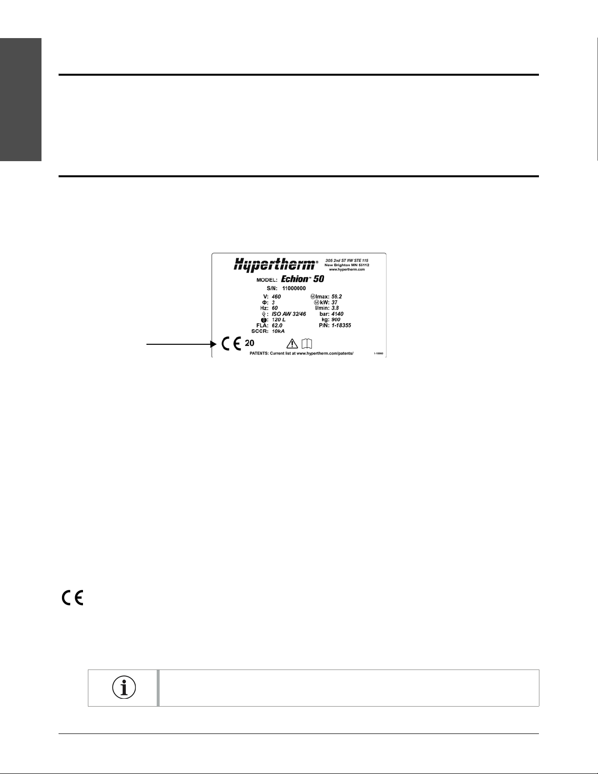
Certification test marks
Certified products are identified by 1 or more certification test marks from accredited testing
laboratories.
The certification test marks are on the pump’s data plate.
Each certification test mark means that the product and its safety-critical parts conform to the
national safety standards as reviewed and determined by that testing laboratory.
Hypertherm puts a certification test mark on its products only after that product is manufactured
with safety-critical parts that have been approved by the accredited testing laboratory.
Once the product has left the Hypertherm factory, the certification test marks are invalid if one or
more of these events occurs.
The product is modified in a manner that causes danger or does not conform with the
applicable standards.
Safety-critical parts are replaced with unapproved spare parts.
Assembly is unauthorized.
An accessory that uses or generates dangerous voltage is added.
A safety circuit or other feature that is designed into the product as part of the certification
has been tampered with.
The Conformité Européene (CE) mark affixed to a product signifies the manufacturer’s declaration
of conformity to applicable European directives and standards.
Only those versions of Hypertherm products with a CE mark on or near the data plate have been
tested for compliance with the applicable European directives, such as the Low Voltage Directive,
the Electromagnetic Compatibility Directive, and the Machinery Directive.
If this product has a Declaration of Conformity, a copy (in English) is included. Refer to
Declaration of Conformity on page 173.
SC-14 810770 Operator Manual Echion

Product stewardship
Differences in national standards
Nations can apply different performance, safety, or other standards. National differences in
standards include, but are not limited to:
voltage.
plug and cord ratings.
language requirements.
electromagnetic compatibility requirements.
Differences in national or other standards can make it impractical or impossible for all certification
test marks to be put on the same version of a product. For example, the Canadian Standards
Association (CSA) versions of Hypertherm’s products do not comply with European
electromagnetic compatibility requirements; therefore, they do not have a CE mark on the data
plate.
Countries where the CE mark in necessary or that have compulsory electromagnetic compatibility
regulations must use CE versions of Hypertherm products with the CE mark on the data plate.
Product stewardship
These could include:
countries in the European Union.
Australia.
New Zealand.
Russia.
It is important that the product and its certification test mark be suitable for the end-use installation
site. When Hypertherm products are shipped to one country for export to a different country, the
product must be correctly configured and certified for the end-use installation site.
Echion Operator Manual 810770 SC-15

Product stewardship
Product stewardship
Higher-level systems
When an original equipment manufacturer (OEM) or a system integrator adds equipment such as
cutting tables, motor drives, motion controllers, or robots to a Hypertherm waterjet cutting system,
the system is considered a higher-level system. A higher-level system with dangerous moving parts
can constitute industrial machinery or robotic equipment, in which case the OEM, system integrator,
or end-use customer can be subject to more regulations and standards than those applicable to the
waterjet cutting system manufactured by Hypertherm.
It is the responsibility of the end-use customer and the OEM or system integrator to do a risk
assessment for the higher-level system and to provide protection against dangerous moving parts.
Unless the higher-level system is certified when the OEM or system integrator incorporates
Hypertherm products into it, the installation can be subject to approval by local authorities. Get
advice from legal counsel and local regulatory experts if you are not sure about compliance.
External cables connecting parts of the higher-level system must be made for exposure to
contamination and movement as necessary for the end-use installation site. When the external
interconnecting cables are subject to exposure to oil, dust, water, or other contamination, hard
usage ratings could be necessary.
When external interconnecting cables are subject to continuous movement, constant flexing ratings
can be necessary. It is the responsibility of the OEM, system integrator, or end-use customer to
make sure that external connecting cables are correct for the application and obey all national, state,
and local regulations.
SC-16 810770 Operator Manual Echion

Environmental stewardship
Environmental stewardship
Echion Operator Manual 810770 SC-17

Environmental stewardship
Environmental stewardship
Hypertherm products: waste and recycling
Hypertherm waterjet cutting systems, like all products with electronics, can contain materials or
parts, such as printed circuit boards, that cannot be discarded with ordinary waste. It is your
responsibility to discard Hypertherm products or parts in an environmentally suitable manner and in
compliance with national and local codes.
In the United States, read all national, state, and local laws. In the European Union (EU), read the EU
directives, national, and local laws. In other countries, refer to national and local laws. Consult with
legal or other compliance experts, when applicable. For information, go to
www.hypertherm.com/customer-support/product-service/recycling.
SC-18 810770 Operator Manual Echion

Environmental stewardship
Chemical handling and usage
Material safety data sheets (MSDS) and safety data sheets (SDS) are part of a hazard
communication plan that supplies detailed information about dangerous chemicals. The information
includes the chemical’s toxicity and reactivity, first aid for exposure, approved storage and disposal,
recommended protective equipment, and spill-handling procedures.
The Occupational Safety and Health Administration (OSHA) has presented new dangerous
chemical labeling requirements as a part of its recent revision of the Hazard Communication
Standard (29 CFR 1910.1200), to align with the United Nations’ Globally Harmonized System of
Classification and Labelling of Chemicals (GHS). The GHS is an international system for
standardizing chemical classification and labeling.
Chemical regulations in the USA, Europe, and other locations require that MSDS and SDS be
made available for chemicals that are supplied with the product and chemicals used in or on the
product. The list of chemicals is supplied by Hypertherm.
To see M S D S a nd S D S:
1. Go to www.hypertherm.com/docs.
Environmental stewardship
2. Look for “To view all regulatory and compliance documents, click here” below the Select your
product box.
3. Look for Safety Data Sheets. Click +.
These navigation instructions can change without notice.
Echion Operator Manual 810770 SC-19

Environmental stewardship
Environmental stewardship
Particle emission and waste water quality
Hypertherm does not manufacture or supply the materials that are cut and has no knowledge about
the particles released from materials that are cut and if they can pose a physical danger or health
risk. Get advice from your supplier or other technical advisor for guidance concerning the properties
of the material you cut with a Hypertherm product.
If you are not familiar with the current applicable government regulations and legal standards for the
installation site, get advice from a local expert before you purchase, install, and operate this
equipment.
SC-20 810770 Operator Manual Echion

Safety
The end user is responsible for the safe operation of this equipment.
Safety
WAR NING
Before operating Hypertherm equipment, read the safety instructions in your product's
manual.
Echion Operator Manual 810770 SC-21

Safety
Safety
Manuals
Copies of Hypertherm manuals can accompany the product in electronic and printed formats.
Copies of the manuals are online, in all languages available for each manual.
1. Go to www.hypertherm.com/docs.
2. Under Select your product, choose Waterjet Family in the dropdown list.
3. Go to the Operator and instruction manuals section and click +.
4. Click on the manual for your product. You may have to click on SHOW ALL at the bottom of the
section.
A PDF of the manual downloads to your device.
These navigation instructions can change without notice.
The safety precautions in this manual are general and cannot anticipate every situation. Hypertherm,
Inc. acknowledges that unforeseen situations such as equipment failure, site variability, insufficient
maintenance, failure of control equipment, and other events can cause equipment damage, injuries,
or death. It is the user’s responsibility to identify dangers and to take the steps necessary to
minimize risks.
Keep these instructions near the equipment. This manual is intended to familiarize the user with the
equipment and its parts, safe operation, and maintenance.
All personnel who operate or have access to this equipment must know this information:
applicable safety standards.
the use, limitations, and maintenance of personal protective equipment.
the location of the written hazard communication program and safety data sheets.
how to recognize dangerous energy sources.
the correct methods for isolating and controlling energy, to include lock out–tag out
procedures.
SC-22 810770 Operator Manual Echion

Safety
User qualification and training
All users must read and understand these instructions before installing, operating, or doing
maintenance on this equipment.
Do not let an untrained person operate this equipment. Operators must be approved to operate and
maintain this equipment.
Training should include:
how to start and stop the equipment during operation and in an emergency situation.
conditions and procedures that can lead to injuries to personnel and damage to the
equipment.
how to operate all controls.
how to identify and respond to a problem with the equipment.
how to do maintenance procedures.
a copy of the operator manual.
Safety
This list is not all-inclusive.
Echion Operator Manual 810770 SC-23

Safety
Safety
Emergency medical information and treatment
WAR NING
A waterjet is a cutting tool.
Keep away from high-pressure streams and leaks. Pressurized fluid can cause injuries.
Delayed treatment can cause injuries or death.
WAR NING
Do not put ice or heat on a waterjet injury.
If possible, use a support to keep injured body parts above heart level.
High-pressure equipment puts the operator and other personnel at risk of contact with
high-pressure water. Possible injuries include eye damage, lacerations, infections, and amputations.
Waterjet operators should have a waterproof emergency medical tag or card that describes the
recommended treatment for high-pressure water injuries. Show the tag or card to emergency
responders and medical professionals.
This wallet-size card can be copied, laminated, and folded.
injuries.
high-pressure waterjet
immediately for all
Get medical treatment
emergency.
injury is a surgical
A high-pressure injection
INFORMATION
MEDICAL
The person with this card has been exposed to a waterjet
of up to4,140bar(60,000psi) and a velocity
of609m/s(2,000feet/second). Abrasive waterjets can
eject water and abrasive materials that can be injected into
body tissues, leading to a dangerous infection.
Skin can appear to be not damaged or show a small
pinhole-sized puncture wound.
The injured area can become swollen, painful, and pale
over the next4to6hours.
Tissue becomes ischemic and necrotic within12hours.
Do not use digital or local nerve blocks.
Give analgesics by mouth or injection.
SC-24 810770 Operator Manual Echion
Consult a surgical specialist immediately for
decompression, removal of foreign materials, and
debridement.
Give broad-spectrum, intravenous antibiotics for
Gram-negative and Gram-positive organisms.
X-ray is the preferred imaging method.
Acute compartment syndrome is possible.
Leave the wound open.
Do not use solvents other than isotonic sodium chloride
solution for irrigating the wound.

Safety
Safety information for operation, maintenance, repair, and installation
Before opening the electrical enclosure or doing maintenance or repairs on this equipment, turn
DANG ER
OFF the electrical power and release water pressure and hydraulic pressure from the system.
Use standard lock out-tag out procedures.
Isolate all sources of electrical, mechanical, hydraulic, pneumatic, chemical, thermal, or other
energy with a lockable energy-isolating device that satisfies national and local requirements.
Safety
WAR NING
WAR NING
WAR NING
WAR NING
WAR NING
WAR NING
Make sure that all connections, fasteners, locking devices, hoses, and fittings are tight before
operation.
Make sure that the shaft access cover and all other safety devices are correctly installed before
operating this machine.
Do not stand in line with high-pressure fittings when operating this equipment.
If a high-pressure fitting fails, it can cause a stream of water or hydraulic fluid to eject from the
system with force.
Do not leave waterjet cutting equipment unattended while it is operating.
During operation, keep a restricted-access area clear that is larger than the maximum movement
range of the cutting equipment’s moving parts.
Let only approved personnel operate this machinery.
WAR NING
WAR NING
WAR NING
Echion Operator Manual 810770 SC-25
Release all high-pressure water before doing work on this equipment.
Do not touch a hot surface.
Water leaking from a high-pressure fitting or the bleed-down valve can be hot.
Obey all safety requirements and applicable safety laws and regulations.
Obey national and local codes regarding installation, repairs, and maintenance of the electrical
and plumbing systems.
All work that requires opening the electrical enclosure or removing covers or panels from this
equipment must be done only by an approved technician.
It is your responsibility to investigate and obey all local codes.

Safety
Safety
WAR NING
WAR NING
WAR NING
WAR NING
A person who works on deenergized machinery can be injured or killed if the machinery is
energized without permission.
All personnel in an area where energy-control procedures are used must receive training for
energy-control procedures.
DANGEROUS VOLTAGE/RISK OF SHOCK
Doing work on this equipment while it is energized is dangerous.
Personnel who maintain and repair this equipment can be injured or killed if dangerous energy is
not controlled.
Injuries can include burns, cuts, fractures, or electrocution.
Before removing a lock-out device:
obey the employer’s energy-control procedure.
examine machines and parts to make sure that they are operational.
make sure that all personnel are safely away from machines.
After removing energy-isolation devices, make sure that all personnel in the area know that the
devices are removed and that the machine is being energized.
To reduce the risk of injuries or death, wear approved protection and obey safety
recommendations when doing work with electricity.
WAR NING
WAR NING
WAR NING
WAR NING
WAR NING
When work must be done in a small space or an area with limited access, the access must not
be blocked by ventilation ducts, hoses, pipes, or other equipment.
Do not block or remove warnings, cautions, or instructions.
Personal protective equipment is recommended.
If you do not use personal protective equipment, there is a risk of injury or death.
High-pressure water can cause eye injuries.
Wear approved eye protection when operating or doing work near this equipment.
This waterjet equipment could make more noise than is permitted by national or local codes.
When this intensifier is operating, the noise level is75dB(A) to85dB(A).
Water flow rate, pipe layout, and the acoustical characteristics of the building have an effect on
noise level.
Long periods of exposure to noise can cause permanent hearing loss.
Wear approved ear protection and control exposure time when operating or doing work near this
equipment.
SC-26 810770 Operator Manual Echion

Safety
Safety
WAR NING
WAR NING
CAUTION
High-pressure water can cause cuts, abrasions, and punctures.
Precision parts can have sharp corners or edges.
Wear approved hand protection when operating or doing work near this equipment and when
touching parts.
Some materials can cause airborne contamination or particles when cut.
Wear approved respiratory protection when operating or doing work near this equipment.
Examine and clean the equipment regularly.
Refer to the Preventive maintenance schedule on page 60.
Do repairs immediately.
Echion Operator Manual 810770 SC-27

Safety
Safety
SC-28 810770 Operator Manual Echion

Symbols and marks
Symbols and marks
Echion Operator Manual 810770 SC-29
Symbols and marks
Symbols and marks
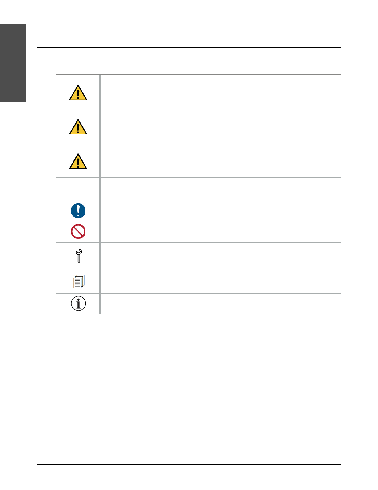
Information and symbols
Some symbols in this table could apply to other products.
DANGER
WAR NING
CAUTION
NOTICE
DANGER identifies an imminently dangerous condition or a situation that WILL cause
serious injuries or death if ignored.
WARNING identifies a dangerous condition or a situation that COULD cause injuries or
death if ignored.
CAUTION, when used with the yellow warning sign, identifies a dangerous condition or a
situation that COULD cause minor or moderate injuries or WILL cause damage to the
equipment if ignored.
NOTICE identifies a condition or a situation that COULD cause damage to the
equipment if ignored.
This symbol identifies a mandatory action.
This symbol identifies a prohibited action.
This symbol identifies tools or materials that are necessary or recommended for a
procedure.
This symbol identifies information that could cause the user to fail at the task if ignored.
This symbol identifies a tip or helpful information.
SC-30 810770 Operator Manual Echion

Symbols and marks
Symbols and marks found on the equipment
Some symbols or marks in this table could apply to other Hypertherm products.
Symbols and marks
DANGER
DANGER ARC FLASH AND SHOCK HAZARD
WAR NING
WAR NING
WAR NING
DANGER identifies an imminently dangerous condition or a situation that WILL cause
serious injuries or death if ignored.
Follow all requirements inNFPA70E for safe work practices and for Personal Protective
Equipment.
WARNING identifies a dangerous condition or a situation that COULD cause injuries or
death if ignored.
HAZARDOUS VOLTAGE
Disconnect power before servicing.
WAR NING
This product can expose you to chemicals including lead and lead compounds, which are
known to the State of California to cause cancer and birth defects or other reproductive
harm.
For more information go to www.p65warnings.ca.gov.
WAR NING
CAUTION
CAUTION
S/N
V
Hydraulic, water, and electrical connections can come loose during shipping and normal
operation.
It is recommended that all connections are checked at installation and annually.
CAUTION, when used with the yellow warning sign, identifies a dangerous condition or a
situation that COULD cause minor or moderate injuries or WILL cause damage to the
equipment if ignored.
Do not touch a hot surface.
Read and fully understand operator’s manual before using this machine.
Failure to follow operating instructions could result in death or serious injury.
Correct direction of motor rotation (motor rotation arrow)
Serial number
Volts
Echion Operator Manual 810770 SC-31

Symbols and marks
Symbols and marks
Φ
HZ
FLA
SCCR
IMAX
KW
L/MIN
BAR
KG
Number of phases in a power system
Frequency (hertz)
Type of hydraulic fluid recommended
Hydraulic fluid tank volume (liters)
Full-load current (amperage)
Short-circuit current rating
Primary motor maximum current draw (amperes)
Primary motor power output (kilowatts)
Maximum outlet flow rate (liters/minute)
Maximum outlet water pressure (bar)
Weight (kilograms)
P/N
Electrical enclosure part number
The Conformité Européene (CE) mark affixed to a product signifies the manufacturer’s
declaration of conformity to applicable European directives and standards.
Only those versions of Hypertherm products with a CE mark on or near the data plate
have been tested for compliance with the applicable European directives, such as the
Low Voltage Directive, the Electromagnetic Compatibility Directive, and the Machinery
Directive.
Use caution when operating this equipment.
Refer to the instruction manual. Read and understand all of the safety guidelines in this
manual.
Identifies the terminal of a protective earth (ground) electrode or a terminal intended to
connect to an external conductor for protection against electric shock during a fault
condition
Controls
Remote key switch off
The key switch is in the Local position.
SC-32 810770 Operator Manual Echion
Remote key switch on
The key switch is in the Remote position.

Symbols and marks
Symbols and marks
COMPRESSED AIR
The bleed-down valve uses compressed air to operate.
CUTTING WATER IN
This line carries low-pressure water from a water softener, a reverse osmosis system, a
well, or a public utility to the pump.
CUTTING WATER OUT
This tubing carries high-pressure water from the intensifier to the cutting table.
WASTE WATER OUT
This hose carries water from the bleed-down valve to a drain.
COOLING IN
This line carries low-pressure water from the local utility or a chiller to the pump’s cooling
loop.
COOLING OUT
This line carries low-pressure water from the heat exchanger to the chiller or to the drain.
Start the pump symbol
Stop the pump symbol
Echion Operator Manual 810770 SC-33

Symbols and marks
Symbols and marks
SC-34 810770 Operator Manual Echion

Optional equipment
Optional equipment
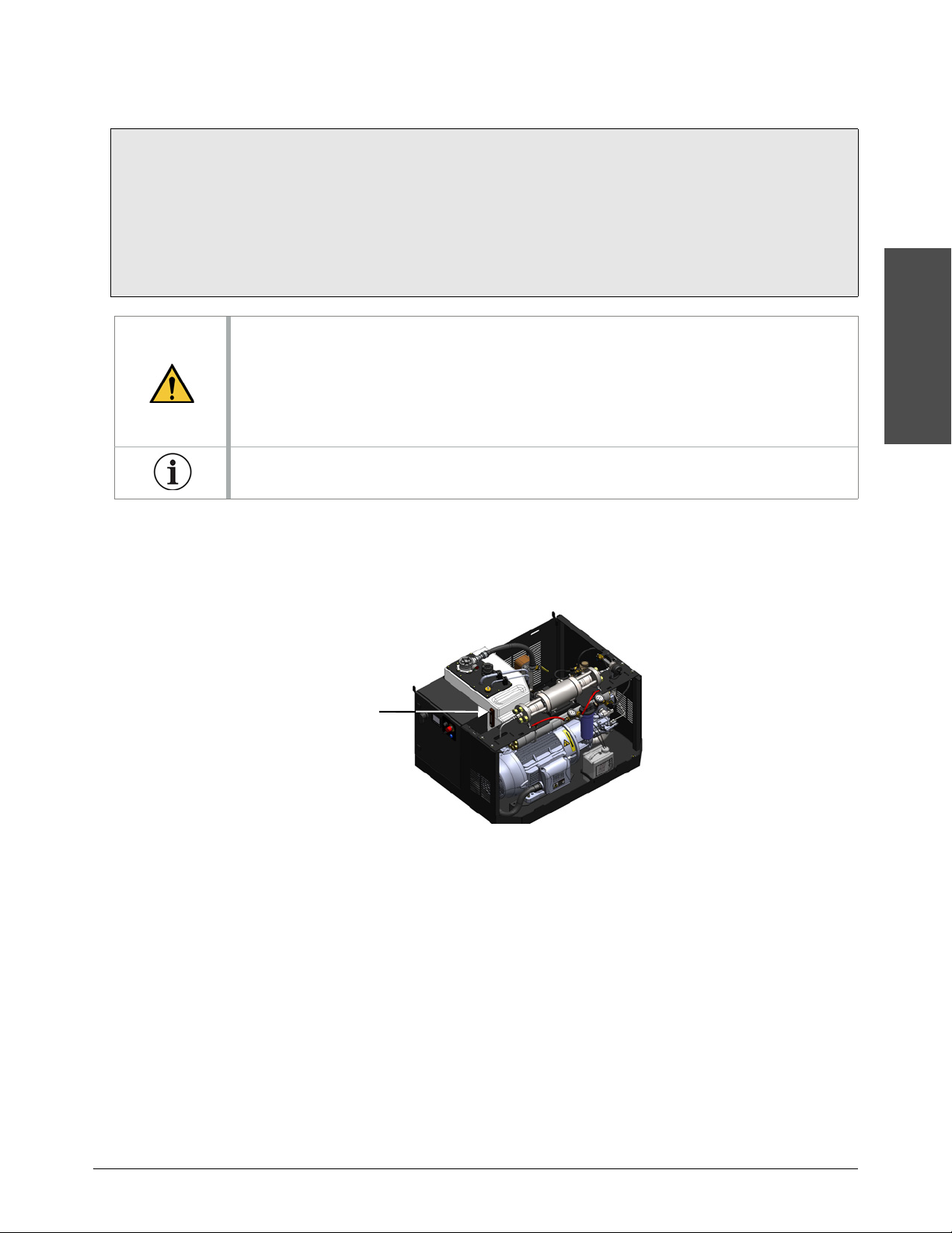
Boost pump
The pump will not operate satisfactorily if the supply water pressure is too low for the pump to get to
stable pressure. A boost pump increases the water pressure to a value higher than the minimum
requirement.
Modbus TCP/IP communication
All Hypertherm waterjet pumps can use Ethernet to communicate with a CNC.
Utility connection panel kit
The utility connections for the Echion pump are inside the pump, at the point of use. With this kit,
utility connections are made on the outside of the pump.
Metric conversion kit
This kit includes adapter fittings for use in countries where metric connections are standard.
Pump-mounted high-pressure plumbing kit
This kit includes a bracket and a high-pressure tube to connect a high-pressure line directly to the
pump.
For part numbers, refer to Optional equipment kits on page 103.
Echion Operator Manual 810770 35

Optional equipment
1
Optional equipment
36 810770 Operator Manual Echion

Operation
Operation
This section assumes that the user is familiar with the Safety, Preventive maintenance,
Troubleshooting, and Specifications sections of this manual.
Images in this manual are for reference purposes. It is possible that your product configuration is
not shown accurately.
It is possible that not all of the information in this section applies to all pump models.
Echion Operator Manual 810770 37

2
Operation
Safety
1
2
3
4
1 Controls button
Push this button to turn
ON the control circuit in
the pump. The button lights when the control
circuit is on.
2 Local/Remote key switch
When the key switch is in the Local
position, use the operator interface to
operate the pump.
When the key switch is in the Remote
position, use the remote source, such as a
computer numerical control (CNC)
operator console, to controls the pump.
Most functions on the operator interface are not
available when the key switch is in the Remote
position.
3 EMERGENCY STOP button
Push this button to turn off the control circuit.
Refer to Emergency stop on page 51.
4 Remote indicator light
When the key switch is in the Remote position, this
indicator light is on.
Operation
WARNING
Read and understand all of the safety guidelines in this manual.
Refer to Safety on page 21 before operating, doing maintenance on, repairing, and installing
your pump.
About the controls
Operation panel
38 810770 Operator Manual Echion

2
Operation
Operator interface
1
2
5
3 4
1 Hour meter
This shows the total hours the pump motor has
been in operation.
2 Primary operation screen tab
• Turn the pump on or off.
• Select the pressure mode (cut or pierce).
• Set or change the water pressure.
• Monitor the status of the intensifier.
3 Operator interface: Adjustment screens tab
• See information about your system.
• Change some display options, such as
pressure units (bar or psi) or language.
• Change timer durations.
• Turn features such as Modbus mode on or
off.
Refer to Operator interface: Adjustment screens
on page 164.
4 Operator interface: Maintenance screens tab
• Move the plunger to one end of the
intensifier.
• Prepare the pump for storage.
• See the alarm log.
• See the inputs-outputs from the controller.
Refer to Operator interface: Maintenance
screens on page 56.
5 Date and time
Refer to Date / Time / Language on page 169.
Refer to Touchscreen maps on page 175 to see all of the screens available on the controller.
Primary operation screen
These elements are on most screens.
Operation
Echion Operator Manual 810770 39

Operation
2
Operation
6
7
8
12
11
9 10
6Stop
Touch this symbol to stop the pump.
7Start
Touch this symbol to start the pump.
8 LED light on/off
Touch this symbol to turn the red LED lights
ON
or
OFF.
9 Pierce-pressure mode (off)
Touch this symbol to put the pump in
pierce-pressure mode.
10 Cut-pressure mode (on)
Touch this symbol to put the pump in
cut-pressure mode.
Cut-pressure mode is active in this
image.
Refer to Select the pressure mode on page 49
for information about pressure modes.
11 Target water pressure
12 Output water pressure
This shows the actual water pressure when the
pump is operating.
This is the target water pressure set by the user.
Refer to Set the target water pressure on
page 49.
3
2
1
1 Intensifier status indicator
Enabled (green)
Not enabled (red)
2 Intensifier stroke rate to the left
3 Intensifier stroke rate to the right
The stroke rate is within the permitted
range (green).
The stroke rate is at the limit of the
permitted range (yellow).
The intensifier is overstroking (red).
Intensifier status indicator and stroke-rate bars
The stroke-rate bars show the speed of the piston moving to each side of the intensifier.
40 810770 Operator Manual Echion
Refer to Primary operation screen on page 113 for more information.

2
Operation
Turn on the pump: beginning of day
2
1
1
2
2
1
2
1
1
2
Follow this procedure when starting the pump for the first time each day or at the beginning of each
work shift. Daily preventive maintenance tasks are included in these instructions.
Inspect the pump
Unless otherwise recommended, install the top cover and the front panel before operating the
pump.
1. Remove the top cover.
Operation
a. Use a standard screwdriver to turn the bolt on each end counterclockwise1/4 turn.
b. Lift the cover off of the alignment pins .
2. Remove the front panel.
Push down on the horizontal surface on top of the panel to release the retainers tabs from the
frame .
Echion Operator Manual 810770 41

Operation
2
Operation
1
2
4
1
2
4
3
3
3. Clean all debris, water, and hydraulic fluid off of the hydraulic fluid tank , the intensifier
bridge , and the bottom deck .
4. Empty the dirty water container , if necessary.
Refer to local regulations regarding waste water. Environmental rules can apply to
disposal.
5. Clean the operator interface, if necessary.
To prevent damage to the operator interface:
do not use cleaners that contain alcohol, ammonia, acetone, phosphates, or
ethylene glycol.
do not push hard on the touchscreen.
do not use paper towels, abrasive cloth, or dirty rags.
do not put liquid directly onto the touchscreen.
Gently wipe the touchscreen and keys with a clean microfiber cloth.
Use a cleaner made for touchscreens or use a1:1 solution of distilled water and white
vinegar.
6. Examine electrical cords and cables for kinks or damage to the insulation. Examine electrical
plugs and other electrical connections for corrosion or damage.
7. Look for leaks, deterioration, damage, or other conditions that can interfere with operation.
8. Make sure that all connections, fasteners, locking devices, hoses, and fittings are tight.
9. Make sure that all warning decals are visible and legible.
Contact Hypertherm for replacement decals.
42 810770 Operator Manual Echion
2
Operation
Check the hydraulic fluid
Replace the hydraulic fluid:
• every 3,000 hours.
• if it is dark or milky in color.
• if it has a strong odor.
• if a test laboratory finds the quality is unsatisfactory.
Refer to Replace the hydraulic fluid on page 86.
Operation
CAUTION
Heat and other conditions cause hydraulic fluid to degrade. Degraded hydraulic fluid can
cause damage to hydraulic components.
Collect a sample of hydraulic fluid from the hydraulic fluid tank and send it to a test
laboratory for analysis.
Refer to Hydraulic fluid on page 136 for recommended limits.
Contact a hydraulic fluid supplier for a precise report about your hydraulic fluid quality.
Do this task when the pump is not operating.
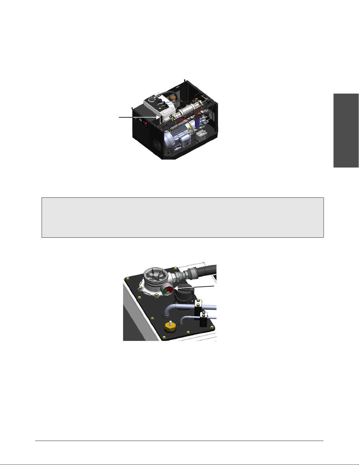
1. Look through the sight gauge to see the color of the hydraulic fluid. Good hydraulic fluid is
almost transparent.
2. Remove the filler cap.
3. Smell the hydraulic fluid. Good hydraulic fluid has almost no odor.
4. Install the filler cap.
Echion Operator Manual 810770 43

Operation
2
Operation
12324
Turn on the utilities
1. Tu rn ON the water to the pump.
2. Tu rn
3. Tu rn
ON the compressed air source.
ON the electrical main (line disconnect switch).
4. Turn the primary breaker disconnect lever on the electrical enclosure door to
Turn on the controls
Turn on the controls remotely
Refer to the OEM’s instructions for starting the pump and for operating the pump from a
remote source.
ON.
1. Make sure that the EMERGENCY STOP is not engaged. If the button is pushed in, turn the
button clockwise until it releases.
2. Make sure that the key switch is set to Local .
3. Push the Controls button .
4. Turn the key switch to Remote . The remote indicator light is on .
44 810770 Operator Manual Echion

2
Operation
Turn on the controls locally
3
2
1
123
1
1
1. Make sure that the EMERGENCY STOP is not engaged. If the button is pushed in, turn the
button clockwise until it releases.
2. Make sure that the key switch is set to Local .
3. Push the Controls button .
Start the pump
Operation
Use the Postmaintenance start procedure on page 91 if maintenance or repairs have been done
CAUTION
on:
• the high-pressure water system.
• intensifier components.
• the primary motor.
1. On the operator interface, touch the symbol.
The controller starts the pump.
A progress bar shows below the intensifier on the screen.
The normal start sequence is fully automated. Refer to Primary operation screen on page 177 for
a description of the sequence.
Monitor for leaks.
2. When the start sequence is complete, complete the Daily preventive maintenance tasks. Refer
to the Preventive maintenance schedule on page 60.
Echion Operator Manual 810770 45
Operation
2
Operation
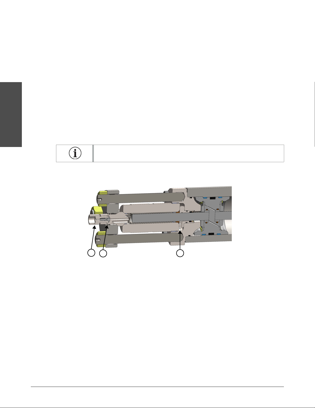
1
2
3
1
Output adapter leak
2
High-pressure seat leak
3
Dynamic seal leak
Do the preoperation maintenance checks
Examine the pump for leaks or damage
Do this task when the pump is operating and the system is pressurized.
1. Look for hydraulic fluid leaks. Monitor these areas.
Hydraulic connections
Valves
Intensifier bridge and bottom deck
2. Examine the low-pressure tubes and the hoses for leaks.
3. Examine the bleed-down valve for leaks or damage.
A hot bleed-down valve can suggest that there is a leak.
4. Examine the weep holes in the high-pressure ends for leaks. Water leaking from a weep hole is
a sign of a faulty part or a loose connection.
5. Examine the high-pressure tubing for leaks.
6. Look for deterioration, damage, or other problems.
46 810770 Operator Manual Echion
2
Operation
Check the hydraulic fluid level
Do this task when the pump is operating.
Make sure that the hydraulic fluid level is at the top mark on the sight gauge.
Add hydraulic fluid, if necessary. Refer to Add hydraulic fluid on page 85 for instructions.
Check the hydraulic filter gauge
Operation
Replace the hydraulic filter element:
• every 1,500 hours.
• when the needle on the gauge stays in the red zone while the pump is operating.
Refer to Replace the hydraulic filter element on page 84.
Do this task when the pump is operating at a stable temperature.
Make sure that the needle on the hydraulic gauge is not in the red zone.
Echion Operator Manual 810770 47
Operation
2
Operation
1
2
1
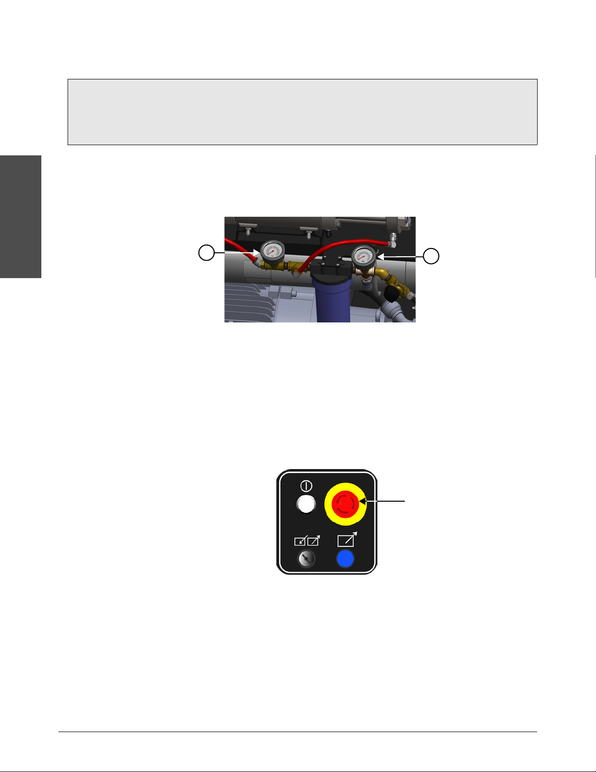
Postfilter water-pressure gauge
2
Prefilter water-pressure gauge
Check the low-pressure water pressure gauges
Replace the water filter:
• every 1,000 hours.
• if the difference between the values is more than0.7bar(70kPa/10psi).
Refer to Replace the water filter on page 80.
The prefilter water-pressure gauge shows the water pressure before the water goes through the
filter. The postfilter water-pressure gauge shows the water pressure after the water goes through
the filter.
The usual range is2.8bar to7.6bar (280kPa to760kPa/40psi to110psi).
Do this task when the pump is operating.
Subtract the value shown on the postfilter water pressure from the value shown on the prefilter
water pressure.
If the difference between the values is more than0.7bar(70kPa/10psi), replace the water filter.
Make sure that the emergency stop operates correctly
Do this task when the pump is operating.
On the operation panel, push the EMERGENCY STOP button. Refer to Emergency stop on
page 51.
48 810770 Operator Manual Echion

2
Operation
Operate the pump
4
1
2 3
1 Target water pressure
Touch this to set the target water pressure.
2 Pierce-pressure mode (off)
Touch this symbol to put the pump in
pierce-pressure mode.
3 Cut-pressure mode (on)
Touch this symbol to put the pump in cut-pressure
mode.
4 Output water pressure
This shows the actual water pressure when the
pump is operating.
3
2
1
Operation
Select the pressure mode
Cut-pressure mode is used for most cutting jobs.
Pierce-pressure mode (low-pressure mode) is applicable for:
making a hole in the material to be cut.
decreasing the risk of cracking when cutting brittle materials, such as glass or ceramic.
preventing composite materials like carbon fiber from delaminating.
Pierce pressure is typically less than or equal to1,380 bar(138,000kPa/20,000psi).
Set the target water pressure
There are2 ways to change the target water pressure on the operator interface.
Touch the symbol or the symbol to change the target water pressure in preset
increments.
To change the increments, refer to Pressure Adjustments on page 167.
Touch the target water pressure button to open a numeric keypad. Type the number and
then touch Enter.
Echion Operator Manual 810770 49

Operation
2
Operation
Stop the pump
Stop the pump remotely
You can stop the pump from the operator interface while using remote controls. On the
operator interface, touch the symbol to stop the pump.
Refer to Stop the pump on page 50.
Refer to Emergency stop on page 51 for information about the EMERGENCY STOP button.
Refer to the OEM’s instructions for turning the pump off.
Stop the pump locally
Use this procedure during normal operation.
On the operator interface, touch the symbol.
The pump, the primary motor, and the intensifier turn off.
The bleed-down valve opens to release high-pressure water from the system.
The supply-water valve closes to stop low-pressure water from entering the system.
No output water pressure shows.
The control circuit stays on.
50 810770 Operator Manual Echion

2
Operation
Emergency stop
Operation
WAR NING
The EMERGENCY STOP button does not disconnect main electrical power from the
machine.
Use the emergency stop to stop the controls immediately to prevent injury or to reduce the risk of
injury to personnel, machinery, or work in progress. This is not the preferred method of turning
off the pump.
On the operation panel, push the EMERGENCY STOP button.
The control circuit turns off, which turns off the pump, the primary motor, and the intensifier.
Remote controls that are wired to the pump controller turn off.
The bleed-down valve opens to release high-pressure water from the system.
The supply-water valve closes to stop low-pressure water from entering the system.
The EMERGENCY STOP button must be reset before the equipment can be turned on.
Turn the button clockwise until it releases.
Echion Operator Manual 810770 51

Operation
2
Operation
124
1
2
4
3
3
Turn off the pump: end of day
Do this procedure at the end of the day.
1. On the operator interface, touch the symbol to stop the pump.
2. Turn the primary breaker disconnect lever on the electrical enclosure door to
3. Tu rn
OFF the utility water to the pump. Make sure that the water pressure gauges
OFF.
show0.0bar(0kPa/0psi).
4. Tu rn
5. Tu rn
OFF the compressed air source.
OFF the electrical main (line disconnect switch). Use standard lock out–tag out procedures.
6. Remove the top cover and the front panel.
7. Clean all debris, water, and hydraulic fluid off of the hydraulic fluid tank , the intensifier
bridge , and the bottom deck .
8. Empty the dirty water container , if necessary.
Refer to local regulations regarding waste water. Environmental rules can apply to
disposal.
52 810770 Operator Manual Echion

Preventive maintenance
Preventive maintenance
This section assumes that the user is familiar with the Safety, Operation, Troubleshooting, and
Specifications sections of this manual.
Images in this manual are for reference purposes. It is possible that your product configuration is
not shown accurately.
It is possible that not all of the information in this section applies to all pump models.
Echion Operator Manual 810770 53

3
Preventive maintenance
Safety
Preventive maintenance
WAR NING
CAUTION
CAUTION
CAUTION
CAUTION
Read and understand all of the safety guidelines in this manual.
Refer to Safety on page 21 before operating, doing maintenance on, repairing, and installing
your pump.
Do not tighten a fitting too much. The fitting can fail.
Hydraulic, water, and electrical connections can become loose during shipping and normal
operation. Examine all connections at installation and during regular maintenance.
When replacing wiring, use only the same size, type, and color as the original wiring.
Before assembling high-pressure or hydraulic parts, clean the parts to remove grease and other
contamination.
Clean and examine parts that will be replaced to identify wear patterns or damage that can show
other problems.
Clean each part with a towel and isopropyl alcohol. Examine all parts for deterioration, corrosion,
or damage.
Do not use soap, detergent, or solvents.
Keep the work area clean and dry. Clean fluid spills immediately.
Use a pan or a tray below areas where water or hydraulic fluid can spill during maintenance or
repair procedures.
Obey local protocols for recycling or disposal of parts, materials, and fluids.
National and local environmental rules can apply to disposal.
Refer to Recycling and end of product life on page 96.
Keep accurate maintenance records. Records can help with predicting and preventing
maintenance problems.
Keep spare parts and repair kits available.
54 810770 Operator Manual Echion

3
Preventive maintenance
Benefits of preventive maintenance
Hypertherm recommends preventive and scheduled maintenance for Echion pumps. High-quality
equipment that is maintained on a schedule lasts longer than equipment that is not maintained
regularly. This maintenance includes adjustments, cleaning, lubrication, repairs, and replacement of
parts.
Improves reliability
Finds possible problems before they cause unplanned downtime and become expensive
repairs
Extends the life of equipment and decreases the frequency of replacement
Contributes positively to reputation and profits
Gives traceability through records
Training
Preventive maintenance
The employer must provide training for maintenance procedures. Retrain personnel when:
there is a change in job assignment, machinery, or procedures that can present a new
danger.
energy-control procedures change.
there is reason to believe there is a deficiency in a person’s knowledge of the energy-control
procedure.
Echion Operator Manual 810770 55

Preventive maintenance
3
Preventive maintenance
2
41
5
3
1
Move the plunger
2
Start the pump after maintenance
3
Prepare for storage
4
Inputs and outputs
5
Alarm log
Operator interface: Maintenance screens
Refer to Touchscreen maps on page 177 to see all of the screens available on the controller.
On the operator interface, touch the maintenance tab to open the primary maintenance screen.
Move the plunger
Touch this symbol to open the Move the Plunger screen.
Instructions for moving the plunger begin on page 61.
56 810770 Operator Manual Echion

3
Preventive maintenance
Start the pump after maintenance
Touch this symbol to open the Start Procedure screen.
Refer to Postmaintenance start procedure on page 91 for more information.
Prepare for storage
Preventive maintenance
Touch this symbol to open the Prepare for Storage screen.
Refer to Prepare for storage on page 93 for more information.
Echion Operator Manual 810770 57

Preventive maintenance
3
Preventive maintenance
Inputs and outputs
The inputs and outputs screen is useful for troubleshooting. Touch this symbol to open a screen that
shows inputs and outputs for the controller.
Refer to Input/output status on page 134 for more information.
Alarm log
The alarm log is useful for troubleshooting. Touch this symbol to open the Alarm Log screen.
Refer to Alarms on page 114 for more information.
58 810770 Operator Manual Echion

3
Preventive maintenance
Tools
1
3
2
Preventive maintenance
Use the correct tools for maintenance procedures. Some tools are designed to make the
procedure easier and to prevent damage to the equipment.
Personnel who maintain and repair this equipment must know how to use standard hand tools.
Use SAE (US standard) tools for most procedures.
Special tools are recommended or necessary for some maintenance and repair procedures.
Open-ended wrench
Crowfoot wrench
Screwdriver
Standard
Phillips
O-ring pick
Snap ring pliers
Intensifier repair tools
1
Seal installation tool
2
Seal removal tool
3
Cylinder locator tool
Echion Operator Manual 810770 59

Preventive maintenance
3
Preventive maintenance
Preventive maintenance schedule
These maintenance intervals are recommended guidelines. Find the procedures on the page
numbers listed in the Hours columns.
Before starting the pump
Clean and inspect the pump.
Check the hydraulic fluid.
After starting the pump
Examine the pump for leaks or damage.
Check the hydraulic fluid level.
Check the hydraulic filter gauge.
Check the low-pressure water pressure gauges.
Make sure that the emergency stop operates correctly.
Daily
page
39
page
41
page
44
page
45
page
45
page
46
page
46
Interval
500
1,000
3,000
1,500
6,000
12,000
Intensifier
Repair the high-pressure cylinders, the check valves,
and the low-pressure poppets.
Replace the high-pressure seal cartridges.
Intensifier
Replace the high-pressure poppet assemblies.
Replace the low-pressure poppets and seats.
Low-pressure water system
Clean the air cooler.
Bleed-down valve
Repair the bleed-down valve.
Low-pressure water system
Replace the water filter.
Test the low-pressure water TDS level.
page
66
page
69
page
69
page
74
page
78
page
75
page
80
page
81
60 810770 Operator Manual Echion

3
Preventive maintenance
Hydraulic system
Replace the hydraulic filter element.
Intensifier
Flip the high-pressure cylinder.
Intensifier
Preventive maintenance
Interval
500
Daily
1,000
page
84
page
66
1,500
3,000
6,000
12,000
Replace the high-pressure cylinders and the check valve
assemblies.
Bleed-down valve
Replace the bleed-down valve body.
Hydraulic system
Replace the hydraulic fluid.
Intensifier
Replace the output adapters.
Replace the seal housing assemblies.
Motor
Lubricate the primary motor bearings.
Intensifier
Replace the spacer tubes.
Repair the hydraulic center section.
page
66
page
75
page
86
page
73
page
62
page
88
page
62
page
65
Echion Operator Manual 810770 61

Preventive maintenance
3
Preventive maintenance
1
2
4
3
6
5
7
1 Output adapter and high-pressure poppet
assembly
2 Check valve assembly
3 Spacer tube
4 High-pressure cylinder
5 Seal housing assembly
6 Plunger
7 Hydraulic center section
Intensifier
Every 500 hours
• Repair the check valves and the low-pressure
poppets.
• Repair the high-pressure cylinders.
• Replace the high-pressure seal cartridges.
Every 1,000 hours
• Replace the high-pressure poppet assemblies.
• Replace the low-pressure poppets and seats.
Every 1,500 hours
• Flip the high-pressure cylinders.
CAUTION
CAUTION
To prevent causing damage or premature failure, use 2 wrenches when loosening or tightening
a high-pressure connection.
Always tighten fittings to the specified torque.
Do not use an adjustable wrench on high-pressure fittings.
Every 3,000 hours
• Replace the high-pressure cylinders.
• Replace the check valve assemblies.
Every 6,000 hours
• Replace the output adapters.
• Replace the seal housing assemblies.
Every 12,000 hours
• Replace the spacer tubes.
• Repair the hydraulic center section.
Use clean hands when changing high-pressure parts.
To reduce downtime, Hypertherm recommends doing preventive maintenance on both ends of
the intensifier at the same time.
62 810770 Operator Manual Echion

3
Preventive maintenance
Parts, tools, and materials
Intensifier repair tools
1-18770 Echion high-pressure seal repair kit
1-18771 Echion high-pressure poppet repair kit
1-18849 Echion low-pressure poppet repair kit
1-18768 Standard tool kit
13/16-inch open-ended wrench or socket
1-inch open-ended wrench
1-1/16-inch open-ended wrench
1-inch socket
Torque wrench
Rubber mallet
2 O-ring picks (or similar tool)
2 standard screwdrivers
Large snap-ring pliers
Small snap-ring pliers
Isopropyl alcohol
Antiwear (AW) mineral oil or synthetic hydraulic
fluid, ISO viscosity grade (VG) 32 or 46
Clean towels
Nonstick scouring pad
Masking tape
Recommended materials
Bench vise
Preventive maintenance
Refer to Intensifier high-pressure ends on page 107 for individual replacement parts.
Do this task when the pump is not operating.
1. On the operator interface, touch the maintenance symbol to open the primary maintenance
screen.
2. Touch this symbol to open the Move the Plunger screen.
3. Touch the motor symbol to start the motor.
Echion Operator Manual 810770 63

Preventive maintenance
3
Preventive maintenance
4. Touch a symbol to move the intensifier plunger to the end you will be working on.
5. On the operator interface, touch the symbol to stop the pump.
6. Turn the primary breaker disconnect lever on the electrical enclosure door to
7. Tu rn
OFF the utility water to the pump. Make sure that the water pressure gauges
OFF.
show0.0bar(0kPa/0psi).
8. Tu rn
9. Tu rn
OFF the compressed air source.
OFF the electrical main (line disconnect switch). Use standard lock out–tag out procedures.
10. Use a 13/16-inch open-ended wrench to disconnect the high-pressure tubing from the
intensifier.
11 . Remove the bleed-down valve. Refer to step 5 though step 10 on page 76.
12. Push the button on the quick-disconnect fitting to remove the low-pressure water line from the
intensifier.
It is possible that some water will spray from the connection when this tubing is
disconnected.
13. Use the breaker bar and the1-1/2-inch12-point socket to remove the endcap nuts. Use a
repeating cross pattern.
14. Remove the end cap.
Hydraulic fluid and water will leak during this procedure. Put towels on the intensifier
bridge under the work area.
64 810770 Operator Manual Echion

3
Preventive maintenance
15. Pull out the check valve.
16. Pull the high-pressure cylinder off of the plunger.
Make sure that the spacer tube does not fall out. Dropping the spacer tube can cause
damage to it.
17. Put the cylinder locator tool and the seal installation tool together.
18. Put the tool on the seal housing and turn it clockwise so that the threads engage. Pull the seal
housing assembly off of the plunger.
A small amount of hydraulic fluid could leak from the hydraulic cylinder. This is normal.
Repair the hydraulic center section
Preventive maintenance
Repair the hydraulic center section every 12,000 hours.
The hydraulic center section includes the piston, the hydraulic cylinder, the hydraulic end caps, the
low-pressure seals, the plungers, the T-seals, and the proximity switches.
Preventive maintenance on these parts requires special tools. Contact a Hypertherm Technical
Service Associate for information and support regarding the installation, operation, maintenance,
and repair of this equipment.
Echion Operator Manual 810770 65

Preventive maintenance
3
Preventive maintenance
7
2
6
1
4
3
5
8
1
Check valve body
2
Low-pressure poppet
3
Check valve wear ring
4
Poppet retainer
5
Low-pressure poppet screw
6
Spacer tube
7
High-pressure cylinder
8
High-pressure seal cartridge
Repair the high-pressure cylinder, the check valve, and the low-pressure poppet
Repair the high-pressure cylinders every 500 hours.
Repair the check valves and the low-pressure poppets every 500 hours.
Replace the high-pressure seal cartridges every 500 hours.
Replace the low-pressure poppets and seats every 1,000 hours.
Replace the high-pressure cylinders every 3,000 hours or if the cylinder is chipped or cracked.
Replace the check valve assemblies every 3,000 hours.
CAUTION
Debris in the cylinder can cause the seals or the poppets to fail.
This procedure is for a moderately worn check valve. Replace very worn components.
1. Disassemble and examine the cylinder and the check valve.
66 810770 Operator Manual Echion
2. Disassemble the cylinder locator tool and the seal installation tool.
3. Put the high-pressure cylinder on the seal locator tool. Make sure that the spacer tube is inside
the cylinder.

Preventive maintenance
3
Preventive maintenance
4. Put the end of the push tool against the spacer tube inside the cylinder.
5. Tap on the end of the push tool with a rubber mallet to push the bottom seal and the hoop out of
the high-pressure cylinder.
6. Take the spacer tube out of the cylinder.
7. Disassemble all of the parts.
8. Examine the cylinder. If the area around the bore is marked or pitted or has rough edges or
burrs, remove the defects with a nonstick scouring pad.
9. Cut a nonstick pad in half. Put half of the pad in the end of the cylinder. Put 1 thumb in each end
of the cylinder and push down evenly on the pad while rolling the cylinder back and forth.
Nonstick scouring pad
10. Clean the inner surfaces of the cylinder with a towel and isopropyl alcohol.
11 . Use a 1/8-inch hex wrench to remove the low-pressure poppet screw from the check valve.
12. Tape a sheet of lapping paper on a granite lapping block. Make sure that the paper is smooth
and flat.
Echion Operator Manual 810770 67

Preventive maintenance
3
Preventive maintenance
13. Put the check valve face or the low-pressure poppet face flat on the lapping paper and move it
back and forth. Use light pressure. Do this procedure until the face is smooth and flat and has a
mirrorlike finish.
CAUTION
CAUTION
Do not rock the parts or use too much pressure. Doing so can cause damage to the
part faces.
Keep the low-pressure poppet and the poppet retainer clean. Grease can cause the
poppet to stick.
Do not put grease or lubricant on the check valve face or in the cylinder bore. These
components are designed for dry contact.
68 810770 Operator Manual Echion

3
Preventive maintenance
Install the high-pressure components
1
2
3
1
4
6
5
1
Seal housing
2
O-ring backup
3
O-ring
4
Energized spring seal
5
Rod seal spacer
6
Snap ring
Replace the seal housing assemblies every 6,000 hours.
Preventive maintenance
CAUTION
Water can enter the hydraulic system if the weep holes in the dynamic seal backup or the seal
housing are blocked. Make sure that there is no debris in the weep holes.
1. Use small snap-ring pliers to remove the snap ring from the seal housing.
2. Remove the rod seal spacer.
3. Use an O-ring pick to remove the energized seal spring.
4. Remove the O-ring and the O-ring backup from the seal housing.
5. Clean all surfaces. Examine the seal housing and the high-pressure seal backup. Make sure that
the inner grooves are clean.
Make sure that the weep hole is clear. If necessary, use compressed air to blow debris out.
6. Put high-vacuum grease on the backup ring and the seal housing O-ring.
Echion Operator Manual 810770 69

Preventive maintenance
3
Preventive maintenance
1
2
1
2
7. Put the seal housing O-ring backup and the seal housing O-ring on the seal housing.
The seal housing O-ring backup has a flat side and a concave side. Make sure the flat side of
the O-ring backup faces the wide end of the seal housing. The O-ring fits into the concave
groove on the O-ring backup.
8. Put the new components in the seal housing, as shown.
9. Use snap-ring pliers to insert the snap ring. Make sure that the snap ring is seated correctly in
the groove.
10. Put the cylinder locator tool and the seal installation tool together.
11 . Put the tool on the seal housing and turn it clockwise so that the threads engage.
12. Put the seal housing on the plunger with the narrow end of the seal housing toward the center
of the intensifier.
13. Turn the seal housing so that the weep hole faces down.
14. Push the seal housing tightly against the hydraulic end cap. You should feel it click.
15. Remove the tool from the seal housing.
70 810770 Operator Manual Echion
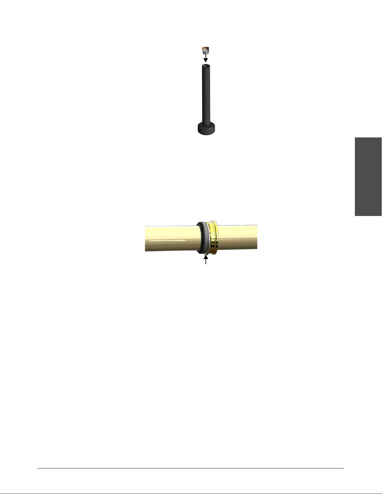
Preventive maintenance
3
Preventive maintenance
16. Put the cartridge in the seal installation tool.
17. Hold the seal installation tool with both hands and push the cartridge and the tool onto the
plunger in a smooth motion. Push until the cartridge is touching the seal housing.
18. Remove the seal installation tool, leaving the cartridge on the plunger.
Part of the cartridge stays inside the seal installation tool. This is by design.
19. Make sure that the cartridge parts are tight and none of the components are hanging down on
the plunger.
20. Put the spacer tube on the plunger.
21. Find the end of the high-pressure cylinder that was repaired with the nonabrasive pad. Put the
high-pressure cylinder over the spacer tube with that end facing the center of the intensifier.
Push the cylinder as far as possible.
Turn the high-pressure cylinder around at 1,500 hours to promote even wear.
22. Put the check valve in the end of the high-pressure cylinder. Make sure that the weep hole faces
down toward the ground.
23. Put the high-pressure end cap over the check valve and onto the studs. Push the endcap until it
is tight against the check valve. Make sure that the low-pressure water connection points
toward the attenuator.
24. Use a clean rubber mallet to tap the exposed part of the check valve until the cylinder is fully
seated in the end of the hydraulic end cap.
25. Lubricate the stud threads with antiseize bolt lubricant (white lithium grease).
Echion Operator Manual 810770 71

Preventive maintenance
3
Preventive maintenance
26. Put the nuts on the studs by hand. Use a torque wrench to tighten the high-pressure end cap
nuts to68N ∙ m(5 0lbf ∙ ft).
Use a repeating cross pattern.
Tighten the nuts to375N ∙ m(275lbf ∙ ft). Do this in6 8N ∙ m(50lbf ∙ ft) increments.
72 810770 Operator Manual Echion

3
Preventive maintenance
Examine the output adapter and the high-pressure poppet assembly
1
2
3
4
1
High-pressure poppet seat
2
High-pressure poppet
3
High-pressure poppet spring
4
Output adapter
Replace the high-pressure poppet assemblies every 1,000 hours.
Replace the output adapters every 6,000 hours.
Preventive maintenance
CAUTION
The high-pressure poppet seat can cause cracks, erosion marks, or dents in the output adapter.
If a poppet part is damaged, replace all 3 components.
Use a cotton-tipped applicator to guide the high-pressure poppet seat out of the check valve.
Tap the output adapter gently on a wooden or other soft surface to eject the poppet from the output
adapter.
Echion Operator Manual 810770 73

Preventive maintenance
3
Preventive maintenance
Assemble the check valve and the low-pressure poppet
1. Use a cotton-tipped applicator to put high-pressure antiseize lubricant in the recess in the
bottom of the check valve.
2. Use a cotton-tipped applicator to guide the high-pressure poppet seat into the check valve. The
wide end of the poppet seat faces toward the check valve.
3. Push the high-pressure poppet seat into the high-pressure antiseize lubricant in the check valve.
4. Put high-pressure antiseize lubricant on the threads of the output adapter.
5. Put the high-pressure poppet spring and the high-pressure poppet in the output adapter.
6. Put the output adapter in the check valve and tighten it by hand. Use a torque wrench to tighten
the output adapter to 115 N ∙ m (85 lbf ∙ ft).
Tightening the output adapter with the high-pressure poppet in an incorrect position
can cause damage.
When the output adapter is correctly installed, the gap between the wide part of the
output adapter and the check valve is2.5mm(3/32inch) and no threads are visible.
CAUTION
If the gap is too large or if threads are visible, make sure that the poppet parts have
not moved.
7. Torque the high-pressure water fitting to 68 N ∙ m (50 lbf ∙ ft).
8. Repeat this procedure on the other end of the intensifier.
9. Connect the high-pressure tubing.
CAUTION
Make sure that some of the threads on the high-pressure tubing are visible at the
fitting. Refer to High-pressure water fittings on page 144.
10. Connect the low-pressure water lines.
74 810770 Operator Manual Echion
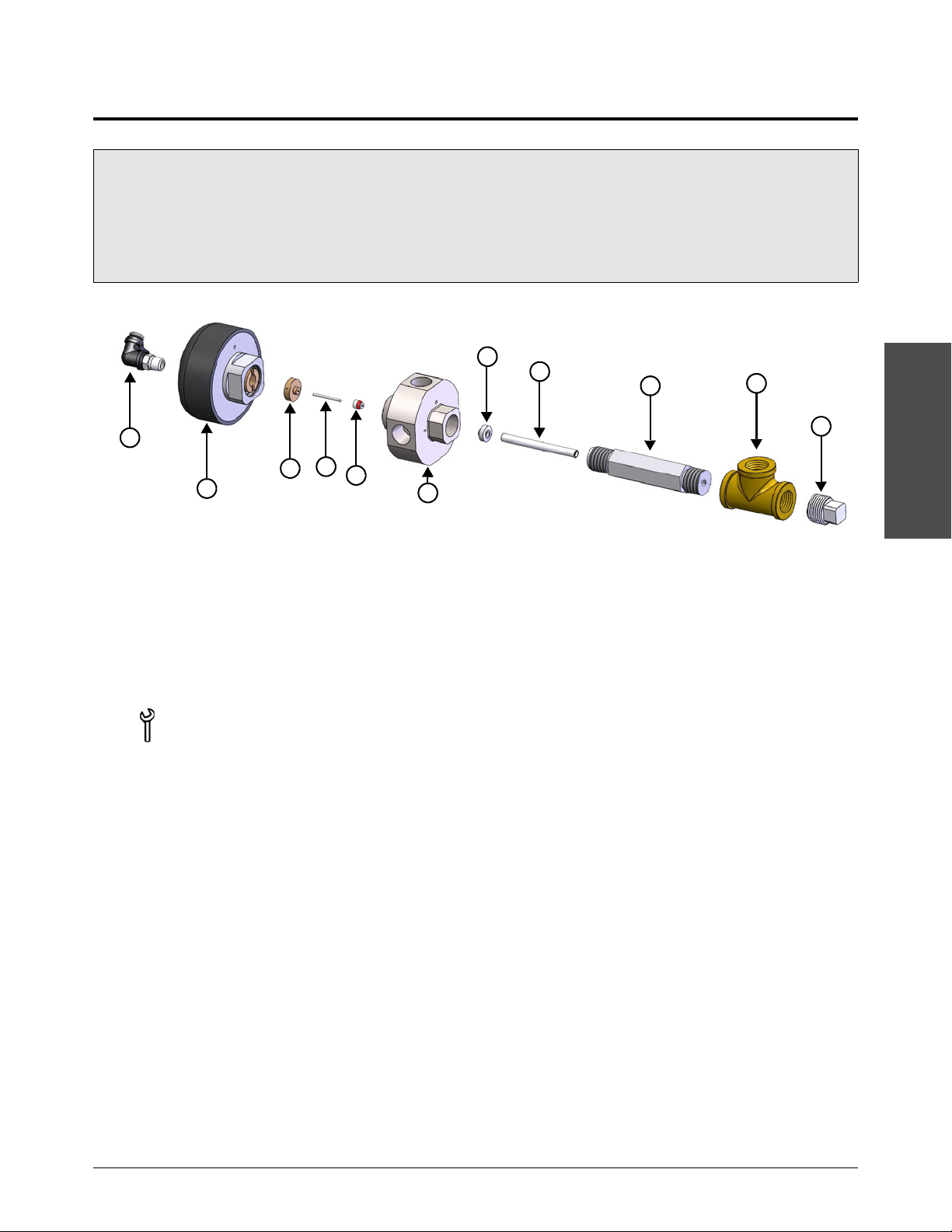
Preventive maintenance
3
Preventive maintenance
1
2
3
5
6
7
8
9
10
4
11
1 Air fitting
2 Actuator
3 Needle guide
4 Needle
5 High-pressure valve seal
6 Bleed-down valve body
7 Bleed-down valve seat
8 Flow reducer
9 Outlet adapter
10 Tee fitting
11 Plug
1-17434 Bleed-down valve repair kit
1-18311 Bleed-down valve body
3/4-inch open-ended wrench
5/8-inch open-ended wrench
13/16-inch open-ended wrench
1-inch open-ended wrench
1-1/8-inch open-ended wrench
13/16-inch crowfoot wrench
Torque wrench
Clean towels
Isopropyl alcohol
Repair the bleed-down valve
Repair the bleed-down valve:
every 1,000 hours.
if water leaks from the Waste water out connection or from the weep holes while the pump is operating.
Replace the bleed-down valve body every 3,000 hours.
Parts, tools, and materials
Do this task when the pump is not operating.
1. Turn the primary breaker disconnect lever on the electrical enclosure door to OFF.
2. Tu rn
3. Tu rn
Echion Operator Manual 810770 75
4. Tu rn
OFF the utility water to the pump. Make sure that the water pressure gauges
show0.0bar(0kPa/0psi).
OFF the compressed air source.
OFF the electrical main (line disconnect switch). Use standard lock out–tag out procedures.

Preventive maintenance
3
Preventive maintenance
5. Remove the top cover and the front panel. Refer to Inspect the pump on page 39 for
instructions.
6. Disconnect the compressed air hose from the air fitting on top of the actuator.
7. Disconnect the water drain tube from the bleed-down valve.
8. Use 13/16-inch open-ended wrench to loosen the high-pressure fittings attached to the
bleed-down valve body.
9. If the pump-mounted plumbing kit is installed on this machine, loosen the high-pressure fitting
near the bleed-down valve.
10. Remove the bleed-down valve assembly from the pump.
11 . Remove the outlet adapter from the valve body.
12. Remove the seat and the flow reducer from the outlet adapter.
13. Remove the actuator from the valve body.
14. Push a dowel through the bottom of the valve body to remove the seal, the needle guide, and
the needle.
15. Put high-pressure antiseize lubricant on the seat.
16. Put the flow reducer into the outlet adapter.
17. Put the seat into the outlet adapter.
18. Install the outlet adapter in the bleed-down valve body. Use a torque wrench to tighten the
adapter to95N∙m(70lbf∙ft).
19. Put the needle through the needle guide and the valve seal. Make sure that the point of the
needle faces the seal.
20. Put high-vacuum grease on the red O-ring on the valve seal. Make sure that the red O-ring on
the valve seal faces away from the needle.
76 810770 Operator Manual Echion

Preventive maintenance
3
Preventive maintenance
21. Put the needle-and-seal assembly into the valve body until the needle guide is even with the top
of the bore.
22. Install the actuator on the valve body. Tighten the actuator by hand.
23. Use a torque wrench to tighten the high-pressure fittings on the valve body. Refer to
High-pressure water fittings on page 144.
24. Connect the water drain tube to the bleed-down valve.
25. Connect the compressed air hose to the fitting on top of the actuator.
26. Tu rn
27. Tu rn
28. Tu rn
29. Turn the primary breaker disconnect lever on the electrical enclosure door to
ON the utility water to the pump.
ON the compressed air source.
ON the electrical main (line disconnect switch).
ON.
30. Make sure that the EMERGENCY STOP is not engaged. If the button is pushed in, turn the
button clockwise until it releases.
31. Make sure that the key switch is set to Local .
32. Push the Controls button.
33. On the operator interface, touch the symbol to start the pump.
34. Monitor for leaks.
Echion Operator Manual 810770 77

Preventive maintenance
3
Preventive maintenance
Compressed air source
Pressurized-water source or a steam cleaner
Operation or equivalent oil
Recommended materials
Aluminum-compatible detergent
Ethylene perchlorate detergent
Oil carbon detergent
Clean the air cooler
Do this task:
every 1,000 hours.
if you receive a Fault 1: Hydraulic Fluid>65C alarm.
CAUTION
CAUTION
Detergent can give better cleaning results. Think about the environment when selecting and
using cleaning chemicals.
Detergent must be compatible with aluminum.
Protect the motor and all electronics during the cleaning procedure.
Parts, tools, and materials
Do this task when the pump is off.
Remove the top cover and the front panel. Refer to Inspect the pump on page 39 for instructions.
Clean the air side of the cooler
CAUTION
CAUTION
To prevent damage, the stream of water or air must be parallel to the fin.
Point the water stream against the air direction.
Detergent can give better cleaning results. Think about the environment when selecting and
using cleaning chemicals.
Detergent must be compatible with aluminum.
1. Refer to the label on the cooler to find the cooler’s air direction.
2. Clean oil and grease off of the cooler with compressed air, pressurized water, or a steam
cleaner. Direct the cleaning stream against the cooler’s air direction.
78 810770 Operator Manual Echion
3. After cleaning, dry the cooler.

3
Preventive maintenance
Clean the hydraulic fluid side of the cooler
1. Disassemble the blast oil cooler to find the degree of contamination.
If contamination is moderate, connect the oil side to a closed cleaning system with a pump and
a filter.
Ethylene perchlorate detergent can be used. Pump the detergent through the blast oil
cooler for10 minutes.
If contamination is very bad, use an oil carbon detergent. Rinse cleaned surfaces for30 minutes.
2. Use compressed air to remove remaining detergent.
3. Rinse the blast oil cooler with operation or equivalent oil.
Preventive maintenance
Echion Operator Manual 810770 79

Preventive maintenance
3
Preventive maintenance
Filter cartridge, water, 1.0 micron, 10-inch
Filter wrench (included in the standard tool kit)
Recommended materials
Bucket or pail
Replace the water filter
Do this task:
every 1,000 hours.
if the difference between the values on the prefilter water-pressure gauge and the postfilter water-pressure
gauge is more than 0.7bar(70kPa/10 psi).
Parts, tools, and materials
Do this task when the pump is off.
1. Tu rn OFF the water to the pump.
2. Remove the top cover and the front panel. Refer to Inspect the pump on page 39 for
instructions.
3. Use the filter wrench to loosen the filter canister.
4. Remove the used filter cartridge from the filter canister. Discard the used filter.
There is an O-ring in the top of the canister.
5. Pour all of the water and debris out of the canister. Rinse or wipe out the canister, if necessary.
6. Put a new filter cartridge in the canister. The filter does not have a designated top or bottom.
7. Use the filter wrench to install the filter canister.
8. Tu rn
9. Tu rn
ON the water to the pump.
ON the pump.
10. On the operator interface, touch the symbol start the pump.
11 . Make sure that the difference between the values on the prefilter water-pressure gauge and the
80 810770 Operator Manual Echion
postfilter water-pressure gauge is less than 0.7 bar(70kPa/10 psi).

3
Preventive maintenance
Test the total dissolved solids (TDS) level
1-13897 TDS meter
Container for a water sample
Clean, deionized water or filtered water
Recommended materials
Bucket or pail
Do this task every 1,000 hours.
Preventive maintenance
CAUTION
Refer to Test the water quality on page 83.
A total dissolved solids (TDS) test measures the total concentration of dissolved substances in
postfilter water. Dissolved solids cause deposits that can cause damage to check valves, seals,
orifices, and other consumables.
The meter is not waterproof. Do not submerge the meter in water.
Some TDS meters must be calibrated before use. For best results, calibrate the meter
at 25°C (77°F). Refer to the instructions supplied with the TDS meter.
Parts, tools, and materials
Do this task when the pump is off.
1. Push the button on a quick-disconnect fitting to remove a low-pressure water line from the
intensifier.
2. Disable the intensifier.
a. On the operator interface, touch the adjustments symbol to open the primary adjustments
screen.
b. Touch this symbol to open the Intensifier Control screen.
Echion Operator Manual 810770 81

Preventive maintenance
3
Preventive maintenance
c. Touch the Intensifier On box.
Refer to Intensifier Control on page 170.
3. Set the target water pressure to345bar(5,000psi). Refer to Set the target water pressure on
page 47 for instructions.
4. Tu rn
ON the pump.
5. Take a sample of the water from a low-pressure water line after the water filter. Make sure that
the water is clear and odorless.
6. Put the TDS meter in the water sample up to the maximum immersion level (5 cm/2 inches). Tap
the meter gently to release air bubbles.
Wait approximately 20 seconds for the reading to become stable.
If multiple readings are taken, turn OFF the TDS meter between readings.
7. Compare the reading to the table.
Unsatisfactory Optimal Satisfactory Unsatisfactory
Lower than 0.005%
(50 ppm)
Use nonmetallic or
stainless-steel fittings
0.005% to 0.015%
(50 ppm to 150 ppm)
—
0.015% to 0.022%
(150 ppm to 220 ppm)
A reverse osmosis
system can be used to
remove TDS
Higher than 0.022%
(220 ppm)
Use a reverse osmosis
system to remove TDS
CAUTION
A TDS level that is lower than 0.005% (50 ppm) can harm waterjet parts and
requires the use of nonmetallic or stainless steel fittings.
A TDS value of lower than 0.0005% (5 ppm) can damage stainless steel parts.
Treat water with a TDS level that is higher than0.015%(150ppm) with reverse
osmosis.
8. Rinse the meter in clean, deionized water or filtered water after use.
9. Connect the low-pressure water line.
10. Go to the Intensifier Control screen and enable the intensifier.
82 810770 Operator Manual Echion

3
Preventive maintenance
Test the water quality
TDS meter
Container for a water sample
Clean, deionized water or filtered water
pH tester
Silica test kit
Water hardness (calcium carbonate) test kit
1
2
3
1
2
3
Parts, tools, and materials
Do this task when the pump is not operating.
1. Take a sample from the Waste water out hose. If you cannot access the hose, take a sample
from the boost pump or from the hose going to the inlet water solenoid (for pumps without
a boost pump).
Preventive maintenance
2. Make sure that the water is clear and odorless.
3. Test the pH. The optimal pH measurement is between6.0 and8.0.
4. Test the silica(SiO
million[ppm]).
5. Test the water hardness. The result must be equal to or lower
than0.006%(60ppm/3.5grains per gallon).
6. Test the total dissolved solids (TDS) concentration. The optimal range is0.005%
to0.015%(50ppm to150ppm). Refer to Test the total dissolved solids (TDS) level on
page 81.
Echion Operator Manual 810770 83
) content. The silica content must be lower than0.0015%(15 parts per
2

Preventive maintenance
3
Preventive maintenance
2
1
1
Filter head
2
Sight gauge
Hydraulic filter element
Antiwear (AW) mineral oil or synthetic hydraulic
fluid, ISO viscosity grade (VG) 32 or 46
Torque wrench
15/16-inch crowfoot wrench or socket
Recommended materials
Clean funnel
Clean towels
Replace the hydraulic filter element
Do this task:
every 1,500 hours.
when the needle on the hydraulic gauge is in the red zone while the pump is at stable temperature.
Parts, tools, and materials
Do this task when the pump is not operating.
1. Remove the top cover and the front panel. Refer to Inspect the pump on page 39.
2. Remove the used filter element from the filter head.
Use a 15/16-inch crowfoot wrench or a socket if the filter element is too tight to
remove by hand.
3. Put clean hydraulic fluid on the gasket of the new filter element.
4. Twist the filter element into the filter head.
5. Use a torque wrench to tighten the filter toa value between 13.5 N ∙ m (10 lbf ∙ ft)
and16 N ∙ m (12 lbf ∙ ft).
6. Tu rn
ON the pump in pierce-pressure mode.
7. Look at the sight gauge to check the hydraulic fluid level. Add hydraulic fluid, if necessary.
84 810770 Operator Manual Echion

3
Preventive maintenance
Add hydraulic fluid
Antiwear (AW) mineral oil or synthetic hydraulic
fluid, ISO viscosity grade (VG) 32 or 46
Recommended materials
Clean funnel
Do not put too much hydraulic fluid in the tank.
The capacity of the hydraulic fluid tank is 120 L (32 gallons).
Parts, tools, and materials
Do this task when the pump is not operating.
1. Remove the top cover and the front panel. Refer to Inspect the pump on page 39 for
instructions.
2. Remove the filler cap.
Preventive maintenance
3. Fill the tank with hydraulic fluid until the fluid is at the top mark on the sight gauge.
4. Install the filler cap.
Echion Operator Manual 810770 85

Preventive maintenance
3
Preventive maintenance
3
2
1
1
Filler cap
2
Filter head
3
Sight gauge
1-18772 Hydraulic fluid replacement kit
Antiwear (AW) mineral oil or synthetic hydraulic
fluid, ISO viscosity grade (VG) 32 or 46
Clean towels
Siphon or siphon pump
Torque wrench
15/16-inch crowfoot wrench or socket
Recommended materials
Clean funnel
Container for used hydraulic fluid
Isopropyl alcohol
Replace the hydraulic fluid
Do this task:
every 3,000 hours.
if the hydraulic fluid is dark or milky in color or has a strong odor.
if a test laboratory finds the quality is unsatisfactory.
Refer to Check the hydraulic fluid on page 41.
Do not put too much hydraulic fluid in the tank.
Parts, tools, and materials
Do this task when the pump is not operating.
1. Remove the top cover and the front panel. Refer to Inspect the pump on page 39 for
instructions.
86 810770 Operator Manual Echion
2. Remove the filler cap or the filter head.
3. Use a siphon or a siphon pump to remove the hydraulic fluid from the tank.

Preventive maintenance
3
Preventive maintenance
4. Disconnect the lower ends of the hydraulic hoses that enter the top of the tank.
5. Remove the filter element and install a new element. Refer to Replace the hydraulic filter
element on page 84 for instructions.
6. Disassemble the hydraulic tank cover.
a. Disconnect the temperature/level sensor cable.
b. Disconnect the hydraulic hose from the filter.
c. Remove the 2 hoses that pass through the cover.
d. Use a 7/16-inch open-ended wrench to remove the bolts and washers(10 each) from the
tank cover.
7. Clean the inner surfaces of the tank with clean towels. Make sure that no debris is left in the
bottom of the tank.
CAUTION
CAUTION
8. Assemble the hydraulic tank cover.
a. Install the tank cover bolts and washers(10 each).
b. Install the 2 hoses that pass through the cover.
c. Connect the hydraulic hose from the filter
d. Connect the temperature/level sensor cable.
9. Fill the tank with hydraulic fluid until the fluid is at the top mark on the sight gauge.
10. Install a new filler cap.
11 . Discard the used parts.
Remove all towels from the tank before putting hydraulic fluid in it.
Do not use soap, detergent, or solvents. Isopropyl alcohol can be used to clean the
tank.
12. Turn
13. Monitor for leaks.
14. Add hydraulic fluid, if necessary. Refer to Add hydraulic fluid on page 85.
15. Operate the pump in pierce-pressure mode for15 to20 minutes.
Echion Operator Manual 810770 87
ON the pump in pierce-pressure mode.
If air is in the hydraulic system, the pump can be noisy during operation. Refer to The
pump makes noise during operation on page 133.

Preventive maintenance
3
Preventive maintenance
Low-pressure handheld grease gun
NLGI grade 2 bearing grease
Clean towels
Recommended materials
Mobil Polyrex™ EM
Lubricate the primary motor bearings
Do this task every 3,000 hours.
CAUTION
CAUTION
Correct lubrication is important for motor performance.
Use the correct types and amounts of grease and oil.
The bearing can overheat if too much or not enough grease is used to lubricate the bearing
Most handheld pump grease guns have an output of1.25grams of grease per pump. Check
with the manufacturer of your grease gun.
Parts, tools, and materials
Do this task when the pump is operating.
1. Remove the top cover and the front panel. Refer to Inspect the pump on page 39 for
instructions.
2. Remove the grease fitting cap.
3. Remove the plastic plug on the bottom side of the motor.
4. Clean the grease fitting with a towel, if necessary.
5. Attach a grease gun coupler to the grease fitting.
88 810770 Operator Manual Echion

3
Preventive maintenance
6. Use a grease gun to put the specified quantity of grease in the motor.
Echion 15 Echion 30 Echion 50
13 grams 18 grams 21 grams
7. Replace the grease cap.
Preventive maintenance
CAUTION
Use only the recommended volume of grease.
8. Do this procedure again on the other end of the motor.
9. Use the postmaintenance start procedure after working on the primary motor. Refer to
Postmaintenance start procedure on page 91.
Echion Operator Manual 810770 89

Preventive maintenance
3
Preventive maintenance
Start the pump after maintenance
CAUTION
CAUTION
CAUTION
CAUTION
Start the pump normally if maintenance done on the
pump was limited to:
• replacing the water filter.
• replacing the hydraulic filter element.
• replacing the hydraulic fluid.
• repairing or replacing the bleed-down valve.
• working on the electrical system.
Refer to Start the pump on page 43 for instructions.
A turning motor shaft can be dangerous. Close all doors and replace all covers, including
access covers.
Do not try to repair a leak with pressure in the system.
Remove all tools, towels, and rags from the work area before starting the equipment.
Make sure that all fittings are tight after doing maintenance on or repairs to this equipment.
Use the Postmaintenance start procedure on page 91
if maintenance or repairs have been done on:
• the high-pressure water system.
• intensifier components.
• the primary motor.
90 810770 Operator Manual Echion

3
Preventive maintenance
Postmaintenance start procedure
A smooth start after maintenance can give the high-pressure seal longer life.
Touch the symbol to stop the procedure and to turn OFF the pump.
Use this program to increase the water pressure gradually. The procedure takes
approximately6minutes. Refer to Touchscreen maps on page 177 for details about the program.
Preventive maintenance
1. Tu rn
2. Tu rn
3. Tu rn
4. Turn the primary breaker disconnect lever on the electrical enclosure door to
ON the utility water to the pump.
ON the compressed air source.
ON the electrical main (line disconnect switch).
ON.
5. Make sure that the EMERGENCY STOP is not engaged. If the button is pushed in, turn the
button clockwise until it releases.
6. Make sure that the key switch is set to Local .
7. Push the Controls button.
8. On the operator interface, touch the maintenance symbol to open the primary maintenance
screen.
9. Touch this symbol to open the Start Procedure screen.
10. Touch the symbol on the screen to start the procedure.
While the procedure continues, examine the pump for high-pressure water leaks and
hydraulic fluid leaks. Monitor these areas.
Hydraulic connections
Valves
Intensifier bridge and bottom deck
11 . When Tur n On the Cuttin g Head flashes on the screen:
a. Move the cutting head to a safe location on the table.
b. Tu rn
ON the cutting head.
c. Touch the symbol to continue.
Echion Operator Manual 810770 91

Preventive maintenance
3
Preventive maintenance
12. When Tur n Off the Cutting Head flashes on the screen:
a. Tu rn
OFF the cutting head.
b. Touch the symbol to continue.
13. When Examine the Pump flashes on the screen:
a. Examine the pump for loose fittings or leaks.
b. Examine the attenuator connections for leaks.
c. Touch the symbol to continue.
The main motor turns off.
The primary operation screen opens.
14. Install the top cover and the front panel.
The pump is ready for operation.
92 810770 Operator Manual Echion

3
Preventive maintenance
Prepare for storage
4
3
2
1
6
5
7
Cutting water in
Boost pump
Inlet water solenoid (for systems
without a boost pump)
Waste water out
Compressed air
Cutting water out
7
4
321
Water-cooled system
Cooling in
Cooling out
5
6
1/8-inch male to 1/2-inch male adapter
(compressed air to cutting water in)
1/8-inch male to 1-inch male adapter
(compressed air to cooling in)
7/16-inch open-ended wrench
1-1/16-inch open-ended wrench
Filter wrench (included in the standard tool kit)
Water-cooled system
1-inch open-ended wrench
1-3/16-inch open-ended wrench
Preventive maintenance
WAR NING
High-pressure water can cause eye injuries. Wear approved eye protection when operating or
doing work near this equipment.
Do not stand over components such as tubes or valves while drying the system.
All low-pressure water connections use push-to-connect fittings.
Use this procedure to prepare the system for storage. Clearing the water lines prevents freezing,
which can cause damage to the pump.
Refer to Connect the water and the air on page 157 for information about the connections.
Parts, tools, and materials
Echion Operator Manual 810770 93

Preventive maintenance
3
Preventive maintenance
Do this task when the pump is not operating.
1. Remove the water filter from the filter canister. Refer to Replace the water filter on page 80.
2. Pour the water out of the filter canister.
3. Install the water filter canister without the filter.
4. Disconnect the compressed air from the pump. Connect the compressed air hose to the
Cutting water in connection.
The compressed air hose connection is 1/8-inch NPT male. The Cutting water in
connection is 1/2-inch NPT female. An adapter (not included) is necessary.
5. Use a 1-1/16-inch open-ended wrench to disconnect the Waste water out hose from the
pump.
6. On the operator interface, touch the maintenance symbol to open the primary maintenance
screen.
7. Touch this symbol to open the Prepare for Storage screen.
8. Touch the symbol on the screen to start the procedure.
The supply water valve opens.
9. Tu rn
10. Turn
11 . Touch the symbol to continue.
ON the compressed air for a minimum of5 minutes to dry the system.
OFF the compressed air.
The water valve closes.
12. Disconnect the compressed air hose from the Cutting water in connection.
13. Make sure that the water filter canister is empty. Water can collect in the canister when the
system is cleared.
94 810770 Operator Manual Echion

Preventive maintenance
3
Preventive maintenance
14. Install the water filter canister with the filter.
15. Do this procedure for a water-cooled system.
Air-cooled systems do not require fluid removal.
a. Use a 1-inch open-ended wrench to connect the compressed air hose to the Cooling in
connection.
The Cooling in connection is 1/2-inch NPT female. An adapter (not included) is
necessary.
b. Use a 1-3/16-inch open-ended wrench to disconnect the Cooling out line from the pump.
c. Disconnect the compressed air hose from the Cooling in connection.
d. Do step 8 through step 12 again.
16. Install the original caps and the plugs for the utility connections.
Echion Operator Manual 810770 95

Preventive maintenance
3
Preventive maintenance
Recycling and end of product life
At the end of the life of the product or its parts, recycle or discard materials and parts. Use an
environmentally satisfactory method and in accordance with local regulations. If the product
contains substances that could cause damage to the environment, remove and dispose of them in
accordance with current local regulations. This includes liquids such as hydraulic fluid.
Make sure that dangerous substances are disposed of safely and that the correct personal
protective equipment is used. The safety specifications must be in accordance with the current local
regulations at all times.
96 810770 Operator Manual Echion

Parts lists
Parts lists
Genuine Hypertherm parts are the factory-recommended replacement parts for this pump. It is
possible that the Hypertherm warranty will not cover damage caused by nongenuine Hypertherm
parts.
To order parts, contact the original equipment manufacturer (OEM).
Echion Operator Manual 810770 97

Parts lists
4
Parts lists
11
8
2
1
7
3
4
5
9
10
12
6
Tools
1-18768 Standard tool kit
Part number Description Quantity
1 1-12091 Torque wrench, 3/4-inch drive,80N∙m to400N∙m(60lbf∙ft
to300lbf∙ft)
2 1-17490 Breaker bar, 40-inch 1
3 1-18038 White lithium grease, 44.3 ml (1.5 fluid oz) 1
4 1-13537 PURE Goop halocarbon-based antiseize lubricant, 28 g (1 oz) 1
5 1-11111 Blue Goop oil-based antiseize lubricant, 57 g (2 oz) 1
6 1-11136 High-vacuum grease, 150 g (5.3 oz) 1
7 1-13972 Water filter wrench 1
8 1-18851 Square drive adapter, 3/4-inch female to 1/2-inch male 1
9 1-18852 Hex-bit socket, 1/2-inch square drive, 3/8-inch 1
10 1-12021 12-point socket, 3/4-inch square drive, 1-1/2-inch 1
11 1-13281 Granite lapping block 1
12 1-11210-12 Lapping paper, 12 micron, 1 sheet 10
The tool case contains all of the above items except:
The torque wrench has a separate case.
1
The granite lapping block is shipped in a wooden box.
The breaker bar is shipped in a bag.
98 810770 Operator Manual Echion

Parts lists
4
Parts lists
3
1
2
Intensifier repair tools
Part number Description Quantity
1 1-18416 Seal installation tool 1
2 1-18803 Seal removal tool 1
3 1-18848 Cylinder locator tool 1
These tools are shipped with the pump.
Echion Operator Manual 810770 99

Parts lists
4
Parts lists
2
3
4
1
5
1 2 3 4
Maintenance and repair kits
1-18769 Echion standard spare parts kit
Part number Description Quantity
1-18770 Repair kit, high-pressure seal, Echion 2
1-18771 Repair kit, high-pressure poppet, Echion 1
1-18849 Repair kit, low-pressure poppet, Echion 1
1-17434 Repair kit, bleed-down valve 1
1-18772 Replacement kit, hydraulic fluid 1
1-11106 Filter cartridge, water, 1.0 micron, 10-inch 1
1-18770 Echion high-pressure seal repair kit
Description Quantity
1 Spring, energized seal, 7/8-inch 2
2 O-ring backup, seal housing, -122 2
3 O-ring, seal housing, -122 2
4 Seal cartridge, high-pressure 2
5 Poppet screw, low-pressure 2
Each high-pressure seal cartridge includes:
1 High-pressure seal O-ring, greased, -119 3 High-pressure hoop
2 High-pressure seal 4 High-pressure seal backup, bronze
100 810770 Operator Manual Echion
 Loading...