

Page 1
Duramax™ and Duramax Hyamp Robotic
Torches
45°, 90°, 180°
Service Manual
807460 | Revision 2 | English
Page 2

Register your new Hypertherm system
Register your product online at www.hypertherm.com/registration for easier technical
and warranty support. You can also receive updates on new Hypertherm products and a free
gift as a token of our appreciation.
For your records
Serial number:________________________________________________________________
Purchase date: _______________________________________________________________
Distributor: __________________________________________________________________
____________________________________________________________________________
____________________________________________________________________________
Maintenance notes:
____________________________________________________________________________
____________________________________________________________________________
____________________________________________________________________________
____________________________________________________________________________
____________________________________________________________________________
____________________________________________________________________________
Duramax, Powermax, FastConnect, and Hypertherm are trademarks of Hypertherm Inc. and may be registered in the United States
and other countries. All other trademarks are the property of their respective holders.
© 2014 Hypertherm Inc.
Page 3

Duramax /Duramax Hyamp Robotic Torches
Service Manual
807460
Revision 2
English
March 2014
Hypertherm Inc.
Hanover, NH 03755 USA
Page 4

Hypertherm Inc.
Etna Road, P.O. Box 5010
Hanover, NH 03755 USA
603-643-3441 Tel (Main Office)
603-643-5352 Fax (All Departments)
info@hypertherm.com (Main Office Email)
800-643-9878 Tel (Technical Service)
technical.service@hypertherm.com (Technical Service Email)
800-737-2978 Tel (Customer Service)
customer.service@hypertherm.com (Customer Service Email)
866-643-7711 Tel (Return Materials Authorization)
877-371-2876 Fax (Return Materials Authorization)
return.materials@hypertherm.com (RMA email)
Hypertherm Plasmatechnik GmbH
Technologiepark Hanau
Rodenbacher Chaussee 6
D-63457 Hanau-Wolfgang, Deutschland
49 6181 58 2100 Tel
49 6181 58 2134 Fax
49 6181 58 2123 (Technical Service)
Hypertherm (S) Pte Ltd.
82 Genting Lane
Media Centre
Annexe Block #A01-01
Singapore 349567, Republic of Singapore
65 6841 2489 Tel
65 6841 2490 Fax
65 6841 2489 (Technical Service)
Hypertherm (Shanghai) Trading Co., Ltd.
Unit 301, South Building
495 ShangZhong Road
Shanghai, 200231
PR China
86-21-60740003 Tel
86-21-60740393 Fax
Hypertherm Europe B.V.
Vaartveld 9
4704 SE
Roosendaal, Nederland
31 165 596907 Tel
31 165 596901 Fax
31 165 596908 Tel (Marketing)
31 165 596900 Tel (Technical Service)
00 800 4973 7843 Tel (Technical Service)
Hypertherm Japan Ltd.
Level 9, Edobori Center Building
2-1-1 Edobori, Nishi-ku
Osaka 550-0002 Japan
81 6 6225 1183 Tel
81 6 6225 1184 Fax
Hypertherm Brasil Ltda.
Rua Bras Cubas, 231 – Jardim Maia
Guarulhos, SP - Brasil
CEP 07115-030
55 11 2409 2636 Tel
55 11 2408 0462 Fax
Hypertherm México, S.A. de C.V.
Avenida Toluca No. 444, Anexo 1,
Colonia Olivar de los Padres
Delegación Álvaro Obregón
México, D.F. C.P. 01780
52 55 5681 8109 Tel
52 55 5683 2127 Fax
Hypertherm Korea Branch
#3904 Centum Leaders Mark B/D,
1514 Woo-dong, Haeundae-gu, Busan
Korea, 612-889
82 51 747 0358 Tel
82 51 701 0358 Fax
Page 5

Safety information
Before operating any Hypertherm equipment, read the separate Safety and Compliance Manual (80669C) included
with your product for important safety information.
Page 6

Page 7

Contents
Electromagnetic Compatibility (EMC) ............................................................................ SC-11
Introduction ..............................................................................................................................................................................SC-11
Installation and use .................................................................................................................................................................SC-11
Assessment of area ................................................................................................................................................................SC-11
Methods of reducing emissions ..........................................................................................................................................SC-11
Mains supply ....................................................................................................................................................................SC-11
Maintenance of cutting equipment .....................................................................................................................................SC-12
Cutting cables .........................................................................................................................................................................SC-12
Equipotential bonding ....................................................................................................................................................SC-12
Earthing of the workpiece .............................................................................................................................................SC-12
Screening and shielding .......................................................................................................................................................SC-12
Warranty .................................................................................................................................. SC-13
Attention ....................................................................................................................................................................................SC-13
General .....................................................................................................................................................................................SC-13
Patent indemnity .....................................................................................................................................................................SC-14
Limitation of liability ................................................................................................................................................................SC-14
National and local codes .......................................................................................................................................................SC-14
Liability cap ..............................................................................................................................................................................SC-14
Insurance ..................................................................................................................................................................................SC-14
Transfer of rights .....................................................................................................................................................................SC-14
1 Specifications .............................................................................................................................. 15
Introduction .................................................................................................................................................................................... 15
Duramax component weights .................................................................................................................................................... 16
Duramax Hyamp component weights ...................................................................................................................................... 16
Torch dimensions ......................................................................................................................................................................... 17
Duramax 180° robotic torch dimensions ......................................................................................................................... 17
Duramax/Duramax Hyamp Robotic Torches Service Manual 807460 7
Page 8

Contents
Duramax 90° robotic torch dimensions ........................................................................................................................... 17
Duramax 45° robotic torch dimensions ........................................................................................................................... 18
Duramax Hyamp 180° robotic torch dimensions .......................................................................................................... 18
Duramax Hyamp 90° robotic torch dimensions ............................................................................................................. 19
Duramax Hyamp 45° robotic torch dimensions ............................................................................................................. 19
2 Torch Setup .................................................................................................................................. 21
Robotic torch components ......................................................................................................................................................... 21
Install the torch .............................................................................................................................................................................. 22
Disassemble the robotic torch .................................................................................................................................................. 23
Mount the torch ............................................................................................................................................................................. 30
Consumable life ............................................................................................................................................................................ 33
Choosing the consumables ....................................................................................................................................................... 34
Duramax robotic torches ..................................................................................................................................................... 34
Duramax consumables ........................................................................................................................................................ 34
Duramax mechanized shielded 105 A* .................................................................................................................... 34
Duramax mechanized shielded 45 A, 65 A, 85 A* ................................................................................................ 34
Duramax FineCut shielded 105 A* ........................................................................................................................... 34
Duramax FineCut shielded 65 A, 85 A* .................................................................................................................. 35
*Ohmic-sensing retaining cap ................................................................................................................................... 35
Duramax mechanized unshielded 105 A ................................................................................................................. 35
Duramax mechanized unshielded 45 A, 65 A, 85 A ............................................................................................. 35
Duramax FineCut unshielded 105 A ........................................................................................................................ 35
Duramax FineCut unshielded 65 A, 85 ................................................................................................................... 36
Duramax gouging 105 A ............................................................................................................................................. 36
Duramax gouging 65 A, 85 A .................................................................................................................................... 36
Duramax Hyamp robotic torches ....................................................................................................................................... 37
Duramax Hyamp consumables .......................................................................................................................................... 37
Duramax Hyamp mechanized shielded 105 A/125 A* ........................................................................................ 37
Duramax Hyamp mechanized shielded 45 A, 65 A* ............................................................................................. 37
Duramax Hyamp FineCut shielded* .......................................................................................................................... 37
*Ohmic-sensing retaining cap ................................................................................................................................... 37
Duramax Hyamp gouging ............................................................................................................................................ 37
Installing the consumables ................................................................................................................................................. 38
Connecting the torch lead .......................................................................................................................................................... 39
Connecting a remote-start pendant ......................................................................................................................................... 40
Connecting the machine interface cable ................................................................................................................................ 41
Machine interface pinout ..................................................................................................................................................... 43
Setting the five-position voltage divider .....................................................................................
Using the cut charts ..................................................................................................................................................................... 45
..................................... 44
8 Duramax/Duramax Hyamp Robotic Torches Service Manual 807460
Page 9

Contents
3 Operation ...................................................................................................................................... 47
Using the robotic torch ................................................................................................................................................................ 47
Using the Duramax robotic teach tool .............................................................................................................................. 48
Understand and optimize cut quality ................................................................................................................................ 49
Cut or bevel angle ........................................................................................................................................................ 49
Dross ................................................................................................................................................................................ 49
Straightness of the cut surface .................................................................................................................................. 50
Piercing a workpiece using the robotic torch ................................................................................................................ 50
Common machine-cutting faults ....................................................................................................................................... 51
4 Component Replacement ........................................................................................................ 53
Duramax and Duramax Hyamp robotic torch overview ........................................................................................................ 53
Disconnect the power, gas supply, and torch ....................................................................................................................... 55
Replacing the positioning barrel ............................................................................................................................................... 56
Replacing the torch body ............................................................................................................................................................ 59
Replacing the cap-sensor switch ............................................................................................................................................. 61
Replacing the torch lead ............................................................................................................................................................. 62
5 Maintenance and Parts ............................................................................................................. 65
Perform routine maintenance ..................................................................................................................................................... 65
Routine maintenance tasks ................................................................................................................................................. 66
Inspect the consumables ............................................................................................................................................................ 67
Duramax robotic torch replacement parts ............................................................................................................................... 68
Duramax 180° robotic torch ............................................................................................................................................... 68
Duramax 90° robotic torch ................................................................................................................................................. 69
Duramax 45° robotic torch ................................................................................................................................................. 70
Duramax Hyamp robotic torch replacement parts ................................................................................................................ 71
Duramax Hyamp 180° robotic torch ................................................................................................................................. 71
Duramax Hyamp 90° robotic torch ................................................................................................................................... 72
Duramax Hyamp 45° robotic torch ................................................................................................................................... 73
Accessory parts ............................................................................................................................................................................ 74
Duramax/Duramax Hyamp Robotic Torches Service Manual 807460 9
Page 10

Contents
10 Duramax/Duramax Hyamp Robotic Torches Service Manual 807460
Page 11

Electromagnetic Compatibility (EMC)
Introduction
Hypertherm’s CE-marked equipment is built in compliance
with standard EN60974-10. The equipment should be
installed and used in accordance with the information
below to achieve electromagnetic compatibility.
The limits required by EN60974-10 may not be adequate
to completely eliminate interference when the affected
equipment is in close proximity or has a high degree of
sensitivity. In such cases it may be necessary to use other
measures to further reduce interference.
This cutting equipment is designed for use only in an
industrial environment.
Installation and use
The user is responsible for installing and using the plasma
equipment according to the manufacturer’s instructions.
If electromagnetic disturbances are detected then it shall
be the responsibility of the user to resolve the situation
with the technical assistance of the manufacturer. In some
cases this remedial action may be as simple as earthing
the cutting circuit, see Earthing of the work piece. In other
cases, it could involve constructing an electromagnetic
screen enclosing the power source and the work
complete with associated input filters. In all cases,
electromagnetic disturbances must be reduced to the
point where they are no longer troublesome.
Assessment of area
Before installing the equipment, the user shall make an
assessment of potential electromagnetic problems in the
surrounding area. The following shall be taken into
account:
a. Other supply cables, control cables, signaling
and telephone cables; above, below and adjacent
to the cutting equipment.
b. Radio and television transmitters and receivers.
c. Computer and other control equipment.
d. Safety critical equipment, for example guarding of
industrial equipment.
e. Health of the people around, for example the use
of pacemakers and hearing aids.
f. Equipment used for calibration or measurement.
g. Immunity of other equipment in the environment.
User shall ensure that other equipment being
used in the environment is compatible. This may
require additional protection measures.
h. Time of day that cutting or other activities are to
be carried out.
The size of the surrounding area to be considered will
depend on the structure of the building and other activities
that are taking place. The surrounding area may extend
beyond the boundaries of the premises.
Methods of reducing emissions
Mains supply
Cutting equipment must be connected to the mains
supply according to the manufacturer’s recommendations.
If interference occurs, it may be necessary to take
additional precautions such as filtering of the mains
supply.
Consideration should be given to shielding the supply
cable of permanently installed cutting equipment, in
metallic conduit or equivalent. Shielding should be
electrically continuous throughout its length. The shielding
should be connected to the cutting mains supply so that
good electrical contact is maintained between the conduit
and the cutting power source enclosure.
Safety and Compliance SC-11
Page 12

Electromagnetic Compatibility (EMC)
Maintenance of cutting equipment
The cutting equipment must be routinely maintained
according to the manufacturer’s recommendations. All
access and service doors and covers should be closed
and properly fastened when the cutting equipment is in
operation. The cutting equipment should not be modified
in any way, except as set forth in and in accordance with
the manufacturer’s written instructions. For example, the
spark gaps of arc striking and stabilizing devices should
be adjusted and maintained according to the
manufacturer’s recommendations.
Cutting cables
The cutting cables should be kept as short as possible
and should be positioned close together, running at or
close to the floor level.
Equipotential bonding
Bonding of all metallic components in the cutting
installation and adjacent to it should be considered.
Earthing of the workpiece
Where the workpiece is not bonded to earth for electrical
safety, nor connected to earth because of its size and
position, for example, ship’s hull or building steel work, a
connection bonding the workpiece to earth may reduce
emissions in some, but not all instances. Care should be
taken to prevent the earthing of the workpiece increasing
the risk of injury to users, or damage to other electrical
equipment. Where necessary, the connection of the
workpiece to earth should be made by a direct connection
to the workpiece, but in some countries where direct
connection is not permitted, the bonding should be
achieved by suitable capacitances selected according to
national regulations.
Note: The cutting circuit may or may not be earthed for
safety reasons. Changing the earthing arrangements
should only be authorized by a person who is competent
to assess whether the changes will in crease the risk of
injury, for example, by allowing parallel cutting current
return paths which may damage the earth circuits of other
equipment. Further guidance is provided in IEC 60974-9,
Arc Welding Equipment, Part 9: Installation and Use.
However, metallic components bonded to the workpiece
will increase the risk that the operator could receive a
shock by touching these metallic components and the
electrode (nozzle for laser heads) at the same time.
The operator should be insulated from all such bonded
metallic components.
Screening and shielding
Selective screening and shielding of other cables and
equipment in the surrounding area may alleviate problems
of interference. Screening of the entire plasma cutting
installation may be considered for special applications.
SC-12 Safety and Compliance
Page 13

Warranty
Attention
Genuine Hypertherm parts are the factory-recommended
replacement parts for your Hypertherm system. Any
damage or injury caused by the use of other than genuine
Hypertherm parts may not be covered by the Hypertherm
warranty, and will constitute misuse of the Hypertherm
Product.
You are solely responsible for the safe use of the Product.
Hypertherm does not and cannot make any guarantee or
warranty regarding the safe use of the product in your
environment.
General
Hypertherm, Inc. warrants that its Products shall be free
from defects in materials and workmanship for the specific
periods of time set forth herein and as follows: if
Hypertherm is notified of a defect (i) with respect to the
plasma power supply within a period of two (2) years from
the date of its delivery to you, with the exception of
Powermax brand power supplies, which shall be within a
period of three (3) years from the date of delivery to you,
and (ii) with respect to the torch and leads within a period
of one (1) year from its date of delivery to you, and with
respect to torch lifter assemblies within a period of one (1)
year from its date of delivery to you, and with respect to
Automation products one (1) year from its date of delivery
to you, with the exception of the EDGE Pro CNC,
EDGE Pro Ti CNC, MicroEDGE Pro CNC, and
ArcGlide THC, which shall be within a period of two (2)
years from the date of delivery to you, and (iii) with respect
to HyIntensity fiber laser components within a period of
two (2) years from the date of its delivery to you, with the
exception of laser heads and beam delivery cables, which
shall be within a period of one (1) year from its date of
delivery to you.
Hypertherm provides repair, replacement or adjustment of
the Product as the sole and exclusive remedy, if and only if
the warranty set forth herein properly is invoked and
applies. Hypertherm, at its sole option, shall repair,
replace, or adjust, free of charge, any defective Products
covered by this warranty which shall be returned with
Hypertherm’s prior authorization (which shall not be
unreasonably withheld), properly packed, to Hypertherm’s
place of business in Hanover, New Hampshire, or to an
authorized Hypertherm repair facility, all costs, insurance
and freight pre paid by the customer. Hypertherm shall not
be liable for any repairs, replacement, or adjustments of
Products covered by this warranty, except those made
pursuant to this paragraph and with Hypertherm’s prior
written consent.
The warranty set forth above is exclusive and is in lieu of all
other warranties, express, implied, statutory, or otherwise
with respect to the Products or as to the results which
may be obtained therefrom, and all implied warranties or
conditions of quality or of merchantability or fitness for a
particular purpose or against infringement. The foregoing
shall constitute the sole and exclusive remedy for any
breach by Hypertherm of its warranty.
Distributors/OEMs may offer different or additional
warranties, but Distributors/OEMs are not authorized to
give any additional warranty protection to you or make any
representation to you purporting to be binding upon
Hypertherm.
This warranty shall not apply to any Powermax brand
power supplies that have been used with phase
converters. In addition, Hypertherm does not warranty
systems that have been damaged as a result of poor
power quality, whether from phase converters or incoming
line power. This warranty shall not apply to any product
which has been incorrectly installed, modified, or
otherwise damaged.
Safety and Compliance SC-13
Page 14

Warranty
Patent indemnity
Except only in cases of products not manufactured by
Hypertherm or manufactured by a person other than
Hypertherm not in strict conformity with Hypertherm’s
specifications and in cases of designs, processes,
formulae, or combinations not developed or purported to
be developed by Hypertherm, Hypertherm will have the
right to defend or settle, at its own expense, any suit or
proceeding brought against you alleging that the use of
the Hypertherm product, alone and not in combination
with any other product not supplied by Hypertherm,
infringes any patent of any third party. You shall notify
Hypertherm promptly upon learning of any action or
threatened action in connection with any such alleged
infringement (and in any event no longer than fourteen
(14) days after learning of any action or threat of action),
and Hypertherm’s obligation to defend shall be
conditioned upon Hypertherm’s sole control of, and the
indemnified party’s cooperation and assistance in, the
defense of the claim.
Limitation of liability
In no event shall Hypertherm be liable to any
person or entity for any incidental, consequential
direct, indirect, punitive or exemplary damages
(including but not limited to lost profits) regardless
of whether such liability is based on breach of
contract, tort, strict liability, breach of warranty,
failure of essential purpose, or otherwise, and even
if advised of the possibility of such damages.
National and local codes
Liability cap
In no event shall Hypertherm’s liability, if any,
whether such liability is based on breach of
contract, tort, strict liability, breach of warranties,
failure of essential purpose or otherwise, for any
claim, action, suit or proceeding (whether in court,
arbitration, regulatory proceeding or otherwise)
arising out of or relating to the use of the Products
exceed in the aggregate the amount paid for the
Products that gave rise to such claim.
Insurance
At all times you will have and maintain insurance in such
quantities and types, and with coverage sufficient and
appropriate to defend and to hold Hypertherm harmless in
the event of any cause of action arising from the use of the
products.
Transfer of rights
You may transfer any remaining rights you may have
hereunder only in connection with the sale of all or
substantially all of your assets or capital stock to a
successor in interest who agrees to be bound by all of the
terms and conditions of this Warranty. Within thirty (30)
days before any such transfer occurs, you agree to notify
in writing Hypertherm, which reserves the right of
approval. Should you fail timely to notify Hypertherm and
seek its approval as set forth herein, the Warranty set forth
herein shall be null and void and you will have no further
recourse against Hypertherm under the Warranty or
otherwise.
National and local codes governing plumbing and
electrical installation shall take precedence over any
instructions contained in this manual. In no event shall
Hypertherm be liable for injury to persons or property
damage by reason of any code violation or poor work
practices.
SC-14 Safety and Compliance
Page 15

Section 1
Specifications
Introduction
The Duramax robotic torch line consists of 3 torches: 180°, 90°, and 45°, designed for use with the Powermax65®,
Powermax85, and Powermax105 systems. The Duramax robotic torches are not compatible with the Powermax125
system. These torches use only Duramax consumables.
The Duramax Hyamp robotic torch line also consists of 3 torches: 180°, 90°, and 45°, designed for use with the
Powermax65, Powermax85, Powermax105, and Powermax125 systems. These torches use only Duramax Hyamp
consumables.
Both lines of torches are designed for use in robotic applications. They can also be used in other mechanized
applications where careful positioning of the torch and the ability to approach the workpiece at an angle are important
considerations.
The FastConnect™ quick-disconnect system makes it easy to remove the torch for transport or to switch from one torch
to the other if your applications require the use of different torches. The torches are cooled by ambient air and do not
require special cooling procedures.
Duramax and Duramax Hyamp robotic torches comply with IEC 60974-7 and are not suitable for use in the rain or snow.
Duramax/Duramax Hyamp Robotic Torches Service Manual 807460 15
Page 16
1 – Specifications
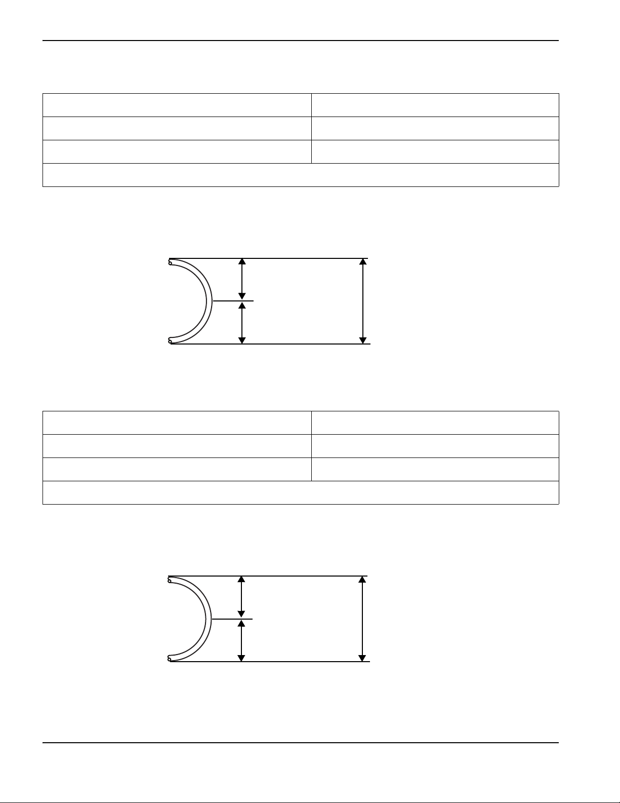
76 mm
(3.0 inches)
76 mm
(3.0 inches)
152 mm
(6.0 inches)
Diameter = 2 x Radius = 152 mm (6.0 inches)
10 2 m m
(4.0 inches)
10 2 m m
(4.0 inches)
204 mm
(8.0 inches)
Diameter = 2 x Radius = 204 mm (8.0 inches)
Duramax component weights
180° Duramax robotic torch with 7.6 m (25 foot) lead 3.3 kg (7.2 pounds)
90° Duramax robotic torch 7.6 m (25 foot) lead 3.3 kg (7.2 pounds)
45° Duramax robotic torch 7.6 m (25 foot) lead 3.3 kg (7.2 pounds)
Each Duramax robotic torch weighs 0.43 kg/m (0.29 pounds/foot).
The recommended minimum bend radius for the Duramax torch lead is 76 mm (3.0 inches). See Figure 1.
Figure 1 – Duramax bend radius
Duramax Hyamp component weights
180° Duramax Hyamp robotic torch with 7.6 m (25 foot) lead 3.5 kg (7.8 pounds)
90° Duramax Hyamp robotic torch 7.6 m (25 foot) lead 3.5 kg (7.8 pounds)
45° Duramax Hyamp robotic torch 7.6 m (25 foot) lead 3.5 kg (7.8 pounds)
Each Duramax Hyamp robotic torch weighs 0.46 kg/m (0.31 pounds/foot).
The recommended minimum bend radius for the Duramax Hyamp torch lead is 102 mm (4.0 inches). See Figure 2.
Figure2–Duramax Hyamp bend radius
16 Duramax/Duramax Hyamp Robotic Torches Service Manual 807460
Page 17
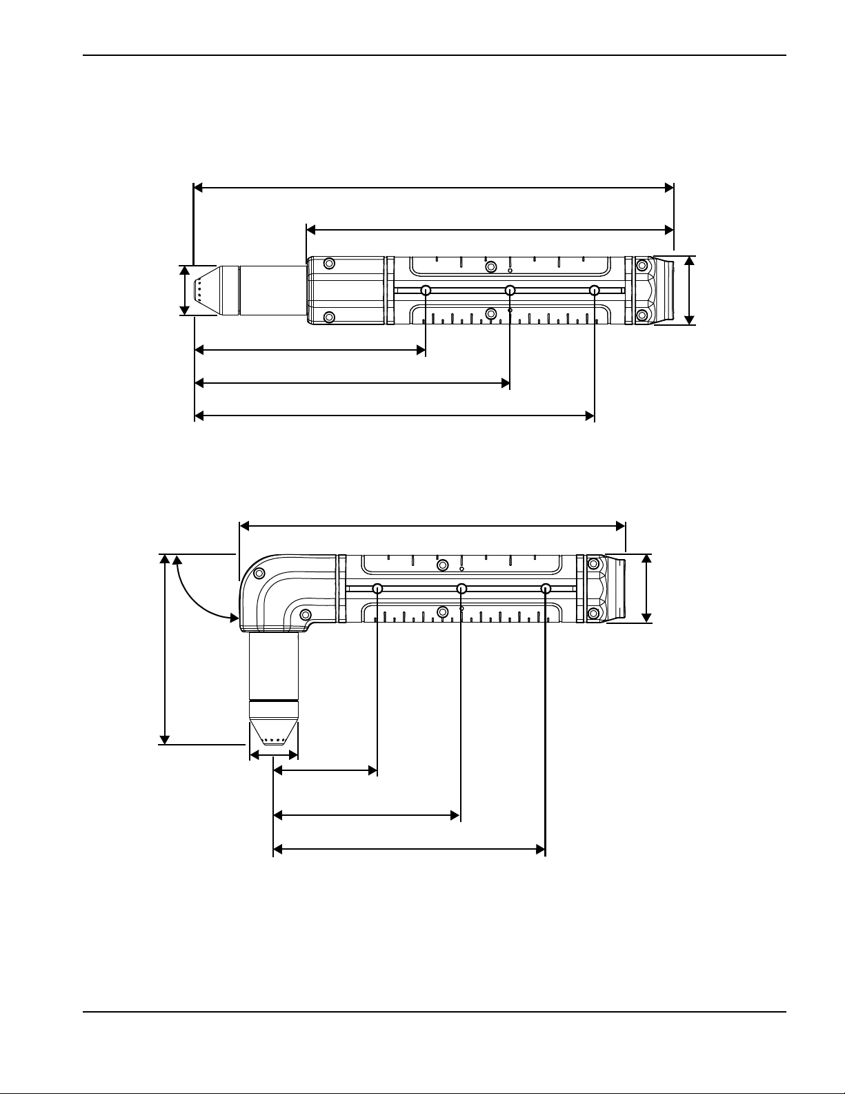
Torch dimensions
25.1 cm (9.89 inches)*
3.5 cm
(1.38 inches)
2.5 cm
(1.0 inch)
19.1 cm (7.50 inches)
12.2cm (4.82inches)*
16.6 cm (6.54 inches)*
21.0cm (8.27inches)*
14.2cm (5.58inches)*
20.1 cm (7.90 inches)
3.5 cm
(1.38 inches)
10 .1 c m
(3.97 inches)*
2.5 cm
(1.0 inch)
90°
5.41 cm
(2.13 inches)*
9.78 cm (3.85 inches)*
Duramax 180° robotic torch dimensions
1 – Specifications
Duramax 90° robotic torch dimensions
Duramax/Duramax Hyamp Robotic Torches Service Manual 807460 17
Page 18
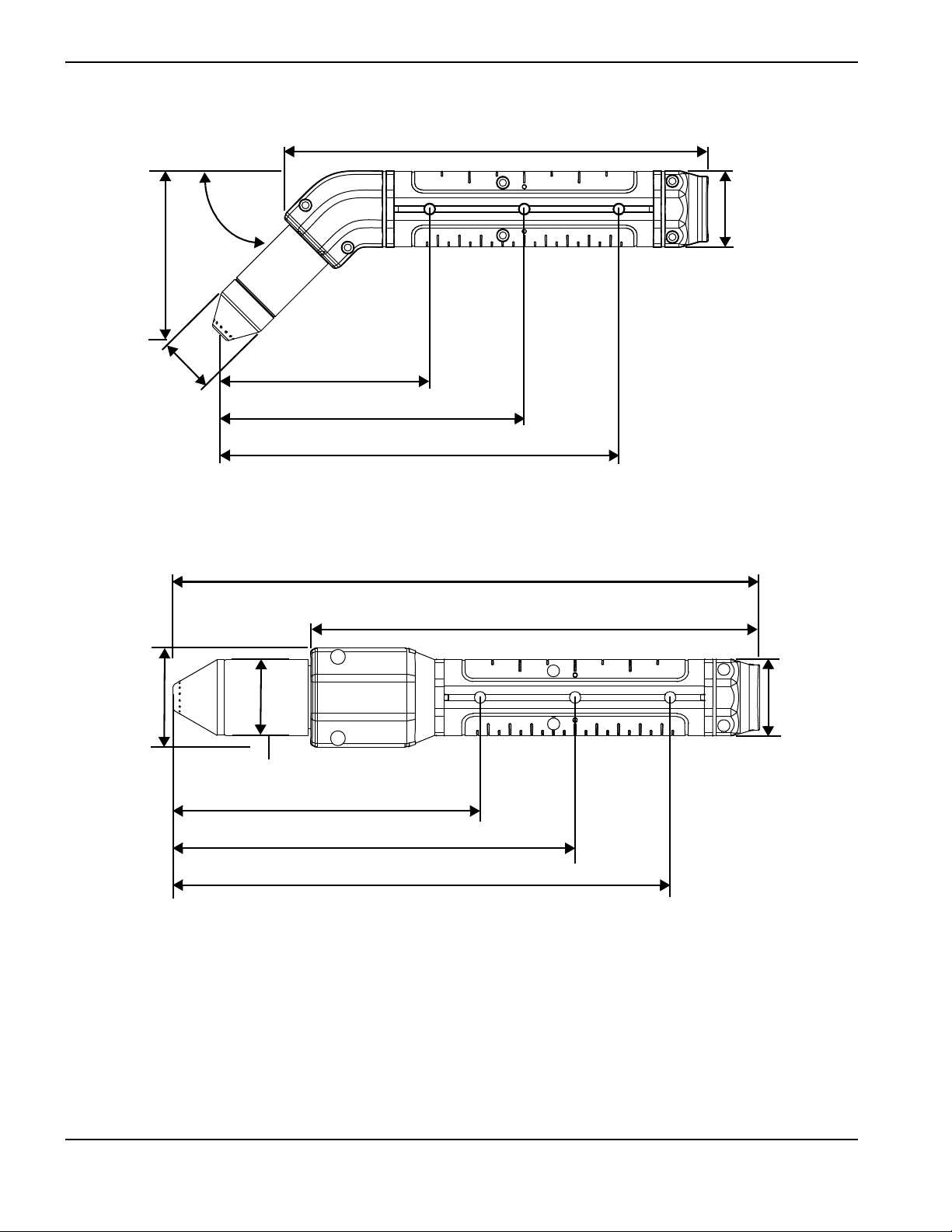
1 – Specifications
19.6 cm (7.72 inches)
3.51 cm
(1.38 inches)
8.0 cm
(3.15 inches)*
2.5 cm
(1.0 inch)
45°
9.88 cm (3.89 inches)*
14.3 cm (5.61 inches)*
18.6 cm (7.34 inches)*
27.1 cm (10.7 inches)*
3.5 cm
(1.38 inches)
3.5 cm
(1.38 inches)
20.8 cm (8.15 inches)
14.1 cm (5.57 inches)*
18.5 cm (7.30 inches)*
22.9cm (9.02inches)*
4.5 cm
(1.8 inches)
Duramax 45° robotic torch dimensions
Duramax Hyamp 180° robotic torch dimensions
18 Duramax/Duramax Hyamp Robotic Torches Service Manual 807460
Page 19
Duramax Hyamp 90° robotic torch dimensions
22.4 cm (8.80 inches)
3.5 cm
(1.38 inches)
12.2 cm
(4.79 inches)*
3.5 cm
(1.38 inches)
7.2cm (2.83inches)*
11.6 cm (4.55 inches)*
16.0cm (6.28inches)*
90°
21.8 cm (8.57 inches)
3.5 cm
(1.38 inches)
9.3 cm
(3.66 inches)*
3.5 cm
(1.38 inches)
45°
11.8 cm (4.66 inches)*
16.2cm (6.39inches)*
20.6 cm (8.11 inches)*
1 – Specifications
Duramax Hyamp 45° robotic torch dimensions
* Torch dimensions will vary depending on the type of consumables installed. The preceding figures show the mechanized shielded
consumables installed.
Duramax/Duramax Hyamp Robotic Torches Service Manual 807460 19
Page 20

1 – Specifications
20 Duramax/Duramax Hyamp Robotic Torches Service Manual 807460
Page 21
Robotic torch components
1 2 3 4
1 Consumables
2 Positioning barrel
3 Strain relief
4 Tor ch l ead
Duramax 180° is shown.
Section 2
Torch Setu p
Before using any robotic torch, you must:
Install and mount the torch.
Choose and install the consumables.
Attach the torch lead to the power supply.
Set up the power supply for remote starting with either the remote-start pendant or a machine interface cable.
Duramax/Duramax Hyamp Robotic Torches Service Manual 807460 21
Page 22
2 – Torch Setup
1
2
3
4
5
6
4.20 cm
(1.65 inches)
3.68 cm
(1.45 inches)
1 Disconnect button
2 Ta b
3 Top shell
4 Strain relief
5 Bottom shell
6 Mounting screws (4)
Install the torch
Depending on the type of torch, robot, and installation method, you may need to disassemble the FastConnect plug or
torch to install the torch. For the outside mounting method, it is not necessary to disassemble the torch. The torch can be
mounted per the instructions in Mount the torch on page 30.
For the through-arm mounting method, see Figure 3 to determine if the robot’s through-arm cavity is large enough to
accept the torch lead’s FastConnect plug as assembled or with the 2 shells removed. If the through-arm cavity is large
enough for the FastConnect plug as assembled, route the torch lead through the through-arm cavity. Then, mount the
torch to the robot arm per the instructions in Mount the torch on page 30.
Figure 3
22 Duramax/Duramax Hyamp Robotic Torches Service Manual 807460
Page 23
2 – Torch Setup
If the through-arm cavity is large enough for the disassembled FastConnect plug (see Figure 3 for dimensions), complete
the following instructions.
1. Remove the mounting screws from the bottom shell and pull the 2 shells apart.
The red disconnect button and tab on top of the FastConnect plug are spring loaded and
self-adjust below the surface of the plug while being routed through the through-arm
cavity.
2. Cover the end of the FastConnect plug with tape to keep dirt and other contaminants from getting into the gas line.
3. Route the torch lead through the through-arm cavity.
4. Install the 2 shells by aligning them over the torch lead, making sure the strain relief is held in place by the slot in the
FastConnect shells.
5. Tighten the mounting screws.
6. Mount the torch to the robot arm per the instructions in Mount the torch on page 30.
Disassemble the robotic torch
If the through-arm cavity is not large enough to accept the FastConnect plug at all (see Figure 3 for dimensions),
complete the following instructions to disassemble, install, and reassemble the torch.
WARNING!
ELECTRIC SHOCK CAN KILL
Disconnect electrical power before performing any maintenance.
The maintenance procedures in this section must be performed by a qualified
technician.
See the Safety and Compliance Manual (80669C) for more safety
precautions.
The instructions to disassemble and reassemble all 3 models of robotic torches are the same. The 45° robotic torch
is shown in the figures that follow.
Duramax/Duramax Hyamp Robotic Torches Service Manual 807460 23
Page 24

2 – Torch Setup
1
2
3
4
5
6
7
8
9
10
11
1 Right half of the positioning barrel
2 Cap-sensor switch connector
3 Cap-sensor switch
4 Pilot terminal screw
5 Torch body (torch head and gas tube)
6 Gas supply tube fitting
7 Gas fitting flange
8 Positioning barrel screws (6)
9 Left half of the positioning barrel
10 Tor ch le ad
11 Strain relief
Figure4–Duramax 45°
24 Duramax/Duramax Hyamp Robotic Torches Service Manual 807460
Figure 5 – Duramax Hyamp 45°
Page 25

2 – Torch Setup
2 3 41
1 Cap-sensor switch mounting post
2 Cap-sensor switch post hole
3 Gas fitting flange slot
4 Strain relief slot
1. Disconnect the torch lead from the power supply.
While disconnecting and reconnecting the torch parts, maintain the same orientation
between the torch body and torch lead. Twisting the torch body in relation to the torch
lead can cause damage.
2. Remove the consumables.
3. Place the torch on a flat surface with the left half of the positioning barrel facing up.
The left half of the positioning barrel is the side with the screws.
It may be helpful to clamp the lead in place to keep it from moving.
4. Remove the screws from the left half of the positioning barrel.
5. Lift the left half of the positioning barrel away from the torch.
6. The torch body fits snugly into the right half of the positioning barrel. While holding the torch body, gently press the
right half of the positioning barrel away from the torch body to remove it.
7. Slide the cap-sensor switch off its mounting post.
Figure6–Duramax 45° (top) and Duramax Hyamp 45° (bottom)
8. Remove the pilot terminal screw.
Duramax/Duramax Hyamp Robotic Torches Service Manual 807460 25
Page 26

2 – Torch Setup
9. Use 2 wrenches to loosen the gas fitting that secures the torch body to the torch lead.
Heating the gas fitting can help loosen the threadlocker and make removing the torch
body easier. Slowly heat only the fitting with a heat gun until you can easily loosen the
fitting.
CAUTION!
Do not apply heat to the wires. Heating the wires could cause damage to the connections in the torch
lead.
CAUTION!
Always use 2 wrenches to properly loosen and tighten the hex nuts and bolts mentioned in these
procedures. A strong threadlocker is used to assemble the torch, and loosening the nuts incorrectly
can damage the threads.
10. Cover the end of the gas line on the torch lead with tape to keep dirt and other contaminants from getting in the gas
line.
11 . Route the torch lead through the robot’s through-arm cavity.
12. Being careful not to get any threadlocker on the conical surface of the gas tube fitting, apply a drop of threadlocker,
included in the kit, to the threads of the gas tube fitting on the torch body.
The drop should not be wider than 2 threads in diameter.
CAUTION!
Do not get any threadlocker on the conical surface of the gas tube fitting to avoid causing damage
to the torch. If any threadlocker does get on this surface, clean it off immediately.
26 Duramax/Duramax Hyamp Robotic Torches Service Manual 807460
Page 27

13. Thread the torch body into the torch lead until snug.
Conical surface of the gas tube
fitting
The white wires of the lead should be facing up.
2 – Torch Setup
Figure 7
14. Use 2 wrenches to tighten the gas fitting that secures the torch body to the torch lead to 69.1 kg∙cm
(60 inch∙pounds).
15. Route the pilot arc wire under the gas tube and above the slot for the gas hose fitting’s flange. See Figure 8 and
Figure 9.
16. Tighten the pilot terminal screw to 17.3 kg∙cm (15 inch∙pounds).
The wire should go slightly down into the positioning barrel.
17. Press the cap-sensor switch into its post hole and onto its mounting post. (See Figure 6.)
18. Route the cap-sensor wires below the slot for the gas hose fitting’s flange.
Duramax/Duramax Hyamp Robotic Torches Service Manual 807460 27
Page 28

2 – Torch Setup
2
3
4
1
5
1 Pilot arc wire terminal
2 Cap-sensor switch
3 Cap-sensor switch connector
4 Gas fitting flange
5 Strain relief
2
3
4
1
5
1 Pilot arc wire terminal
2 Cap-sensor switch
3 Cap-sensor switch connector
4 Gas fitting flange
5 Strain relief
Figure8–Duramax wire routing
Figure9–Duramax Hyamp wire routing
19. Press the torch body into the right half of the positioning barrel with the gas fitting flange aligned with the slot in the
positioning barrel.
20. Align the strain relief with the strain relief slot in the positioning barrel.
21. Being careful that the positioning barrel and gas fitting flange do not pinch the wires, align the left half of the
positioning barrel with the right half.
22. Install the screws in the left half of the positioning barrel. Tighten to 15.0 kg∙cm (13.0 inch∙pounds).
28 Duramax/Duramax Hyamp Robotic Torches Service Manual 807460
Page 29

2 – Torch Setup
23. If the O-ring on the torch body is dry, lubricate it and the threads with a thin layer of silicone lubricant.
Silicone lubricant is included in several of the replacement kits.
24. Install the consumables.
25. Reconnect the torch and gas supply, and turn ON (I) the power.
Duramax/Duramax Hyamp Robotic Torches Service Manual 807460 29
Page 30

2 – Torch Setup
1
2
3
1 Increment markings
2 Anti-rotational slot
3 Positioning holes (3)
Mount the torch
Each style of robotic torch has 2 different mounting methods to maintain consistent positioning:
1. Increment markings – These are located on each side of the positioning barrel. One set is in inches and the other set
is in centimeters.
2. Positioning holes – These are equally spaced along the anti-rotational slots on each side of the barrel.
Figure 10
The robotic torch must be correctly mounted to the robot’s arm to make sure that there is proper torch-to-work distance
throughout each cut. A robotic torch clamp with mating positioning dowels and anti-rotational tabs is available from
Hypertherm. If you choose to use an alternate torch clamp, follow the manufacturer’s instructions on how to mount the
torch in the clamp. It is the customer’s responsibility to interface between the torch clamp and the robot’s arm.
30 Duramax/Duramax Hyamp Robotic Torches Service Manual 807460
Page 31

For the recommended minimum bend radius of the torch lead, see Figure 1 or Figure 2 on page 16.
0.76 cm
(0.30 inch)
1.91 cm
(0.75 inch)
2
1
1
2 11
1 0.45 cm (0.18 inch) through hole 2 M4 x 0.7 threaded hole
1
2
3
4
5
1 Positioning dowel
2 Rear half of the clamp
3 Front half of the clamp
4 Screws (4)
5 Anti-rotational tabs
If you are using Hypertherm’s robotic torch clamp (228806), complete the following instructions:
1. Mount the robotic torch clamp using one set of mounting holes (through hole or threaded).
Figure 11
2 – Torch Setup
2. Separate the torch clamp by removing the 4 screws from the front half of the torch clamp.
A second positioning dowel is provided in the kit to be used for additional mounting
support, if necessary, or as a replacement part.
Figure 12
Duramax/Duramax Hyamp Robotic Torches Service Manual 807460 31
Page 32

2 – Torch Setup
1
4
1
2
3
4
3. Align the torch with the clamp using either the increment markings or the positioning holes.
If you are using the increment markings, you must remove the positioning dowel from the
rear half of the torch clamp. Remove the dowel by pressing the end located in the center
hole of the torch clamp until it comes out.
4. Verify that the anti-rotational tabs on each half of the torch clamp are aligned with the slots in the torch.
5. Loosely hand tighten the 4 screws.
6. Starting with the upper left screw, step torque the 4 screws to 17.3 kg∙cm (15 inch∙pounds) in the pattern shown
below – .
Figure 13
32 Duramax/Duramax Hyamp Robotic Torches Service Manual 807460
Page 33

2 – Torch Setup
Consumable life
How often you need to change the consumables on your torch will depend on a number of factors:
The thickness of the metal being cut.
The average length of cut.
The air quality (presence of oil, moisture, or other contaminants).
Whether you are piercing the metal or starting cuts from the edge.
Proper torch-to-work distance when gouging or cutting with unshielded consumables.
Proper pierce height.
Whether you are cutting in “continuous pilot arc” mode or normal mode. Cutting with a continuous pilot arc causes
more consumable wear.
You will find more information about proper cutting techniques in Operation on page 47.
Duramax/Duramax Hyamp Robotic Torches Service Manual 807460 33
Page 34

2 – Torch Setup
220993
Shield
220854
Retaining cap
220990
Nozzle
220842
Electrode
220994
Swirl ring
220857
Swirl ring
220817
Shield
220854
Retaining cap
220816
Nozzle (85 A)
220842
Electrode
220819
Nozzle (65 A)
220941
Nozzle (45 A)
220948
Shield
220930
Nozzle
220842
Electrode
220994
Swirl ring
220854
Retaining cap
Choosing the consumables
Duramax robotic torches
Duramax robotic torches are shipped with a consumable kit that includes enough consumables to create a complete
consumable set for 65, 85, or 105 amperage shielded cutting. An ohmic-sensing retaining cap is available for use with
shielded consumables, a deflector is available for unshielded cutting and FineCut
fine-featured cutting on thin materials. All 3 styles of Duramax robotic torches use the same consumables.
With unshielded consumables, you must keep the torch a small distance, about 2.0 mm (0.08 inch), away
from the workpiece. Unshielded consumables generally have a shorter life than shielded consumables.
Duramax consumables
Duramax mechanized shielded 105 A*
®
consumables are available for
Duramax mechanized shielded 45 A, 65 A, 85 A*
Duramax FineCut shielded 105 A*
34 Duramax/Duramax Hyamp Robotic Torches Service Manual 807460
Page 35

Duramax FineCut shielded 65 A, 85 A*
220948
Shield
220930
Nozzle
220842
Electrode
220857
Swirl ring
220854
Retaining cap
220955
Deflector
220854
Retaining cap
220990
Nozzle
220842
Electrode
220994
Swirl ring
220955
Deflector
220854
Retaining cap
220816
Nozzle (85 A)
220842
Electrode
220857
Swirl ring
220819
Nozzle (65 A)
220941
Nozzle (45 A)
220955
Deflector
220854
Retaining cap
220930
Nozzle
220842
Electrode
220994
Swirl ring
*Ohmic-sensing retaining cap
You can use the ohmic-sensing retaining cap (220953) with the above consumable sets instead
of the standard retaining cap (220854).
Duramax mechanized unshielded 105 A
2 – Torch Setup
Duramax mechanized unshielded 45 A, 65 A, 85 A
Duramax FineCut unshielded 105 A
Duramax/Duramax Hyamp Robotic Torches Service Manual 807460 35
Page 36

2 – Torch Setup
220955
Deflector
220854
Retaining cap
220930
Nozzle
220842
Electrode
220857
Swirl ring
220798
Shield
220854
Retaining cap
220991
Nozzle
220842
Electrode
220994
Swirl ring
220798
Shield
220854
Retaining cap
220797
Nozzle
220842
Electrode
220857
Swirl ring
Duramax FineCut unshielded 65 A, 85
Duramax gouging 105 A
Duramax gouging 65 A, 85 A
36 Duramax/Duramax Hyamp Robotic Torches Service Manual 807460
Page 37

2 – Torch Setup
220976
Shield
220975
Nozzle
220971
Electrode
220997
Swirl ring
220977
Retaining cap
420168
Shield
220977
Retaining cap
420158 (45 A)
420169 (65 A)
Nozzle
220971
Electrode
220997
Swirl ring
420152
Shield
420151
Nozzle
220971
Electrode
220997
Swirl ring
220977
Retaining cap
420112
Shield
220977
Retaining cap
420001
Nozzle
220971
Electrode
220997
Swirl ring
Duramax Hyamp robotic torches
Duramax Hyamp robotic torches ship with a consumable kit that includes enough consumables to create a complete
consumable set for 45, 65, 105, or 125 amperage shielded cutting. Also notice that specific consumables are not
available for cutting at 85 A. Use the standard (drag-cutting) 105/125 A consumables to cut at 85 A. An ohmic-sensing
retaining cap is available for use with shielded consumables, and FineCut
®
consumables are available for fine-featured
cutting on thin materials. All 3 styles of Duramax Hyamp robotic torches use the same consumables.
Duramax Hyamp consumables
Duramax Hyamp mechanized shielded 105 A/125 A*
Duramax Hyamp mechanized shielded 45 A, 65 A*
Duramax Hyamp FineCut shielded*
*Ohmic-sensing retaining cap
You can use the ohmic-sensing retaining cap (420156) with the above consumable sets instead
of the standard retaining cap (220977).
Duramax Hyamp gouging
Duramax/Duramax Hyamp Robotic Torches Service Manual 807460 37
Page 38

2 – Torch Setup
1
2
3
4
5
1
2
3
4
5
Duramax Duramax Hyamp
1 Swirl ring
2 Electrode
3 Nozzle
4 Retaining cap
5 Shield
Installing the consumables
WARNING!
INSTANT-ON TORCHES
PLASMA ARC CAN CAUSE INJURY AND BURNS
The plasma arc comes on immediately when the torch trigger is activated. Make sure the
power is OFF before changing the consumables.
To operate the robotic torch, a complete set of consumable parts must be installed: shield, retaining cap, nozzle,
electrode, and swirl ring.
If the O-ring on the torch body is dry, lubricate it and the threads with a thin layer of silicone lubricant. Silicone lubricant is
included in several of the replacement kits. Then, to operate the torch, install the consumables as shown in Figure 14.
Make sure to use the appropriate parts to the corresponding system amperage. To replace the consumables, turn the
power switch to the OFF (O) position, remove the consumables, and install the new consumables by referring to
Figure 14.
Figure 14
38 Duramax/Duramax Hyamp Robotic Torches Service Manual 807460
Page 39

2 – Torch Setup
Red button
Connecting the torch lead
The Powermax65, Powermax85, Powermax105, and Powermax125 have FastConnect, a quick-disconnect system for
connecting and disconnecting hand, machine, and robotic torch leads. When connecting or disconnecting a torch, first
turn OFF the system. To connect the torch, push the connector into the receptacle on the front of the power supply.
Figure 15
To remove the torch, press the red button on the connector and pull the connector out of the receptacle.
Figure 16
Duramax/Duramax Hyamp Robotic Torches Service Manual 807460 39
Page 40

2 – Torch Setup
Receptacle for the remote-start
pendant or a machine interface cable.
Remote-start pendant
Connecting a remote-start pendant
An optional remote-start pendant is available for use with Powermax systems.
Part number 128650: 7.6 m (25 feet)
Part number 128651: 15 m (50 feet)
Part number 128652: 23 m (75 feet)
If your power supply has the machine interface receptacle on the rear of the power supply, remove the receptacle cover
and plug the Hypertherm remote-start pendant into the receptacle. If the system does not have a receptacle installed, a
CPC port upgrade kit (228697 for Powermax65/85) (228884 for Powermax105/125) is available from Hypertherm.
The remote-start pendant is for use only with a robotic or machine torch. It will not operate
if a hand torch is installed.
Figure 17
40 Duramax/Duramax Hyamp Robotic Torches Service Manual 807460
Page 41

2 – Torch Setup
Connecting the machine interface cable
The power supply may be equipped with a five-position voltage divider board. The built-in voltage divider provides a
scaled down arc voltage of 20:1, 21.1:1, 30:1, 40:1, or 50:1 (maximum output of 16 V). A receptacle on the rear of the
power supply (see Figure 17) provides access to the scaled down arc voltage and signals for arc transfer and plasma
start.
The factory presets the voltage divider to 50:1. To change the voltage divider to a different
setting, see Setting the five-position voltage divider on page 44.
CAUTION!
The factory-installed internal voltage divider provides a maximum of 16 V under open circuit
conditions. This is an impedance-protected functional extra low voltage (ELV) output to prevent
shock, energy, and fire under normal conditions at the machine interface receptacle and under single
fault conditions with the machine interface wiring. The voltage divider is not fault tolerant, and ELV
outputs do not comply with safety extra low voltage (SELV) requirements for direct connection to
computer products.
Hypertherm offers several choices of machine interface cables:
To use the built-in voltage divider that provides a scaled down arc voltage in addition to signals for arc transfer and
plasma start:
Use part number 228350 (7.6 m, 25 feet) or 228351 (15 m, 50 feet) for wires terminated with spade
connectors.
Use one of the following part numbers for a cable terminated with a D-sub connector. (Compatible with
Hypertherm products, such as EDGE
223354 (3.0 m, 10 feet)
223355 (6.1 m, 20 feet)
223048 (7.6 m, 25 feet)
223356 (10.7 m, 35 feet)
123896 (15 m, 50 feet)
To use signals for arc transfer and plasma start only, use either part number 023206 (7.6 m, 25 feet) or part
®
Pro Ti and Sensor™ PHC.)
number 023279 (15 m, 50 feet). These cables have spade connectors as follows:
Duramax/Duramax Hyamp Robotic Torches Service Manual 807460 41
Page 42

2 – Torch Setup
Refer to Machine interface pinout on page 43 for receptacle pinout information.
The cover on the machine interface receptacle prevents dust and moisture from damaging
the receptacle when not in use. This cover (127204) should be replaced if damaged or
lost.
Refer to Maintenance and Parts on page 65 for more information.
Installation of the machine interface cable must be performed by a qualified service technician. To install a machine
interface cable:
1. Turn OFF the power and disconnect the power cord.
2. Remove the machine interface receptacle’s cover from the rear of the power supply.
3. Connect the Hypertherm machine interface cable to the power supply.
4. If you are using a cable with a D-sub connector on the other end, plug it into the appropriate pin connector on the
torch height controller or CNC. Secure it with the screws on the D-sub connector.
If you are using a cable with wires and spade connectors on the other end, terminate the machine interface cable
inside the electrical enclosure of the torch height controller or CNC controller to prevent unauthorized access to the
connections after installation. Verify that the connections are correct and that all live parts are enclosed and
protected before operating the equipment.
The integration of Hypertherm equipment and customer-supplied equipment including
interconnecting cords and cables, if not listed and certified as a system, is subject to
inspection by local authorities at the final installation site.
The connector sockets for each type of signal available through the machine interface cable are shown in Figure 18.
Ta bl e 1 on page 43 provides details about each signal type.
42 Duramax/Duramax Hyamp Robotic Torches Service Manual 807460
Page 43

2 – Torch Setup
3
4
5
6
12
13
14
Machine interface pinout
Figure 18 – Connector sockets
Refer to Ta bl e 1 when connecting the power supply to a torch height controller or CNC controller with a machine
interface cable.
Table 1 – Machine interface cable signals
Signal Type Notes
Start (start plasma) Input Normally open.
18 VDC open circuit voltage at
START terminals. Requires dry
contact closure to activate.
Transfer (start machine
motion)
Ground Ground 13
Voltage divider Output Divided arc signal of 20:1, 21.1:1,
Output Normally open. Dry contact closure
when the arc transfers.
120 VAC/1 A maximum at the
machine interface relay.
30:1, 40:1, 50:1 (provides a
maximum of 16 V).
Connector
sockets
3, 4 Green, black
12, 14 Red, black
5(-), 6(+) Black (-), white (+)
External cable wires
Duramax/Duramax Hyamp Robotic Torches Service Manual 807460 43
Page 44

2 – Torch Setup
20:1 21.1:1 30:1 40:1 50:1
Setting the five-position voltage divider
To change the factory preset voltage divider from 50:1 to a different setting:
1. Turn OFF the power supply and disconnect the power cord.
2. Remove the power supply cover.
3. Locate the voltage divider DIP switches on the left side of the power supply.
Figure 19 shows the default setting (50:1) with the number 4 switch up.
Figure 19 – Voltage divider at default setting (50:1)
4. Set the DIP switches to one of the following settings, and replace the power supply cover.
If the Hypertherm five-position voltage divider does not supply the required voltage for your application, contact your
system integrator for assistance.
44 Duramax/Duramax Hyamp Robotic Torches Service Manual 807460
Page 45

2 – Torch Setup
Using the cut charts
The cut charts for each set of mechanized consumables can be found in the Tor ch Set up section of the Operator Manual
that shipped with the system. The manuals also can be downloaded from Hypertherm’s website (www.hypertherm.com
using the “Downloads library” link. A consumable diagram with part numbers precedes each set of charts. For each
consumable type, there are Metric and English charts for mild steel, stainless steel, and aluminum.
Each chart contains the following information:
Material Thickness – Thickness of the workpiece (metal plate being cut).
Torch-to-Work Distance – For shielded consumables, the distance between the shield and the workpiece during
cutting. For unshielded consumables, the distance between the nozzle and the workpiece during cutting.
Initial Pierce Height – Distance between the shield (shielded) or the nozzle (unshielded) and the workpiece when
the torch is triggered, prior to descending to the cut height.
Pierce Delay Time – Length of time the triggered torch remains stationary at the pierce height before the torch
starts the cutting motion.
Best Quality Settings (cut speed and voltage) – Settings that provide the starting point for finding the best cut
quality (best angle, least dross, best cut-surface finish). Adjust the speed for your application and table to obtain the
desired result.
)
Production Settings (cut speed and voltage) – 70% to 80% of the maximum speed ratings. These speeds result in
the greatest number of cut parts, but not necessarily the best possible cut quality.
The arc voltage increases as the consumables wear, so the voltage setting may need to
be increased to maintain the correct torch-to-work distance. Some CNCs monitor the arc
voltage and adjust the torch lifter automatically.
Each cut chart lists hot and cold air flow rates.
Hot air flow rate – Plasma is on, the system is operating at running current, and the system is in a steady state at
the default system pressure (automatic mode).
Cold air flow rate – Plasma is off and the system is in a steady state with air flowing through the torch at the default
system pressure.
Hypertherm collected the cut chart data under laboratory test conditions using new
consumables.
Duramax/Duramax Hyamp Robotic Torches Service Manual 807460 45
Page 46

2 – Torch Setup
46 Duramax/Duramax Hyamp Robotic Torches Service Manual 807460
Page 47

Section 3
Operation
Using the robotic torch
Since the robotic torch, combined with a Powermax system, can be used in a wide variety of applications, you will need to
refer to the robot manufacturer’s instructions for specifics on operating the robotic torch in your configuration. However,
the information in the following section will help you optimize cut quality and maximize consumable life.
Duramax/Duramax Hyamp Robotic Torches Service Manual 807460 47
Page 48

3 – Operation
Using the Duramax robotic teach tool
A robotic torch teach tool (229456) for only the Duramax robotic torches is available from Hypertherm to assist with
programming the robot before cutting. The torch teach tool enables the system operator to program the robot’s cutting
path, while visually verifying the torch will not touch the workpiece while cutting. Contact with the workpiece while cutting
can damage the shield and nozzle and affect the cut surface. The torch teach tool is equipped with a spring-loaded tip to
allow for variations in consumable lengths and stand-off distances.
To install the torch teach tool:
1. Tur n O FF (O) the power.
2. Remove the consumables from the torch.
3. Thread the torch teach tool onto the end of the torch
in place of the consumables.
As a safety feature, the torch teach tool does not engage
the cap-sensor switch. This will cause a cap-sensor fault
code to be generated when the system is turned ON,
thereby disabling the torch from firing while in teach
mode.
After programming the robot:
1. Tur n O FF (O) the power.
2. Remove the torch teach tool.
3. Install the consumables.
48 Duramax/Duramax Hyamp Robotic Torches Service Manual 807460
Page 49

3–Operation
Negative cut angle
Square cut
Positive cut angle
Problem Cause
The torch is too low.
The torch is too high.
Solution
Raise the torch; or if you are using a torch height
control, increase the arc voltage.
Lower the torch; or if you are using a torch height
control, decrease the arc voltage.
Understand and optimize cut quality
Several factors affect cut quality:
Cut angle – The degree of angularity of the cut edge.
Dross – The molten material that solidifies on the top or bottom of the workpiece.
Straightness of the cut surface – The cut surface can be concave or convex.
The following topics explain how these factors can affect cut quality.
Cut or bevel angle
A positive cut angle results when more material is removed from the top of the cut than from the bottom.
A negative cut angle results when more material is removed from the bottom of the cut.
Figure 20 – Cut angles
The squarest cut angle will be on the right side with respect to the forward motion of the
torch. The left side will always have some degree of cut angle.
To determine whether a cut-angle problem is being caused by the plasma system or the drive system, make a test cut and
measure the angle of each side. Next, turn the torch 90° in its holder and repeat the process. If the angles are the same in
both tests, the problem is in the drive system.
If a cut-angle problem persists after mechanical causes have been eliminated, check the torch-to-work distance,
especially if the cut angles are all positive or all negative. Also consider the material being cut: if the metal is magnetized
or hardened, you are more likely to experience cut angle problems.
Dross
Some amount of dross will always be present when cutting with air plasma. However, you can minimize the amount and
type of dross by adjusting your system correctly for your application.
Excess dross appears on the top edge of both pieces of the plate when the torch is too low (or voltage is too low when
using a torch height control). Adjust the torch or adjust the voltage in small increments (5 volts or less) until the dross is
reduced.
Duramax/Duramax Hyamp Robotic Torches Service Manual 807460 49
Page 50

3 – Operation
Low-speed dross forms when the torch’s cutting speed is too slow and the arc angles ahead. It forms as a heavy, bubbly
deposit at the bottom of the cut and can be removed easily. Increase the speed to reduce this type of dross.
High-speed dross forms when the cutting speed is too fast and the arc angles behind. It forms as a thin, linear bead of
solid metal attached very close to the cut. It is more firmly attached to the bottom of the cut than at low speed and is
difficult to remove. To reduce high-speed dross:
Decrease the cutting speed.
Decrease the torch-to-work distance.
Straightness of the cut surface
A typical plasma cut surface is slightly concave.
The cut surface may become more concave, or convex. Correct torch height is required to keep the cut
surface acceptably close to straight. Worn consumables also affect the straightness of the cut.
A strongly concave cut surface occurs when the torch-to-work distance is too low. Increase the
torch-to-work distance to straighten the cut surface.
A convex cut surface occurs when the torch-to-work distance is too great or the cutting current is too
high. First, try lowering the torch, then reduce the cutting current.
Piercing a workpiece using the robotic torch
As with the hand torch and machine torch, you can start a cut with the robotic torch at the edge of the workpiece or by
piercing the workpiece. Piercing may result in a shorter consumable life than with edge starts.
The cut charts, provided in the system’s Operator Manual, include a column for the recommended torch height when
starting a pierce. For the Powermax65, Powermax85, and Powermax105, the pierce height is generally 2.5 times the
cutting height. For the Powermax125, the pierce height is generally between 1.5 and 4 times the cut height. Refer to the
cut charts for specific values.
The pierce delay must be long enough that the arc can pierce the material before the torch moves, but not so long that
the arc “wanders” while trying to find the edge of a large hole. As consumables wear, this delay time may need to be
increased. Pierce delay times given in the cut charts are based on average delay times throughout the life of the
consumables.
When piercing materials close to the maximum thickness for a specific process, consider the following important factors:
Allow a lead-in distance approximately equal to the thickness of the material being pierced. For example, 20 mm
(0.75 inch) material requires a 20 mm lead-in.
To avoid damage to the shield from the buildup of molten material created by the pierce, do not allow the torch to
descend to cut height until it has cleared the puddle of molten material.
Different material chemistries can have an adverse effect on the pierce capability of the system. In particular,
high-strength steel with a high manganese or silicon content can reduce the maximum pierce capability. Hypertherm
calculates mild steel parameters with certified A-36 plate.
Using a “flying pierce” (that is, starting torch motion immediately after transfer and during the pierce process) can
extend the piercing capability of the system in some cases. Because this can be a complex process that can damage
the torch or other components, a stationary or edge start is recommended.
50 Duramax/Duramax Hyamp Robotic Torches Service Manual 807460
Page 51

3–Operation
Common machine-cutting faults
The torch’s pilot arc will initiate, but will not transfer.
The work lead is not making good contact with the cutting table, or the cutting table is not making good contact with
the workpiece.
The torch-to-work distance/cut height is too large.
The workpiece is not totally pierced, and there is excessive sparking on the top of the workpiece.
The metal surface is not clean of rust or paint.
The consumables are worn and need to be replaced. For optimized performance in a mechanized application, replace
the nozzle and the electrode together.
The work lead is not making good contact with the cutting table, or the cutting table is not making good contact with
the workpiece.
The current (amperage) is set too low. See the Torch S etu p section in the system’s Operator Manual for more
information.
The cut speed is too high. See the cut charts in the Torch Setup section of the system’s Operator Manual for more
information.
The metal being cut exceeds the maximum capacity for the selected amperage. See the Specifications section in the
system’s Operator Manual for more information.
Excessive dross forms on the bottom of the cut.
The gas setting is too high or too low.
The consumables are worn and need to be replaced. For optimized performance in a mechanized application, replace
the nozzle and the electrode together.
The cutting speed is not correct. See the cut charts in the Torch Set up section of the system’s Operator Manual for
more information.
The current (amperage) is set too low. See the cut charts in the Tor ch Set up section of the system’s Operator Manual
for more information.
The cut angle is not square.
The torch is not square to the workpiece.
The gas setting is incorrect.
The consumables are worn and need to be replaced. For optimized performance in a mechanized application, replace
the nozzle and the electrode together.
The direction of the torch travel is incorrect. The high-quality cut is always on the right with respect to the forward
motion of the torch.
The torch-to-work distance/cut height is too large or too small.
The cutting speed is not correct. See the cut charts in the Torch Set up section of the system’s Operator Manual for
more information.
The consumable life is shortened.
The gas setting is incorrect.
The arc current, arc voltage, travel speed, and other variables are not set as recommended in the cut charts.
Duramax/Duramax Hyamp Robotic Torches Service Manual 807460 51
Page 52

3 – Operation
The torch is fired into the air (beginning or ending the cut off of the plate surface). Starting at the edge is acceptable
as long as the arc makes contact with the workpiece when started.
A pierce is started with an incorrect torch height. See the cut charts in the Tor ch Setu p section of the system’s
Operator Manual for the specific initial pierce height.
The pierce time is incorrect.
The air quality is poor (oil or water in the air).
There might be a faulty pilot arc IGBT, which can shorten nozzle life.
The swirl ring or retaining cap is worn and needs to be replaced.
52 Duramax/Duramax Hyamp Robotic Torches Service Manual 807460
Page 53

Component Replacement
WARNING!
ELECTRIC SHOCK CAN KILL
Disconnect electrical power before performing any maintenance.
The maintenance procedures in this section must be performed by a qualified
technician.
See the Safety and Compliance Manual (80669C) for more safety
precautions.
Duramax and Duramax Hyamp robotic torch overview
Section 4
The instructions to replace components in all 6 models of robotic torches (180°, 90°, and 45°) are very similar. Any
differences are noted in the steps. The 45° Duramax and Duramax Hyamp robotic torches are shown in the figures that
follow.
While disconnecting and reconnecting the torch parts, maintain the same orientation
between the torch body and torch lead. Twisting the torch body in relation to the torch
lead can cause damage.
Duramax/Duramax Hyamp Robotic Torches Service Manual 807460 53
Page 54

4 – Component Replacement
2
3
4
5
6
7
8
9
10
11
1
1 Right half of the positioning barrel
2 Cap-sensor switch connector
3 Cap-sensor switch
4 Pilot terminal screw
5 Torch body (torch head and gas tube)
6 Gas supply tube fitting
7 Gas fitting flange
8 Positioning barrel screws (6)
9 Left half of the positioning barrel
10 Tor ch le ad
11 Strain relief
1
2
3
4
5
6
7
8
9
10
11
1 Right half of the positioning barrel
2 Cap-sensor switch connector
3 Cap-sensor switch
4 Pilot terminal screw
5 Torch body (torch head and gas tube)
6 Gas supply tube fitting
7 Gas fitting flange
8 Positioning barrel screws (6)
9 Left half of the positioning barrel
10 Tor ch le ad
11 Strain relief
Figure 21 – Duramax 45°
54 Duramax/Duramax Hyamp Robotic Torches Service Manual 807460
Figure 22 – Duramax Hyamp 45°
Page 55

Disconnect the power, gas supply, and torch
1
3
4
2
1. Turn the plasma power supply switch to OFF (O).
2. Turn the line disconnect switch to OFF (O).
3. Disconnect the gas supply hose from the plasma power supply.
4. Disconnect the torch from the plasma power supply.
Figure 23
4 – Component Replacement
Duramax/Duramax Hyamp Robotic Torches Service Manual 807460 55
Page 56

4 – Component Replacement
Replacing the positioning barrel
Kit Description
228856 Kit: Duramax 180° robotic torch positioning barrel replacement
228857 Kit: Duramax 90° robotic torch positioning barrel replacement
228858 Kit: Duramax 45° robotic torch positioning barrel replacement
428295 Kit: Duramax Hyamp 180° robotic torch barrel replacement
428294 Kit: Duramax Hyamp 90° robotic torch barrel replacement
428293 Kit: Duramax Hyamp 45° robotic torch barrel replacement
Remove the positioning barrel
1. Tur n O FF (O) the power, disconnect the gas supply, and disconnect the torch.
2. Remove the consumables from the torch.
3. Place the torch on a flat surface with the left half of the positioning barrel facing up.
The left half of the positioning barrel is the side with the screws.
It may be helpful to clamp the lead in place to keep it from moving.
4. Remove the screws from the left half of the positioning barrel.
5. Lift the left half of the positioning barrel away from the torch.
6. The torch body fits snugly into the right half of the positioning barrel. While holding the torch body, gently press the
right half of the positioning barrel away from the torch body to remove it.
7. Slide the cap-sensor switch off its mounting post.
56 Duramax/Duramax Hyamp Robotic Torches Service Manual 807460
Page 57

4 – Component Replacement
2
3
4
1
1 Cap-sensor switch mounting post
2 Cap-sensor switch post hole
3 Gas fitting flange slot
4 Strain relief slot
Figure 24 – Duramax 45° (top) and Duramax Hyamp 45° (bottom)
Install the positioning barrel
1. Lay the right half of the positioning barrel on a flat surface with the inside facing up.
If replacing the positioning barrel, use the new barrel halves included in the kit.
2. Press the cap-sensor switch into its post hole and onto its mounting post. (See Figure 24.)
3. Route the cap-sensor wires below the slot for the gas hose fitting’s flange.
4. Route the pilot arc wire under the gas tube and above the slot for the gas hose fitting’s flange. (See Figure 25 and
Figure 26.)
Duramax/Duramax Hyamp Robotic Torches Service Manual 807460 57
Page 58

4 – Component Replacement
2
3
4
1
5
1 Pilot arc wire terminal
2 Cap-sensor switch
3 Cap-sensor switch connector
4 Gas fitting flange
5 Strain relief slot
2
3
4
1
5
1 Pilot arc wire terminal
2 Cap-sensor switch
3 Cap-sensor switch connector
4 Gas fitting flange
5 Strain relief slot
Figure 25 – Duramax wire routing
Figure 26 – Duramax Hyamp wire routing
5. Press the torch body into the right half of the positioning barrel with the gas fitting flange aligned with the slot in the
positioning barrel.
6. Align the strain relief with the strain relief slot in the positioning barrel.
7. Being careful that the positioning barrel and gas fitting flange do not pinch the wires, align the left half of the
positioning barrel with the right half.
8. Install the screws in the left half of the positioning barrel. Tighten to 15.0 kg∙cm (13.0 inch∙pounds).
58 Duramax/Duramax Hyamp Robotic Torches Service Manual 807460
Page 59

4 – Component Replacement
9. If the O-ring on the torch body is dry, lubricate it and the threads with a thin layer of silicone lubricant.
Silicone lubricant is included in several of the replacement kits.
10. Install the consumables.
11 . Reconnect the torch and gas supply, and turn ON (I) the power.
Replacing the torch body
Kit Description
228853 Kit: Duramax 180° robotic torch main body replacement
228854 Kit: Duramax 90° robotic torch main body replacement
228855 Kit: Duramax 45° robotic torch main body replacement
428298 Kit: Duramax Hyamp 180° robotic torch main body replacement
428297 Kit: Duramax Hyamp 90° robotic torch main body replacement
428296 Kit: Duramax Hyamp 45° robotic torch main body replacement
1. Complete the following procedures:
a. See Disconnect the power, gas supply, and torch on page 55.
b. Remove all components from the torch. See Remove the positioning barrel on page 56.
2. Remove the pilot terminal screw.
3. Use 2 wrenches to loosen the gas fitting that secures the torch body to the torch lead.
Heating the gas fitting can help loosen the threadlocker and make removing the torch
body easier. Slowly heat only the fitting with a heat gun until you can easily loosen the
fitting.
CAUTION!
Do not apply heat to the wires. Heating the wires could cause damage to the connections in the torch
lead.
CAUTION!
Always use 2 wrenches to properly loosen and tighten the hex nuts and bolts mentioned in these
procedures. A strong threadlocker is used to assemble the torch, and loosening the nuts incorrectly
can damage the threads.
Duramax/Duramax Hyamp Robotic Torches Service Manual 807460 59
Page 60

4 – Component Replacement
Conical surface of the gas tube
fitting
4. Being careful not to get any threadlocker on the conical surface of the gas tube fitting, apply a drop of threadlocker,
included in the kit, to the threads of the gas tube fitting on the torch body.
The drop should not be wider than 2 threads in diameter.
CAUTION!
Do not get any threadlocker on the conical surface of the gas tube fitting to avoid causing damage
to the torch. If any threadlocker does get on this surface, clean it off immediately.
Figure 27
5. Thread the torch body into the torch lead until snug.
The white wires of the lead should be facing up.
6. Use 2 wrenches to tighten the gas fitting that secures the torch body to the torch lead to 69.1 kg∙cm
(60 inch∙pounds).
7. Route the pilot arc wire under the gas tube and above the slot for the gas hose fitting’s flange. (See Figure 25 and
Figure 26.)
8. Tighten the pilot terminal screw to 17.3 kg∙cm (15 inch∙pounds).
The wire should go slightly down into the positioning barrel.
9. Complete the following procedures:
a. Install all of the torch components that you removed. See Install the positioning barrel on page 57.
b. Reconnect the torch and gas supply, and turn ON (I) the power.
60 Duramax/Duramax Hyamp Robotic Torches Service Manual 807460
Page 61

4 – Component Replacement
Ta b
Cap-sensor switch
Replacing the cap-sensor switch
Kit Description
228109 Kit: Cap-sensor switch replacement
1. Complete the following procedures:
a. See Disconnect the power, gas supply, and torch on page 55.
b. Remove all components from the torch. See Remove the positioning barrel on page 56.
2. Disconnect the cap-sensor switch by pressing the tab on the connector and pulling the connector apart.
Figure 28
3. Connect the new cap-sensor switch to the torch lead by pushing the mating plug on the torch lead wires into the
socket.
4. Complete the following procedures:
a. Install all of the torch components that you removed. See Install the positioning barrel on page 57.
b. Reconnect the torch and gas supply, and turn ON (I) the power.
Duramax/Duramax Hyamp Robotic Torches Service Manual 807460 61
Page 62

4 – Component Replacement
Ta b
Cap-sensor switch
Replacing the torch lead
Kit Description
228852 Kit: Robotic torch lead replacement, 7.6 m (25 feet)
428292 Kit: Duramax Hyamp robotic torch lead replacement, 7.6 m (25 feet)
1. Complete the following procedures:
a. See Disconnect the power, gas supply, and torch on page 55.
b. Remove all components from the torch. See Remove the positioning barrel on page 56.
2. Disconnect the cap-sensor switch.
Figure 29
3. Remove the pilot terminal screw.
4. Use 2 wrenches to loosen the gas fitting that secures the torch body to the torch lead.
Heating the gas fitting can help loosen the threadlocker and make removing the torch
body easier. Slowly heat only the fitting with a heat gun until you can easily loosen the
fitting.
CAUTION!
Do not apply heat to the wires. Heating the wires could cause damage to the connections in the torch
lead.
CAUTION!
Always use 2 wrenches to properly loosen and tighten the hex nuts and bolts mentioned in these
procedures. A strong threadlocker is used to assemble the torch, and loosening the nuts incorrectly
can damage the threads.
62 Duramax/Duramax Hyamp Robotic Torches Service Manual 807460
Page 63

4 – Component Replacement
Conical surface of the gas tube
fitting
5. Being careful not to get any threadlocker on the conical surface of the gas tube fitting, apply a drop of threadlocker,
included in the kit, to the threads of the gas tube fitting on the torch body.
The drop should not be wider than 2 threads in diameter.
CAUTION!
Do not get any threadlocker on the conical surface of the gas tube fitting to avoid causing damage
to the torch. If any threadlocker does get on this surface, clean it off immediately.
Figure 30
6. Thread the torch body into the torch lead until snug.
The white wires of the lead should be facing up.
7. Use 2 wrenches to tighten the gas fitting that secures the torch body to the torch lead to 69.1 kg∙cm
(60 inch∙pounds).
8. Route the pilot arc wire under the gas tube. (See Figure 25 and Figure 26.)
9. Tighten the pilot terminal screw to 17.3 kg∙cm (15 inch∙pounds).
The wire should go slightly down into the positioning barrel.
10. Connect the cap-sensor switch.
Duramax/Duramax Hyamp Robotic Torches Service Manual 807460 63
Page 64

4 – Component Replacement
Ta b
Cap-sensor switch
Figure 31
11 . Complete the following procedures:
a. Install all of the components that you removed. See Install the positioning barrel on page 57.
b. Reconnect the torch and gas supply, and turn ON (I) the power.
64 Duramax/Duramax Hyamp Robotic Torches Service Manual 807460
Page 65

Perform routine maintenance
Disconnect electrical power before performing any maintenance.
See the Safety and Compliance Manual (80669C) for more safety
precautions.
Section 5
Maintenance and Parts
WARNING!
ELECTRIC SHOCK CAN KILL
Duramax/Duramax Hyamp Robotic Torches Service Manual 807460 65
Page 66

5 – Maintenance and Parts
AC
Routine maintenance tasks
Every use:
Check indicator lights and fault icons.
Correct any fault conditions.
Every 3 months:
Inspect the consumables for proper
installation and wear.
Replace any damaged labels.
Inspect the power cord and plug. Replace if
damaged.
Every 6 months:
Inspect the torch lead. Replace if
damaged.
or Clean the inside of the power supply
with moisture-free compressed air
or a vacuum.
66 Duramax/Duramax Hyamp Robotic Torches Service Manual 807460
Page 67

Inspect the consumables
Max. 1.6mm (1/16inch)
Part Inspect Action
The center hole for roundness. Replace the shield if the hole is no longer
5 – Maintenance and Parts
round.
Shield
Nozzle
Electrode
The gap between the shield and the
nozzle for accumulated debris.
The center hole for roundness. Replace the nozzle if the center hole is not
The surface inside the swirl ring for
damage or wear and the gas holes for
blockages.
The O-ring for damage or wear. If the O-ring is worn or damaged, replace it.
Remove the shield and clean away any
material.
round.
Replace the nozzle and the electrode
together.
Replace the electrode if the surface is worn
or the pit depth is greater than 1.6 mm
(1/16 inch) deep.
Replace the nozzle and electrode together.
Replace the swirl ring if the surface is
damaged or worn or any of the gas holes
are blocked.
(See Duramax robotic torch replacement
parts on page 68 or Duramax Hyamp
robotic torch replacement parts on
page 71.)
Swirl ring
Torch O-ring
The length of the swirl ring. Duramax Hyamp: If the length of the
220997 swirl ring is less than 32 mm
(1.27 inches), replace it.
Duramax: If the length of the 220994 or
220857 swirl ring is less than 30.5 mm
(1.20 inches), replace it.
The surface for damage, wear, or a lack
of lubrication.
If the O-ring is dry, lubricate it and the
threads with a thin layer of silicone lubricant.
If the O-ring is worn or damaged, replace it.
(See Duramax robotic torch replacement
parts on page 68.)
Duramax/Duramax Hyamp Robotic Torches Service Manual 807460 67
Page 68

5 – Maintenance and Parts
1
2
3
4
6
7
5
1
Duramax robotic torch replacement parts
Duramax 180° robotic torch
The entire Duramax 180° robotic torch assembly with leads can be replaced, or individual component parts can be
replaced.
Part Number Description
059466 Duramax 180° robotic torch assembly with leads, 7.6 m (25 feet)
1
228856 Kit: Duramax 180° robotic torch positioning barrel replacement
2
228853 Kit: Duramax 180° robotic torch main body replacement
3
058519 O-ring
4
075714 Positioning barrel screws
5
428260 Kit: FastConnect replacement
6
228852 Kit: Robotic torch lead replacement, 7.6 m (25 feet)
7
228109 Kit: Cap-sensor switch replacement
68 Duramax/Duramax Hyamp Robotic Torches Service Manual 807460
Page 69

5 – Maintenance and Parts
1
2
3
4
6
7
5
1
Duramax 90° robotic torch
The entire Duramax 90° robotic torch assembly with leads can be replaced, or individual component parts can be
replaced.
Part Number Description
059465 90° Duramax robotic torch assembly with leads, 7.6 m (25 feet)
1
228857 Kit: Duramax 90° robotic torch positioning barrel replacement
2
228854 Kit: Duramax 90° robotic torch main body replacement
3
058519 O-ring
4
075714 Positioning barrel screws
5
428260 Kit: FastConnect replacement
6
228852 Kit: Robotic torch lead replacement, 7.6 m (25 feet)
7
228109 Kit: Cap-sensor switch replacement
Duramax/Duramax Hyamp Robotic Torches Service Manual 807460 69
Page 70

5 – Maintenance and Parts
1
2
3
4
6
7
5
1
Duramax 45° robotic torch
The entire Duramax 45° robotic torch assembly with leads can be replaced, or individual component parts can be
replaced.
Part Number Description
059464 Duramax 45° robotic torch assembly with leads, 7.6 m (25 feet)
1
228858 Kit: Duramax 45° robotic torch positioning barrel replacement
2
228855 Kit: Duramax 45° robotic torch main body replacement
3
058519 O-ring
4
075714 Positioning barrel screws
5
428260 Kit: FastConnect replacement
6
228852 Kit: Robotic torch lead replacement, 7.6 m (25 feet)
7
228109 Kit: Cap-sensor switch replacement
70 Duramax/Duramax Hyamp Robotic Torches Service Manual 807460
Page 71

Duramax Hyamp robotic torch replacement parts
1
2
3
6
7
5
1
4
Duramax Hyamp 180° robotic torch
5 – Maintenance and Parts
The entire Duramax Hyamp 180° robotic torch assembly with leads can be replaced, or individual component parts can
be replaced.
Part Number Description
059566 Duramax Hyamp 180° robotic torch assembly with leads, 7.6 m (25 feet)
1
428295 Kit: Duramax Hyamp 180° robotic torch barrel replacement
2
428298 Kit: Duramax Hyamp 180° robotic torch main body replacement
3
428253 O-ring (5)
4
075714 Positioning barrel screws
5
428260 Kit: FastConnect replacement
6
428292 Kit: Duramax Hyamp robotic torch lead replacement, 7.6 m (25 feet)
7
228109 Kit: Cap-sensor switch replacement
Duramax/Duramax Hyamp Robotic Torches Service Manual 807460 71
Page 72

5 – Maintenance and Parts
1
2
3
6
7
5
1
4
Duramax Hyamp 90° robotic torch
The entire Duramax Hyamp 90° robotic torch assembly with leads can be replaced, or individual component parts can be
replaced.
Part Number Description
059565 Duramax Hyamp 90° robotic torch assembly with leads, 7.6 m (25 feet)
1
428294 Kit: Duramax Hyamp 90° robotic torch barrel replacement
2
428297 Kit: Duramax Hyamp 90° robotic torch main body replacement
3
428253 O-ring (5)
4
075714 Positioning barrel screws
5
428260 Kit: FastConnect replacement
6
428292 Kit: Duramax Hyamp robotic torch lead replacement, 7.6 m (25 feet)
7
228109 Kit: Cap-sensor switch replacement
72 Duramax/Duramax Hyamp Robotic Torches Service Manual 807460
Page 73

Duramax Hyamp 45° robotic torch
1
2
3
6
7
5
1
4
5 – Maintenance and Parts
The entire Duramax Hyamp 45° robotic torch assembly with leads can be replaced, or individual component parts can be
replaced.
Part Number Description
059564 Duramax Hyamp 45° robotic torch assembly with leads, 7.6 m (25 feet)
1
428293 Kit: Duramax Hyamp 45° robotic torch barrel replacement
2
428296 Kit: Duramax Hyamp 45° robotic torch main body replacement
3
428253 O-ring (5)
4
075714 Positioning barrel screws
5
428260 Kit: FastConnect replacement
6
428292 Kit: Duramax Hyamp robotic torch lead replacement, 7.6 m (25 feet)
7
228109 Kit: Cap-sensor switch replacement
Duramax/Duramax Hyamp Robotic Torches Service Manual 807460 73
Page 74

5 – Maintenance and Parts
Accessory parts
Part Number Description
024548 Brown leather torch sheathing, 7.6 m (25 feet)
024877 Black leather torch sheathing with Hypertherm logo, 7.6 m (25 feet)
228806 Kit: Robotic clamp torch assembly
229456 Duramax robotic torch teach assembly
74 Duramax/Duramax Hyamp Robotic Torches Service Manual 807460
 Loading...