

Command®THC
X-Y Table
Torch Height Control
(THC) System
Instruction Manual
802780 – Revision 11
EN50199
EN60974-1

Register your new Hypertherm system
Register your product on-line at www.hypertherm.com/registration for easier technical
and warranty support. You can also receive updates on new Hypertherm products and a
free gift as a token of our appreciation.
For your records
Serial number: ______________________________________________________
Purchase date: ______________________________________________________
Distributor: ______________________________________________________
___________________________________________________________________
___________________________________________________________________
Maintenance notes:
________________________________________________________________________
________________________________________________________________________
________________________________________________________________________
________________________________________________________________________
________________________________________________________________________
________________________________________________________________________

Instruction Manual
(P/N 802780)
Revision 11 – February 2009
© Copyright 2009 Hypertherm, Inc.
All Rights Reserved
Hypertherm, HyPerformance, HPR, HSD and CommandTHC are trademarks of Hypertherm, Inc.,
and may be registered in the United States and/or other countries
Command®THC
X-Y Table
Torch Height Control
(THC) System
Hypertherm, Inc.
Hanover, NH USA
www.hypertherm.com

10/14/08
Hypertherm, Inc.
Etna Road, P.O. Box 5010
Hanover, NH 03755 USA
603-643-3441 Tel (Main Office)
603-643-5352 Fax (All Departments)
info@hypertherm.com (Main Office Email)
800-643-9878 Tel (Technical Service)
technical.service@hypertherm.com (Technical Service Email)
800-737-2978 Tel (Customer Service)
customer.service@hypertherm.com (Customer Service Email)
Hypertherm Automation
5 Technology Drive, Suite 300
West Lebanon, NH 03784 USA
603-298-7970 Tel
603-298-7977 Fax
Hypertherm Plasmatechnik GmbH
Technologiepark Hanau
Rodenbacher Chaussee 6
D-63457 Hanau-Wolfgang, Deutschland
49 6181 58 2100 Tel
49 6181 58 2134 Fax
49 6181 58 2123 (Technical Service)
Hypertherm (S) Pte Ltd.
82 Genting Lane
Media Centre
Annexe Block #A01-01
Singapore 349567, Republic of Singapore
65 6841 2489 Tel
65 6841 2490 Fax
65 6841 2489 (Technical Service)
Hypertherm (Shanghai) Trading Co., Ltd.
Unit A, 5th Floor, Careri Building
432 West Huai Hai Road
Shanghai, 200052
PR China
86-21 5258 3330/1 Tel
86-21 5258 3332 Fax
Hypertherm Europe B.V.
Vaartveld 9
4704 SE
Roosendaal, Nederland
31 165 596907 Tel
31 165 596901 Fax
31 165 596908 Tel (Marketing)
31 165 596900 Tel (Technical Service)
00 800 4973 7843 Tel (Technical Service)
Hypertherm Japan Ltd.
801 Samty Will Building
2-40 Miyahara 1-Chome,
Yodogawa-ku, Osaka
532-0003, Japan
81 6 6170 2020 Tel
81 6 6170 2015 Fax
HYPERTHERM BRASIL LTDA.
Avenida Doutor Renato de
Andrade Maia 350
Parque Renato Maia
CEP 07114-000
Guarulhos, SP Brasil
55 11 2409 2636 Tel
55 11 2408 0462 Fax

ELECTROMAGNETIC COMPATIBILITY (EMC)
Hypertherm i
4-08
EMC Introduction
Hypertherm’s CE-marked equipment is built in compliance
with standard EN60974-10. The equipment should be
installed and used in ac cor dance with the information
below to achieve elec tro mag net ic compatibility.
The limits required by EN60974-10 may not be adequate
to com plete ly eliminate in ter fer ence when the affected
equip ment is in close proximity or has a high degree of
sensitivity. In such cases it may be nec es sary to use other
mea s ures to fur ther reduce interference.
This cutting equipment is designed for use only in an
indus tri al environment.
Installation and use
The user is responsible for installing and using the plasma
equipment according to the manufacturer’s instructions.
If elec tro mag net ic disturbances are detected then it shall
be the re spon si bil i ty of the user to re solve the situation
with the technical as sis tance of the man u fac tur er. In some
cases this remedial action may be as sim ple as earthing
the cutting circuit, see Earthing of Workpiece. In other
cas es it could in volve con struct ing an elec tro mag net ic
screen enclosing the pow er source and the work
complete with associated input filters. In all cases
electromag net ic dis tur banc es must be reduced to the
point where they are no longer trou ble some.
Assessment of area
Before installing the equipment the user shall make an
assessment of po ten tial elec tro mag net ic problems in the
sur round ing area. The following shall be taken into
account:
a. Other supply cables, control cables, signalling and
telephone ca bles; above, below and adjacent to the
cutting equip ment.
b. Radio and television transmitters and receivers.
c. Computer and other control equip ment.
d. Safety critical equipment, for example guarding of
industrial equipment.
e. Health of the people around, for example the use of
pacemakers and hear ing aids.
f. Equipment used for calibration or mea sure ment.
g. Immunity of other equipment in the en viron ment. User
shall ensure that other equip ment being used in the
environment is com pat i ble. This may require ad di tion al
protection measures.
h. Time of day that cutting or other ac tiv i ties are to be
carried out.
The size of the sur round ing area to be considered will
depend on the structure of the building and other
activities that are tak ing place. The surrounding area may
ex tend beyond the bound aries of the pre mises.
Methods of reducing emissions
Mains supply
Cutting equipment must be con nect ed to the mains
supply according to the man u fac tur er’s recommendations.
If interfer ence occurs, it may be necessary to take
additional precautions such as filtering of the mains supply.
Consideration should be given to shield ing the supply
cable of per ma nent ly installed cutting equip ment, in
metallic conduit or equiva lent. Shield ing should be
electrical ly continuous through out its length. The shielding
should be connected to the cutting mains supply so that
good electrical contact is maintained between the conduit
and the cutting pow er source enclosure.
Maintenance of cutting equipment
The cutting equipment must be rou tine ly main tained
according to the man u fac tur er’s rec om men da tions. All
access and service doors and covers should be closed
and properly fastened when the cutting equipment is in
op er a tion. The cutting equipment should not be modified
in any way except for those chang es and adjust ments
covered in the manufacturer’s instructions. In par tic u lar,
the spark gaps of arc striking and stabilizing devices
should be adjusted and maintained according to the
manufacturer’s rec om men da tions.
Cutting cables
The cutting cables should be kept as short as possible
and should be po si tioned close together, running at or
close to the floor level.
Equipotential bonding
Bonding of all metallic components in the cutting
installation and adjacent to it should be considered.
However, metallic com po nents bonded to the workpiece
will increase the risk that the op er a tor could receive a
shock by touch ing these metallic compo nents and the
electrode (nozzle for laser heads) at the same time.
The op er a tor should be in su lat ed from all such bonded
metallic components.

ELECTROMAGNETIC COMPATIBILITY (EMC)
ii Hypertherm
4-08
Earthing of workpiece
Where the workpiece is not bonded to earth for electrical
safety, nor connected to earth because of its size and
position, for ex am ple, ship’s hull or building steel work, a
con nec tion bonding the work piece to earth may reduce
emis sions in some, but not all instances. Care should be
taken to prevent the earthing of the work piece in creas ing
the risk of injury to users, or damage to other elec tri cal
equip ment. Where necessary, the con nec tion of the
workpiece to earth should be made by a direct
connection to the workpiece, but in some countries where
direct connection is not permitted, the bonding should be
achieved by suitable capacitances se lect ed according to
national regulations.
Note: the cutting circuit may or may not be earthed for
safety reasons. Changing the earthing arrangements
should only be au tho rized by a person who is competent
to assess whether the chang es will in crease the risk of
injury, for example, by al low ing parallel cutting cur rent
return paths which may damage the earth cir cuits of other
equipment. Further guid ance is given in IEC/TS 62081
Arc Welding Equip ment Installation and Use.
Screening and shielding
Selective screening and shielding of other cables
and equipment in the surrounding area may alleviate
problems of in ter fer ence. Screening of the entire
plasma cutting installation may be con sid ered for
special applications.

WARRANTY
Hypertherm iii
4-08
Attention
Genuine Hypertherm parts are the factory-recommended
replacement parts for your Hypertherm system. Any
damage caused by the use of other than genuine
Hypertherm parts may not be covered by the
Hypertherm warranty.
You are responsible for the safe use of the Product.
Hypertherm does not and cannot make any guarantee
or warranty regarding the safe use of the Product in
your environment.
General
Hypertherm, Inc. warrants that its Products shall be free
from defects in materials and workmanship, if Hypertherm
is notified of a defect (i) with respect to the power supply
within a period of two (2) years from the date of its delivery
to you, with the exception of Powermax brand power
supplies, which shall be within a period of three (3) years
from the date of delivery to you, and (ii) with respect to the
torch and leads within a period of one (1) year from its
date of delivery to you, and with respect to torch lifter
assemblies within a period of one (1) year from its date
of delivery to you, and with respect to laser heads within
a period of one (1) year from its date of delivery to you.
This warranty shall not apply to any Powermax brand power
supplies that have been used with phase converters.
In addition, Hypertherm does not warranty systems that
have been damaged as a result of poor power quality,
whether from phase converters or incoming line power.
This warranty shall not apply to any Product which has
been incorrectly installed, modified, or otherwise damaged.
Hypertherm, at its sole option, shall repair, replace, or
adjust, free of charge, any defective Products covered by
this warranty which shall be returned with Hypertherm’s
prior authorization (which shall not be unreasonably
withheld), properly packed, to Hypertherm’s place of
business in Hanover, New Hampshire, or to an authorized
Hypertherm repair facility, all costs, insurance and freight
pre paid. Hypertherm shall not be liable for any repairs,
replacement, or adjustments of Products covered by this
war ranty, except those made pursuant to this paragraph
or with Hypertherm’s prior written consent. The warranty
above is exclusive and is in lieu of all other
warranties, express, implied, statutory, or otherwise
with respect to the Products or as to the results
which may be obtained therefrom, and all implied
war ranties or conditions of quality or of
merchantability or fitness for a particular purpose
or against infringement. The foregoing shall
constitute the sole and exclusive remedy for any
breach by Hypertherm of its warranty.
Distributors/OEMs may offer different or additional
warranties, but Distributors/OEMs are not authorized
to give any additional warranty pro tection to you or
make any repre sentation to you purporting to be binding
upon Hypertherm.
Certification test marks
Certified products are identified by one or more
certification test marks from accredited testing laboratories.
The certification test marks are located on or near the data
plate. Each certification test mark means that the product
and its safety-critical components conform to the relevant
national safety standards as reviewed by that testing
laboratory. Hypertherm places a certification test mark on
its products only after that product is manufactured with
safety-critical components that have been authorized by
the accredited testing laboratory.
Once the product has left the Hypertherm factory, the
certification test marks are invalidated if any of the following
occurs:
• The product is significantly modified in a manner that
creates a hazard or non-conformance.
• Safety-critical components are replaced with
unauthorized spare parts.
• Any unauthorized assembly or accessory that uses or
generates a hazardous voltage is added.
• There is any tampering with a safety circuit or other
feature that is designed into the product as part of the
certification.
CE marking constitutes a manufacturer’s declaration of
conformity to applicable European directives and
standards. Only those versions of Hypertherm products
with a CE Marking located on or near the data plate have
been tested for compliance with the European Low Voltage
Directive and the European EMC Directive. EMC filters
needed to comply with the European EMC Directive are
incorporated within versions of the power supply with a
CE Marking.
Differences in national standards
Differences in standards include, but are not limited to:
• Voltages
• Plug and cord ratings
• Language requirements
• Electromagnetic compatibility requirements

WARRANTY
iv Hypertherm
4-08
These differences in national standards may make it
impossible or impractical for all certification test marks to
be placed on the same version of a product. For example,
the CSA versions of Hypertherm’s products do not
comply with European EMC requirements and they do
not have a CE marking on the data plate.
Countries that require CE marking or have compulsory
EMC regulations must use CE versions of Hypertherm
products with the CE marking on the data plate. These
include:
• Australia
• New Zealand
• Countries in the European Union
• Russia
It is important that the product and its certification test
mark be suitable for the end-use installation site. When
Hypertherm products are shipped to one country for
export to another country, the product must be configured
and certified properly for the end-use site.
Higher-level systems
When a system integrator adds additional equipment;
such as cutting tables, motor drives, motion controllers
or robots; to a Hypertherm plasma cutting system, the
combined system may be considered a higher-level
system. A higher-level system with hazardous moving
parts may constitute industrial machinery or robotic
equipment, in which case the OEM or end-use customer
may be subject to additional regulations and standards
than those relevant to the plasma cutting system as
manufactured by Hypertherm.
It is the responsibility of the end-use customer and the
OEM to perform a risk assessment for the higher-level
system and to provide protection against hazardous
moving parts. Unless the higher-level system is certified
when the OEM incorporates Hypertherm products into it,
the installation also may be subject to approval by local
authorities. Seek advice from legal counsel and local
regulatory experts if uncertain about compliance.
External interconnecting cables between component
parts of the higher level system must be suitable for
contaminants and movement as required by the final
end-use installation site. When the external
interconnecting cables are subject to oil, dust, or water
contaminants, hard usage ratings may be required.
When external interconnecting cables are subject to
continuous movement, constant flexing ratings may be
required. It is the responsibility of the end-use customer
or the OEM to ensure the cables are suitable for the
application. Since there are differences in the ratings and
costs that can be required by local regulations for higherlevel systems, it is necessary to verify that any external
interconnecting cables are suitable for the end-use
installation site.
Patent indemnity
Except only in cases of products not manufactured by
Hypertherm or manufactured by a person other than
Hypertherm not in strict conformity with Hypertherm’s
specifications and in cases of designs, processes,
formulae, or combinations not developed or purported to
be developed by Hypertherm, Hypertherm will defend or
settle, at its own expense, any suit or proceeding brought
against you alleging that the use of the Hypertherm
product, alone and not in combination with any other
product not supplied by Hypertherm, infringes any patent of
any third party. You shall notify Hypertherm promptly upon
learning of any action or threatened action in connection
with any such alleged infringement, and Hypertherm’s
obligation to indemnify shall be conditioned upon
Hypertherm’s sole control of, and the indemnified party’s
cooperation and assistance in, the defense of the claim.
Limitation of liability
In no event shall Hypertherm be liable to any person
or entity for any incidental, consequential, indirect,
or punitive damages (including but not limited to
lost profits) regardless of whether such liability is
based on breach of contract, tort, strict liability,
breach of warranties, failure of essential purpose or
otherwise and even if advised of the possibility of
such damages.
Liability cap
In no event shall Hypertherm’s liability, whether such
liability is based on breach of contract, tort, strict
liability, breach of warranties, failure of essential
purpose or otherwise, for any claim action suit or
proceeding arising out of or relating to the use of
the Products exceed in the aggregate the amount
paid for the Products that gave rise to such claim.

WARRANTY
Hypertherm v
4-08
Insurance
At all times you will have and maintain insurance in such
quantities and types, and with coverage sufficient and
appropriate to defend and to hold Hypertherm harmless
in the event of any cause of action arising from the use of
the Products.
National and Local codes
National and Local codes governing plumbing and
electrical installation shall take precedent over any
instructions contained in this manual. In no event shall
Hypertherm be liable for injury to persons or property
damage by reason of any code violation or poor work
practices.
Transfer of rights
You may transfer any remaining rights you may have
hereunder only in connection with the sale of all or
substantially all of your assets or capital stock to a
successor in interest who agrees to be bound by all
of the terms and conditions of this Warranty.
Proper disposal of Hypertherm
products
Hypertherm plasma cutting systems, like all electronic
products, may contain materials or components, such as
printed circuit boards, that cannot be discarded with
ordinary waste. It is your responsibility to dispose of any
Hypertherm product or component part in an
environmentally acceptable manner according to national
and local codes.
• In the United States, check all federal, state, and local
laws.
• In the European Union, check the EU directives, national,
and local laws. For more information, visit
www.hypertherm.com/weee.
• In other countries, check national and local laws.

TABLE OF CONTENTS
CommandTHC for X-Y Table Instruction Manual vii
11
ELECTROMAGNETIC COMPATIBILITY (EMC) ..................................................................................................................i
WARRANTY................................................................................................................................................................................ii
Section 1 SAFETY ..............................................................................................................................................................1-1
Recognize safety information...................................................................................................................................................................1-2
Follow safety instructions .........................................................................................................................................................................1-2
Cutting can cause fire or explosion........................................................................................................................................................1-2
Electric shock can kill................................................................................................................................................................................1-3
Static electricity can damage circuit boards........................................................................................................................................1-3
Toxic fumes can cause injury or death...................................................................................................................................................1-4
A plasma arc can cause injury and burns.............................................................................................................................................1-5
Arc rays can burn eyes and skin.............................................................................................................................................................1-5
Grounding safety........................................................................................................................................................................................1-6
Compressed gas equipment safety .......................................................................................................................................................1-6
Gas cylinders can explode if damaged.................................................................................................................................................1-6
Noise can damage hearing.......................................................................................................................................................................1-7
Pacemaker and hearing aid operation ...................................................................................................................................................1-7
A plasma arc can damage frozen pipes ................................................................................................................................................1-7
Additional safety information....................................................................................................................................................................1-8
Symbols and markings..............................................................................................................................................................................1-8
Warning labels............................................................................................................................................................................................1-9
Dry dust collection information.............................................................................................................................................................1-11
Section 1a SÉCURITÉ ......................................................................................................................................................1a-1
dentifier les consignes de sécurité ......................................................................................................................................................1a-2
Suivre les instructions de sécurité .......................................................................................................................................................1a-2
Le coupage peut provoquer un incendie ou une explosion ...........................................................................................................1a-2
Les chocs électriques peuvent être fatals..........................................................................................................................................1a-3
L’électricité statique peut endommager les cartes de circuits imprimés ....................................................................................1a-3
Les vapeurs toxiques peuvent provoquer des blessures ou la mort ............................................................................................1a-4
L’arc plasma peut provoquer des blessures ou des brûlures ........................................................................................................1a-5
Les rayons de l’arc peuvent brûler les yeux et la peau....................................................................................................................1a-5
Mise à la masse et à la terre..................................................................................................................................................................1a-6
Sécurité des bouteilles de gaz comprimé ..........................................................................................................................................1a-6
Les bouteilles de gaz comprimé peuvent exploser en cas de dommages .................................................................................1a-6
Le bruit peut provoquer des problèmes auditifs ...............................................................................................................................1a-7
Pacemakers et prothèses auditives .....................................................................................................................................................1a-7
Un arc plasma peut endommager les tuyaux gelés..........................................................................................................................1a-7
Symboles et marquage...........................................................................................................................................................................1a-8
Étiquettes de sécurité .............................................................................................................................................................................1a-9
Information sur le dépoussiérage.......................................................................................................................................................1a-11
Section 1b SEGURIDAD .................................................................................................................................................1b-1
Reconocimiento de información de seguridad .................................................................................................................................1b-2
Siga las instrucciones de seguridad ...................................................................................................................................................1b-2
Los cortes pueden provocar incendios o explosiones....................................................................................................................1b-2
El choque eléctrico puede provocar la muerte.................................................................................................................................1b-3

TABLE OF CONTENTS
viii CommandTHC for X-Y Table Instruction Manual
11
Electricidad estática puede dañar tablillas de circuito....................................................................................................................1b-3
Humos tóxicos pueden causar lesiones o muerte ...........................................................................................................................1b-4
El arco de plasma puede causar lesiones y quemaduras ..............................................................................................................1b-5
Los rayos del arco pueden producir quemaduras en los ojos y en la piel .................................................................................1b-5
Seguridad de toma a tierra....................................................................................................................................................................1b-6
Seguridad de los equipos de gas comprimido.................................................................................................................................1b-6
Los cilindros de gas pueden explotar si están dañados.................................................................................................................1b-6
El ruido puede deteriorar la audición...................................................................................................................................................1b-7
Operación de marcapasos y de audífonos ........................................................................................................................................1b-7
Un arco plasma puede dañar tubos congelados..............................................................................................................................1b-7
Símbolos y marcas ..................................................................................................................................................................................1b-8
Etiquetas de advertencia........................................................................................................................................................................1b-9
Información sobre la colección de polvo seco...............................................................................................................................1b-11
Section 2 DESCRIPTION & SPECIFICATIONS
General .........................................................................................................................................................................................................2-3
Specifications..............................................................................................................................................................................................2-4
THC control module........................................................................................................................................................................2-4
Plasma interface assembly ............................................................................................................................................................2-5
X-Y lifter assembly............................................................................................................................................................................2-6
Operator pendant.............................................................................................................................................................................2-7
X-Y lifter breakaway option.......................................................................................................................................................................2-8
Section 3 SETUP
Upon receipt................................................................................................................................................................................................3-2
Standard components ....................................................................................................................................................................3-2
Optional components .....................................................................................................................................................................3-2
Claims ...........................................................................................................................................................................................................3-2
Power requirements...................................................................................................................................................................................3-2
System unit mounting................................................................................................................................................................................3-3
THC control module........................................................................................................................................................................3-3
Plasma interface assembly ............................................................................................................................................................3-4
X-Y lifter assembly............................................................................................................................................................................3-5
Torch mounting block kit.................................................................................................................................................................3-6
Torch breakaway kit (optional) ......................................................................................................................................................3-8
Install the torch (without torch breakaway option).................................................................................................................3-10
Install the torch (with torch breakaway option) ......................................................................................................................3-11
System interconnections........................................................................................................................................................................3-12
THC system cables.......................................................................................................................................................................3-12
Machine interface cable...............................................................................................................................................................3-14
THC selectable responses....................................................................................................................................................................3-16
DIP switch positions .....................................................................................................................................................................3-17
CommandTHC serial protocol..............................................................................................................................................................3-18
Grounding requirements ........................................................................................................................................................................3-20
Power cord grounding .................................................................................................................................................................3-20
Protective earth ground ...............................................................................................................................................................3-20
Lifter I/O Cable.........................................................................................................................................................................................3-21

TABLE OF CONTENTS
CommandTHC for X-Y Table Instruction Manual ix
11
Plasma interface cable............................................................................................................................................................................3-22
CNC interface cable ...............................................................................................................................................................................3-23
Pendant extension cable........................................................................................................................................................................3-25
Motor drive cable .....................................................................................................................................................................................3-26
HD3070 system interconnections .......................................................................................................................................................3a-1
HT2000 system interconnections........................................................................................................................................................3b-1
HT2000LHF system interconnections................................................................................................................................................3c-1
HT4001 system interconnections........................................................................................................................................................3d-1
MAX100 System interconnections......................................................................................................................................................3e-1
MAX200 System interconnections.......................................................................................................................................................3f-1
POWERMAX system interconnections..............................................................................................................................................3g-1
HT4400 system interconnections........................................................................................................................................................3h-1
HPR system interconnections................................................................................................................................................................3i-1
HSD system interconnections................................................................................................................................................................3j-1
HD4070 system interconnections..................................................................................................................................See IM 803760
Section 4 OPERATION
Operating controls ....................................................................................................................................................................................4-2
THC control module........................................................................................................................................................................4-2
Operator pendant ............................................................................................................................................................................4-2
Pendant display screens................................................................................................................................................................4-4
Pendant programmable fields ......................................................................................................................................................4-6
Automatic operation screen ....................................................................................................................................................4-6
Manual operation screen ..........................................................................................................................................................4-8
Setup screen A ..........................................................................................................................................................................4-9
Determining pierce height factor..........................................................................................................................................................4-11
Typical pierce height factor ........................................................................................................................................................4-11
Pierce height factor for thicker materials ................................................................................................................................4-12
THC operating cycle time-lines ............................................................................................................................................................4-14
Automatic mode time-line............................................................................................................................................................4-15
Problems and solutions................................................................................................................................................................4-16
Manual mode time-line ................................................................................................................................................................4-18
THC selectable responses (DIP switch) ..............................................................................................................See section 3 Setup
Section 5 MAINTENANCE
Routine maintenance ................................................................................................................................................................................5-2
X-Y lifter sealing band removal and replacement................................................................................................................................5-2
Troubleshooting ..........................................................................................................................................................................................5-6
Diagnostic screen B........................................................................................................................................................................5-6
Error messages ................................................................................................................................................................................5-6
AC power distribution ..................................................................................................................................................................5-10
Motor drive board status lights during normal power-up ....................................................................................................5-11
DC power distribution..................................................................................................................................................................5-12
Control board status lights during normal power-up ............................................................................................................5-14
Interface board status lights during normal power-up..........................................................................................................5-16

11
Section 6 PARTS LIST
THC control module ..................................................................................................................................................................................6-2
Plasma interface assembly ......................................................................................................................................................................6-4
2 Rail X-Y lifter assembly ..........................................................................................................................................................................6-5
X-Y lifter torch mounting block kits ........................................................................................................................................................6-6
X-Y lifter torch breakaway kit – optional ................................................................................................................................................6-7
Operator pendant ......................................................................................................................................................................................6-8
Power cords ................................................................................................................................................................................................6-8
Ohmic contact wire....................................................................................................................................................................................6-9
Recommended spare parts ..................................................................................................................................................................6-10
Interface cables................................................................................................................................................See Section 3a through 3j
Section 7 WIRING DIAGRAMS........................................................................................................................................7-1
Introduction..................................................................................................................................................................................................7-1
Wiring diagrams..........................................................................................................................................................................................7-5
Appendix A PARTS LIST FOR OLDER SYSTEMS.......................................................................................................a-1
1 Rail Lifter ...................................................................................................................................................................................................a-2
Plasma interface assembly .......................................................................................................................................................................a-3
THC control module...................................................................................................................................................................................a-4
Appendix B PENDANT CONTRAST ADJUSTMENT PROCEDURE ........................................................................b-1
x CommandTHC for X-Y Table Instruction Manual
TABLE OF CONTENTS

Hypertherm 1-1
11/08
Section 1
SAFETY
In this section:
Recognize safety information...................................................................................................................................................................1-2
Follow safety instructions .........................................................................................................................................................................1-2
Cutting can cause fire or explosion........................................................................................................................................................1-2
Electric shock can kill................................................................................................................................................................................1-3
Static electricity can damage circuit boards........................................................................................................................................1-3
Toxic fumes can cause injury or death...................................................................................................................................................1-4
A plasma arc can cause injury and burns.............................................................................................................................................1-5
Arc rays can burn eyes and skin.............................................................................................................................................................1-5
Grounding safety........................................................................................................................................................................................1-6
Compressed gas equipment safety .......................................................................................................................................................1-6
Gas cylinders can explode if damaged.................................................................................................................................................1-6
Noise can damage hearing.......................................................................................................................................................................1-7
Pacemaker and hearing aid operation ...................................................................................................................................................1-7
A plasma arc can damage frozen pipes ................................................................................................................................................1-7
Additional safety information....................................................................................................................................................................1-8
Symbols and markings..............................................................................................................................................................................1-8
Warning labels............................................................................................................................................................................................1-9
Dry dust collection information.............................................................................................................................................................1-11

1-2 Hypertherm
SAFETY
11/08
RECOGNIZE SAFETY INFORMATION
The symbols shown in this section are used to identify
potential hazards. When you see a safety symbol in this
manual or on your machine, understand the potential for
personal injury, and follow the related instructions to avoid
the hazard.
FOLLOW SAFETY INSTRUCTIONS
Read carefully all safety messages in this manual and
safety labels on your machine.
• Keep the safety labels on your machine in good condition.
Replace missing or damaged labels immediately.
• Learn how to operate the machine and how to use
the controls properly. Do not let anyone operate it
without instruction.
• Keep your machine in proper working condition.
Unauthorized modifications to the machine may affect
safety and machine service life.
DANGER WARNING CAUTION
Hypertherm uses American National Standards Institute
guidelines for safety signal words and symbols. A signal
word DANGER or WARNING is used with a safety
symbol. DANGER identifies the most serious hazards.
• DANGER and WARNING safety labels are located
on your machine near specific hazards.
• DANGER safety messages precede related
instructions in the manual that will result in serious
injury or death if not followed correctly.
• WARNING safety messages precede related
instructions in this manual that may result in injury
or death if not followed correctly.
• CAUTION safety messages precede related
instructions in this manual that may result in
minor injury or damage to equipment if not
followed correctly.
Fire prevention
• Be sure the area is safe before doing any cutting.
Keep a fire extinguisher nearby.
• Remove all flammables within 35 feet (10 m) of the
cutting area.
• Quench hot metal or allow it to cool before handling
or before letting it touch combustible materials.
• Never cut containers with potentially flammable
materials inside – they must be emptied and
properly cleaned first.
• Ventilate potentially flammable atmospheres
before cutting.
• When cutting with oxygen as the plasma gas, an
exhaust ventilation system is required.
Explosion prevention
• Do not use the plasma system if explosive dust or
vapors may be present.
• Do not cut pressurized cylinders, pipes, or any
closed container.
• Do not cut containers that have held combustible
materials.
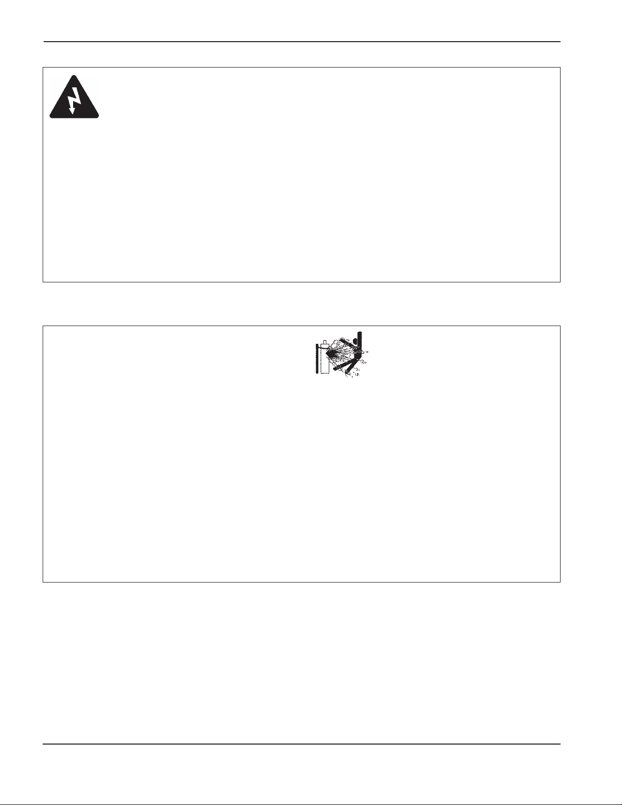
CUTTING CAN CAUSE FIRE OR EXPLOSION
WARNING
Explosion Hazard
Argon-Hydrogen and Methane
Hydrogen and methane are flammable gases that present
an explosion hazard. Keep flames away from cylinders
and hoses that contain methane or hydrogen mixtures.
Keep flames and sparks away from the torch when using
methane or argon-hydrogen plasma.
WARNING
Hydrogen Detonation
with Aluminum Cutting
• When cutting aluminum underwater, or with the water
touching the underside of the aluminum, free hydrogen
gas may collect under the workpiece and detonate
during plasma cutting operations.
• Install an aeration manifold on the floor of the water
table to eliminate the possibility of hydrogen
detonation. Refer to the Appendix section of this
manual for aeration manifold details.
Hypertherm 1-3
SAFETY
11/08
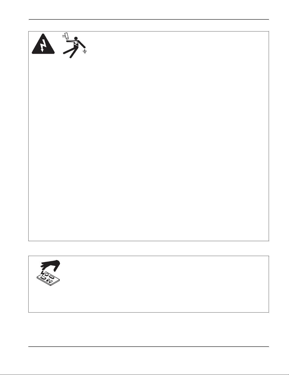
Touching live electrical parts can cause a fatal shock or
severe burn.
• Operating the plasma system completes an electrical
circuit between the torch and the workpiece. The
workpiece and anything touching the workpiece are
part of the electrical circuit.
• Never touch the torch body, workpiece or the water in
a water table when the plasma system is operating.
Electric shock prevention
All Hypertherm plasma systems use high voltage
in the cutting process (200 to 400 VDC are
common). Take the following precautions when
operating this system:
• Wear insulated gloves and boots, and keep your body
and clothing dry.
• Do not stand, sit or lie on – or touch – any wet surface
when using the plasma system.
• Insulate yourself from work and ground using dry
insulating mats or covers big enough to prevent any
physical contact with the work or ground. If you must
work in or near a damp area, use extreme caution.
• Provide a disconnect switch close to the power
supply with properly sized fuses. This switch allows
the operator to turn off the power supply quickly in
an emergency situation.
• When using a water table, be sure that it is correctly
connected to earth ground.
ELECTRIC SHOCK CAN KILL
• Install and ground this equipment according to the
instruction manual and in accordance with national
and local codes.
• Inspect the input power cord frequently for damage or
cracking of the cover. Replace a damaged power cord
immediately. Bare wiring can kill.
• Inspect and replace any worn or damaged torch leads.
• Do not pick up the workpiece, including the waste
cutoff, while you cut. Leave the workpiece in place or
on the workbench with the work cable attached during
the cutting process.
• Before checking, cleaning or changing torch parts,
disconnect the main power or unplug the power
supply.
• Never bypass or shortcut the safety interlocks.
• Before removing any power supply or system
enclosure cover, disconnect electrical input power.
Wait 5 minutes after disconnecting the main power
to allow capacitors to discharge.
• Never operate the plasma system unless the power
supply covers are in place. Exposed power supply
connections present a severe electrical hazard.
• When making input connections, attach proper
grounding conductor first.
• Each Hypertherm plasma system is designed to be
used only with specific Hypertherm torches. Do not
substitute other torches which could overheat and
present a safety hazard.
Use proper precautions when handling printed circuit
boards.
STATIC ELECTRICITY CAN DAMAGE CIRCUIT BOARDS
• Store PC boards in anti-static containers.
• Wear a grounded wrist strap when handling
PC boards.

1-4 Hypertherm
SAFETY
11/08
The plasma arc by itself is the heat source used for
cutting. Accordingly, although the plasma arc has not
been identified as a source of toxic fumes, the material
being cut can be a source of toxic fumes or gases that
deplete oxygen.
Fumes produced vary depending on the metal that is
cut. Metals that may release toxic fumes include, but
are not limited to, stainless steel, carbon steel, zinc
(galvanized), and copper.
In some cases, the metal may be coated with a substance
that could release toxic fumes. Toxic coatings include,
but are not limited to, lead (in some paints), cadmium
(in some paints and fillers), and beryllium.
Gases produced by plasma cutting vary based on the
material to be cut and the method of cutting, but may
include ozone, oxides of nitrogen, hexavalent chromium,
hydrogen, and other substances if such are contained
in or released by the material being cut.
Caution should be taken to minimize exposure to fumes
produced by any industrial process. Depending upon
the chemical composition and concentration of the
fumes (as well as other factors, such as ventilation),
there may be a risk of physical illness, such as birth
defects or cancer.
It is the responsibility of the equipment and site owner
to test the air quality in the area where the equipment is
used and to ensure that the air quality in the workplace
meets all local and national standards and regulations.
The air quality level in any relevant workplace depends
on site-specific variables such as:
• Table design (wet, dry, underwater).
• Material composition, surface finish, and composition
of coatings.
TOXIC FUMES CAN CAUSE INJURY OR DEATH
• Volume of material removed.
• Duration of cutting or gouging.
• Size, air volume, ventilation and filtration of the
work area.
• Personal protective equipment.
• Number of welding and cutting systems in operation.
• Other site processes that may produce fumes.
If the workplace must conform to national or local
regulations, only monitoring or testing done at the site
can determine whether the site is above or below
allowable levels.
To reduce the risk of exposure to fumes:
• Remove all coatings and solvents from the metal
before cutting.
• Use local exhaust ventilation to remove fumes from
the air.
• Do not inhale fumes. Wear an air-supplied respirator
when cutting any metal coated with, containing, or
suspected to contain toxic elements.
• Assure that those using welding or cutting equipment,
as well as air-supplied respiration devices, are
qualified and trained in the proper use of such
equipment.
• Never cut containers with potentially toxic materials
inside. Empty and properly clean the container first.
• Monitor or test the air quality at the site as needed.
• Consult with a local expert to implement a site plan
to ensure safe air quality.

Hypertherm 1-5
SAFETY
11/08
Instant-on torches
Plasma arc comes on immediately when the torch
switch is activated.
A PLASMA ARC CAN CAUSE INJURY AND BURNS
The plasma arc will cut quickly through gloves and skin.
• Keep away from the torch tip.
• Do not hold metal near the cutting path.
• Never point the torch toward yourself or others.
Eye protection Plasma arc rays produce intense visible and invisible (ultraviolet and infrared) rays that can
burn eyes and skin.
• Use eye protection in accordance with applicable national or local codes.
• Wear eye protection (safety glasses or goggles with side shields, and a welding helmet) with appropriate
lens shading to protect your eyes from the arc’s ultraviolet and infrared rays.
Skin protection Wear protective clothing to protect against burns caused by ultraviolet light, sparks, and
hot metal.
• Gauntlet gloves, safety shoes and hat.
• Flame-retardant clothing to cover all exposed areas.
• Cuffless trousers to prevent entry of sparks and slag.
• Remove any combustibles, such as a butane lighter or matches, from your pockets before cutting.
Cutting area Prepare the cutting area to reduce reflection and transmission of ultraviolet light:
• Paint walls and other surfaces with dark colors to reduce reflection.
• Use protective screens or barriers to protect others from flash and glare.
• Warn others not to watch the arc. Use placards or signs.
ARC RAYS CAN BURN EYES AND SKIN
Arc current
(amps)
Minimum protective
shade number
(ANSI Z49.1:2005)
Suggested shade
number for comfort
(ANSI Z49.1:2005)
OSHA 29CFR
1910.133(a)(5)
Europe
EN168:2002
Less than 40 A 5 5 8 9
41 to 60 A 6 6 8 9
61 to 80 A 8 8 8 9
81 to 125 A 8 9 8
9
126 to 150 A 8 9 8 10
151 to 175 A 8 9
8
11
176 to 250 A 8 9 8 12
251 to 300 A 8 9 8 13
301 to 400 A 9 12 9 13
401 to 800 A 10 14 10
1-6 Hypertherm
SAFETY
11/08
• Never lubricate cylinder valves or regulators with oil
or grease.
• Use only correct gas cylinders, regulators, hoses and
fittings designed for the specific application.
• Maintain all compressed gas equipment and
associated parts in good condition.
• Label and color-code all gas hoses to identify the type
of gas in each hose. Consult applicable national or
local codes.
GAS CYLINDERS CAN
EXPLODE IF DAMAGED
COMPRESSED GAS EQUIPMENT SAFETY
Gas cylinders contain gas under high pressure.
If damaged, a cylinder can explode.
• Handle and use compressed gas cylinders in
accordance with applicable national or local codes.
• Never use a cylinder that is not upright and secured
in place.
• Keep the protective cap in place over valve except
when the cylinder is in use or connected for use.
• Never allow electrical contact between the plasma arc
and a cylinder.
• Never expose cylinders to excessive heat, sparks, slag
or open flame.
• Never use a hammer, wrench or other tool to open a
stuck cylinder valve.
Work cable Attach the work cable securely to the
workpiece or the work table with good metal-to-metal
contact. Do not connect it to the piece that will fall away
when the cut is complete.
Work table Connect the work table to an earth
ground, in accordance with appropriate national or local
electrical codes.
Input power
• Be sure to connect the power cord ground wire to the
ground in the disconnect box.
• If installation of the plasma system involves
connecting the power cord to the power supply, be
sure to connect the power cord ground wire properly.
• Place the power cord's ground wire on the stud first,
then place any other ground wires on top of the power
cord ground. Fasten the retaining nut tightly.
• Tighten all electrical connections to avoid excessive
heating.
GROUNDING SAFETY
Hypertherm 1-7
SAFETY
11/08
Frozen pipes may be damaged or can burst if you
attempt to thaw them with a plasma torch.
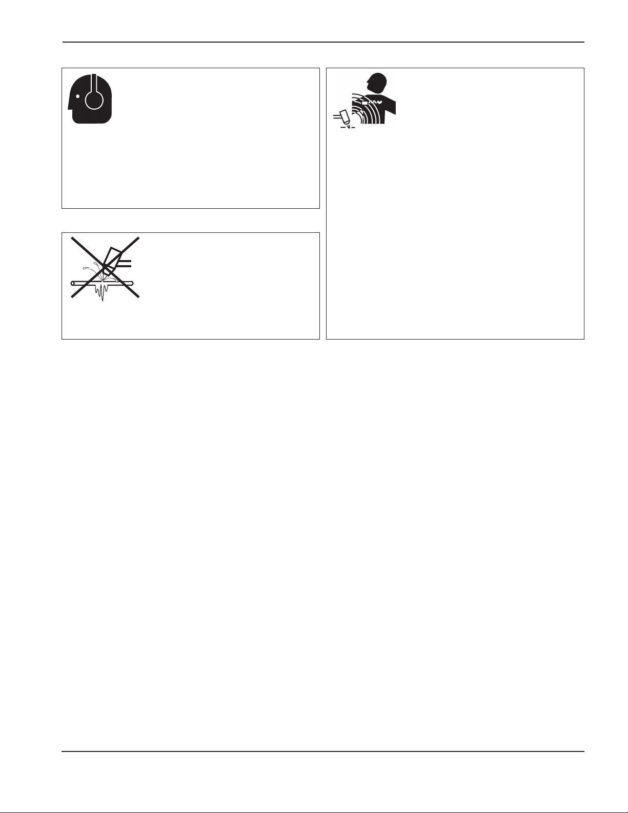
NOISE CAN DAMAGE HEARING
A PLASMA ARC CAN
DAMAGE FROZEN PIPES
Pacemaker and hearing aid operation can be affected by
magnetic fields from high currents.
Pacemaker and hearing aid wearers should consult a
doctor before going near any plasma arc cutting and
gouging operations.
To reduce magnetic field hazards:
• Keep both the work cable and the torch lead to one
side, away from your body.
• Route the torch leads as close as possible to the
work cable.
• Do not wrap or drape the torch lead or work cable
around your body.
• Keep as far away from the power supply as possible.
PACEMAKER AND
HEARING AID OPERATION
Prolonged exposure to noise from cutting or gouging
can damage hearing.
• Use approved ear protection when using plasma
system.
• Warn others nearby about the noise hazard.

1-8 Hypertherm
SAFETY
11/08
ADDITIONAL SAFETY INFORMATION
1. ANSI Standard Z49.1, Safety in Welding and Cutting, American
Welding Society, 550 LeJeune Road
P.O. Box 351020, Miami, FL 33135
2. ANSI Standard Z49.2, Fire Prevention in the Use of Cutting and
Welding Processes, American National Standards Institute
1430 Broadway, New York, NY 10018
3. ANSI Standard Z87.1, Safe Practices for Occupation and
Educational Eye and Face Protection, American National Standards
Institute, 1430 Broadway, New York, NY 10018
4. AWS F4.1, Recommended Safe Practices for the Preparation for
Welding and Cutting of Containers and Piping That Have Held
Hazardous Substances, American Welding Society
550 LeJeune Road, P.O. Box 351040, Miami, FL 33135
5. AWS F5.2, Recommended Safe Practices for Plasma Arc
Cutting, American Welding Society
550 LeJeune Road, P.O. Box 351040, Miami, FL 33135
6. CGA Pamphlet P-1, Safe Handling of Compressed Gases in
Cylinders, Compressed Gas Association
1235 Jefferson Davis Highway, Arlington, VA 22202
7. CSA Standard W117.2, Code for Safety in Welding and Cutting,
Canadian Standards Association Standard Sales
178 Rexdale Boulevard, Rexdale, Ontario M9W 1R3, Canada
8. NFPA Standard 51B, Cutting and Welding Processes, National Fire
Protection Association
470 Atlantic Avenue, Boston, MA 02210
9. NFPA Standard 70–1978, National Electrical Code, National Fire
Protection Association, 470 Atlantic Avenue, Boston, MA 02210
10. OSHA, Safety and Health Standards, 29FR 1910
U.S. Government Printing Office, Washington, D.C. 20402
11. AWS Safety and Health Fact Sheets, American Welding Society
550 LeJeune Road, P.O. Box 351040, Miami, FL 33135
www.aws.org/technical/facts/
SYMBOLS AND MARKS
Your Hypertherm product may have one or more of the following markings on or near the data plate. Due to differences
and conflicts in national regulations, not all marks are applied to every version of a product.
S mark symbol
The S mark symbol indicates that the power supply and torch are suit able for operations carried out in
en vi ron ments with in creased hazard of elec tri cal shock per IEC 60974-1.
CSA mark
Hypertherm products with a CSA mark meet the United States and Canadian regulations for product safety.
The products were evaluated, tested, and certified by CSA-International. Alternatively the product may have
a mark by one of the other Nationally Recognized Testing Laboratories (NRTL) accredited in both the United
States and Canada, such as Underwriters Laboratories, Incorporated (UL) or TÜV.
CE marking
The CE marking signifies the manufacturer’s declaration of conformity to applicable European directives
and standards. Only those versions of Hypertherm products with a CE marking located on or near the
data plate have been tested for compliance with the European Low Voltage Directive and the European
Electromagnetic Compatibility (EMC) Directive. EMC filters needed to comply with the European EMC
Directive are incorporated within versions of the product with a CE marking.
GOST-R mark
CE versions of Hypertherm products that include a GOST-R mark of conformity meet the product safety
and EMC requirements for export to the Russian Federation.
c-Tick mark
CE versions of Hypertherm products with a c-Tick mark comply with the EMC regulations required for sale
in Australia and New Zealand.
CCC mark
The China Compulsory Certification (CCC) mark indicates that the product has been tested and found
compliant with product safety regulations required for sale in China.
Hypertherm 1-9
SAFETY
11/08
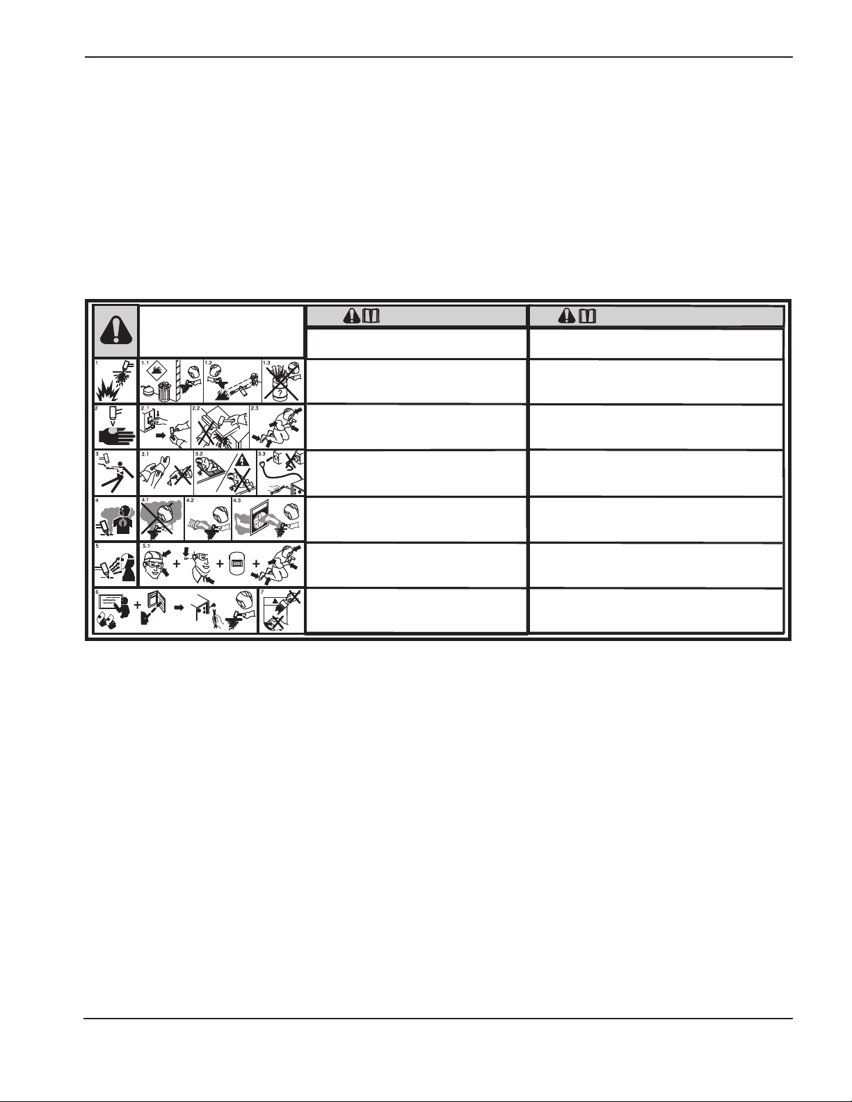
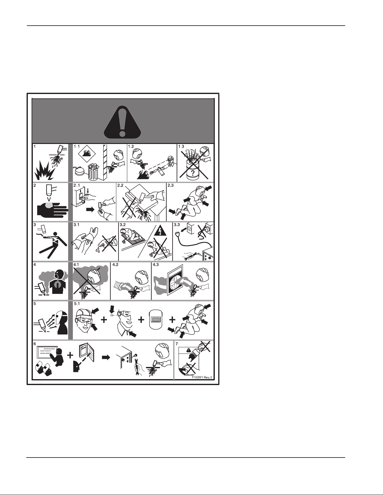
WARNING LABEL
This warning label is affixed to some power supplies. It is important
that the operator and maintenance technician understand the intent
of these warning symbols as described.
Read and follow these instructions, employer safety
practices, and material safety data sheets. Refer to
ANS Z49.1, “Safety in Welding, Cutting and Allied
Processes” from American Welding Society
(http://www.aws.org) and OSHA Safety and Health
Standards, 29 CFR 1910 (http://www.osha.gov).
WARNING
Plasma cutting can be injurious to operator and persons
in the work area. Consult manual before operating. Failure
to follow all these safety instructions can result in death.
1. Cutting sparks can cause explosion or fire.
1.1 Do not cut near flammables.
1.2 Have a fire extinguisher nearby and ready to use.
1.3 Do not use a drum or other closed container as a cutting table.
2. Plasma arc can injure and burn; point the nozzle away
from yourself. Arc starts instantly when triggered.
2.1 Turn off power before disassembling torch.
2.2 Do not grip the workpiece near the cutting path.
2.3 Wear complete body protection.
3. Hazardous voltage. Risk of electric shock or burn.
3.1 Wear insulating gloves. Replace gloves when wet or damaged.
3.2 Protect from shock by insulating yourself from work and ground.
3.3 Disconnect power before servicing. Do not touch live parts.
4. Plasma fumes can be hazardous.
4.1 Do not inhale fumes.
4.2 Use forced ventilation or local exhaust to remove the fumes.
4.3 Do not operate in closed spaces. Remove fumes with ventilation.
5. Arc rays can burn eyes and injure skin.
5.1 Wear correct and appropriate protective equipment to protect
head, eyes, ears, hands, and body. Button shirt collar. Protect ears
from noise. Use welding helmet with the correct shade of filter.
6. Become trained.
equipment. Use torches specified in the manual. Keep non-qualified
personnel and children away.
7. Do not remove, destroy, or cover this label.
Replace if it is missing, damaged, or worn (PN 110584 Rev C).
Only qualified personnel should operate this
AVERTISSEMENT
Le coupage plasma peut être préjudiciable pour l’opérateur et les personnes qui se
trouvent sur les lieux de travail. Consulter le manuel avant de faire fonctionner. Le
non respect des ces instructions de sécurité peut entraîner la mort.
1. Les étincelles de coupage peuvent provoquer une explosion
ou un incendie.
1.1 Ne pas couper près des matières inflammables.
1.2 Un extincteur doit être à proximité et prêt à être utilisé.
1.3 Ne pas utiliser un fût ou un autre contenant fermé comme table de coupage.
2. L’arc plasma peut blesser et brûler; éloigner la buse de soi.
Il s’allume instantanément quand on l’amorce;
2.1 Couper l’alimentation avant de démonter la torche.
2.2 Ne pas saisir la pièce à couper de la trajectoire de coupage.
2.3 Se protéger entièrement le corps.
3. Tension dangereuse. Risque de choc électrique ou de brûlure.
3.1 Porter des gants isolants. Remplacer les gants quand ils sont humides ou
endommagés.
3.2 Se protéger contre les chocs en s’isolant de la pièce et de la terre.
3.3 Couper l’alimentation avant l’entretien. Ne pas toucher les pièces sous tension.
4. Les fumées plasma peuvent être dangereuses.
4.1 Ne pas inhaler les fumées
4.2 Utiliser une ventilation forcée ou un extracteur local pour dissiper les fumées.
4.3 Ne pas couper dans des espaces clos. Chasser les fumées par ventilation.
5. Les rayons d’arc peuvent brûler les yeux et blesser la peau.
5.1 Porter un bon équipement de protection pour se protéger la tête, les yeux, les
oreilles, les mains et le corps. Boutonner le col de la chemise. Protéger les oreilles
contre le bruit. Utiliser un masque de soudeur avec un filtre de nuance appropriée.
6. Suivre une formation. Seul le personnel qualifié a le droit de faire
fonctionner cet équipement. Utiliser exclusivement les torches indiquées dans le
manual. Le personnel non qualifié et les enfants doivent se tenir à l’écart.
7. Ne pas enlever, détruire ni couvrir cette étiquette.
La remplacer si elle est absente, endommagée ou usée (PN 110584 Rev C).
1-10 Hypertherm
SAFETY
11/08
WARNING LABEL
This warning label is affixed to some power supplies. It is important
that the operator and maintenance technician understand the intent of
these warning symbols as described. The numbered text corresponds
to the numbered boxes on the label.
1. Cutting sparks can cause explosion
or fire.
1.1 Do not cut near flammables.
1.2 Have a fire extinguisher nearby and
ready to use.
1.3 Do not use a drum or other closed
container as a cutting table.
2. Plasma arc can injure and burn; point
the nozzle away from yourself. Arc starts
instantly when triggered.
2.1 Turn off power before disassembling
torch.
2.2 Do not grip the workpiece near the
cutting path.
2.3 Wear complete body protection.
3. Hazardous voltage. Risk of electric
shock or burn.
3.1 Wear insulating gloves. Replace gloves
when wet or damaged.
3.2 Protect from shock by insulating yourself
from work and ground.
3.3 Disconnect power before servicing. Do
not touch live parts.
4. Plasma fumes can be hazardous.
4.1 Do not inhale fumes.
4.2 Use forced ventilation or local exhaust to
remove the fumes.
4.3 Do not operate in closed spaces.
Remove fumes with ventilation.
5. Arc rays can burn eyes and injure skin.
5.1 Wear correct and appropriate protective
equipment to protect head, eyes, ears,
hands, and body. Button shirt collar.
Protect ears from noise. Use welding
helmet with the correct shade of filter.
6. Become trained. Only qualified
personnel should operate this
equipment. Use torches specified in the
manual. Keep non-qualified personnel
and children away.
7. Do not remove, destroy, or cover this
label. Replace if it is missing, damaged,
or worn.

Hypertherm 1-11
SAFETY
11/08
Dry dust collection information
At some sites, dry dust can represent a potential explosion hazard.
The U.S. National Fire Protection Association’s 2007 edition of NFPA standard 68, “Explosion Protection by
Deflagration Venting,” provides requirements for the design, location, installation, maintenance, and use of devices and
systems to vent combustion gases and pressures after any deflagration event. Consult with the manufacturer or installer
of any dry dust collection system for applicable requirements before you install a new dry dust collection system or make
significant changes in the process or materials used with an existing dry dust collection system.
Consult your local “Authority Having Jurisdiction” (AHJ) to determine whether any edition of NFPA 68 has been
“adopted by reference” in your local building codes.
Refer to NFPA68 for definitions and explanations of regulatory terms such as deflagration, AHJ, adopted by reference,
the Kst value, deflagration index, and other terms.
Note 1 – Hypertherm’s interpretation of these new requirements is that unless a site-specific evaluation has been
completed to determine that all dust generated is not combustible, the 2007 edition of NFPA 68 requires the use of
explosion vents designed to the worst-case Kst value (see annex F) that could be generated from dust so that the
explosion vent size and type can be designed. NFPA 68 does not specifically identify plasma cutting or other thermal
cutting processes as requiring deflagration venting systems, but it does apply these new requirements to all dry dust
collection systems.
Note 2 – Users of Hypertherm manuals should consult and comply with all applicable federal, state, and local laws and
regulations. Hypertherm does not, by the publication of any Hypertherm manual, intend to urge action that is not in
compliance with all applicable regulations and standards, and this manual may never be construed as doing so.

Hypertherm 1a-1
11/08
Section 1a
SÉCURITÉ
Dans cette section :
Identifier les consignes de sécurité .....................................................................................................................................................1a-2
Suivre les instructions de sécurité .......................................................................................................................................................1a-2
Le coupage peut provoquer un incendie ou une explosion ...........................................................................................................1a-2
Les chocs électriques peuvent être fatals..........................................................................................................................................1a-3
L’électricité statique peut endommager les cartes de circuits imprimés ....................................................................................1a-3
Les vapeurs toxiques peuvent provoquer des blessures ou la mort ............................................................................................1a-4
L’arc plasma peut provoquer des blessures ou des brûlures ........................................................................................................1a-5
Les rayons de l’arc peuvent brûler les yeux et la peau....................................................................................................................1a-5
Mise à la masse et à la terre..................................................................................................................................................................1a-6
Sécurité des bouteilles de gaz comprimé ..........................................................................................................................................1a-6
Les bouteilles de gaz comprimé peuvent exploser en cas de dommages .................................................................................1a-6
Le bruit peut provoquer des problèmes auditifs ...............................................................................................................................1a-7
Pacemakers et prothèses auditives .....................................................................................................................................................1a-7
Un arc plasma peut endommager les tuyaux gelés..........................................................................................................................1a-7
Symboles et marquage...........................................................................................................................................................................1a-8
Étiquettes de sécurité .............................................................................................................................................................................1a-9
Information sur le dépoussiérage.......................................................................................................................................................1a-11
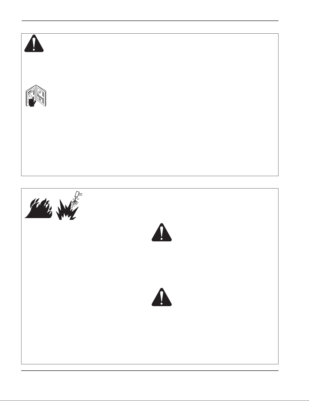
1a-2 Hypertherm
SÉCURITÉ
11/08
IDENTIFIER LES CONSIGNES
DE SÉCURITÉ
Les symboles indiqués dans cette section sont utilisés pour
identifier les risques éventuels. Si vous trouvez un symbole de
sécurité, que ce soit dans ce manuel ou sur l’équipement, soyez
conscient des risques de blessures et suivez les instructions
correspondantes afin d’éviter ces risques.
SUIVRE LES INSTRUCTIONS
DE SÉCURITÉ
Lire attentivement toutes les consignes de sécurité dans
le présent manuel et sur les étiquettes de sécurité se trouvant
sur la machine.
• Les étiquettes de sécurité doivent rester lisibles. Remplacer
immédiatement les étiquettes manquantes ou abîmées.
• Apprendre à faire fonctionner la machine et à utiliser
correctement les commandes. Ne laisser personne utiliser
la machine sans connaître son fonctionnement.
• Garder la machine en bon état. Des modifications non
autorisées sur la machine peuvent engendrer des problèmes
de sécurité et raccourcir la durée d’utilisation de l’équipement.
DANGER AVERTISSEMENT ATTENTION
Hypertherm adopte les lignes directrices de l’American
National Standards Institute relativement aux termes, aux
symboles et à la signalisation de sécurité. Les signaux
DANGER ou AVERTISSEMENT sont utilisés avec un
symbole de sécurité, DANGER correspondant aux risques
les plus sérieux.
• Les étiquettes de sécurité DANGER et AVERTISSE MENT
sont situées sur la machine pour signaler certains dangers
spécifiques.
• Les messages de sécurité DANGER précèdent les
directives associées dans le manuel qui, si elles ne sont pas
suivies scrupuleusement, entraînent des blessures graves
voire mortelles.
• Les messages d’AVERTISSEMENT précèdent les
instructions d’utilisation expliquées dans ce manuel
et signalent les risques de blessures ou de mort au cas
où ces instructions ne seraient pas suivies correctement.
• Les messages de sécurité ATTENTION précèdent les
directives associées dans le manuel qui, si elles ne sont pas
suivies scrupuleusement, peuvent entraîner des blessures
secondaires ou endommager l’équipement.
Prévention des incendies
• Avant de commencer, s’assurer que la zone de coupage ne
présente aucun danger. Conserver un extincteur à proximité.
• Éloigner toute matière inflammable à une distance d’au
moins 10 m du poste de coupage.
• Tremper le métal chaud ou le laisser refroidir avant
de le manipuler ou avant de le mettre en contact avec
des matériaux combustibles.
• Ne jamais couper des récipients pouvant contenir des
matières inflammables avant de les avoir vidés et nettoyés
correctement.
• Aérer toute atmosphère potentiellement inflammable avant
d’utiliser un système plasma.
• Lors de l’utilisation d’oxygène comme gaz plasma, un
système de ventilation par aspiration est nécessaire.
Prévention des explosions
• Ne pas couper en présence de poussière ou de vapeurs.
• Ne pas couper de bouteilles, de tuyaux ou autres récipients
fermés et pressurisés.
• Ne pas couper de récipients contenant des matières
combustibles.
LE COUPAGE PEUT PROVOQUER UN INCENDIE
OU UNE EXPLOSION
AVERTISSEMENT
Risque d’explosion
argon-hydrogène et méthane
L’hydrogène et le méthane sont des gaz inflammables et
potentiellement explosifs. Conserver à l’écart de toute flamme
les bouteilles et tuyaux contenant des mélanges à base
d’hydrogène ou de méthane. Maintenir toute flamme et étincelle
à l’écart de la torche lors de l’utilisation d’un plasma
d’argon-hydrogène ou de méthane.
AVERTISSEMENT
Détonation de l’hydrogène lors du
coupage de l’aluminium
• Lors du coupage de l’aluminium sous l’eau, ou si l’eau touche
la partie inférieure de la pièce d’aluminium, de l’hydrogène
libre peut s’accumuler sous la pièce à couper et détonner
lors du coupage plasma.
• Installer un collecteur d’aération au fond de la table à eau afin
d’éliminer les risques de détonation de l’hydrogène.
Se référer à l’annexe du manuel pour plus de renseignements
sur les collecteurs d’aération.
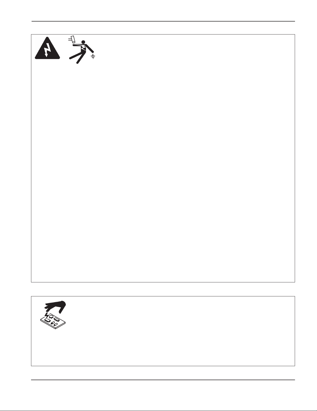
Toucher une pièce électrique sous tension peut provoquer
un choc électrique fatal ou des brûlures graves.
• La mise en fonctionnement du système plasma ferme
un circuit électrique entre la torche et la pièce à couper.
La pièce à couper et tout autre élément en contact avec
cette pièce font partie du circuit électrique.
• Ne jamais toucher le corps de la torche, la pièce à couper
ou l’eau de la table à eau pendant le fonctionnement
du système plasma.
Prévention des chocs électriques
Tous les systèmes plasma Hypertherm utilisent des hautes
tensions pour le coupage (souvent de 200 à 400 V).
On doit prendre les précautions suivantes quand on utilise
le système plasma :
• Porter des bottes et des gants isolants et garder le corps
et les vêtements au sec.
• Ne pas se tenir, s’asseoir ou se coucher sur une surface
mouillée, ni la toucher quand on utilise le système plasma.
• S’isoler de la surface de travail et du sol en utilisant des
tapis isolants secs ou des couvertures assez grandes pour
éviter tout contact physique avec le travail ou le sol. S’il
s’avère nécessaire de travailler dans ou près d’un endroit
humide, procéder avec une extrême prudence.
• Installer un sectionneur avec fusibles appropriés, à proximité
de la source de courant. Ce dispositif permet à l’opérateur
d’arrêter rapidement la source de courant en cas d’urgence.
• En cas d’utilisation d’une table à eau, s’assurer que cette
dernière est correctement mise à la terre.
• Installer et mettre à la terre l’équipement selon les
instructions du présent manuel et conformément aux codes
électriques locaux et nationaux.
LES CHOCS ÉLECTRIQUES PEUVENT ÊTRE FATALS
• Inspecter fréquemment le cordon d’alimentation primaire
pour s’assurer qu’il n’est ni endommagé, ni fendu. Remplacer
immédiatement un cordon endommagé. Un câble dénudé
peut tuer.
• Inspecter et remplacer les câbles de la torche qui sont usés
ou endommagés.
• Ne pas saisir la pièce à couper ni les chutes lors du
coupage. Laisser la pièce à couper en place ou sur la table
de travail, le câble de retour connecté lors du coupage.
• Avant de vérifier, de nettoyer ou de remplacer les pièces
de la torche, couper l’alimentation ou débrancher la prise
de courant.
• Ne jamais contourner ou court-circuiter les verrouillages
de sécurité.
• Avant d’enlever le capot du système ou de la source de
courant, couper l’alimentation électrique. Attendre en
suite
5 minutes pour que les condensateurs se déchargent.
• Ne jamais faire fonctionner le système plasma sans que
les capots de la source de courant ne soient en place.
Les raccords exposés de la source de courant sont
extrêmement dangereux.
• Lors de l’installation des connexions, attacher tout d’abord
la prise de terre appropriée.
• Chaque système plasma Hypertherm est conçu pour
être utilisé uniquement avec des torches Hypertherm
spécifiques. Ne pas utiliser des torches inappropriées
qui pourraient surchauffer et présenter des risques pour
la sécurité.
On doit prendre les précautions qui s’imposent quand on
manipule les circuits imprimés.
L’ÉLECTRICITÉ STATIQUE PEUT ENDOMMAGER
LES CARTES DE CIRCUITS IMPRIMÉS
• On doit ranger les cartes de circuits imprimés dans des
contenants antistatiques.
• On doit porter un bracelet antistatique quand on manipule
les cartes de circuits imprimés.
Hypertherm 1a-3
SÉCURITÉ
11/08

1a-4 Hypertherm
SÉCURITÉ
11/08
L’arc plasma est lui-même la source de chaleur utilisée pour le
coupage. Par conséquent, bien que l’arc plasma n’ait pas été
reconnu comme une source de vapeurs toxiques, le matériau
coupé peut être une source de vapeurs ou de gaz toxiques
qui épuisent l’oxygène.
Les vapeurs produites varient selon le métal coupé.
Les métaux qui peuvent dégager des vapeurs toxiques
comprennent, entre autres, l’acier inoxydable, l’acier au
carbone, le zinc (galvanisé) et le cuivre.
Dans certains cas, le métal peut être revêtu d’une substance
susceptible de dégager des vapeurs toxiques. Les
revêtements toxiques comprennent entre autres, le plomb
(dans certaines peintures), le cadmium (dans certaines
peintures et enduits) et le béryllium.
Les gaz produits par le coupage plasma varient selon
le matériau à couper et la méthode de coupage, mais
ils peuvent comprendre l’ozone, les oxydes d’azote, le chrome
hexavalent, l’hydrogène et autres substances présentes dans
le matériau coupé ou en émanent.
On doit prendre les précautions qui s’imposent pour réduire
au minimum l’exposition aux vapeurs produites par tout
processus industriel. Selon la composition chimique et la
concentration des vapeurs (ainsi que d’autres facteurs comme
la ventilation), il peut y avoir un risque de maladie physique,
comme des malformations ou le cancer.
Il incombe au propriétaire du matériel et du site de vérifier la
qualité de l’air dans le secteur où l’on utilise le matériel et de
s’assurer que la qualité de l’air sur les lieux de travail répond
aux normes et réglementation locales et nationales.
Le niveau de qualité de l’air dans tout lieu de travail dépend
des variables propres au site comme :
• Type de table (humide, sèche, sous l’eau).
• Composition du matériau, fini de la surface et composition
des revêtements.
LES VAPEURS TOXIQUES PEUVENT PROVOQUER
DES BLESSURES OU LA MORT
• Volume de matériau enlevé.
• Durée du coupage ou du gougeage.
• Dimensions, volume d’air, ventilation et filtration de la zone
de travail.
• Équipement de protection individuelle.
• Nombre de systèmes de soudage et de coupage
en fonctionnement.
• Autres procédés du site qui peuvent produire des vapeurs.
Si les lieux de travail doivent être conformes aux règlements
nationaux ou locaux, seuls les contrôles ou les essais effectués
au site peuvent déterminer si celui-ci se situe au-dessus ou
au-dessous des niveaux admissibles.
Pour réduire le risque d’exposition aux vapeurs :
• Éliminer tout revêtement et solvant du métal avant
le coupage.
• Utiliser la ventilation d’extraction locale pour éliminer les
vapeurs de l’air.
• Ne pas inhaler les vapeurs. Porter un respirateur à adduction
d’air quand on coupe des métaux revêtus d’éléments
toxiques ou qui en contiennent ou sont susceptibles d’en
contenir.
• S’assurer que les personnes qui utilisent un matériel de
soudage ou de coupage ainsi que les dispositifs de
respiration par adduction d’air sont qualifiés et ont reçu
la formation sur la bonne utilisation d’un tel matériel.
• Ne jamais couper les contenants dans lesquels il peut
y avoir des matériaux toxiques. En premier lieu, vider
et nettoyer correctement le contenant.
• Contrôler ou éprouver la qualité de l’air au site selon les
besoins.
• Consulter un expert local pour mettre en œuvre un plan
du site afin d’assurer une qualité de l’air sûre.
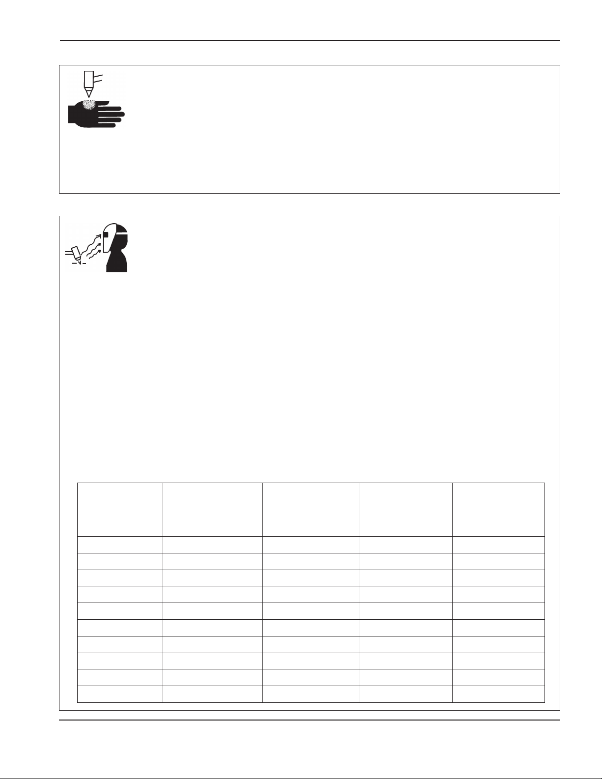
Torches à allumage instantané
L’arc plasma s’allume immédiatement après que la torche soit
mise en marche.
L’ARC PLASMA PEUT PROVOQUER DES BLESSURES OU DES BRÛLURES
L’arc plasma coupe facilement les gants et la peau.
• Rester éloigné de l’extrémité de la torche.
• Ne pas tenir de métal près de la trajectoire de coupe.
• Ne jamais pointer la torche vers soi ou d’autres personnes.
Hypertherm 1a-5
SÉCURITÉ
11/08
Protection des yeux Les rayons de l’arc plasma produisent de puissants rayons visibles ou invisibles (ultraviolets et infrarouges)
qui peuvent brûler les yeux et la peau.
• Utiliser des lunettes de sécurité conformément aux codes locaux ou nationaux en vigueur.
• Porter des lunettes de protection (lunettes ou masque muni d’écrans latéraux et encore masque de soudure) avec des verres
teintés appropriés pour protéger les yeux des rayons ultraviolets et infrarouges de l’arc.
Protection de la peau Porter des vêtements de sécurité pour se protéger contre les brûlures que peuvent causer les rayons
ultraviolets, les étincelles et le métal brûlant :
• Gants à crispin, chaussures et casque de sécurité.
• Vêtements ignifuges couvrant toutes les parties exposées du corps.
• Pantalon sans revers pour éviter que des étincelles ou des scories puissent s’y loger.
• Avant le coupage, retirer de ses poches tout objet combustible comme les briquets au butane ou les allumettes.
Zone de coupage Préparer la zone de coupage afin de réduire la réverbération et la transmission de la lumière ultraviolette :
• Peindre les murs et autres surfaces de couleur sombre pour réduire la réflexion de la lumière.
• Utiliser des écrans et autres dispositifs de protection afin de protéger les autres personnes de la lumière et de la réverbération.
• Prévenir les autres personnes de ne pas regarder l’arc. Utiliser des affiches ou des panneaux.
LES RAYONS DE L’ARC PEUVENT BRÛLER LES YEUX ET LA PEAU
Courant de l’arc
(A)
Indice de protection
minimum (ANSI
Z49.1:2005)
Indice de protection
suggéré pour
assurer le confort
(ANSI Z49.1:2005)
OSHA 29CFR
1910.133(a)(5)
Europe
EN168:2002
Moins de 40 A 5 5 8 9
41 à 60 A 6 6 8 9
61 à 80 A 8 8 8 9
81 à 125 A 8 9 8
9
126 à 150 A 8 9 8 10
151 à 175 A 8 9
8
11
176 à 250 A 8 9 8 12
251 à 300 A 8 9 8 13
301 à 400 A 9 12 9 13
401 à 800 A 10 14 10

1a-6 Hypertherm
SÉCURITÉ
11/08
• Ne jamais lubrifier les robinets des bouteilles ou les
régulateurs avec de l’huile ou de la graisse.
• Utiliser uniquement les bouteilles, régulateurs, tuyaux et
accessoires appropriés et conçus pour chaque application
spécifique.
• Entretenir l’équipement et les pièces d’équipement à gaz
comprimé afin de les garder en bon état.
• Étiqueter et coder avec des couleurs tous les tuyaux de gaz
afin d’identifier le type de gaz contenu dans chaque tuyau.
Se référer aux codes locaux ou nationaux en vigueur.
LES BOUTEILLES DE GAZ
COMPRIMÉ PEUVENT
EXPLOSER EN CAS DE
DOMMAGES
SÉCURITÉ DES BOUTEILLES
DE GAZ COMPRIMÉ
Les bouteilles de gaz contiennent du gaz à haute pression.
Si une bouteille est endommagée, elle peut exploser.
• Manipuler et utiliser les bouteilles de gaz comprimé
conformément aux codes locaux ou nationaux.
• Ne jamais utiliser une bouteille qui n’est pas placée
à la verticale et bien assujettie.
• Le capuchon de protection doit être placé sur le robinet
sauf si la bouteille est en cours d’utilisation ou connectée
pour utilisation.
• Éviter à tout prix le contact électrique entre l’arc plasma
et une bouteille.
• Ne jamais exposer des bouteilles à une chaleur excessive,
aux étincelles, aux scories ou aux flammes nues.
• Ne jamais utiliser des marteaux, des clés ou d’autres outils
pour débloquer le robinet des bouteilles.
Câble de retour Bien fixer le câble de retour (ou de masse)
à la pièce à couper ou à la table de travail de façon à assurer
un bon contact métal-métal. Ne pas fixer le câble de retour
à la partie de la pièce qui doit se détacher.
Table de travail Raccorder la table de travail à la terre,
conformément aux codes de sécurité locaux ou nationaux
appropriés.
Alimentation
• S’assurer que le fil de terre du cordon d’alimentation est
connecté à la terre dans le coffret du sectionneur.
• S’il est nécessaire de brancher le cordon d’alimentation à la
source de courant lors de l’installation du système, s’assurer
que le fil de terre est correctement branché.
• Placer tout d’abord le fil de terre du cordon d’alimentation
sur le plot de mise à la terre puis placer les autres fils de
terre par-dessus. Bien serrer l’écrou de retenue.
• S’assurer que toutes les connexions sont bien serrées pour
éviter la surchauffe.
MISE À LA MASSE ET À LA TERRE
 Loading...