

Page 1

EDGE® Connect
Shape Cutting Control
Installation and Setup Manual
809340 | Revision 4 | English
Page 2

Register your new Hypertherm system
Benefits of registration
5 Safety: Registration allows us to contact you in the unlikely event a safety or quality notification
is required.
5 Education: Registration gives you free access to online product training content via the
Hypertherm Cutting Institute.
5 Confirmation of ownership: Registration can serve as proof of purchase in case of an
insurance loss.
Go to www.hypertherm.com/registration for easy and fast registration.
If you experience any problems with the product registration process, please contact
registration@hypertherm.com.
For your records
Serial number: __________________________________________________________________________
Purchase date: __________________________________________________________________________
Distributor: _____________________________________________________________________________
_______________________________________________________________________________________
_______________________________________________________________________________________
Maintenance notes: ______________________________________________________________________
_______________________________________________________________________________________
_______________________________________________________________________________________
_______________________________________________________________________________________
_______________________________________________________________________________________
EDGE, Phoenix, HPR, HPRXD, HPR130XD, HPR260XD, HPR400XD, CutPro, Remote Help, XPR, Powermax, and Hypertherm
are trademarks of Hypertherm Inc. and may be registered in the United States and other countries. EtherCAT is a trademark of
Beckhoff Automation. All other trademarks are the property of their respective holders.
Environmental stewardship is one of Hypertherm’s core values, and it is critical to our success and our customers’ success. We
are striving to reduce the environmental impact of everything we do. For more information:www.hypertherm.com/environment
© 2020 Hypertherm, Inc.
.
Page 3

EDGE Connect
Installation and Setup Manual
809340
Revision 4
English
Original Instructions
October 2020
Hypertherm, Inc.
Hanover, NH 03755 USA
www.hypertherm.com
Page 4

Hypertherm Europe B.V.
Vaartveld 9, 4704 SE
Roosendaal, Nederland
31 165 596907 Tel
31 165 596901 Fax
31 165 596908 Tel (Marketing)
31 (0) 165 596900 Tel (Technical Service)
00 800 4973 7843 Tel (Technical Service)
technicalservice.emea@hypertherm.com
(Technical Service Email)
Hypertherm (Shanghai) Trading Co., Ltd.
B301, 495 ShangZhong Road
Shanghai, 200231
PR China
86-21-80231122 Tel
86-21-80231120 Fax
86-21-80231128 Tel (Technical Service)
techsupport.china@hypertherm.com
(Technical Service Email)
South America & Central America: Hypertherm Brasil Ltda.
Rua Bras Cubas, 231 – Jardim Maia
Guarulhos, SP – Brasil
CEP 07115-030
55 11 2409 2636 Tel
tecnico.sa@hypertherm.com (Technical Service Email)
Hypertherm Korea Branch
#3904. APEC-ro 17. Heaundae-gu. Busan.
Korea 48060
82 (0)51 747 0358 Tel
82 (0)51 701 0358 Fax
Marketing.korea@hypertherm.com (Marketing Email)
TechSupportAPAC@hypertherm.com
(Technical Service Email)
Hypertherm Pty Limited
GPO Box 4836
Sydney NSW 2001, Australia
61 (0) 437 606 995 Tel
61 7 3219 9010 Fax
au.sales@Hypertherm.com (Main Office Email)
TechSupportAPAC@hypertherm.com
(Technical Service Email)
Hypertherm (India) Thermal Cutting Pvt. Ltd
A-18 / B-1 Extension,
Mohan Co-Operative Industrial Estate,
Mathura Road, New Delhi 110044, India
91-11-40521201/ 2/ 3 Tel
91-11 40521204 Fax
HTIndia.info@hypertherm.com (Main Office Email)
TechSupportAPAC@hypertherm.com
(Technical Service Email)
Hypertherm, Inc.
Etna Road, P.O. Box 5010
Hanover, NH 03755 USA
603-643-3441 Tel (Main Office)
603-643-5352 Fax (All Departments)
info@hypertherm.com (Main Office Email)
800-643-9878 Tel (Technical Service)
technical.service@hypertherm.com (Technical Service Email)
800-737-2978 Tel (Customer Service)
customer.service@hypertherm.com (Customer Service Email)
866-643-7711 Tel (Return Materials Authorization)
877-371-2876 Fax (Return Materials Authorization)
return.materials@hypertherm.com (RMA email)
Hypertherm México, S.A. de C.V.
Avenida Toluca No. 444, Anexo 1,
Colonia Olivar de los Padres
Delegación Álvaro Obregón
México, D.F. C.P. 01780
52 55 5681 8109 Tel
52 55 5683 2127 Fax
Soporte.Tecnico@hypertherm.com (Technical Service Email)
Hypertherm Plasmatechnik GmbH
Sophie-Scholl-Platz 5
63452 Hanau
Germany
00 800 33 24 97 37 Tel
00 800 49 73 73 29 Fax
31 (0) 165 596900 Tel (Technical Service)
00 800 4973 7843 Tel (Technical Service)
technicalservice.emea@hypertherm.com (Technical Service Email)
Hypertherm (Singapore) Pte Ltd.
82 Genting Lane
Media Centre
Annexe Block #A01-01
Singapore 349567, Republic of Singapore
65 6841 2489 Tel
65 6841 2490 Fax
Marketing.asia@hypertherm.com (Marketing Email)
TechSupportAPAC@hypertherm.com (Technical Service Email)
Hypertherm Japan Ltd.
Level 9, Edobori Center Building
2-1-1 Edobori, Nishi-ku
Osaka 550-0002 Japan
81 6 6225 1183 Tel
81 6 6225 1184 Fax
HTJapan.info@hypertherm.com (Main Office Email)
TechSupportAPAC@hypertherm.com (Technical Service Email)
For training and education resources, go to the Hypertherm Cutting Institute (HCI) online at
www.hypertherm.com/hci.
Page 5

ENGLISH
WARNING! Before operating any Hypertherm equipment, read the safety
instructions in your product’s manual, the Safety and Compliance Manual
(80669C), Waterjet Safety and Compliance Manual (80943C), and
Radio Frequency Warning Manual (80945C). Failure to follow safety
instructions can result in personal injury or in damage to equipment.
Copies of the manuals may accompany the product in electronic and printed
formats. You can also obtain copies of the manuals, in all languages available
for each manual, from the “Documents library” at www.hypertherm.com.
BG (БЪЛГAPCКИ/BULGARIAN)
ПРЕДУПРЕЖДЕНИЕ! Преди да работите с което и да е оборудване
Hypertherm, прочетете инструкциите за безопасност в ръководството
на вашия продукт, „Инструкция за безопасност и съответствие“ (80669C),
„Инструкция за безопасност и съответствие на Waterjet“ (80943С)
и „Инструкция за предупреждение за радиочестота“ (80945С).
Копия на ръководствата може да придружават продукта в електронен
и в печатен формат. Можете да получите копия на ръководствата,
предлагани на всички езици, от „Documents library“ (Библиотека
за документи) на адрес www.hypertherm.com.
ET (EESTI/ESTONIAN)
HOIATUS! Enne Hyperthermi mis tahes seadme kasutamist lugege läbi toote
kasutusjuhendis olevad ohutusjuhised ning Ohutus- ja vastavusjuhend
(80669C), Veejoa ohutuse ja vastavuse juhend (80943C) ja Raadiosageduse
hoiatusjuhend (80945C). Ohutusjuhiste eiramine võib põhjustada vigastusi
ja kahjustada seadmeid.
Juhiste koopiad võivad olla tootega kaasas elektroonilises ja trükivormingus.
Juhiste koopiaid kõigis iga käsiraamatu jaoks saadaolevas keeles saate
hankida ka „Documents library (dokumentide raamatukogust)” lehel
www.hypertherm.com.
FI (SUOMI/FINNISH)
VAROITUS! Ennen minkään Hypertherm-laitteen käyttöä lue
tuotteen käyttöoppaassa olevat turvallisuusohjeet, turvallisuuden
ja vaatimustenmukaisuuden käsikirja (80669C), vesileikkauksen
turvallisuuden ja vaatimustenmukaisuuden käsikirja (80943C)
ja radiotaajuusvaroitusten käsikirja (80945C).
Käyttöoppaiden kopiot voivat olla tuotteen mukana elektronisessa
ja tulostetussa muodossa. Voit saada käyttöoppaiden kopiot kaikilla
kielillä ”latauskirjastosta”, joka on osoitteessa www.hypertherm.com.
CS (ČESKY/CZECH)
VAROVÁNÍ! Před uvedením jakéhokoli zařízení Hypertherm do provozu
si přečtěte bezpečnostní pokyny v příručce k produktu a v Manuálu pro
bezpečnost a dodržování předpisů (80669C), Manuálu pro bezpečnost
a dodržování předpisů při řezání vodním paprskem (80943C) a Manuálu
varování ohledně rádiových frekvencí (80945C).
Kopie příruček a manuálů mohou být součástí dodávky produktu,
a to v elektronické i tištěné formě. Kopie příruček a manuálů ve všech
jazykových verzích, v nichž byly dané příručky a manuály vytvořeny, naleznete
v „Knihovně dokumentů“ na webových stránkách www.hypertherm.com.
DA (DANSK/DANISH)
ADVARSEL! Inden Hypertherm udstyr tages i brug skal
sikkerhedsinstruktionerne i produktets manual og i Manual om sikkerhed
og overholdelse af krav (80669C), Manual om sikkerhed og overholdelse
af krav for vandstråleskæring (80943C), og Manual om radiofrekvensadvarsel
(80945C), gennemlæses.
Kopier af manualerne kan ledsage produktet i elektroniske og trykte formater.
Du kan også få kopier af manualer, på alle sprog der er til rådighed for hver
manuel, fra “Dokumentbiblioteket” på www.hypertherm.com.
DE (DEUTSCH/GERMAN)
WARNUNG! Bevor Sie ein Hypertherm-Gerät in Betrieb nehmen, lesen Sie
bitte die Sicherheitsanweisungen in Ihrer Bedienungsanleitung, das Handbuch
für Sicherheit und Übereinstimmung (80669C), das Handbuch für Sicherheit
und Compliance bei Wasserstrahl-Schneidanlagen (80943C) und das
Handbuch für Hochfrequenz-Warnung (80945C).
Bedienungsanleitungen und Handbücher können dem Gerät in elektronischer
Form oder als Druckversion beiliegen. Alle Handbücher und Anleitungen
können in den jeweils verfügbaren Sprachen auch in der
„Dokumente-Bibliothek“ unter www.hypertherm.com heruntergeladen werden.
ES (ESPAÑOL/SPANISH)
¡ADVERTENCIA! Antes de operar cualquier equipo Hypertherm, lea
las instrucciones de seguridad del manual de su producto, del Manual
de seguridad y cumplimiento (80669C), del Manual de seguridad
y cumplimiento en corte con chorro de agua (80943C) y del Manual
de advertencias de radiofrecuencia (80945C).
Pueden venir copias de los manuales en formato electrónico e impreso
junto con el producto. También se pueden obtener copias de los manuales,
en todos los idiomas disponibles para cada manual, de la “Biblioteca
de documentos” en www.hypertherm.com.
FR (FRANÇAIS/FRENCH)
AVERTISSEMENT! Avant d’utiliser tout équipement Hypertherm, lire les
consignes de sécurité dumanuel de votre produit, duManuel de sécurité
et de conformité (80669C), du Manuel de sécurité et de conformité du jet
d’eau (80943C) et du Manuel d'avertissement relatif aux radiofréqunces
(80945C).
Des copies de ces manuels peuvent accompagner le produit en format
électronique et papier. Vous pouvez également obtenir des copies de chaque
manuel dans toutes les langues disponibles à partir de la «Bibliothèque
de documents» sur www.hypertherm.com.
GR (ΕΛΛΗΝΙΚΆ/GREEK)
ΠΡΟΕΙΔΟΠΟΙΗΣΗ! Πριν θέσετε σε λειτουργία οποιονδήποτε εξοπλισμό της
Hypertherm, διαβάστε τις οδηγίες ασφαλείας στο εγχειρίδιο του προϊόντος
και στο εγχειρίδιο ασφάλειας και συμμόρφωσης (80669C), στο εγχειρίδιο
ασφάλειας και συμμόρφωσης του waterjet (80943C) και στο εγχειρίδιο
προειδοποιήσεων για τις ραδιοσυχνότητες (80945C).
Αντίγραφα των εγχειριδίων μπορεί να συνοδεύουν το προϊόν σε ηλεκτρονική
και έντυπη μορφή. Μπορείτε, επίσης, να λάβετε αντίγραφα των εγχειριδίων
σε όλες τις γλώσσες που διατίθενται για κάθε εγχειρίδιο από την ψηφιακή
βιβλιοθήκη εγγράφων (Documents library) στη διαδικτυακή τοποθεσία
www.hypertherm.com.
HU (MAGYAR/HUNGARIAN)
VIGYÁZAT! Mielőtt bármilyen Hypertherm berendezést üzemeltetne,
olvassa el a biztonsági információkat a termék kézikönyvében, a Biztonsági
és szabálykövetési kézikönyvben (80669C), a Vízsugaras biztonsági
és szabálykövetési kézikönyvben (80943C) és a Rádiófrekvenciás
figyelmeztetéseket tartalmazó kézikönyvben (80945C).
A termékhez a kézikönyv példányai elektronikus és nyomtatott formában
is mellékelve lehetnek. A kézikönyvek példányai (minden nyelven)
a www.hypertherm.com weboldalon a „Documents library”
(Dokumentum könyvtár) részben is beszerezhetők.
ID (BAHASA INDONESIA/INDONESIAN)
PERINGATAN! Sebelum mengoperasikan peralatan Hypertherm, bacalah
petunjuk keselamatan dalam manual produk Anda, Manual Keselamatan dan
Kepatuhan (80669C), Manual Keselamatan dan Kepatuhan Jet Air (80943C),
dan Manual Peringatan Frekuensi Radio (80945C). Kegagalan mengikuti
petunjuk keselamatan dapat menyebabkan cedera pribadi atau kerusakan
pada peralatan.
Produk mungkin disertai salinan manual dalam format elektronik maupun cetak.
Anda juga dapat memperoleh salinan manual, dalam semua bahasa yang
tersedia untuk setiap manual, dari "Perpustakaan dokumen"
di www.hypertherm.com.
Page 6

IT (ITALIANO/ITALIAN)
AVVERTENZA! Prima di usare un’attrezzatura Hypertherm, leggere le istruzioni
sulla sicurezza nel manuale del prodotto, nel Manuale sulla sicurezza e la
conformità (80669C), nel Manuale sulla sicurezza e la conformità Waterjet
(80943C) e nel Manuale di avvertenze sulla radiofrequenza(80945C).
Il prodotto può essere accompagnato da copie elettroniche e cartacee
del manuale. È anche possibile ottenere copie del manuale, in tutte le lingue
disponibili per ogni manuale, dall’“Archivio documenti” all’indirizzo
www.hypertherm.com.
RO (ROMÂNĂ/ROMANIAN)
AVERTIZARE! Înainte de utilizarea oricărui echipament Hypertherm, citiți
instrucțiunile de siguranță din manualul produsului, manualul de siguranță
și conformitate (80669C), manualul de siguranță și conformitate Waterjet
(80943C) și din manualul de avertizare privind radiofrecvența (80945C).
Produsul poate fi însoțit de copii ale manualului în format tipărit și electronic.
De asemenea, dumneavoastră puteţi obţine copii ale manualelor, în toate limbile
disponibile pentru fiecare manual, din cadrul secţiunii „Bibliotecă documente”
aflată pe site-ul www.hypertherm.com.
JA (日本語/JAPANESE)
警告 ! Hypertherm 機器を操作する前に、この製品説明書にある安全情報、
「安全とコンプライアンスマニュアル」 (80669C) 、「ウォータージェット
の安全とコンプライアンス」 (80943C)、「高周波警告」 (80945C) をお読み
ください。
説明書のコピーは、電子フォーマット、または印刷物として製品に同梱さ
れています。各説明書は、 www.hypertherm.com の「ドキュメントライブラ
リ」から各言語で入手できます。
KO (한국어/KOREAN)
경고! Hypertherm 장비를 사용하기 전에 제품 설명서와 안전 및 규정 준수
설명서(80669C), 워터젯 안전 및 규정 준수 설명서(80943C) 그리고 무선
주파수 경고 설명서(80945C)에 나와 있는 안전 지침을 읽으십시오.
전자 형식과 인쇄된 형식으로 설명서 사본이 제품과 함께 제공될
수 있습니다. www.hypertherm.com 의 'Documents library (문서라이브러리)'
에서도모든언어로이용할수있는설명서사본을얻을수있습니다.
NE (NEDERLANDS/DUTCH)
WAARSCHUWING! Lees voordat u Hypertherm-apparatuur gebruikt
de veiligheidsinstructies in de producthandleiding, in de Veiligheids-
en nalevingshandleiding (80669C) in de Veiligheids- en nalevingshandleiding
voor waterstralen (80943C) en in de Waarschuwingshandleiding
radiofrequentie (80945C).
De handleidingen kunnen in elektronische en gedrukte vorm met
het product worden meegeleverd. De handleidingen, elke handleiding
beschikbaar in alle talen, zijn ook verkrijgbaar via de “Documentenbibliotheek”
op www.hypertherm.com.
NO (NORSK/NORWEGIAN)
ADVARSEL! Før du bruker noe Hypertherm-utstyr, må du lese
sikkerhetsinstruksjonene i produktets håndbok, håndboken om sikkerhet
og samsvar (80669C), håndboken om vannjet sikkerhet og samsvar
(80943C), og håndboken om radiofrekvensadvarsler (80945C).
Eksemplarer av håndbøkene kan medfølge produktet i elektroniske og trykte
utgaver. Du kan også få eksemplarer av håndbøkene i alle tilgjengelige språk
for hver håndbok fra dokumentbiblioteket på www.hypertherm.com.
PL (POLSKI/POLISH)
OSTRZEŻENIE! Przed rozpoczęciem obsługi jakiegokolwiek systemu
firmy Hypertherm należy się zapoznać z instrukcjami bezpieczeństwa
zamieszczonymi w podręczniku produktu, w podręczniku bezpieczeństwa
i zgodności (80669C), podręczniku bezpieczeństwa i zgodności systemów
strumienia wody (80943C) oraz podręczniku z ostrzeżeniem o częstotliwości
radiowej (80945C).
Do produktu mogą być dołączone kopie podręczników w formacie
elektronicznym i drukowanym. Kopie podręczników, wkażdym udostępnionym
języku, można również znaleźć w„Bibliotece dokumentów” pod adresem
www.hypertherm.com.
PT (PORTUGUÊS/PORTUGUESE)
ADVERTÊNCIA! Antes de operar qualquer equipamento Hypertherm,
leia as instruções de segurança no manual do seu produto, no Manual
de Segurança e de Conformidade (80669C), no Manual de Segurança
e de Conformidade do Waterjet (80943C) e no Manual de Advertência
de radiofrequência (80945C).
Cópias dos manuais podem acompanhar os produtos nos formatos eletrônico
e impresso. Também é possível obter cópias dos manuais em todos os idiomas
disponíveis para cada manual na “Biblioteca de documentos” em
www.hypertherm.com.
RU (PУССКИЙ/RUSSIAN)
БЕРЕГИСЬ! Перед работой с любым оборудованием Hypertherm
ознакомьтесь с инструкциями по безопасности, представленными
в руководстве, которое поставляется вместе с продуктом,
в Руководстве по безопасности и соответствию (80669С),
в Руководстве по безопасности и соответствию для водоструйной
резки (80943C) и Руководстве по предупреждению о радиочастотном
излучении (80945С).
Копии руководств, которые поставляются вместе с продуктом, могут быть
представлены в электронном и бумажном виде. Копии руководств на всех
языках, на которые переведено то или иное руководство, можно также
загрузить в разделе «Библиотека документов» на веб-сайте
www.hypertherm.com.
SK (SLOVENČINA/SLOVAK)
VÝSTRAHA! Pred použitím akéhokoľvek zariadenia od spoločnosti Hypertherm
si prečítajte bezpečnostné pokyny v návode na obsluhu vášho zariadenia
avManuáli o bezpečnosti a súlade s normami (80669C), Manuáli
o bezpečnosti a súlade snormami pre systém rezania vodou (80943C)
avManuáli sinformáciami orádiofrekvencii (80945C).
Kópia návodu, ktorá je dodávaná s produktom, môže mať elektronickú
alebo tlačenú podobu. Kópie návodov, vo všetkých dostupných jazykoch,
sú k dispozícii aj v sekcii z „knižnice Dokumenty“ na www.hypertherm.com.
SL (SLOVE NŠČINA/SLOVENIAN)
OPOZORILO! Pred uporabo katerekoli Hyperthermove opreme preberite
varnostna navodila v priročniku vašega izdelka, v Priročniku za varnost in
skladnost (80669C), v Priročniku za varnost in skladnost sistemov rezanja
z vodnim curkom (80943C) in v Priročniku Opozorilo o radijskih frekvencah
(80945C).
Izdelku so lahko priloženi izvodi priročnikov v elektronski ali tiskani obliki.
Izvode priročnikov v vseh razpoložljivih jezikih si lahko prenesete tudi iz knjižnice
dokumentov “Documents library” na naslovu www.hypertherm.com.
SR (SRPSKI/SERBIAN)
UPOZORENJE! Pre rukovanja bilo kojom Hyperthermovom opremom
pročitajte uputstva o bezbednosti u svom priručniku za proizvod,
Priručniku o bezbednosti i usaglašenosti (80669C), Priručniku o bezbednosti
i usaglašenosti Waterjet tehnologije (80943C) i Priručniku sa upozorenjem
o radio-frekvenciji (80945C).
Može se dogoditi da kopije priručnika prate proizvod u elektronskom
i štampanom formatu. Takođe možete da pronađete kopije priručnika, na svim
jezicima koji su dostupni za svaki od priručnika, u “Biblioteci dokumenata”
(“Documents library”) na www.hypertherm.com.
SV (SVENSKA/SWEDISH)
VARNING! Läs häftet säkerhetsinformationen i din produkts säkerhets- och
efterlevnadsmanual (80669C), säkerhets- och efterlevnadsmanualen för
Waterjet (80943C) och varningsmanualen för radiofrekvenser (80945C)
för viktig säkerhetsinformation innan du använder eller underhåller
Hypertherm-utrustning.
Kopior av manualen kan medfölja produkten i elektronisk och tryckform.
Du hittar även kopior av manualerna i alla tillgängliga språk
i dokumentbiblioteket (Documents library) på www.hypertherm.com.
Page 7

TH (ภาษาไทย/THAI)
คําเตือน! กอนการใชงานอุปกรณของ Hypertherm ทั้งหมด โปรดอานคําแนะนําดาน
ความปลอดภัยในคูมือการใชสินคา คูมือดานความปลอดภัยและการปฏิบัติ
ตาม (80669C), คูมือดานความปลอดภัยและการปฏิบัติตามสําหรับการใชหัวตัดระบบ
วอเตอรเจ็ต (80943C) และ คูมือคําเตือนเกี่ยวกับความถี่วิทยุ (80945C)
การไมปฏิบัติตามคําแนะนําดานความปลอดภัยอาจสงผลใหเกิดการบาดเจ็บหรือเกิด
ความเสียหายตออุปกรณ
สินคาอาจมีสําเนาคูมือในรูปแบบอิเล็กทรอนิกสและแบบสิ่งพิมพแนบมาดวย นอกจาก
นี้ คุณสามารถขอรับสําเนาคูมือแตละประเภทเปนภาษาตาง ๆ ที่มีใหใชงานไดที่ “คลัง
เอกสาร” ในเว็บไซต www.hypertherm.com
TR (TÜRKÇE/TURKISH)
UYARI! Bir Hypertherm ekipmanını çalıştırmadan önce, ürününüzün kullanım
kılavuzunda, Güvenlik ve Uyumluluk Kılavuzu’nda (80669C), Su Jeti Güvenlik
ve Uyumluluk Kılavuzu’nda (80943C) ve Radyo Frekansı Uyarısı Kılavuzu’nda
(80945C) yer alan güvenlik talimatlarını okuyun.
Kılavuzların kopyaları, elektronik ve basılı formatta ürünle birlikte verilebilir.
Her biri tüm dillerde yayınlanan kılavuzların kopyalarını www.hypertherm.com
adresindeki “Documents library” (Dosyalar kitaplığı) başlığından da elde
edebilirsiniz.
VI (TIẾNG VIỆ T/VIETNAMESE)
CẢNH BÁO! Trước khi vận hành bất kỳ thiết bị Hypertherm nào, hãy đọc
các hướng dẫn an toàn trong hướng dẫn sử dụng sản phẩm của bạn,
Sổ tay An toàn và Tuân thủ
(80943C), và
thủ các hướng dẫn an toàn có thể dẫn đến thương tích cá nhân hoặc hư
hỏng thiết bị.
Bản sao của các hướng dẫn sử dụng có thể đi kèm sản phẩm ở định dạng
điện tử và bản in. Bạn cũng có thể lấy bản sao của các hướng dẫn sử dụng,
thuộc tất cả các ngôn ngữ hiện có cho từng hướng dẫn sử dụng, từ “Thư
viện tài liệu” tại địa chỉ www.hypertherm.com.
Hướng dẫn Cảnh báo Tần số Vô tuyến
(80669C),
Sổ tay An toàn và Tuân thủ Tia nước
(80945C). Không tuân
ZH-CN (简 体中文/CHINESE SIMPLIFIED)
警告! 在操作任何海宝设备之前,请阅读产品手册、《安全和法规遵守手
册》 (80669C)、《水射流安全和法规遵守手册》 (80943C) 以及
《射频警告手册》 (80945C) 中的安全操作说明。
随产品提供的手册可能提供电子版和印刷版两种格式。您也可从
“Documents library” (文档资料库)中获取每本手册所有可用语言的副本,
网址为 www.hypertherm.com.
ZH-TW (繁 體中文/CHINESE TRADITIONAL)
警告!在操作任何Hypertherm設備前,請先閱讀您產品手冊內的安全指
示,包括 《安全和法規遵從手冊》(80669C)、《水刀安全和法規遵從手冊》
(80943C),以及 《無線電頻率警示訊號手冊》(80945C)。
手冊複本可能以電子和印刷格式隨附產品提供。您也可以在
www.hypertherm.com 的 「文檔資料庫」內獲取所有手冊的多語種複本。
Page 8

Page 9

Contents
Electromagnetic Compatibility (EMC) .................................................................................. 21
Introduction........................................................................................................................................................... 21
Installation and use ............................................................................................................................................. 21
Assessment of area ............................................................................................................................................ 21
Methods of reducing emissions....................................................................................................................... 21
Mains supply............................................................................................................................................. 21
Maintenance of cutting equipment.................................................................................................................. 21
Cutting cables...................................................................................................................................................... 21
Equipotential bonding ............................................................................................................................ 21
Earthing of the workpiece ..................................................................................................................... 22
Screening and shielding.................................................................................................................................... 22
Warranty..................................................................................................................................... 23
Attention................................................................................................................................................................ 23
General.................................................................................................................................................................. 23
Patent indemnity.................................................................................................................................................. 23
Limitation of liability............................................................................................................................................. 23
National and local codes................................................................................................................................... 23
Liability cap........................................................................................................................................................... 24
Insurance............................................................................................................................................................... 24
Transfer of rights ................................................................................................................................................. 24
Waterjet product warranty coverage.............................................................................................................. 24
Product...................................................................................................................................................... 24
Parts coverage......................................................................................................................................... 24
EDGE Connect Installation and Setup Manual 809340 9
Page 10

Contents
Shrink-wrap License Agreement ............................................................................................25
1 Specifications and Installation .............................................................................................. 27
Overview ............................................................................................................................................................... 27
Data plate.................................................................................................................................................. 28
Upon receipt............................................................................................................................................. 29
Claims............................................................................................................................................ 29
Installation requirements.................................................................................................................................... 29
Placement of system components.................................................................................................................. 30
Embedded-CNC specifications ...................................................................................................................... 30
Environmental requirements ............................................................................................................................. 30
EDGE Connect (model number 090184)..................................................................................................... 31
Before you begin..................................................................................................................................... 32
Enclosure ...................................................................................................................................... 32
Monitor........................................................................................................................................... 32
Video cable................................................................................................................................... 35
USB cable..................................................................................................................................... 35
Ethernet cable.............................................................................................................................. 35
EtherCAT cable ........................................................................................................................... 36
External power supply and power cord.................................................................................. 36
Power button and cable ............................................................................................................ 37
EtherCAT drives .......................................................................................................................... 37
EDGE Connect installation overview.................................................................................................. 38
EDGE Connect dimensions and weight............................................................................................ 39
Mount the EDGE Connect.................................................................................................................... 39
EDGE Connect wall mount....................................................................................................... 39
EDGE Connect DIN rail mount................................................................................................ 40
Ground the EDGE Connect ................................................................................................................. 40
EDGE Connect connector locations.................................................................................................. 41
EDGE Connect TC (model number 090198).............................................................................................. 42
Before you begin..................................................................................................................................... 43
Ethernet cable.............................................................................................................................. 43
EtherCAT cable ........................................................................................................................... 43
External power supply and power cord.................................................................................. 44
EtherCAT drives .......................................................................................................................... 44
EDGE Connect TC installation overview........................................................................................... 45
EDGE Connect TC touchscreen specifications.............................................................................. 46
EDGE Connect TC dimensions and weight..................................................................................... 46
Mount the EDGE Connect TC............................................................................................................. 48
EDGE Connect TC bottom mount.......................................................................................... 48
EDGE Connect TC VESA mount............................................................................................ 49
10 809340 Installation and Setup Manual EDGE Connect
Page 11

Contents
EDGE Connect TC flush-mount.............................................................................................. 50
Ground the EDGE Connect TC .......................................................................................................... 53
EDGE Connect TC rear I/O panel connector locations ................................................................ 54
Recommended grounding and shielding....................................................................................................... 55
Introduction............................................................................................................................................... 55
Types of grounding................................................................................................................................. 55
Grounding practices............................................................................................................................... 56
Example grounding diagram with an HPR or MAXPRO200 cutting system............................. 60
Example grounding diagram with an XPR cutting system............................................................. 61
Symbols and marks ............................................................................................................................................ 62
2 Operate ....................................................................................................................................... 63
Operate Phoenix.................................................................................................................................................. 64
Operate the standard Hypertherm Soft Op Con......................................................................................... 65
Station control tab .................................................................................................................................. 66
Program control....................................................................................................................................... 66
Manual motion tab................................................................................................................................... 67
Screen capture and live video tab....................................................................................................... 68
Information tab ......................................................................................................................................... 69
Automatically open a custom software operator console.......................................................................... 70
Before you begin..................................................................................................................................... 70
Modify the EDGE Connect Launcher................................................................................................. 70
Phoenix Help and technical documentation ................................................................................................. 73
Operate the EDGE Connect TC hardware operator console.................................................................. 77
Operate the touchscreen .................................................................................................................................. 77
Touchscreens, drops of water, and unintended motion................................................................. 77
Optional keyboard and mouse......................................................................................................................... 78
3 Machine Stop Strategies and Table Hardware ....................................................................79
Machine stop strategies .....................................................................................................................................79
How the CNC stops motion..............................................................................................................................80
Program pause/stop (non-urgent stop)..............................................................................................80
Fast stop/fast deceleration (urgent stop)...........................................................................................80
Fault ramp ..................................................................................................................................................80
Emergency stop (E-stop) and Fast Stop compared........................................................................82
Fast Stop........................................................................................................................................82
Emergency stop............................................................................................................................82
Enable the cutting machine after a power cycle or stop.............................................................................83
Safety circuit example .........................................................................................................................................84
Drive enable signals.............................................................................................................................................85
EDGE Connect Installation and Setup Manual 809340 11
Page 12

Contents
Drive Enable output .................................................................................................................................85
Drive Disabled input ................................................................................................................................85
Hardware overtravel limits..................................................................................................................................85
Software travel limits ...........................................................................................................................................86
Home switches.....................................................................................................................................................87
General recommendations.................................................................................................................................88
4 Configure the EtherCAT Network........................................................................................... 89
Before you begin................................................................................................................................................. 89
Scan your slave devices.................................................................................................................................... 90
Enable and set up distributed clocks............................................................................................................. 94
Export your network configuration to the CNC............................................................................................ 98
5 Machine Axes.......................................................................................................................... 101
Overview ............................................................................................................................................................ 101
Axis orientation and positive motion ............................................................................................................ 102
Axis assignments.............................................................................................................................................. 103
4-axis, I-cutting, no Dual Gantry....................................................................................................... 103
5-axis, I-cutting, with Dual Gantry.................................................................................................... 104
6-axis, 2-station, I-cutting, with Dual Gantry ................................................................................. 104
Machine setups screen................................................................................................................................... 104
Transverse or Rail axis ........................................................................................................................ 105
Using software travel limits ................................................................................................................ 108
Dual Gantry axis.................................................................................................................................... 110
6 Speeds ...................................................................................................................................... 111
Set speeds ........................................................................................................................................................ 111
Set speed ranges (speed breaks).................................................................................................... 111
Acceleration rates ................................................................................................................................ 112
Maximum machine speed................................................................................................................... 113
Set the speed for manual moves...................................................................................................... 113
Home speeds........................................................................................................................................ 114
Corner speed........................................................................................................................................ 114
Limited speeds...................................................................................................................................... 114
Trapezoidal motion compared to S-curve motion .................................................................................... 115
S-curve setup........................................................................................................................................ 117
Change the cutting speed ............................................................................................................................. 118
Cutting speed and acceleration affects cut quality...................................................................... 118
12 809340 Installation and Setup Manual EDGE Connect
Page 13

Contents
7 I/O – Inputs and Outputs....................................................................................................... 119
Introduction........................................................................................................................................................ 119
Types of I/O....................................................................................................................................................... 119
Fixed function I/O (virtual).................................................................................................................. 119
How to view fixed function I/O.......................................................................................................... 120
Fixed function I/O for HPRXD plasma power supplies................................................... 120
Fixed function I/O for the EDGE Connect TC hardware operator console................ 121
General purpose I/O ........................................................................................................................... 121
Numbered I/O....................................................................................................................................... 121
Assign I/O.......................................................................................................................................................... 122
How Phoenix assigns I/O................................................................................................................... 122
Assign the digital I/O........................................................................................................................... 123
Logic............................................................................................................................................ 124
Torch Collision uses................................................................................................................ 124
Drive Enables ............................................................................................................................ 124
Initial Feedback Delay ............................................................................................................. 124
Joystick Installed....................................................................................................................... 125
Analog I/O.............................................................................................................................................. 125
Arc voltage................................................................................................................................. 125
Enable speed pots................................................................................................................... 125
Speed overrides ....................................................................................................................... 126
Assign analog inputs ............................................................................................................... 126
Analog Input Offset 1 – 32.................................................................................................... 127
Analog outputs...................................................................................................................................... 127
Digital I/O definitions........................................................................................................................... 127
Digital inputs.............................................................................................................................. 127
Digital outputs........................................................................................................................... 131
8 Torch Height Control (THC)................................................................................................... 135
Sensor THC ...................................................................................................................................................... 135
About plasma torch height control................................................................................................... 135
Sensor THC setup............................................................................................................................... 136
Assign the Sensor THC to an axis............................................................................................................... 137
Set speeds and acceleration......................................................................................................................... 137
Set up Torch Height Disable......................................................................................................................... 138
Define the THC axis......................................................................................................................................... 140
Voltage Gain.......................................................................................................................................... 140
Servo Error Tolerance ......................................................................................................................... 140
Stall Force Tolerance .......................................................................................................................... 140
Encoder Counts per mm (inch) ........................................................................................................ 141
Retry on Transfer Fail .......................................................................................................................... 141
EDGE Connect Installation and Setup Manual 809340 13
Page 14

Contents
Slide Length .......................................................................................................................................... 141
Home setting for current-type drives............................................................................................... 142
Tracking Mode ...................................................................................................................................... 142
Home the axis ................................................................................................................................................... 143
Manual .................................................................................................................................................... 143
Automatic............................................................................................................................................... 143
Set the Sensor THC operating modes ....................................................................................................... 143
Automatic modes ................................................................................................................................. 143
Manual mode......................................................................................................................................... 143
Sample Arc Voltage mode ................................................................................................................. 144
Set Arc Voltage mode......................................................................................................................... 146
Methods for changing the Set Arc Voltage........................................................................ 146
THC voltage offsets................................................................................................................. 146
Change offsets automatically for Sensor THC.................................................................. 147
Increase or decrease arc voltage in Automatic mode ..................................................... 148
Raise and lower cut height in Manual mode.................................................................................. 148
Change arc voltage in the Process screen or cut chart ............................................................. 148
Initial height sense ........................................................................................................................................... 149
IHS sequence ....................................................................................................................................... 149
IHS in Manual mode ............................................................................................................................ 149
Perform a first IHS ............................................................................................................................... 149
Offset IHS.................................................................................................................................. 150
When to disable height control......................................................................................................... 151
THC sequence of operations........................................................................................................................ 151
Set up a Watch Window................................................................................................................................ 153
9 Station Setup........................................................................................................................... 155
Overview ............................................................................................................................................................ 155
Generic and numbered I/O............................................................................................................................ 156
Generic I/O............................................................................................................................................ 156
Numbered I/O....................................................................................................................................... 156
Enable station I/O ............................................................................................................................................ 157
Auto Select and Manual Select inputs and Station Enable LED output................................. 157
Use Manual mode as an override..................................................................................................... 159
Summary ................................................................................................................................................ 159
THC and cut chart setup on the Station Configuration screen ............................................................ 161
Guidelines for using the Station Configuration screen ............................................................... 162
Conflicting process ......................................................................................................................................... 162
Example of a conflicting process...................................................................................................... 163
How a tool is associated with a station .............................................................................. 163
A conflicting process example that prevents a program from loading..................................... 164
14 809340 Installation and Setup Manual EDGE Connect
Page 15

Contents
Troubleshooting a conflicting process error.................................................................................. 165
The settings look correct on the screen below................................................................. 165
The cause of the error............................................................................................................. 166
Troubleshooting steps .................................................................................................................................... 166
Remove a station from the Soft Op Con........................................................................................ 167
10 Plasma Setup........................................................................................................................... 169
Overview ............................................................................................................................................................ 169
Plasma 1 and Plasma 2.................................................................................................................................. 170
Sample settings for a single-torch cutting system....................................................................... 170
Sample settings for a multiple-torch cutting system.................................................................... 171
Sample settings for a two-torch cutting system........................................................................... 173
Plasma cut sequence...................................................................................................................................... 174
Setting up inputs and outputs for plasma .................................................................................................. 177
Fixed function I/O for HPRXD........................................................................................................... 177
Station I/O for the Soft Op Con....................................................................................................... 177
Summary: setting up the plasma routine .................................................................................................... 178
I/O, plasma power supply status, and diagnostics information............................................................. 179
Plasma power supply status.............................................................................................................. 179
Remote tools (HPR diagnostics)...................................................................................................... 180
Plasma power supply and gas console I/O ................................................................................... 181
Plasma power supply inputs.................................................................................................. 181
Gas console inputs.................................................................................................................. 182
Plasma power supply outputs............................................................................................... 183
Gas console outputs ............................................................................................................... 184
11 Phoenix Setup Files................................................................................................................ 185
About setup files .............................................................................................................................................. 185
Setup files from previous versions of Phoenix............................................................................... 186
Save and load the setup file .......................................................................................................................... 186
Save a setup file with a different name ........................................................................................... 187
Load a setup file................................................................................................................................... 187
Save system files for troubleshooting ......................................................................................................... 188
Save and load default settings...................................................................................................................... 188
Save Default.ini..................................................................................................................................... 188
Load Default.ini..................................................................................................................................... 189
Reload factory settings................................................................................................................................... 190
EDGE Connect Installation and Setup Manual 809340 15
Page 16

Contents
12 Local Area Networking........................................................................................................... 191
Connect to a local area network with wireless or Ethernet.................................................................... 191
Notes....................................................................................................................................................... 193
Map a drive........................................................................................................................................................ 194
13 Back Up and Restore the System........................................................................................ 197
Introduction........................................................................................................................................................ 197
Backup................................................................................................................................................................ 198
Restore ............................................................................................................................................................... 200
14 Troubleshooting and Diagnostics ........................................................................................ 203
Save system files for troubleshooting ......................................................................................................... 204
™
Remote Help
CNC troubleshooting...................................................................................................................................... 205
CNC messages.................................................................................................................................... 205
CNC information screen..................................................................................................................... 205
General CNC troubleshooting.......................................................................................................... 207
Test the PC board and connectors ................................................................................................. 211
Log data with the oscilloscope ......................................................................................................... 213
HPRXD plasma power supply troubleshooting ........................................................................................ 217
HPR error help...................................................................................................................................... 217
HPR information screens ................................................................................................................... 217
Bypass an HPRXD on the EtherCAT network .............................................................................. 218
from a technician .................................................................................................................. 205
When you push the power button, the CNC does not power ON............................... 207
The power button is illuminated, but the touchscreen or monitor is black ................. 208
The warning message The display settings for this system are not at the optimal values
appears....................................................................................................................................... 209
The monitor displays a burn-in, ghost, or dim outline of a previously displayed image....
209
Previously mapped local network drives do not show when you try to load a part .. 209
You cannot download part programs over the local network (LAN or wireless)....... 210
The CNC does not recognize a USB device..................................................................... 210
LEDs and test points for EDGE Connect TC.................................................................... 211
Test the USB, EtherCAT, and LAN connectors and hardware operator console..... 213
Hardware operator console for EDGE Connect TC only ............................................... 213
Save an oscilloscope file........................................................................................................ 215
Load an oscilloscope file........................................................................................................ 215
View an oscilloscope file ........................................................................................................ 216
Bypass the HPRXD in a single-HPRXD cutting system................................................. 219
Put the HPRXD back on the network in a single-HPRXD cutting system.................. 220
16 809340 Installation and Setup Manual EDGE Connect
Page 17

Contents
Bypass an HPRXD in a multiple-HPRXD cutting system............................................... 220
Put an HPRXD back on the network in a multiple-HPRXD cutting system................ 222
Status messages.............................................................................................................................................. 224
Plasma cut sequence status messages.......................................................................................... 224
Tool status messages ......................................................................................................................... 225
Dialog box messages: pauses, faults, and errors..................................................................................... 226
Tool dialog box messages.................................................................................................................. 226
Tool error dialog box example ............................................................................................... 226
Troubleshooting tool errors.................................................................................................... 227
CNC pauses, faults, and errors ........................................................................................................ 227
Troubleshooting CNC pauses, faults, and errors ............................................................. 228
CNC dialog box message examples .................................................................................. 229
CNC fault message reference .......................................................................................................... 231
Fast Stop Active ....................................................................................................................... 231
HPR Fault................................................................................................................................... 231
Cut Gas Lost............................................................................................................................. 232
Cut Sense Lost......................................................................................................................... 232
Invalid Process Requested in Part Program ...................................................................... 233
Remote Pause Active.............................................................................................................. 234
Safety Mat Active ..................................................................................................................... 234
Software Limit Active............................................................................................................... 235
Torch Collision.......................................................................................................................... 235
Field Bus Drives Not Ready................................................................................................... 236
Take HPR# Out for Service? ................................................................................................ 236
CNC error message reference ......................................................................................................... 238
Error 1) Transverse position error......................................................................................... 238
Error 2) Rail Position Error ..................................................................................................... 238
Error 3) Dual Gantry Position Error...................................................................................... 238
Error 4) Rotate Position Error................................................................................................ 239
Error 5) Tilt Position Error....................................................................................................... 239
Error 6) CBH Position Error................................................................................................... 239
Error 7) THC Position Error ................................................................................................... 239
Error 8) Transverse Positive Hardware Overtravel........................................................... 240
Error 9) Rail Positive Hardware Overtravel ........................................................................ 241
Error 13) Transverse Negative Hardware Overtravel....................................................... 242
Error 14) Rail Negative Hardware Overtravel.................................................................... 243
Error 18) Transverse Positive Software Overtravel.......................................................... 243
Error 19) Rail Positive Software Overtravel ....................................................................... 244
Error 23) Transverse Negative Software Overtravel........................................................ 244
Error 24) Rail Negative Software Overtravel ..................................................................... 244
Error 28) Tilt Positive Hardware Overtravel ....................................................................... 245
EDGE Connect Installation and Setup Manual 809340 17
Page 18

Contents
Error 29) Tilt Negative Hardware Overtravel ..................................................................... 246
Error 30) Tilt Positive Software Overtravel......................................................................... 246
Error 31) Tilt Negative Software Overtravel....................................................................... 247
Error 34) Rotate Positive Software Overtravel.................................................................. 247
Error 35) Rotate Negative Software Overtravel................................................................ 247
Error 36) Dual Gantry Skew Error........................................................................................ 248
Error 37) Collision Fault.......................................................................................................... 248
Error 38) Excessive Mechanical Skew................................................................................ 249
Error 41) Dual Head Collision Fault..................................................................................... 250
Error 42) Torch Collision........................................................................................................ 251
Error 44) Hardware Fault or Failure ..................................................................................... 252
Error 45) Dual Transverse Positive Hardware Overtravel............................................... 253
Error 46) Dual Transverse Negative Software Overtravel .............................................. 253
Error 47) Dual Transverse Positive Software Overtravel ................................................ 253
Error 48) Dual Transverse Negative Software Overtravel .............................................. 254
Error 60) Field Bus Configuration Fault.............................................................................. 254
Error 61) Field Bus Device Fault .......................................................................................... 255
Network diagnostic screen................................................................................................................ 255
Error 62) Field Bus Network Fault........................................................................................ 256
Error 64) Field Bus Slave Fault............................................................................................. 257
Error 66) RTOS Watchdog Fault......................................................................................... 258
Error 67) PLC application ...................................................................................................... 258
Error 68) PLC............................................................................................................................ 258
HASP warning and error message reference................................................................................ 259
The warning message Use of this control has expired appears................................... 259
Error 18) HASP key ID not found......................................................................................... 260
Error 19) HASP invalid update data.................................................................................... 260
Error 54) HASP Update Too Old......................................................................................... 260
Error 55) HASP Update Too New ....................................................................................... 261
Plasma cutting tips .......................................................................................................................................... 262
Cut quality problems ........................................................................................................................... 262
Angularity.................................................................................................................................... 262
Dross........................................................................................................................................... 263
Surface finish............................................................................................................................. 263
Color............................................................................................................................................ 264
Basic steps to improve cut quality ................................................................................................... 264
Step 1: Is the plasma arc cutting in the appropriate direction?.................................... 264
Step 2: Was the correct process selected for the material and thickness?.............. 265
Step 3: Are the consumables worn?................................................................................... 266
Step 4: Is the torch square to the workpiece?.................................................................. 266
Step 5: Is the cut height set at the proper height?.......................................................... 266
18 809340 Installation and Setup Manual EDGE Connect
Page 19

Contents
Step 6: Is the cutting speed set too fast or too slow?.................................................... 267
Step 7: Are there problems with the gas delivery system?............................................ 267
Step 8: Is there torch vibration? ........................................................................................... 267
Step 9: Does the table need to be tuned? ........................................................................ 267
Bevel cutting tips.............................................................................................................................................. 268
Types of bevel cuts.............................................................................................................................. 268
I cut.............................................................................................................................................. 268
V cut ............................................................................................................................................ 268
A cut............................................................................................................................................ 268
Y Top cut.................................................................................................................................... 268
Y Bottom cut ............................................................................................................................. 268
X cut ............................................................................................................................................ 269
K cut ............................................................................................................................................ 269
Bevel cutting tips.................................................................................................................................. 269
Clipped corner.......................................................................................................................... 270
Inconsistent cut quality on a single part surface............................................................... 270
Rounded edges on Y Top cuts............................................................................................. 271
Part dimensions change within a nest................................................................................. 272
Jagged cut ................................................................................................................................. 273
Incorrect dimension for the land on a Y Top cut............................................................... 274
Change consumables ..................................................................................................................................... 275
15 Part Replacement................................................................................................................... 279
Required tools................................................................................................................................................... 279
Remove the rear enclosure............................................................................................................................ 280
Install the rear enclosure ................................................................................................................................ 283
Replace the touchscreen ............................................................................................................................... 285
Replace the embedded-CNC....................................................................................................................... 295
Replace the power distribution or hardware operator console PCB................................................... 299
Replace the power button.............................................................................................................................. 302
Replace the front USB connector................................................................................................................ 303
Replace the start or stop switch assembly ................................................................................................ 306
Replace the potentiometers and harness................................................................................................... 308
Replace the toggle switch ............................................................................................................................. 311
Replace the joystick......................................................................................................................................... 314
Replace the hardware operator console wiring harness ........................................................................ 320
Replace the rear I/O panel............................................................................................................................. 326
Replace the rear USB connector................................................................................................................. 328
Replace the Ethernet or EtherCAT connector .......................................................................................... 330
EDGE Connect Installation and Setup Manual 809340 19
Page 20

Contents
16 Parts.......................................................................................................................................... 333
Internal EtherCAT cables ............................................................................................................................... 333
Touchscreen cables ........................................................................................................................................ 333
Enclosure and hardware................................................................................................................................. 334
Front panel and rear I/O panel parts ........................................................................................................... 334
Internal parts...................................................................................................................................................... 335
Operator console parts................................................................................................................................... 335
Optional accessories ...................................................................................................................................... 336
Wireless antenna extension cables ................................................................................................. 336
Ethernet and EtherCAT bulkhead connector................................................................................. 336
Mounting options.................................................................................................................................. 336
USB with instruction manuals........................................................................................................... 336
EtherCAT test PCB............................................................................................................................. 336
External EtherCAT cables .............................................................................................................................. 337
EtherCAT drives and I/O modules............................................................................................................... 338
17 Wiring Diagrams..................................................................................................................... 339
EDGE Connect CNC connection diagram (Sheet 1 of 1)......................................................... 341
EDGE Connect TC CNC connection diagram (Sheet 1 of 3).................................................. 342
EDGE Connect TC CNC connection diagram (Sheet 2 of 3).................................................. 343
EDGE Connect TC CNC connection diagram (Sheet 3 of 3).................................................. 344
20 809340 Installation and Setup Manual EDGE Connect
Page 21

Electromagnetic Compatibility (EMC)
Introduction
Hypertherm’s CE-marked equipment is built in compliance with standard
EN60974-10. The equipment should be installed and used in
accordance with the information below to achieve electromagnetic
compatibility.
The limits required by EN60974-10 may not be adequate to completely
eliminate interference when the affected equipment is in close proximity
or has a high degree of sensitivity. In such cases it may be necessary to
use other measures to further reduce interference.
This cutting equipment is designed for use only in an industrial
environment.
Installation and use
The user is responsible for installing and using the plasma equipment
according to the manufacturer’s instructions.
If electromagnetic disturbances are detected then it shall be the
responsibility of the user to resolve the situation with the technical
assistance of the manufacturer. In some cases this remedial action may
be as simple as earthing the cutting circuit, see Earthing of the
workpiece. In other cases, it could involve constructing an
electromagnetic screen enclosing the power source and the work
complete with associated input filters. In all cases, electromagnetic
disturbances must be reduced to the point where they are no longer
troublesome.
Methods of reducing emissions
Mains supply
Cutting equipment must be connected to the mains supply according to
the manufacturer’s recommendations. If interference occurs, it may be
necessary to take additional precautions such as filtering of the mains
supply.
Consideration should be given to shielding the supply cable of
permanently installed cutting equipment, in metallic conduit or
equivalent. Shielding should be electrically continuous throughout its
length. The shielding should be connected to the cutting mains supply so
that good electrical contact is maintained between the conduit and the
cutting power source enclosure.
Maintenance of cutting equipment
The cutting equipment must be routinely maintained according to the
manufacturer’s recommendations. All access and service doors and
covers should be closed and properly fastened when the cutting
equipment is in operation. The cutting equipment should not be modified
in any way, except as set forth in and in accordance with the
manufacturer’s written instructions. For example, the spark gaps of arc
striking and stabilizing devices should be adjusted and maintained
according to the manufacturer’s recommendations.
Cutting cables
Assessment of area
Before installing the equipment, the user shall make an assessment of
potential electromagnetic problems in the surrounding area. The
following shall be taken into account:
a. Other supply cables, control cables, signaling and telephone
cables; above, below and adjacent to the cutting equipment.
b. Radio and television transmitters and receivers.
c. Computer and other control equipment.
d. Safety critical equipment, for example guarding of industrial
equipment.
e. Health of the people around, for example the use of
pacemakers and hearing aids.
f. Equipment used for calibration or measurement.
g. Immunity of other equipment in the environment. User sha
ensure that other equipment being used in the environment is
ble. This may require additional protection measures.
compati
h. Time of day that cutting or other activities are to be carried
out.
The size of the surrounding area to be considered will depend on the
structure of the building and other activities that are taking place. The
surrounding area may extend beyond the boundaries of the premises.
The cutting cables should be kept as short as possible and should be
positioned close together, running at or close to the floor level.
Equipotential bonding
Bonding of all metallic components in the cutting installation and
adjacent to it should be considered.
However, metallic components bonded to the workpiece will increase
the risk that the operator could receive a shock by touching these
metallic components and the electrode (nozzle for laser heads) at the
same time.
The operator should be insulated from all such bonded metallic
components.
ll
Safety and compliance 21
Page 22

Electromagnetic Compatibility (EMC)
Earthing of the workpiece
Where the workpiece is not bonded to earth for electrical safety, nor
connected to earth because of its size and position, for example, ship’s
hull or building steel work, a connection bonding the workpiece to earth
may reduce emissions in some, but not all instances. Care should be
taken to prevent the earthing of the workpiece increasing the risk of injury
to users, or damage to other electrical equipment. Where necessary, the
connection of the workpiece to earth should be made by a direct
connection to the workpiece, but in some countries where direct
connection is not permitted, the bonding should be achieved by suitable
capacitances selected according to national regulations.
Note: The cutting circuit may or may not be earthed for safety reasons.
Changing the earthing arrangements should only be authorized by a
person who is competent to assess whether the changes will increase
the risk of injury, for example, by allowing parallel cutting current return
paths which may damage the earth circuits of other equipment.
Further guidance is provided in IEC 60974-9, Arc Welding Equipment,
Part 9: Installation and Use.
Screening and shielding
Selective screening and shielding of other cables and equipment in the
surrounding area may alleviate problems of interference. Screening of the
entire plasma cutting installation may be considered for special
applications.
22 Safety and compliance
Page 23

Warranty
Attention
Genuine Hypertherm parts are the factory-recommended replacement
parts for your Hypertherm system. Any damage or injury caused by the
use of other than genuine Hypertherm parts may not be covered by the
Hypertherm warranty, and will constitute misuse of the Hypertherm
Product.
You are solely responsible for the safe use of the Product. Hypertherm
does not and cannot make any guarantee or warranty regarding the safe
use of the product in your environment.
General
Hypertherm, Inc. warrants that its Products shall be free from defects in
materials and workmanship for the specific periods of time set forth
herein and as follows: if Hypertherm is notified of a defect (i) with respect
to the plasma power supply within a period of two (2) years from the date
of its delivery to you, with the exception of Powermax brand power
supplies, which shall be within a period of three (3) years from the date of
delivery to you, and (ii) with respect to the torch and leads within a period
of one (1) year from its date of delivery to you, with the exception of the
HPRXD short torch with integrated lead, which shall be within a period of
six (6) months from the date of delivery to you, and with respect to torch
lifter assemblies within a period of one (1) year from its date of delivery to
you, and with respect to Automation products one (1) year from its date
of delivery to you, with the exception of the EDGE Connect CNC,
EDGE Connect T CNC, EDGE Connect TC CNC, EDGE Pro CNC,
EDGE Pro Ti CNC, MicroEDGE Pro CNC, and ArcGlide THC, which
shall be within a period of two (2) years from the date of delivery to you,
and (iii) with respect to HyIntensity fiber laser components within a
period of two (2) years from the date of its delivery to you, with the
exception of laser heads and beam delivery cables, which shall be within
a period of one (1) year from its date of delivery to you.
All third-party engines, engine accessories, alternators, and alternator
accessories are covered by the respective manufacturers’ warranties and
not covered by this warranty.
This warranty shall not apply to any Powermax brand power supplies that
have been used with phase converters. In addition, Hypertherm does not
warranty systems that have been damaged as a result of poor power
quality, whether from phase converters or incoming line power. This
warranty shall not apply to any product which has been incorrectly
installed, modified, or otherwise damaged.
The warranty set forth above is exclusive and is in lieu of all other
warranties, express, implied, statutory, or otherwise with respect to the
Products or as to the results which may be obtained therefrom, and all
implied warranties or conditions of quality or of merchantability or fitness
for a particular purpose or against infringement. The foregoing shall
constitute the sole and exclusive remedy for any breach by Hypertherm
of its warranty.
Distributors/OEMs may offer different or additional warranties, but
Distributors/OEMs are not authorized to give any additional warranty
protection to you or make any representation to you purporting to be
binding upon Hypertherm.
Patent indemnity
Except only in cases of products not manufactured by Hypertherm or
manufactured by a person other than Hypertherm not in strict conformity
with Hypertherm’s specifications and in cases of designs, processes,
formulae, or combinations not developed or purported to be developed
by Hypertherm, Hypertherm will have the right to defend or settle, at its
own expense, any suit or proceeding brought against you alleging that
the use of the Hypertherm product, alone and not in combination with
any other product not supplied by Hypertherm, infringes any patent of
any third party. You shall notify Hypertherm promptly upon learning of any
action or threatened action in connection with any such alleged
infringement (and in any event no longer than fourteen (14) days after
learning of any action or threat of action), and Hypertherm’s obligation to
defend shall be conditioned upon Hypertherm’s sole control of, and the
indemnified party’s cooperation and assistance in, the defense of the
claim.
Limitation of liability
In no event shall Hypertherm be liable to any person or entity for
any incidental, consequential direct, indirect, punitive or
exemplary damages (including but not limited to lost profits)
regardless of whether such liability is based on breach of
contract, tort, strict liability, breach of warranty, failure of
essential purpose, or otherwise, and even if advised of the
possibility of such damages. Hypertherm shall not be liable for
any losses to Distributor based on down time, lost production or
lost profits. It is the intention of the Distributor and Hypertherm
that this provision be construed by a court as being the
broadest limitation of liability consistent with applicable law.
Hypertherm provides repair, replacement or adjustment of the Product as
the sole and exclusive remedy, if and only if the warranty set forth herein
properly is invoked and applies. Hypertherm, at its sole option, shall
repair, replace, or adjust, free of charge, any defective Products covered
by this warranty which shall be returned with Hypertherm’s prior
authorization (which shall not be unreasonably withheld), properly
packed, to Hypertherm’s place of business in Hanover, New Hampshire,
or to an authorized Hypertherm repair facility, all costs, insurance and
freight pre paid by the customer. Hypertherm shall not be liable for any
repairs, replacement, or adjustments of Products covered by this
warranty, except those made pursuant to this paragraph and with
Hypertherm’s prior written consent.
National and local codes
National and local codes governing plumbing and electrical installation
shall take precedence over any instructions contained in this manual.
In no event shall Hypertherm be liable for injury to persons or property
damage by reason of any code violation or poor work practices.
Safety and compliance 23
Page 24

Warranty
Liability cap
In no event shall Hypertherm’s liability, if any, whether such
liability is based on breach of contract, tort, strict liability,
breach of warranties, failure of essential purpose or otherwise,
for any claim, action, suit or proceeding (whether in court,
arbitration, regulatory proceeding or otherwise) arising out of or
relating to the use of the Products exceed in the aggregate the
amount paid for the Products that gave rise to such claim.
Insurance
At all times you will have and maintain insurance in such quantities and
types, and with coverage sufficient and appropriate to defend and to hold
Hypertherm harmless in the event of any cause of action arising from the
use of the products.
Transfer of rights
You may transfer any remaining rights you may have hereunder only in
connection with the sale of all or substantially all of your assets or capital
stock to a successor in interest who agrees to be bound by all of the
terms and conditions of this Warranty. Within thirty (30) days before any
such transfer occurs, you agree to notify in writing Hypertherm, which
reserves the right of approval. Should you fail timely to notify Hypertherm
and seek its approval as set forth herein, the Warranty set forth herein
shall be null and void and you will have no further recourse against
Hypertherm under the Warranty or otherwise.
Waterjet product warranty coverage
Product Parts coverage
HyPrecision pumps 27 months from the ship date, or 24 months
from the date of proven installation, or
4,000 hours, whichever occurs first
PowerDredge
abrasive removal
system
EcoSift abrasive
recycling system
Abrasive metering
devices
On/off valve air
actuators
Diamond orifices 600 hours of use with the use of a thimble
Consumable parts are not covered by this warranty. Consumable parts
include, but are not limited to, high-pressure water seals, check valves,
cylinders, bleed-down valves, low-pressure seals, high-pressure tubing,
low- and high-pressure water filters and abrasive collection bags. All
third-party pumps, pump accessories, hoppers, hopper accessories,
dryer boxes, dryer box accessories and plumbing accessories are
covered by the respective manufacturers’ warranties and not covered by
this warranty.
15 months from the ship date or 12 months
from the date of proven installation,
whichever occurs first
15 months from the ship date or 12 months
from the date of proven installation,
whichever occurs first
15 months from the ship date or 12 months
from the date of proven installation,
whichever occurs first
15 months from the ship date or 12 months
from the date of proven installation,
whichever occurs first
filter and compliance with Hypertherm’s
water quality requirements
24 Safety and compliance
Page 25

Shrink-wrap License Agreement
ENTERING INTO THE LICENSE AGREEMENT SET FORTH BELOW (THE “LICENSE AGREEMENT”) GIVES YOU
THE RIGHT TO USE THE HYPERTHERM TECHNOLOGY AND RELATED SOFTWARE AND EMBODIED THEREIN
WITH HYPERTHERM PLASMA SYSTEMS.
PLEASE READ THE LICENSE AGREEMENT CAREFULLY BEFORE USING THE SOFTWARE.
YOUR RIGHT TO USE THE HYPERTHERM TECHNOLOGY AND RELATED SOFTWARE EMBODIED THEREIN IS
SUBJECT TO YOUR AGREEMENT TO BE BOUND BY THE TERMS AND CONDITIONS OF THE LICENSE
AGREEMENT. BY ACTIVATING YOUR CONTROL PLATFORM AND/OR RELATED SOFTWARE PLATFORM, YOU
ACKNOWLEDGE YOUR ACCEPTANCE OF THE LICENSE AGREEMENT AND REPRESENT THAT YOU ARE
AUTHORIZED TO ENTER INTO THE LICENSE AGREEMENT ON BEHALF OF LICENSEE. IF YOU DO NOT AGREE
TO THESE TERMS AND CONDITIONS, HYPERTHERM DOES NOT GRANT YOU THE RIGHT TO USE THE
HYPERTHERM TECHNOLOGY OR RELATED SOFTWARE.
1. “Designated Hypertherm Patents
8,541,711, 8,710,395, and 8,436,270, including foreign equivalents, and any patents issuing therefrom; “Hypertherm
Plasma Systems” shall mean Hypertherm HPR XD plasma systems, XPR plasma systems, or systems designated as
True Hole enabled; “Hypertherm Technology
know-how, specifications, inventions, methods, procedures, algorithms, software, programs, works of authorship and
other information, documentation and materials for use in programming and operating an automated high
temperature thermal cutting system; “Controller Platform
or Hypertherm software platform supplied with this license; and “End User Customer(s)
licensed to use the Hypertherm Technology for such entity’s own internal business purposes and not for distribution
to others.
2. The End User Customer shall be granted a non-exclusive, non-transferable, personal license, without the right to
sublicense, to use the Hypertherm Technology, for internal business purposes only, solely as incorporated within the
Controller Platform and solely for use in conjunction with Hypertherm Plasma Systems.
3. The End User Customer shall be granted a non-exclusive, non-transferable, personal, royalty-free license, without the
right to sublicense, under the Designated Hypertherm Patents solely to the extent necessary to enable the End User
Customer to exercise the rights granted under Paragraph 2, above. The License Agreement shall provide that, except
for the rights expressly granted to the End User Customer in the License Agreement, the license under the
Designated Hypertherm Patents shall not be deemed to grant any license or immunity for combining the Hypertherm
Technology with other items or for the use of such combination.
4. The licenses granted to the End User Customer under Paragraphs 2 and 3, above, shall expressly be made subject
to the following limitations and restrictions, and the End User Customer’s agrees that it shall not (and shall not permit
any third party to): (a) use or permit the use of the Hypertherm Technology in conjunction with any high temperature
thermal cutting systems other than Hypertherm Plasma Systems; (b) remove, alter or obscure any copyright,
trademark or other proprietary or restrictive notice or legend on or within the Hypertherm Technology; (c) disclose,
sublicense, distribute or otherwise make available the Hypertherm Technology to any third party or permit others to
use it; (d) provide timesharing, service bureau, data processing or other services to a third party whereby such third
party would obtain the benefits of the Hypertherm Technology for its own end-user purposes through the End User
Customer; (e) decompile, disassemble, or otherwise reverse engineer or attempt to deconstruct or discover any
source code or underlying ideas or algorithms of the Hypertherm Technology by any means whatsoever; (f) assign,
rent, lease, sell or otherwise transfer the Hypertherm Technology; or (g) modify or alter the Hypertherm Technology in
any manner whatsoever or create derivative works thereof.
5. The License Agreement shall provide that nothing therein shall be construed as granting the End User Customer any
right or license under any intellectual property right of Hypertherm or any of its licensors or suppliers by implication,
estoppel or otherwise, except as expressly set forth in the License Agreement.
” shall mean United States Patent Nos. 8,338,739, 8,354,610, 8,354,609,
” shall mean Hypertherm’s proprietary hole cutting technology, including
” shall mean Hypertherm computer numerical controller and/
” shall mean an entity
Safety and Compliance 25
Page 26

Shrink-wrap License Agreement
6. The License Agreement shall provide that Hypertherm shall retain sole and exclusive ownership of the Hypertherm
Technology and that the End User Customer shall obtain no rights in the Hypertherm Technology, except for those
expressly set forth in the sublicense agreement.
7. The License Agreement shall give Hypertherm the right to terminate the agreement effective immediately upon
written notice if the End User Customer breaches any provision of the License Agreement and fails to cure such
breach within five (5) days after receiving written notice thereof from Hypertherm.
8. HYPERTHERM, ITS LICENSORS AND SUPPLIERS MAKE NO REPRESENTATIONS OR WARRANTIES,
EXPRESS OR IMPLIED, WITH RESPECT TO THE HYPERTHERM TECHNOLOGY OR RELATED SOFTWARE
EMBODIED THEREIN, AND DISCLAIM ALL IMPLIED WARRANTIES, INCLUDING, WITHOUT LIMITATION,
THE IMPLIED WARRANTIES OF MERCHANTABILITY AND FITNESS FOR A PARTICULAR PURPOSE.
WITHOUT LIMITING THE FOREGOING, NEITHER HYPERTHERM NOR ANY OF ITS LICENSORS OR
SUPPLIERS MAKES ANY REPRESENTATION OR WARRANTY REGARDING THE FUNCTIONALITY,
RELIABILITY OR PERFORMANCE OF THE HYPERTHERM TECHNOLOGY OR RELATED SOFTWARE
EMBODIED THEREIN, OR THE RESULTS TO BE OBTAINED THROUGH THE USE OF THE HYPERTHERM
TECHNOLOGY OR RELATED SOFTWARE, OR THAT THE OPERATION OF SUCH HYPERTHERM
TECHNOLOGY OR RELATED SOFTWARE WILL BE UNINTERRUPTED OR ERROR-FREE.
9. TO THE MAXIMUM EXTENT PERMITTED BY APPLICABLE LAW, IN NO EVENT SHALL HYPERTHERM, ITS
LICENSORS OR SUPPLIERS BE LIABLE FOR ANY INDIRECT, EXEMPLARY, PUNITIVE, CONSEQUENTIAL,
INCIDENTAL OR SPECIAL DAMAGES, INCLUDING LOST PROFITS, ARISING OUT OF OR IN CONNECTION
WITH THE USE OF THE HYPERTHERM TECHNOLOGY OR RELATED SOFTWARE EMBODIED THEREIN,
EVEN IF SUCH PARTY HAS BEEN ADVISED OF THE POSSIBILITY OF SUCH DAMAGES. THE LIMITATION
STATED IN THIS SECTION SHALL APPLY REGARDLESS OF THE FORM OF ACTION, WHETHER THE
ASSERTED LIABILITY OR DAMAGES ARE BASED ON CONTRACT (INCLUDING, BUT NOT LIMITED TO,
BREACH OF WARRANTY), TORT (INCLUDING, BUT NOT LIMITED TO, NEGLIGENCE), STATUTE, OR ANY
OTHER LEGAL OR EQUITABLE THEORY.
26 Safety and Compliance
Page 27

Overview
EDGE Connect EDGE Connect TC
Model number 090184
Embedded-CNC only
Model number 090198*
Embedded-CNC, 495.3 mm/19.5 inch
touchscreen, and hardware operator
console
* Model number 090198 (495.3 mm/19.5 inch touchscreen) replaced model number 090185
(469.9 mm/18.5 inch touchscreen).
The EDGE Connect is a computer numerical controller (CNC) designed as a shape cutting
controller. EDGE Connect CNCs use Hypertherm’s Phoenix
communication for motion and cutting control.
There are two models of the EDGE Connect CNC: the EDGE Connect and the
EDGE Connect TC.
Specifications and Installation
®
software and EtherCAT®
EDGE Connect Installation and Setup Manual 809340 27
Page 28

Specifications and Installation
1
090###
##########
1
2
3
4
1 Part number
2 Part number bar code
3 Serial number (YYMM######, where YY is the
year and MM is the month of manufacture)
4 Serial number bar code
Data plate
The data plate shows the CNC’s part number and serial number. If you contact Hypertherm
Technical Service, they ask for this information. You can find the data plate on the bottom of the
EDGE Connect or on the rear of the EDGE Connect TC.
Figure 1
28 809340 Installation and Setup Manual EDGE Connect
Page 29

1
Upon receipt
Make sure that you received all items on your order in good condition. Contact your
Inspect the items for damage that may have occurred during shipment. If you find evidence
Specifications and Installation
distributor if any parts are damaged or missing.
EDGE Connect/EDGE Connect TC
HASP software key (installed)
USB memory stick with product information
Wireless antennas
External power supply
Input power cord (United States IEC)
Pluggable terminal block (EDGE Connect only)
Other optional items that appear on your order
of damage, see Claims below. All communications regarding this equipment must include
the model number and serial number.
Record your product information on the inside front cover of this manual, then use the
instructions there to register your product’s serial number at www.hypertherm.com
Before you set up this equipment, read the safety information included with your equipment.
Failure to follow safety instructions can result in personal injury or in damage to equipment.
Claims
Claims for damage during shipment – If your equipment was damaged during shipment, file
a claim with the carrier. You can contact Hypertherm for a copy of the bill of lading. If you
need additional assistance, call the nearest Hypertherm office listed in the front of this
manual.
Claims for defective or missing merchandise – If any component is missing or defective,
contact your Hypertherm distributor. If you need additional assistance, call the nearest
Hypertherm office listed in the front of this manual.
Installation requirements
All installation and service of the electrical systems must obey national and local electrical codes. A
qualified person must do this work.
.
Contact the nearest Hypertherm Technical Service team listed in the front of this manual, or your
authorized Hypertherm distributor with any technical questions.
EDGE Connect Installation and Setup Manual 809340 29
Page 30

Specifications and Installation
1
Placement of system components
Put all system components into position prior to making electrical, gas, and interface
connections.
Ground all system components to earth. See Recommended grounding and shielding on
page 55 for details.
Embedded-CNC specifications
®
Processor Intel
Operating system Windows® 10 embe d d e d
RAM 4 GB
Hard drive Solid-state, SATA drive, greater than or equal to120 GB
Wireless Complies with 802.11G and 802.11N standards
Celeron® J1900, Quad Core
Environmental requirements
Temperature -10°C to 40°C (14°F to 104°F)
Humidity 95% maximum relative humidity
Ingress protection EDGE Connect IP2X
Protect the equipment from exposure to excessive moisture.
Ingress protection EDGE Connect TC IP23
Protect the equipment from exposure to excessive moisture.
Altitude 2,000 m (6,561 ft) maximum
Pollution Pollution Degree 2
You must install the EDGE Connect in an enclosure to protect it from the
environment. For enclosure recommendations, see Enclosure on page 32.
30 809340 Installation and Setup Manual EDGE Connect
Page 31

1
EDGE Connect (model number 090184)
1
2
3
5
6
7
3
9
4
10
11
12
13
14
16
17
8
6
7
18
19
3
15
9
10
1 Monitor
2 DVI-D cable*
3 USB cable or device**
4 HASP software key
5 HDMI cable*
6 Wireless extensions
7 Wireless antennas
8 Ethernet cable
9 Bulkhead connector
10 Chassis ground
11 EtherCAT cable***
12 Terminal block power-in
†
13 Terminal block
14 Power button
15 Metal enclosure
16 Drives and motors
††
17 I/O module
18 Plasma power supply***
19 External power supply and input power cord**
Figure 2 – EDGE Connect system diagram
Specifications and Installation
EDGE Connect Installation and Setup Manual 809340 31
* Choose HDMI or DVI-D.
** If you use a USB hub, use only 1 USB hub.
*** If you want to connect a Powermax® or MAXPRO® to an EDGE Connect CNC, use a discrete connection
through the drive I/O or an I/O module on the network.
†
Connect the input power to the terminal block or barrel connector. Do not use either for power out.
††Make sure that you can remove power from the drives separately from the CNC so that you can troubleshoot
network faults or errors if necessary. Refer to the drive manufacturer's documentation for instructions on drive
installation.
Page 32

Specifications and Installation
1
Before you begin
Enclosure
Make an enclosure for your CNC. You must install the EDGE Connect inside an enclosure. The
enclosure is customer supplied and must meet the following specifications.
The enclosure must be metal.
The enclosure must meet all local and national codes.
For the Ethernet and EtherCAT connections, you must use bulkhead connectors bonded to
the enclosure to prevent noise. (See Ethernet and EtherCAT bulkhead connector on
page 336.)
Monitor
Choose a monitor for your CNC. A touchscreen is suggested but not required. The monitor is
customer supplied and must support the requirements listed in Table 1.
Table 1 – Required display settings
Monitor setting Requirement Notes
Screen resolution 1366 X 768 If you must choose a monitor with a higher
native screen resolution, make sure that the
monitor supports the 16:9 aspect ratio and
lower resolutions including 1366 X 768.
Aspect ratio 16:9
Refresh rate 60 Hz
(recommendation)
Touchscreen Minimum diagonal
dimension: 469.9 mm
(18.5 in)
Single-touch touchscreen
Connection HDMI or DVI-D See Video cable on page 35.
A 60 Hz refresh rate is not optimal for all
monitors. Make sure that you select a
monitor that works well with a 60 Hz refresh
rate.
Phoenix and the Soft Op Con must be fully visible on the screen. A screen resolution of
1366 X 768 and an aspect ratio of 16:9 support this requirement.
32 809340 Installation and Setup Manual EDGE Connect
Page 33

Specifications and Installation
1
Check the screen resolutions that the selected monitor supports
1. Connect a mouse to the CNC.
2. Close all the EDGE Connect software on the CNC.
a. Click anywhere in the Main screen of Phoenix, and then press Alt+F4 to exit Phoenix.
b. Click anywhere in the upper part of the Soft Op Con, and then press Alt+F4 to exit the
upper part of the Soft Op Con.
c. Click anywhere in the lower part of the Soft Op Con, and then press Alt+F4 to exit the lower
part of the Soft Op Con.
3. Right-click on the Windows desktop, and then click Graphics Properties.
4. Click Display.
5. Compare the available options with the requirements in page 32.
Set the required display settings for the selected monitor
1. If the selected monitor can support the requirements, continue from step 5 above.
2. On the Display screen, make the following selections:
Resolution: 1366 X 768
Refresh rate: 60 Hz
Scaling: Maintain Display Scaling
EDGE Connect Installation and Setup Manual 809340 33
Page 34

Specifications and Installation
1
3. Click Apply.
4. After Windows applies the new settings, the message Do you want to keep these settings?
appears. Click Yes.
5. Close the Display screen.
Troubleshoot common monitor display issues
Table 2
Display issue Cause Suggested Action
Phoenix and the Soft Op Con
are not fully visible
• Phoenix and the
Soft Op Con do not fill the
entire screen
or
• Phoenix and the
Soft Op Con are centered
with black borders filling
the outside portions of the
screen
The monitor has:
• A native resolution that is
lower than 1366 X 768
or
• A 4:3 aspect ratio
The monitor has a resolution
that is higher than
1366 X 768
Select a monitor that either:
• Has a native full-screen resolution of
1366 X 768
or
• Supports a higher resolution and a 16:9
aspect ratio, but also supports the
Maintain Display Scaling option when a
resolution of 1366 X 768 is selected
• Select the Maintain Display Scaling
option in the monitor’s display settings,
if supported
• If the Maintain Display Scaling option is
not supported at 60 Hz, try each of the
other refresh rates to see if one of them
supports Maintain Display Scaling
• If Maintain Display Scaling is not
supported at any refresh rate, then
select the Center Image option
or
• Select a monitor that either has a native
full-screen resolution of 1366 X 768 or
supports a higher resolution and a 16:9
aspect ratio, but also supports the
Maintain Display Scaling option when a
resolution of 1366 X 768 is selected
34 809340 Installation and Setup Manual EDGE Connect
To troubleshoot screen burn-in issues, see The monitor displays a burn-in,
ghost, or dim outline of a previously displayed image on page 209.
See also The warning message The display settings for this system are
not at the optimal values appears on page 209.
Page 35

Specifications and Installation
1
Video cable
Choose one of the following video cables to connect your CNC to the monitor. This cable is
customer supplied.
HDMI cable Maximum length: 5 m (16.4 ft)
DVI-D cable Maximum length: 5 m (16.4 ft)
USB cable
This cable is customer supplied.
USB cable Maximum length: 5 m (16.4 ft)
Ethernet cable
This cable is customer supplied. Choose an Ethernet cable with the following specifications.
Specification Cat5e, F/UTP type cable, braid and foil shielding minimum
Maximum length 61 m (200 ft)
If you plan to use wireless, you do not need an Ethernet cable for your
LAN connection.
EDGE Connect Installation and Setup Manual 809340 35
Page 36

Specifications and Installation
1
EtherCAT cable
You need an internal and an external EtherCAT cable. Hypertherm sells EtherCAT cables. See Parts
on page 333.
®
If you supply your own cables, choose EtherCAT cables that follow the Beckhoff
Type Cat5e, 2-pair, 4-wire, double-shielded
Wire Construction: Stranded tinned wire
Diameter: 0.75 mm (7 X 0.25 mm), 22 AWG
Insulation: Polyethylene, 1.5 mm (0.06 inch) diameter
Core Construction: Filler as central element
Layer 1: 4 wires, 2 pair
Sequence of colors: White, yellow, blue, orange
Layer 2: Plastic tape overlapped
Inner jacket: Thermoplastic copolymer, 3.9 mm (0.04 inch) diameter
Aluminum laminated foil overlapped
Shield: Braided, tinned copper wires, 0.13 mm (0.005 inch)
diameter, coverage about 85%, 4.7 mm (0.19 inch) diameter
specification.
Jacket Material: Polyurethane
Wall thickness: 0.9 mm (0.04 inch)
Outer diameter: 6.5 mm (0.26 inch) ± 0.2 mm (0.008 inch)
Maximum length 61 m (200 ft)
External power supply and power cord
Hypertherm’s power supply is 5 A at 12 VDC or 60 W. It can be used to power the EDGE Connect
and the EDGE Connect TC. If you buy your own external power supply and cord, choose a power
supply with the following specifications.
Input voltage 100 VAC to 240 VAC at 50 Hz/60 Hz
Output voltage 12 VDC ± 5%
External power supply type AC to DC switching
Minimum power supply capacity 36 W
External power supply to CNC connector Switchcraft
Screw lock (use only locking connectors)
5.5 mm (0.22 inch) outer diameter
2.5 mm (0.1 inch) inner diameter
9.5 mm (0.37 inch) long
®
760K, barrel type
Alternatively, you can supply power to the EDGE Connect with the green terminal block. See
Figure 3.
36 809340 Installation and Setup Manual EDGE Connect
Page 37

1
CPU
+12V
COMMON
PWR
PWR
DC 12V
V-V+ PWR
1
2
3
5
6
7
8
4
6
9
1 Connector on the EDGE Connect
2 Terminal block (included)*
3 Common
4 +12 V
5 Alternative power to the EDGE Connect
6 Power
7 Metal enclosure wall
8 Chassis ground
9 Power button
Specifications and Installation
Figure 3
* Terminal block can take 1.31 mm2–0.08mm2 (16AWG–28AWG) wires.
Power button and cable
Connect the power button to the terminal block. See Figure 3 on page 37.
Power button Single-pole, single-throw (SPST), Normally Open, momentary
Cable Maximum length: 5 m (16 ft)
EtherCAT drives
EDGE Connect Installation and Setup Manual 809340 37
Install all the drives before you install your CNC. For a list of supported EtherCAT drives and I/O
modules, see the EtherCAT Devices Supported by EDGE Connect CNCs Application Note
(809660). Technical documentation is available at www.hypertherm.com/docs
switch with gold-plated contacts
Minimum 0.33 mm
2
(22 AWG)
Shielded twisted pair
.
Page 38

Specifications and Installation
1
EDGE Connect installation overview
These are the general steps to install the EDGE Connect. See Figure 2 on
page 31 for an example of how to install a system. For more details, see Wiring
Diagrams on page 339.
1. Mount the EDGE Connect inside of an enclosure.
For enclosure requirements see Enclosure on page 32.
For mounting dimensions see Mount the EDGE Connect on page 39.
2. Install the wireless extensions and wireless antennas.
Use an RP-SMA female to RP-SMA male extension cable so that the
antennas can be on the exterior of the enclosure.
3. Ground the EDGE Connect. See Ground the EDGE Connect on page 40.
4. Connect a monitor to the EDGE Connect.
For monitor requirements see Monitor on page 32.
For cable requirements see Video cable on page 35 and USB cable on page 35.
Turn off the CNC when not in use to prevent retained charge in the LCD
crystals.
5. Install the bulkhead connectors into the enclosure for the LAN Ethernet and EtherCAT cables.
The bulkhead connectors must be bonded to the enclosure to prevent noise.
6. Connect the LAN Ethernet cable and EtherCAT cable to the EDGE Connect.
For LAN Ethernet cable requirements see Ethernet cable on page 35.
For EtherCAT cable requirements see EtherCAT cable on page 36.
7. Connect a power button to the EDGE Connect.
For power button and cable requirements see Power button and cable on page 37.
8. Connect the power to the EDGE Connect.
Use the external power supply. See External power supply and power cord on page 36.
If necessary, use the pluggable terminal block. See Figure 3 on page 37.
9. Connect a USB keyboard and USB mouse to the CNC to make software setup easier. This
step is optional but strongly recommended.
10. Push the power button.
38 809340 Installation and Setup Manual EDGE Connect
Page 39

1
EDGE Connect dimensions and weight
133.8 mm
(5.27in.)
94.2 mm
(3.71 in.)
43.1 mm
(1.70 in.)
1.2 kg
(2.65 lb)
130.8 mm
(5.15 in.)
26.0 mm
(1.02 in.)
7. 3 7 m m
(0.29 in.)
Mount the EDGE Connect
Specifications and Installation
The EDGE Connect must be mounted inside an enclosure to protect it from the environment.
The EDGE Connect can be mounted with wall brackets, a DIN rail bracket, or a VESA bracket.
Hypertherm sells wall brackets and a DIN rail bracket. See Mounting options on page 336.
EDGE Connect wall mount
EDGE Connect Installation and Setup Manual 809340 39
Page 40

Specifications and Installation
1
26.0 mm
(1.02 in.
7. 3 7 m m
(0.29 in.)
6mm (0.25in.)
stud with nut
EDGE Connect DIN rail mount
Ground the EDGE Connect
See Recommended grounding and shielding on page 55 for more information.
The ground wire is customer supplied. The minimum ground wire size is 1.3 mm
1. Remove the nut.
2. Install the ground terminal.
3. Install the nut.
4. Connect the ground wire to the metal enclosure.
2
(16 AWG).
40 809340 Installation and Setup Manual EDGE Connect
Page 41

1
EDGE Connect connector locations
1
2
3
4
5
6
7
8
1
9
Specifications and Installation
1 Wireless antenna connector RP-SMA connector type
2 HDMI connector Supports 1366 X 768 at 60 Hz
3 USB connector 4 hi-speed USB
4 Female RJ-45 connector For LAN, 10/100/1000 Mbps
5 Chassis ground
6 Female DVI-D connector Supports 1366 X 768 at 60 Hz
7 Female RJ-45 connector For EtherCAT, 10/100/1000 Mbps
8 Terminal block connector For power-in, if the barrel connector is not used, and for a momentary
switch
9 Female barrel connector 2.5 mm (0.1 inch) X 5.5 mm (0.22 inch),12 VDC
EDGE Connect Installation and Setup Manual 809340 41
Page 42
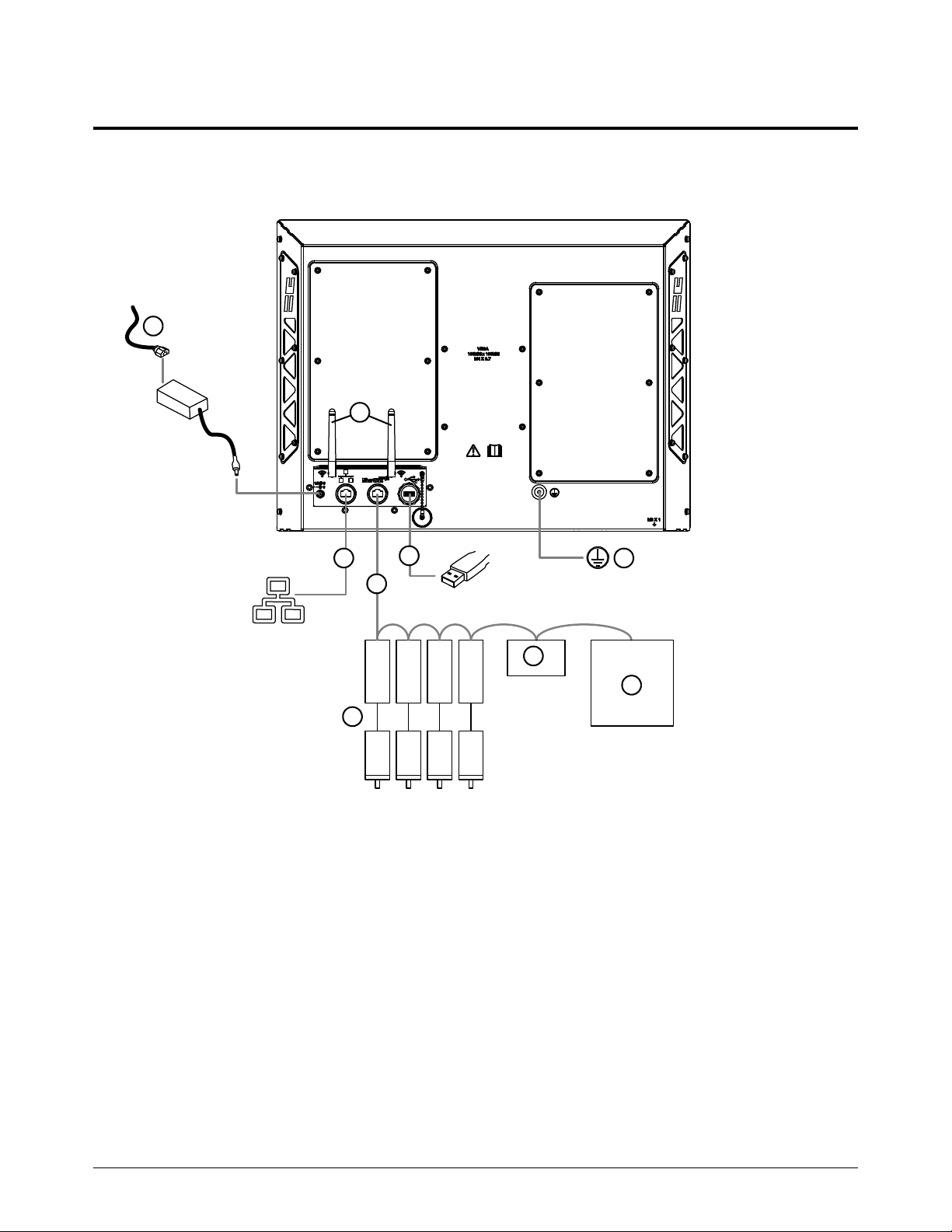
Specifications and Installation
1
1
2
3
5
6
7
8
9
4
1 External power supply and input power cord
2 Wireless antennas
3 LAN Ethernet cable
4 EtherCAT cable*
5 Drives and motors**
6 I/O module
7 Plasma power supply*
8 USB device***
9 EMI chassis ground
EDGE Connect TC (model number 090198)
Figure 4 – EDGE Connect TC system diagram
*
If you want to connect a Powermax or MAXPRO to an EDGE Connect CNC, use a discrete connection
through the drive I/O or an I/O module on the network.
**
Make sure that you can remove power from the drives separately from the CNC so that you can troubleshoot
network faults or errors if necessary. Refer to the drive manufacturer's documentation for instructions on drive
installation.
***
If you use a USB hub, use only 1 USB hub.
42 809340 Installation and Setup Manual EDGE Connect
Page 43

1
Before you begin
Ethernet cable
Specifications and Installation
If you plan to use wireless, you do not need an Ethernet cable for your
LAN connection.
This cable is customer supplied. Choose an Ethernet cable with the following specifications.
Specification Cat5e, F/UTP type cable, braid and foil shielding minimum
Maximum length 61 m (200 ft)
EtherCAT cable
Hypertherm sells EtherCAT cables, see External EtherCAT cables on page 337.
If you supply your own cables, choose EtherCAT cables that follow the Beckhoff
Type Cat5e, 2-pair, 4-wire, double-shielded
Wire Construction: Stranded tinned wire
Diameter: 0.75 mm (7 X 0.25 mm), 22 AWG
Insulation: Polyethylene, 1.5 mm (0.06 inch) diameter
Core Construction: Filler as central element
Layer 1: 4 wires, 2 pair
Sequence of colors: White, yellow, blue, orange
Layer 2: Plastic tape overlapped
Inner jacket: Thermoplastic copolymer, 3.9 mm (0.04 inch) diameter
Aluminum laminated foil overlapped
Shield: Braided, tinned copper wires, 0.13 mm (0.005 inch)
diameter, coverage about 85%, 4.7 mm (0.19 inch) diameter
®
specification.
Jacket Material: Polyurethane
Wall thickness: 0.9 mm (0.04 inch)
Outer diameter: 6.5 mm (0.26 inch) ± 0.2 mm (0.008 inch)
Maximum length 61 m (200 ft)
EDGE Connect Installation and Setup Manual 809340 43
Page 44

Specifications and Installation
1
External power supply and power cord
Hypertherm’s power supply is 5 A at 12 VDC or 60 W. It can be used to power the EDGE Connect
and the EDGE Connect TC. If you choose to buy your own external power supply and cord, use the
following specifications.
Input voltage 100 VAC to 240 VAC at 50 Hz/60 Hz
Output voltage 12 VDC ± 5%
External power supply type AC to DC switching
Minimum power supply capacity 60 W
External power supply to CNC connector Switchcraft
Screw lock (use only locking connectors)
5.5 mm (0.22 inch) outer diameter
2.5 mm (0.1 inch) inner diameter
9.5 mm (0.37 inch) long
®
760K, barrel type
EtherCAT drives
Install all the drives before you install your CNC. For a list of supported EtherCAT drives and I/O
modules, see the EtherCAT Devices Supported by EDGE Connect CNCs Application Note
(809660). Technical documentation is available at www.hypertherm.com/docs
.
44 809340 Installation and Setup Manual EDGE Connect
Page 45

1
EDGE Connect TC installation overview
These are the general steps to install the EDGE Connect TC. See
Figure 4 on page 42 for an example of how to install this system.
For more details, see Wiring Diagrams on page 339.
1. Mount the EDGE Connect TC.
For mounting dimensions see Mount the EDGE Connect
TC on page 48.
2. Install the wireless extensions, if necessary, and wireless
antennas.
3. Ground the EDGE Connect TC. See Ground the
EDGE Connect TC on page 53.
4. Connect the LAN Ethernet cable and EtherCAT cable to the EDGE Connect TC.
For LAN Ethernet cable requirements see Ethernet cable on page 43.
Specifications and Installation
For EtherCAT cable requirements see EtherCAT cable on page 43.
5. Connect the power to the EDGE Connect TC. For power supply requirements, see External
power supply and power cord on page 44.
6. Connect a USB keyboard and USB mouse to the CNC to make software setup easier. This
step is optional but strongly recommended.
7. Push the power button.
Turn off the CNC when not in use to prevent retained charge in the LCD
crystals.
EDGE Connect Installation and Setup Manual 809340 45
Page 46

Specifications and Installation
1
560.3 mm
(22.06 in.)
96.3 mm
(3.79 in.)
52.6 mm
(2.07 in.)
131.4 mm
(5.17 in.)
411.0 mm
(16.18 in.)
10 .7 k g
(23.6 lb)
495.3 mm
(19.5 in.)
EDGE Connect TC touchscreen specifications
Model number Size of screen Specifications
090198 495.3 mm (19.5 inches) • Projected capacitive touch (PCAP)
090185 469.9 mm (18.5 inches)
• 16:9 aspect ratio
• 1366 X 768 resolution
For more information about touchscreen resolution, see Monitor on
page 32.
EDGE Connect TC dimensions and weight
Figure 5 – Model number 090198 (495.3 mm/19.5 in. touchscreen)
46 809340 Installation and Setup Manual EDGE Connect
Page 47

Specifications and Installation
1
530.9 mm
(20.90 in.)
96.3 mm
(3.79 in.)
63.7 mm
(2.51 in.)
131.4 mm
(5.17 in.)
399.5 mm
(15.73 in.)
9.5 kg
(21.0 lb)
469.9 mm
(18.5 in.)
Figure 6 – Model number 090185 (469.9 mm/18.5 in. touchscreen)
EDGE Connect Installation and Setup Manual 809340 47
Page 48

Specifications and Installation
1
137.2 mm
(5.40 in.)
61.8 mm
(2.43 in.)
60.0 mm
(2.36 in.)
19.8 mm
(0.78 in.)
440 mm
(17.32 in.)
M6 X 1 mm threads
Maximum fastener depth is
10 mm (0.40 in.)
For access to EtherCAT and
12 VDC, for custom operator
consoles
The mounting pattern and dimensions are the same for model number 090198 (495.3 mm/19.5 in. touchscreen) and
090185 (469.9 mm/18.5 in. touchscreen).
Mount the EDGE Connect TC
You must mount the CNC.
The EDGE Connect TC can be mounted from the bottom on a flat surface, with a VESA bracket, or
with flush-mount brackets. Hypertherm sells mounting brackets. See Mounting options on
page 336.
EDGE Connect TC bottom mount
48 809340 Installation and Setup Manual EDGE Connect
Page 49

Specifications and Installation
1
183.8 mm
(7.24 in.)
10 0 m m
(3.94 in.)
10 0 m m
(3.94 in.)
M4 X 0.7 threads
Maximum fastener
depth is 10 mm
(0.40 in.)
The mounting pattern and dimensions are the same for model number 090198 (495.3 mm/19.5 in. touchscreen) and
090185 (469.9 mm/18.5 in. touchscreen).
EDGE Connect TC VESA mount
Hypertherm does not sell a VESA bracket. Use the dimensions below to buy a compatible bracket.
EDGE Connect Installation and Setup Manual 809340 49
Page 50

Specifications and Installation
1
Secondary enclosure
EDGE Connect TC flush-mount
Hypertherm sells a flush-mount bracket with screws. See Mounting options on page 336.
1. Select M4, M5, or M6 screws.
2. Use a CNC to cut the rectangle hole and screw holes. See Figure 8 on page 52 for dimensions.
The maximum panel thickness is 10 mm (0.4 inch).
The rectangle hole dimensions allow 0.51 mm (0.02 inch) nominal
clearance all around. You can adjust this clearance.
50 809340 Installation and Setup Manual EDGE Connect
Page 51

Specifications and Installation
1
561.3 mm
(22.10 in.)
411.50 mm
(16.20 in.)
586 mm
(23.07 in.)
Radius 5.3 mm
(0.21 in.)
Secondary enclosure
M4
300 mm
(11.81 in.)
M5
330 mm
(12.99 in.)
M6
360 mm
(14.17 in.)
20.20 mm
(0.79 in.)
35.20 mm
(1.39 in.)
50.20 mm
(1.98 in.)
3. Use the brackets and screws to mount the EDGE Connect TC in the panel.
Figure 7 – Dimensions for model number 090198 (495.3 mm/19.5 in. touchscreen)
EDGE Connect Installation and Setup Manual 809340 51
Page 52

Specifications and Installation
1
531.9 mm
(20.94 in.)
400.5 mm
(15.77 in.)
560 mm
(22.05 in.)
Radius 5.3 mm
(0.21 in.)
Secondary enclosure
M4
300 mm
(11.81 in.)
M5
330 mm
(12.99 in.)
M6
360 mm
(14.17 in.)
Figure 8 – Dimensions for model number 090185 (469.9 mm/18.5 in. touchscreen)
52 809340 Installation and Setup Manual EDGE Connect
Page 53

1
Ground the EDGE Connect TC
See Recommended grounding and shielding on page 55 for more information.
Specifications and Installation
The ground wire is customer supplied. The minimum ground wire size is 1.3 mm
1. Remove the screw from the rear of the CNC.
2
(16 AWG).
2. Put the ground wire terminal on the screw.
3. Tighten the screw.
4. Connect the ground wire to the EMI chassis ground.
EDGE Connect Installation and Setup Manual 809340 53
Page 54

Specifications and Installation
1
1
2
3
5
6
4
EDGE Connect TC rear I/O panel connector locations
1 Wireless antenna connector RP-SMA connector type
2 Female power-in connector 2.5 mm X 5.5 mm,12 VDC
3 Female RJ-45 connector For LAN, 10/100/1000 Mbps
4 Female RJ-45 connector For EtherCAT, 10/100/1000 Mbps
5 USB connector Hi-speed USB
6 EMI chassis ground M6 thread insert
54 809340 Installation and Setup Manual EDGE Connect
Page 55

1
Recommended grounding and shielding
Introduction
This section describes practices for grounding and shielding a plasma cutting system to minimize its
susceptibility to electromagnetic interference (EMI) (also known as noise). It also describes the
service ground, protective earth (PE) ground, and DC power ground. The diagram at the end of this
section shows these types of grounds in a plasma cutting system.
Specifications and Installation
Types of grounding
Service ground (also known as safety ground) is the grounding system that applies to the incoming
line voltage. It prevents a shock hazard to any personnel from any of the equipment or the cutting
table. It includes the service ground coming into the plasma system and other systems, such as the
CNC and the motor drives, as well as the supplemental ground rod connected to the cutting table.
In the plasma circuits, the ground is carried from the plasma system chassis to the chassis of each
separate console through the interconnecting cables.
Protective earth (PE) ground is the grounding system inside the electrical equipment. The PE
ground, which connects to the service ground, provides electrical continuity between the equipment
and the AC service.
The grounding practices in this section have been used on many
installations with excellent results, and Hypertherm recommends that
these practices be a routine part of the installation process. The actual
methods used to implement these practices may vary from system to
system, but should remain as consistent as possible. However, due to the
variation in equipment and installations, these grounding practices may
not succeed in every case to eliminate EMI problems. Hypertherm
recommends that you consult your local and national electrical codes to
make sure that the grounding and shielding practices that you use satisfy
the requirements for your location.
DC power ground (also known as cutting current ground or work) is the grounding system that
completes the path of the cutting current from the torch back to the plasma system. It requires that
the positive lead from the plasma system be firmly connected to the cutting table ground bus with a
properly sized cable. It also requires that the slats, on which the workpiece rests, make firm contact
with the table and the workpiece.
EMI grounding and shielding is the grounding system that limits the amount of EMI emitted by the
plasma and motor drive systems. It also limits the amount of EMI that is received by the CNC and
other control and measurement circuits. The grounding practices described in this section mainly
target EMI grounding and shielding.
EDGE Connect Installation and Setup Manual 809340 55
Page 56

Specifications and Installation
1
Grounding practices
1. Unless noted, for HPR or MAXPRO200 cutting systems, use cables with a minimum gauge of
13.3 mm
diagram with an HPR or MAXPRO200 cutting system on page 60. Unless noted, for XPR
cutting systems, use cables with a minimum gauge of 21.2 mm
ground cables shown in the Example grounding diagram with an XPR cutting system on
page 61.
2. The cutting table is used for the common, or star, EMI ground point and should have threaded
studs welded to the table with a copper bus bar mounted on them. A separate bus bar should
be mounted on the gantry as close to each motor as possible. If there are motors at each end of
the gantry, run a separate EMI ground cable from the far motor to the gantry bus bar. The gantry
bus bar should have a separate, heavy EMI ground cable 21.2 mm
table bus bar. The EMI ground cables for the torch lifter and the RHF or combined ignition/gas
connect console must each run separately to the table ground bus.
3. Inadequate grounding not only exposes operators to dangerous voltages, but inadequate
grounding also increases the risk of equipment failure and unnecessary downtime. Ideally a
ground should be zero ohms resistance, but field experience indicates under 1 ohm resistance
is satisfactory for most applications. Hypertherm recommends that you consult your local and
national electrical codes to make sure that the grounding and shielding practices that you use
satisfy the requirements for your location.
2
(6 AWG) (047040) for the EMI ground cables shown in the Example grounding
2
(4 AWG) (047031) for the EMI
2
(4 AWG; 047031) to the
4. A ground rod (a PE ground) that meets all applicable local and national electric codes must be
installed within 6 m (20 ft) of the cutting table. For HPR or MAXPRO200 cutting systems, the
PE ground must be connected to the cutting table ground bus bar using a minimum 13.3 mm
2
(6 AWG) green and yellow grounding cable (047121). For XPR cutting systems, the PE ground
must be connected to the cutting table ground bus bar using a minimum 21.2 mm
2
(4 AWG)
grounding cable (047031). Consult an electrician in your location to make sure that your
grounding meets all local and national electric codes.
5. For the most effective shielding, use the Hypertherm CNC interface cables for I/O signals, serial
communication signals, between plasma systems in multi-drop connections, and for
interconnections between all parts of the Hypertherm system.
6. All hardware used in the ground system must be brass or copper. While you can use steel studs
welded to the cutting table for mounting the ground bus, no other aluminum or steel hardware
can be used in the ground system.
7. AC power, PE, and service grounds must be connected to all equipment according to local and
national codes.
8. For a system with a remote high frequency (RHF) console or combined ignition/gas connect
console, the positive, negative, and pilot arc leads should be bundled together for as long a
distance as possible. The torch lead, work lead, and the pilot arc (nozzle) leads may be run
parallel to other wires or cables only if they are separated by at least 150 mm (6 inches). If
possible, run power and signal cables in separate cable tracks.
56 809340 Installation and Setup Manual EDGE Connect
Page 57

Specifications and Installation
1
9. For a system with a RHF console or combined ignition/gas connect console, Hypertherm
recommends that you mount this console as close as possible to the torch. This console also
must have a separate ground cable that connects directly to the cutting table ground bus bar.
10. Each Hypertherm component, as well as any other CNC or motor drive cabinet or enclosure,
must have a separate ground cable to the common (star) ground on the table. This includes the
ignition/gas connect console, whether it is bolted to the plasma system or to the cutting table.
11 . For HPR or MAXPRO200 cutting systems, the metal braided shield on the torch lead must be
connected firmly to the ignition/gas connect console and to the torch. It is recommended to be
electrically insulated from any metal and from any contact with the floor or building. The torch
lead can be run in a plastic cable tray or track, or covered with a plastic or leather sheath.
12. For XPR cutting systems, the coupler on the pilot arc and coolant hose set assembly must be
connected firmly to the gas connect console and torch connect console collars. Make sure to
tighten the clamp. The collar on the torch lead must be connected firmly to the torch sleeve.
Make sure to tighten the clamp. Connect a ground lead (10 AWG) to the flat terminal on the
torch mounting sleeve.
13. The torch holder and the torch breakaway mechanism – the part mounted to the lifter, not the
part mounted to the torch – must be connected to the stationary part of the lifter with copper
braid at least 12.7 mm (0.5 inches) wide. A separate cable must run from the lifter to the gantry
ground bus bar. The valve assembly should also have a separate ground connection to the
gantry ground bus bar.
14. If the gantry runs on rails that are not welded to the table, then each rail must be connected with
a ground cable from the end of the rail to the table. The rail ground cables connect directly to
the table and do not need to connect to the table ground bus bar.
15. If you are installing a voltage divider board, mount it as closely as possible to where the arc
voltage is sampled. One recommended location is inside the plasma system enclosure. If a
Hypertherm voltage divider board is used, the output signal is isolated from all other circuits. The
processed signal should be run in twisted shielded cable (Belden 1800F or equivalent). Use a
cable with a braided shield, not a foil shield. Connect the shield to the chassis of the plasma
system and leave it unconnected at the other end.
16. All other signals (analog, digital, serial, and encoder) should run in twisted pairs inside a
shielded cable. Connectors on these cables should have a metal housing. The shield, not the
drain, should be connected to the metal housing of the connector at each end of the cable.
Never run the shield or the drain through the connector on any of the pins.
EDGE Connect Installation and Setup Manual 809340 57
Page 58
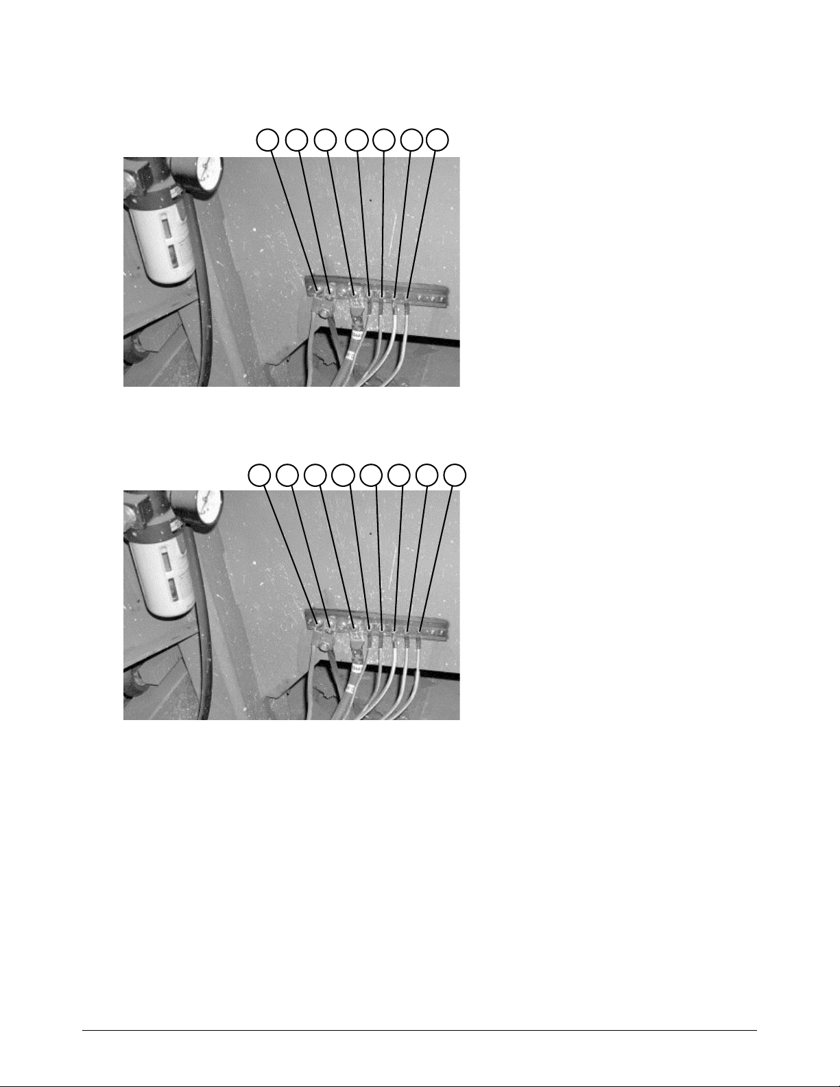
Specifications and Installation
1
1 Gantry ground bus
2 Ground rod
3 Plasma system lead (+)
4 RHF console (if applicable, not on all
systems)
5 CNC enclosure
6 Torch holder
7 Plasma system chassis
1 2 3
4
5 6 7
1 Gantry ground bus
2 Ground rod
3 Plasma system lead (+)
4 Gas connect console
5 CNC enclosure
6 Torch holder
7 Plasma system chassis
8 Torch connect console
1 2 3
4
5 6
7 8
The following picture shows an example of a cutting table ground bus with an HPR or
MAXPRO200 cutting system. The components shown here may differ from your system.
The following picture shows an example of a cutting table ground bus with an XPR cutting system.
The components shown here may differ from your system.
58 809340 Installation and Setup Manual EDGE Connect
Page 59

Specifications and Installation
1
1 Cable to the cutting table ground bus
2 Ground cables from components on the
gantry
1 2
The following picture shows an example of a gantry ground bus. It is bolted to the gantry, close to
the motor. All of the individual ground cables from the components mounted on the gantry connect
to the bus. A single heavy cable then connects the gantry ground bus to the table ground bus.
EDGE Connect Installation and Setup Manual 809340 59
Page 60

Specifications and Installation
1
Chassis and RFI ground
AC earth ground (PE)
1
2
3
4
5
6
7
8 9
10
11
12
13
1 Cutting table
2 Gantry
3 Plasma system
4 Table ground bus bar
5 Gantry ground bus bar
6 Torch height control lifter (ArcGlide, Sensor THC,
Sensor PHC, or other)
7 RHF console (not on all systems). Connect to
table ground bus bar.
8, 9 System-specific component such as metering
console, gas console, or selection console
10 CNC chassis
11 Torch height control module
(ArcGlide, Command THC)
12 System-specific component such as a cooler or
chiller
13 DC power ground
Example grounding diagram with an HPR or MAXPRO200 cutting system
60 809340 Installation and Setup Manual EDGE Connect
Page 61

1
Example grounding diagram with an XPR cutting system
Chassis and EMI ground
Service ground
1
2
3
4
5
6
7
8
9
10
11
PE earth ground
1 Cutting table
2 Gantry
3 Plasma system
4 Table ground bus bar
5 Gantry ground bus bar
6 Torch height control lifter
7 Torch connect console
8 CNC controller
9 Torch height control module
10 Gas connect console. Connect to table ground
bus bar.*
11 DC power ground (work)
* The ignition console is integrated into the gas connect
console for XPR cutting systems.
Specifications and Installation
EDGE Connect Installation and Setup Manual 809340 61
This example is based on practices in North America. Other regions can
have different local or national electrical codes. Hypertherm recommends
that you consult your local and national electrical codes to make sure that
the grounding and shielding practices that you use satisfy the
requirements for your location.
Page 62
Specifications and Installation
1
s
Symbols and marks
Your product may have one or more of the following marks on or near the data plate. Because of differences
and conflicts in national regulations, not all marks are applied to every version of a product.
S mark
The S mark indicates that the power supply and torch are suitable for operations carried out in
environments with increased hazard of electrical shock according to IEC 60974-1.
CSA mark
Products with a CSA mark meet the United States and Canadian regulations for product safety.
The products were evaluated, tested, and certified by CSA-International. Alternatively, the product
may have a mark by one of the other Nationally Recognized Testing Laboratories (NRTL)
accredited in both the United States and Canada, such as UL or TÜV.
CE mark
The CE marking signifies the manufacturer’s declaration of conformity to applicable European
directives and standards. Only those versions of products with a CE marking located on or near
the data plate comply with European Directives. Applicable directives may include the European
Low Voltage Directive, the European Electromagnetic Compatibility (EMC) Directive, the Radio
Equipment Directive (RED), and the Restriction of Hazardous Substances (RoHS) Directive.
See the European CE Declaration of Conformity for details.
Eurasian Customs Union (CU) mark
CE versions of products that include an EAC mark of conformity meet the product safety and
EMC requirements for export to Russia, Belarus, and Kazakhstan.
GOST-TR mark
CE versions of products that include a GOST-TR mark of conformity meet the product safety and
EMC requirements for export to the Russian Federation.
RCM mark
CE versions of products with a RCM mark comply with the EMC and safety regulations required
for sale in Australia and New Zealand.
CCC mark
The China Compulsory Certification (CCC) mark indicates that the product has been tested and
found compliant with product safety regulations required for sale in China.
UkrSEPRO mark
The CE versions of products that include a UkrSEPRO mark of conformity meet the product safety
and EMC requirements for export to the Ukraine.
Serbian AAA mark
CE versions of products that include a AAA Serbian mark meet the product safety and
EMC requirements for export to Serbia.
RoHS mark
The RoHS mark indicates that the product meets the requirements of the European Restriction of
Hazardous Substances (RoHS) Directive.
62 809340 Installation and Setup Manual EDGE Connect
Page 63

Operate
Phoenix Soft Op Con
When you turn on the CNC, the Phoenix software and the software operator console (Soft Op Con)
open. Before using Phoenix, you must click OK on a dialog window to agree to Hypertherm’s Terms
of Use.
Figure 9
Phoenix is the core software interface for operating the CNC, and is common across all Hypertherm
CNCs. The Soft Op Con is a fully integrated part of Phoenix. The standard Hypertherm
Soft Op Con, shown in Figure 9, comes with the EDGE Connect and EDGE Connect TC CNCs.
EDGE Connect Installation and Setup Manual 809340 63
Page 64

Operate
2
2
1
1
2
Cutting system manufacturers can create their own custom software operator consoles using the
Phoenix application programmer interface (API). If your cutting system has a custom software
operator console, contact your cutting system manufacturer or see their documentation for more
information. See also Automatically open a custom software operator console on page 70.
Operate Phoenix
In addition to the information in this manual, the Phoenix Help provides details on how to operate
the Phoenix software. Phoenix Help is available for each screen in Phoenix. For more information,
see Phoenix Help and technical documentation on page 73.
The buttons in Phoenix screens are called soft keys.
Some soft keys go to particular screens, and some soft keys do a particular action. The soft keys
that show on a screen change based on installed components, enabled features, Phoenix setup
options, passwords, and user levels (beginner, intermediate, or advanced).
64 809340 Installation and Setup Manual EDGE Connect
This manual assumes the CNC is in advanced user level mode and shows
all features.
Page 65

2
Operate the standard Hypertherm Soft Op Con
1
2 3
4
5
1
1 Station control tab (shown)
2 Manual motion tab
3 Screen capture and live video tab
4 Information tab
5 Program control (always shows)
The Soft Op Con can replace a hardware operator console. With an EDGE Connect TC, the
Soft Op Con and the hardware operator console can be used together. For example, pressing Start
in the Soft Op Con is the same as pressing the Start button on the hardware operator console.
Operate
Cutting system manufacturers can create their own custom software
operator consoles using the Phoenix application programmer interface
(API). If your cutting system has a custom software operator console,
contact your cutting system manufacturer or see their documentation for
more information.
The following sections explain each part of the Soft Op Con.
EDGE Connect Installation and Setup Manual 809340 65
Page 66

Operate
2
1
2 3
4 5
1 Station number
• As defined on the Station Configuration
screen (stations 1 – 8) or the Digital I/O
screen (stations 9 – 20)
2 Station status
• Enabled (green)
• Disabled (red)
3 Disable station key
• Press to disable the station (green when
selected)
4 Manual mode key
• Press to operate the station in manual
mode (green when selected)
5 Program (automatic) mode key
• Press to operate the station in program
mode (green when selected)
1
32
1 Program speed (if speed pots are enabled on
the Analog I/O screen)
• Slide left for slower program speed
• Slide right for faster program speed
2Start cutting key
• Press to start cutting
3 Stop cutting key
• Press to stop cutting
Station control tab
Program control
66 809340 Installation and Setup Manual EDGE Connect
Page 67

2
Manual motion tab
1
2
3
4
5
4
These soft keys control all of the stations that are currently enabled.
Operate
1Move speed (if speed pots are enabled on the Analog I/O screen)
• Slide left for slower move speed
• Slide right for faster move speed
2 Latch manual keys key
• Press to turn ON latch manual keys (if enabled in the Special Setups screen)
• Press again to turn OFF latch manual keys
3 Directional jog keys
• Press an arrow key to move in that direction (if latch manual keys is enabled and ON)
• Press and hold an arrow key to move in that direction (if latch manual keys is OFF)
4 Raise torch key
• Press and hold to raise the torch or tool
5 Lower torch key
• Press and hold to lower the torch or tool
EDGE Connect Installation and Setup Manual 809340 67
Page 68

Operate
2
1
3
5
4
2
6
7
8
(In use)
Screen capture and live video tab
1 Screen capture and live video* view
This area shows the current screen capture or live video.*
2 Select video source
If two or more video cameras are installed, choose a camera in the drop-down menu.
3
Start or Pause live video
4 Capture the CNC screen, including Phoenix and the Soft Op Con.
This button appears green while in use.
5 Clear screen capture/ Stop live video
6 Refresh video camera options
7 Enlarge image or video in a new window
• Click and drag the new window, such as for display on an external monitor (if installed).
• To close the new window, click on the X in the upper-right corner of the window.
8 Save screen capture
Open the Save As menu and save your screenshot as a file. Videos are not recorded on the CNC.
* Live video is supported if you have one or more supported USB video cameras installed. Video cameras are supplied by your
cutting system manufacturer.
68 809340 Installation and Setup Manual EDGE Connect
Page 69

2
Information tab
1
Operate
1 Soft Op Con version
• Shows the version of the Soft Op Con on the
CNC
EDGE Connect Installation and Setup Manual 809340 69
Page 70

Operate
2
Automatically open a custom software operator console
Cutting system manufacturers can create their own custom software operator consoles using the
Phoenix application programmer interface (API). By default, the EDGE Connect Launcher
automatically opens the standard Hypertherm Soft Op Con when an operator turns on the CNC. To
automatically open the custom software operator console instead, modify the EDGE Connect
Launcher.
Before you begin
Make sure that the executable (.exe) files for the custom software operator console
application are saved in the C:\Phoenix folder on the CNC. Typically there is one .exe file
for the upper part of the Soft Op Con and one .exe file for the lower part of the
Soft Op Con.
Connect a USB keyboard and USB mouse to the CNC.
Modify the EDGE Connect Launcher
1. Close all the EDGE Connect software on the CNC.
a. Click anywhere in the Main screen of Phoenix, and then press Alt+F4 to exit Phoenix.
b. Click anywhere in the upper part of the Hypertherm Soft Op Con, and then press Alt+F4 to
exit the upper part of the Hypertherm Soft Op Con.
c. Click anywhere in the lower part of the Hypertherm Soft Op Con, and then press Alt+F4 to
exit the lower part of the Hypertherm Soft Op Con.
2. Click the Windows Start button and then click File Explorer.
3. In the C:\Phoenix folder, double-click the steps.json file.
4. To replace the upper part of the Hypertherm Soft Op Con, do the following in the steps.json file:
The steps.json file should automatically open in Notepad. If it does not,
open Notepad and then open the steps.json file.
70 809340 Installation and Setup Manual EDGE Connect
Page 71

2
Figure 10
Operate
a. Next to StepName, delete SoftOpCon.
b. Type the name of the upper part of the custom software operator console.
c. Next to StepDesc, delete Starting Hypertherm Soft Op Con.
d. Type the text you want to appear while the custom software operator console opens.
e. Next to StepPath, delete C:\\Phoenix\\SoftOpCon.exe.
f. Type the absolute path of the executable (.exe) file for the upper part of the custom software
operator console. For example: C:\\Phoenix\\CustomSoftOpCon.exe.
5. To replace the lower part of the Hypertherm Soft Op Con, do the following in the steps.json file:
Only delete the specified characters. Do NOT delete quotation marks,
commas, brackets, or other existing characters from the file.
EDGE Connect Installation and Setup Manual 809340 71
Page 72

Operate
2
Figure 11
a. Next to StepName, delete MinReqOpCon.
b. Type the name of the lower part of the custom software operator console.
c. Next to StepDesc, delete Starting Hypertherm Soft Op Con.
d. Type the text you want to appear while the custom software operator console opens.
a. Next to StepPath, delete C:\\Phoenix\\MinReqOpCon.exe.
b. Type the absolute path of the executable (.exe) file for the lower part of the custom software
operator console. For example: C:\\Phoenix\\CustomMinReqOpCon.exe.
6. On the File menu in Notepad, click Save and then close the steps.json file.
7. Click the Windows Start button and then click EDGE Connect Launcher to open Phoenix and
the custom Soft Op Con.
Only delete the specified characters. Do NOT delete quotation marks,
commas, brackets, or other existing characters from the file.
To get support using your custom Soft Op Con, contact your cutting
system manufacturer.
72 809340 Installation and Setup Manual EDGE Connect
Page 73

2
Phoenix Help and technical documentation
Phoenix Help gives details on how to operate the Phoenix software. Phoenix
Help is available for each screen in Phoenix.
Choose the Help soft key to see information about each screen.
Operate
To close the Help window, press the X in the upper right corner.
EDGE Connect Installation and Setup Manual 809340 73
Page 74

Operate
2
Hypertherm also provides tips and solutions for common issues to help
improve cut quality.
Choose the Cutting Tips soft key for this information.
To close the cutting tips, choose the OK soft key.
74 809340 Installation and Setup Manual EDGE Connect
Page 75

2
In addition, Hypertherm provides technical documentation for the CNC and
any other installed Hypertherm components of your cutting system.
Choose the Technical Documentation soft key to get this documentation.
Figure 12
Operate
The EDGE Connect Installation and Setup Manual opens automatically.
Soft keys for all the technical documentation available for installed components appear at the
bottom of the screen. For example, Figure 12 shows an EDGE Connect Manual soft key and an
HPR Manual soft key.
EDGE Connect Installation and Setup Manual 809340 75
Page 76

Operate
2
To see the contents of a manual, choose the Show Bookmarks soft key. Choose a topic in the list
to go to that page in the manual.
To do a full-text search, press Ctrl + F.
76 809340 Installation and Setup Manual EDGE Connect
Page 77
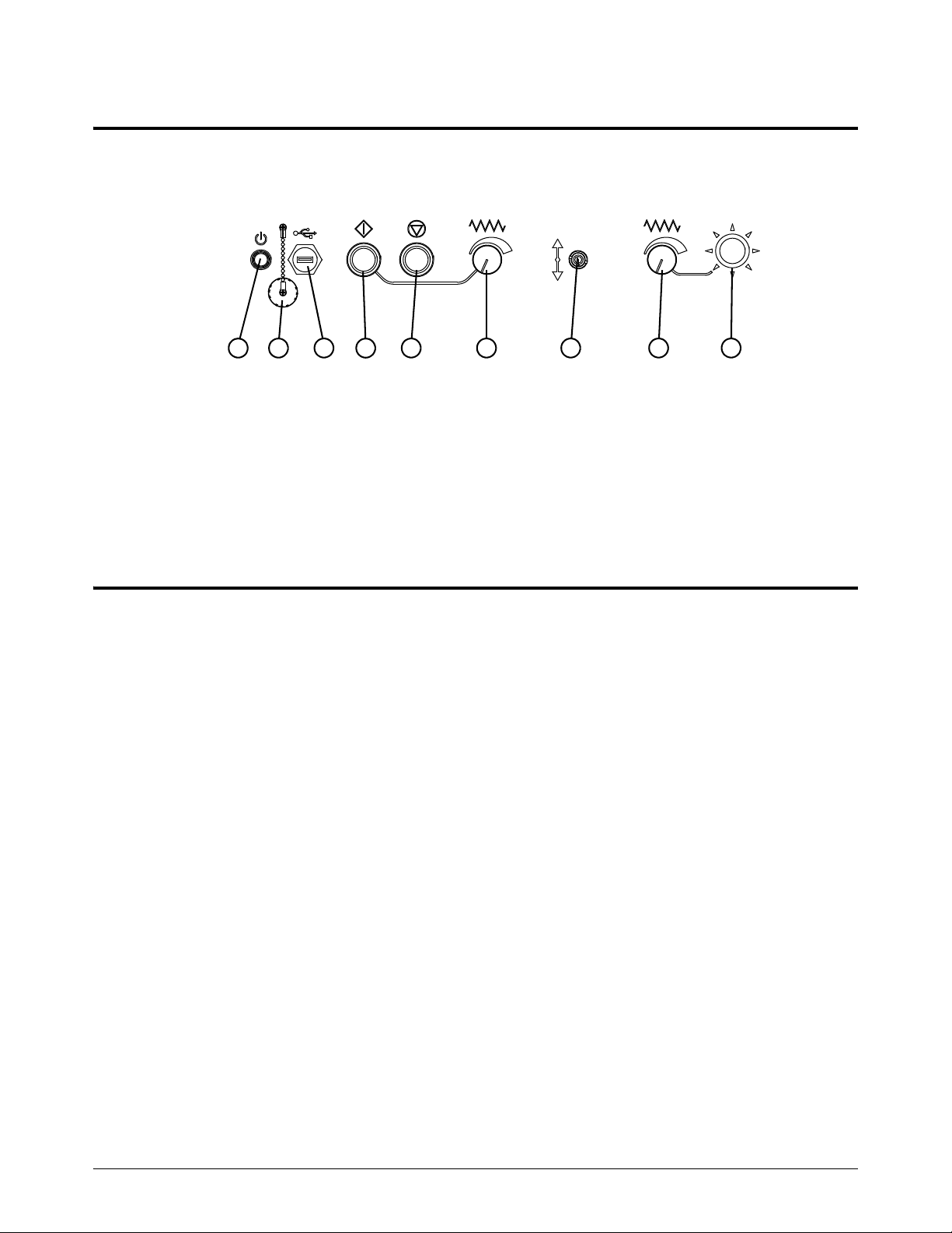
2
Operate the EDGE Connect TC hardware operator console
12 3
5
6
8
9
4
7
1 Power button
2 USB connector cover with chain
3 Female USB connector
4 Start button (green)
5 Stop button (red)
6 Program speed potentiometer
7 Raise or lower station
8 Manual speed potentiometer
9 Joy stick
The EDGE Connect TC comes with a hardware operator console.
Operate
Operate the touchscreen
The EDGE Connect supports a touchscreen. The EDGE Connect TC comes with a touchscreen.
Touch the window controls and fields to enter data into the software. Any field that requires data
input automatically shows an on-screen keypad when you tap it twice.
Touchscreens, drops of water, and unintended motion
Drops of water can be a safety concern if you install the EDGE Connect on a water table. If water
gets onto the touchscreen, the drops can activate a jog key and cause unintended motion on the
table. Unintended motion can cause dangerous conditions for the operator and other people,
damage to machinery, or faults in cutting. To prevent unintended motion:
Dry your hands completely before you use the touchscreen.
Install the CNC so that the touchscreen has protection from water splashes.
If water could get on the touchscreen, do not display the jog keys in the Watch Window or
the software operator console (Soft Op Con).
Hypertherm recommends enabling the Ready to Move? dialog if there are
any concerns that water could get onto the EDGE Connect touchscreen.
The Ready to Move? dialog can be enabled on the Special Setups
screen (Setups > Password > Special Setups).
For additional information, contact your nearest Hypertherm office listed in the front of this manual.
EDGE Connect Installation and Setup Manual 809340 77
Page 78

Operate
2
Optional keyboard and mouse
You can use a USB-connected keyboard and mouse to enter information and navigate the
CNC software.
78 809340 Installation and Setup Manual EDGE Connect
Page 79

Machine Stop Strategies and Table Hardware
Machine stop strategies
Phoenix provides several options to ramp down motion to stop the cutting system in the case of a
fault or error condition or an emergency. The option you choose depends on the mechanical design
of the cutting system and your national and local electrical and safety codes. Consult your
regulatory authority to make sure that your cutting system meets all codes.
Use the following information to implement the machine stop strategies that meet the needs of your
cutting system and the electrical and safety codes for your location.
How the CNC stops motion
Types of stops: Program stop/pause, Fast stop, and Fault ramp
Safety circuit example
About drive enable signals
About the Drive Enable output and Drive Disabled input
How the CNC enables and disables the drives
Inputs and outputs provided by the CNC
EDGE Connect Installation and Setup Manual 809340 79
Page 80

Machine Stop Strategies and Table Hardware
3
Drive Enable
output ON
Servo command
voltage = n V
(motion)
Drive Enable output OFF
Home position (if homing used)
is retained
OFF or 0 V
Fast Decel Rate
Servo command voltage to 0
(motion stopped)
Time
Fast Stop input turns ON
How the CNC stops motion
Program pause/stop (non-urgent stop)
A non-urgent stop is used to pause or stop cutting or trialing. The CNC brings the machine to a
stop using the acceleration rate set for the program speed or manual move speed at which the
cutting system is moving.
Fast stop/fast deceleration (urgent stop)
Fast stop brings all drives to an abrupt stop when a fault occurs and then disables the drives. A fast
stop occurs when an operator activates the fast stop input or under these fault conditions:
Torch Collision (if Fast Decel is selected on the I/O setup screen)
X and Y overtravel inputs are activated
Software overtravel limits are activated (if Fast Decel is selected)
Fast stop should be used when safety is not a factor. The deceleration rate is entered on the
Speeds screen in the Fast Deceleration field. The table’s home position (if homing is used) and
program position information are retained.
Figure 13 – Fast stop/fast deceleration
Fault ramp
Fault Ramp brings all drives to an abrupt stop and then disables the drives when one of these faults
occur:
80 809340 Installation and Setup Manual EDGE Connect
Torch Collision (if Fault Ramp is selected on the I/O setup screen)
X and Y overtravel inputs are activated
Software overtravel limits are activated (if Fault Ramp is selected)
Page 81

Machine Stop Strategies and Table Hardware
3
Drive Enable
output ON
Servo command
voltage = n V
(motion)
Drive Enable output OFF
Home position (if homing used) and
program position NOT retained
OFF or 0 V
Servo command voltage to 0
(motion stopped)
Time
Hardware overtravel switch
turns ON
Fault Ramp Time
0.1 – 2 seconds
The deceleration rate uses the Fault Ramp Time entered on the Axis screens and disables the drives
when the Fault Ramp time expires. The table’s home position (if homing is used) is not retained and
the table will need to be homed. An exception is a torch collision, which does not require homing
again.
To meet immediate-disable safety standards, the Fault Ramp Time must be set to 0 seconds. When
the Front Panel E-Stop input is activated, the drives will be disabled immediately. With no resistance
from the motors, there is a potential for the table gantry to coast or move uncontrollably. How far the
cutting machine coasts depends on the gantry weight, mechanics, the speed of the gantry when the
Front Panel E-Stop input is activated, and the amount of friction present.
If a coasting gantry is a concern, adjust the Fault Ramp Time value to bring the gantry to a controlled
stop before the drives are disabled. The available range for Fault Ramp Time is between 0.1 and 2
seconds.
In general, larger gantries require a longer Fault Ramp Time to stop the cutting system safely.
Shorter Fault Ramp Times result in faster, or immediate, stop times which can cause damage to the
cutting machine and the drive mechanics. Controlling the gantry to a stop may not meet certain
safety regulations and may not meet other local codes or standards. Consult local safety regulations
for a complete understanding of the requirements for your system.
The CNC is capable of running with software overtravel limits that are based on position. When
enabled, this feature lets you select Fault or Fast Decel when active. Fault operates as hardware
switches with immediate fault. Fast Decel uses the fast deceleration value to ramp down motion.
Figure 14 – Fault Ramp
EDGE Connect Installation and Setup Manual 809340 81
Page 82

Machine Stop Strategies and Table Hardware
3
Emergency stop (E-stop) and Fast Stop compared
Fast Stop
Use the Fast Stop input when you want an urgent stop. DO NOT use the Fast Stop input for an
E-stop. Connect the Fast Stop input to a separate switch on the operator console. When this input
activates, the CNC decelerates motion for 1 second using the Fast Deceleration Rate on the
Speeds screen, then turns off the individual drive enable signals and the Drive Enable output. The
CNC retains position information so that you can restart the cutting job after clearing the condition
that caused you to stop the system.
If the Fast Stop input is removed in less than 1 second, the drives may
remain enabled.
Emergency stop
An emergency stop, or E-stop, is a physical switch on the cutting system or on a CNC custom
operator console. The design and implementation of an E-stop switch and circuit depends on
national and local electrical and safety codes.
The EDGE Connect/EDGE Connect TC CNC provides an input called Front Panel E-Stop for use
when designing an E-stop circuit. When this input activates, the CNC turns off the individual drive
enable signals and the Drive Enable output. The CNC also erases all position information from
memory and requires that you re-home the cutting system. The CNC displays the status message
Emergency Stop Active when the Front Panel E-stop input activates.
In Phoenix, you can enter a fault ramp time for each axis. The Fault Ramp Time delays the CNC from
turning off the Drive Enable output so that power is maintained to the drives briefly (0.1 to 2
seconds) to stop the gantry without damage to the mechanics.
Normally local safety codes require AC power to be removed immediately from the drives. In this
case, enter 0 for the fault ramp time for each axis.
CAUTION
Using a 0-second Fault Ramp Time could result in the gantry coasting, which can damage the
cutting machine and the drive mechanics. Controlling the gantry to a stop may not meet certain
safety codes and may not meet other local codes or standards. Consult local safety regulations
for a complete understanding of the requirements for your system.
82 809340 Installation and Setup Manual EDGE Connect
Page 83

Machine Stop Strategies and Table Hardware
3
Enable the cutting machine after a power cycle or stop
After you turn ON the cutting machine and after an emergency or urgent stop, one or more error
messages like the following appears.
These error messages are remaining from the interruption in EtherCAT network communications
when the CNC was turned off or motion stopped. You need to re-enable the drives. Choose
Manual to close each message. Phoenix continues to start the EtherCAT network.
If the error messages continue to appear, another method may be necessary. This is because how
you re-enable the cutting machine depends on the wiring of the drives, the machine’s safety circuit,
the machine’s reset mechanisms, the disable input assigned in the CNC, and the timing of the
CNC’s enable logic.
The following is another example sequence of re-enabling the drives. (The state of the machine is:
E-stop depressed, no AC power to the drives, and the disable input is active to the CNC.) Turn ON
the CNC and wait for the network to establish communications.
Deactivate the disable input to the CNC (Drive Disabled, Front Panel E-stop, or Fast Stop). Often
this is accomplished by a reset mechanism or push-button, depending on the operator console and
the drive box safety circuit.
After the input is deactivated, the CNC attempts to re-enable the drives for up to 2 seconds. After
2 seconds, the CNC stops trying. The drives must be in stand-by mode or the attempt fails after
2 seconds. If the CNC doesn’t succeed in re-enabling the drives automatically, you can re-enable
the drives manually by choosing the Setups > Enable Control soft key.
EDGE Connect Installation and Setup Manual 809340 83
Page 84

Machine Stop Strategies and Table Hardware
3
Main contactor
Customer-supplied components for
safety circuit
(within dotted lines)
E-Stop
push button switch
Normally Closed
Front Panel E-stop (input to CNC)
AC power to drives
Drive Disabled (input to CNC)
Drive Enable (output from CNC)
Power On/Reset
Momentary switch,
Normally Open
Safety circuit example
The following drawing shows a simplified example of the components and I/O of a cutting system
safety circuit.
The drawing is an example only. There are other ways to create a safety
circuit. For instance, this example does not use the Safe Torque Off (STO)
that is available on certain drives.
The CNC follows this sequence of operations:
Power to the drives requires:
Front Panel E-stop input or Fast Stop input must be OFF, and
Drive Enable output must be ON, then
AC power can flow to the drives through the main contactor. A switch connects the
main contactor to the safety circuit.
Figure 15 – Safety circuit logic example
When the E-stop push button is engaged, the Drive Disabled input turns ON and the Drive Enable
output turns OFF. As long as Drive Disabled is ON, AC power is removed from the drives and no
motion can occur. Use both of these inputs.
The Front Panel E-stop input indicates the E-stop switch is engaged. Drive Disabled indicates the
safety circuit has not been reset. You have to re-enable with a push-button reset that turns off the
Drive Disable input and maintains that status until the Drive Enable output becomes active.
After the stop condition is cleared, the Power On/Reset switch is used to restore the I/O and power
to the drives.
84 809340 Installation and Setup Manual EDGE Connect
Page 85

3
Drive enable signals
When the CNC turns ON, with no safety inputs active (Drive Disabled, Fast Stop, or Front Panel
E-stop), it immediately enables the drives.
Each axis has an axis enable signal. Phoenix activates this signal when it turns ON the Drive
Enable # status signal where the # is the axis number. When the drives are wired in series, these
signals activate or deactivate at the same time. When the drives are wired in parallel, the signals
activate and deactivate in succession. After the Drive Enable bit is activated for each axis in the
cutting system, the CNC turns ON the Drive Enable output.
In the Setups > I/O screen, select whether the drive enable signals should be activated in series or
independently. If a fault or error occurs, drives in series all complete their ramp times before the
drives are disabled. Drives that are wired in parallel or independently each disable at the end of the
Fault Ramp Time.
Drive Enable output
A Drive Enable output must be assigned in the CNC and wired into the cutting system safety circuit.
This output turns off after the individual drive enable signals turn off. When you require a controlled
stop to the cutting system where motion ramps down before the drives are disabled, you want to
include the Drive Enable output as part of your safety circuit logic and drive wiring scheme.
Machine Stop Strategies and Table Hardware
A 2-second delay is required before the Drive Enable output turns on. The
operator may need to press and hold the reset switch for 2 seconds.
Drive Disabled input
Wire this input to the drive box safety circuit. The CNC doesn’t know if a drive is disabled unless the
Drive Disabled input is wired into the safety circuit. If a safety condition occurs, the Drive Disabled
input opens (it is Normally Closed) and the CNC cannot enable the drives until the Drive Disabled
input is closed again.
In a cutting system using an EDGE Connect CNC, messaging on the network tells the CNC
whether or not the drives are enabled. If one or more drives are not enabled then the CNC changes
to Control Disabled state. When the issue is resolved, the operator can toggle the Enable Control
soft key in the Setups screen. This allows the CNC to re-enable the drives.
Hardware overtravel limits
Select whether the cutting system will be using hardware overtravel switches. If hardware overtravel
switches are used, the CNC will disable feedback and display an error message if the inputs
become active. It is recommended that hardware overtravel switches be installed.
EDGE Connect Installation and Setup Manual 809340 85
Page 86

Machine Stop Strategies and Table Hardware
3
Gantry
1
2 354
Software travel limits
If Software Overtravels are enabled, the user is prompted for the minimum and maximum travel of
the cutting machine.
A software travel limit (also called a software overtravel) is a position on the axis that can be reached
before the system contacts a hardware limit switch or hard stop. Figure 16 on page 86 shows
measurements from an example system with a gantry that has 154 inches (3,912 mm) of travel on
the Transverse axis between the overtravel switches.
The gantry travel distance of 154 inches (3,912 mm) also equals the
Table Size X dimension on the Machine Setups screen (Setups >
Password > Machine Setups).
For software travel limits to work correctly, the cutting system must first be
homed so that the CNC can determine the absolute home position.
Figure 16
86 809340 Installation and Setup Manual EDGE Connect
Page 87

3
Home switches
1 Gantry distance between hardware overtravel
switches 154 inches (3,912 mm)
2 X- overtravel switch at 0 mm (0 inches) (this
equals the Absolute Home position on the X
axis setup screen). Add a hard stop to the left
of . There needs to be enough space to stop
without breaking your hard stop.
2
3 X+ overtravel switch at 154 inches
(3,912 mm) (when the Absolute Home
position is 0 mm [0 inches])
4 Software minimum travel limit at 3 inches
(76 mm) to stop motion before contact with
the hardware overtravel switch.
5 Software maximum travel limit at 151 inches
(3,835 mm) to stop motion before contact with
the hardware overtravel switch.
The Home parameter is used to activate use of the Home feature. Depending on configuration, the
table may be Homed to either a designated Home Switch or an Overtravel Switch.
The Home feature is used to set a known absolute physical position location on the cutting table.
This is used for referencing future manual Go to Home and other motion commands. This is
generally performed through activation of a home switch positioned on the appropriate axis, giving it
a known physical location.
Machine Stop Strategies and Table Hardware
When you enter a homing command, the CNC moves the axis toward the home switches at the Fast
Home Speed until the switches activate. Once the switches activate, motion stops and then the axis
moves in the opposite direction of the switch at the Slow Home Speed. The moment that the switch
deactivates, the CNC resets the axis position to the absolute home position. Motion then continues
for the Home Offset distance. When motion stops, the position is saved as the Home reference.
The Absolute Home Position defines the position of the axis when the Home Limit Switch
turns off or Marker Pulse is detected.
The Home Offset Distance allows the user to set an offset distance from the Home Limit
Switch.
Home Direction determines which direction the axes will travel during phase one of the
homing sequence.
The Axes Home Position is the position of the axes when homing is complete.
Use Marker Pulse, when enabled, assigns the absolute home position at the instant the
marker pulse is detected. It is recommended that the Marker Pulse be used for optimal
homing repeatability.
The Dual Gantry Home switch offset value needs to change when the home switch is moved
or replaced. Phoenix aligns the Rail and Dual Gantry axis based on the old Dual Gantry
Home switch offset value. When you zero the switch offset value to measure the new switch
offset value, Phoenix returns the wrong measured value because the original switch offset
value is still being applied. There are 2 ways to fix this issue.
EDGE Connect Installation and Setup Manual 809340 87
Zero the switch offset value and shutdown and re-start Phoenix.
Zero the switch offset value, disable and re-enable the control and then measure and
enter the new switch offset value. A simple solution in Phoenix is to disable and then
re-enable the axis each time the Dual Gantry Home switch offset value changes.
Page 88

Machine Stop Strategies and Table Hardware
3
General recommendations
Follow these recommendations for ease of setup and best performance:
Dedicate a single drive to each axis in the cutting system.
Do not mix EtherCAT CoE and SoE drives on the same EtherCAT network.
Connect the axis limit switches (also called overtravel switches) to the drive I/O, not to an
inline I/O module. The drive and the CNC together provide the capabilities for the best
possible machine deceleration in the event of a machine stop.
When you choose Go to Home or attempt motion, a Ready to Move? message prompts you
to confirm that you are ready to start motion. You can disable the Ready to Move? message
in Special Setups.
88 809340 Installation and Setup Manual EDGE Connect
Page 89

Hypertherm EtherCAT Studio is an EtherCAT network configuration tool. It includes an EtherCAT
master and a library of EtherCAT slave information files for supported devices.
To configure the network, you use Hypertherm EtherCAT Studio to do the following:
1. Scan the slave devices to collect information about the network.
2. Enable and set up distributed clocks to synchronize communications.
3. Save the network information as a file and export it to the CNC.
Before you begin
Configure the EtherCAT Network
Connect a USB keyboard and USB mouse to the CNC.
Make sure that the cutting system is ready for motion:
All the slave devices are installed, configured, connected to the CNC with an EtherCAT
cable, and energized.
The motors are connected to the drives.
EDGE Connect Installation and Setup Manual 809340 89
Page 90

Configure the EtherCAT Network
4
Scan your slave devices
1. Turn O N th e CN C.
After Phoenix opens, it begins to start the EtherCAT network. The following message appears.
2. Choose Cancel to stop network start-up.
3. Click anywhere in the Main screen of Phoenix, and then press Alt+F4 to exit Phoenix.
4. Click anywhere in the upper part of Soft Op Con, and then press Alt+F4 to exit the upper part of
Soft Op Con.
5. Click anywhere in the lower part of Soft Op Con, and then press Alt+F4 to exit the lower part of
Soft Op Con.
6. In the notification area of the Windows task bar, right-click the INtime icon and then click
Start NodeA.
90 809340 Installation and Setup Manual EDGE Connect
Page 91

Configure the EtherCAT Network
4
7. Click the Windows Start button and then click Master Server (INtime).
8. To make sure that INtime Server is running, click the Windows Start button and then click
Master Server (INtime) again.
The following message appears.
9. Click the Windows Start button and then click HT EtherCAT Studio.
Hypertherm EtherCAT Studio appears. See Figure 17 on page 92.
EDGE Connect Installation and Setup Manual 809340 91
Page 92

Configure the EtherCAT Network
4
Figure 17 – Hypertherm EtherCAT Studio
10. Make sure that Master 1 is selected in the folder list on the left and that the Master tab is on
top.
11 . In Host name under 1. Connection settings for master server, click the arrow to select
192.168.50.50:5000. See Figure 18.
Hypertherm EtherCAT Studio connects to the master.
In Network card under 2. Master parameters, ie1g0 appears.
Figure 18 – Master settings
92 809340 Installation and Setup Manual EDGE Connect
Page 93

Configure the EtherCAT Network
4
12. In the folder list on the left, right-click Master 1 and then click Scan configuration.
Hypertherm EtherCAT Studio scans the slave devices on your network, and then shows a list of
your slave devices.
Figure 19 – List of slave devices
As shown in the example in Figure 19, if you have an EDGE Connect
TC, the operator console PCB (229827) is always the first slave device.
The HPR EtherCAT plasma interface PCBs (229829) are always the last
slave devices (when installed as instructed).
EDGE Connect Installation and Setup Manual 809340 93
Page 94

Configure the EtherCAT Network
4
Enable and set up distributed clocks
1. Make sure that Master 1 is selected in the folder list on the left, and then click the Distributed
Clocks tab.
2. Make the following selections. See Figure 20.
Enable Distributed Clocks
Slave is Reference Clock
Independent mode
Set master time to Reference Clock
Enable propagation delay compensation
Figure 20 – Distributed Clocks tab
94 809340 Installation and Setup Manual EDGE Connect
Hypertherm EtherCAT Studio automatically selects the first slave device
that is capable of being the reference clock as the reference clock.
You will set the Sync shift time later. For now, leave the default value in
this field.
Page 95
Configure the EtherCAT Network
4
3. In the folder list on the left, right-click Master 1 and then click Attach Master.
Look at the status bar at the bottom of the screen to monitor this process.
Continue to the next step when the symbol to the left of Master 1 is green and the status is
Ready.
4. Make sure Master 1 is selected in the folder list on the left and then click the State tab.
See Figure 21 on page 96.
5. Click Operational.
Current state changes from INIT to OPERATIONAL.
If Hypertherm EtherCAT Studio cannot attach the master, examine each
slave device for errors. If you still do not know the cause of the problem,
remove all the slave devices from the network except for the first slave
device. Then go back to step 1 on page 89 (see Scan your slave devices)
and repeat these instructions. Continue adding one slave device at a time
and repeating these instructions until you find the slave device that is
causing the problem.
EDGE Connect Installation and Setup Manual 809340 95
Page 96

Configure the EtherCAT Network
4
Figure 21 – State tab
6. Click the Statistics tab. Monitor the number in Slaves response time for 15 to 30 seconds,
and record the highest response time you see.
7. Select the State tab and click INIT. Current state changes from OPERATIONAL to INIT.
8. In the folder list on the left, right-click Master 1 and then click Detach Master.
96 809340 Installation and Setup Manual EDGE Connect
Page 97

Configure the EtherCAT Network
4
9. When Hypertherm EtherCAT Studio asks you if you want to stop the master, click Yes.
10. Click the Distributed Clocks tab. In Sync shift time, type the response time noted in step 6 on
page 96 multiplied by 110% (1.10) and rounded up or down as necessary.
For example, assume the response time noted in step 6 was 72. 72 multiplied by 1.10 is 79.2.
Round that down to 79, and type 79 in Sync shift time.
EDGE Connect Installation and Setup Manual 809340 97
Page 98

Configure the EtherCAT Network
4
Export your network configuration to the CNC
1. In the folder list on the left, right-click Master 1, then click Export, and then click Export Master
Configuration KPA.
2. In the Save As window, make sure you are in the C:\Phoenix folder. See Figure 22.
3. In the list of files, click Phoenix.xml. Make sure that Save as type is EtherCAT Network
Information (ENI) files (*.xml).
4. Click Save.
5. Click Yes to overwrite the existing XML file.
The EtherCAT network is now configured.
Figure 22 – Save As window
6. On the File menu, click Exit to close Hypertherm EtherCAT Studio.
7. When Hypertherm EtherCAT Studio asks you if you want to stop the master, click Ye s.
8. When Hypertherm EtherCAT Studio asks you if you want to save your project file, click Yes.
9. In the Save As window, make sure you are in the C:\Phoenix folder.
98 809340 Installation and Setup Manual EDGE Connect
Saving the project file is optional but strongly recommended, as a
troubleshooting aid.
Page 99

Configure the EtherCAT Network
4
10. In File name, type Phoenix.ecsn. Make sure that Save as type is EtherCAT Studio project
files (*.ecsn).
11 . Click Save.
12. Click the Windows Start button and then click EDGE Connect Launcher to restart Phoenix.
After Phoenix opens, it begins to start the EtherCAT network. The following message appears.
This message shows the progress of network startup as it continues from Init to
Pre-Operational to Safe-Operational to Operational.
One or more error messages like the following may appear.
Click Manual to close each message. Phoenix continues to start the EtherCAT network. These
error messages are remaining from when you canceled network startup (see step 2 on
page 90).
If you continue to see error messages, disconnect the slave devices from
power and then reconnect them to power. Then click Manual to restart
the network.
EDGE Connect Installation and Setup Manual 809340 99
Page 100

Configure the EtherCAT Network
4
100 809340 Installation and Setup Manual EDGE Connect
 Loading...