


Cut and Mark with an XPR® on an EDGE® Connect CNC
Manual Addendum
809900
Revision 6
September 2022

Hypertherm, Inc.
21 Great Hollow Road, P.O. Box 5010
Hanover, NH 03755 USA
603-643-3441 Tel (Main Office)
603-643-5352 Fax (All Departments)
info@hypertherm.com (Main Office)
800-643-9878 Tel (Technical Service)
technical.service@hypertherm.com (Technical Service)
800-737-2978 Tel (Customer Service)
customer.service@hypertherm.com (Customer Service)
Hypertherm México, S.A. de C.V.
52 55 5681 8109 Tel
52 55 5681 7978 Tel
soporte.tecnico@hypertherm.com (Technical Service)
Hypertherm Plasmatechnik GmbH
Sophie-Scholl-Platz 5
63452 Hanau
Germany
00 800 33 24 97 37 Tel
00 800 49 73 73 29 Fax
31 (0) 165 596900 Tel (Technical Service)
00 800 4973 7843 Tel (Technical Service)
technicalservice.emeia@hypertherm.com (Technical Service)
Hypertherm (Singapore) Pte Ltd.
Solaris @ Kallang 164
164 Kallang Way #03-13
Singapore 349248, Republic of Singapore
65 6841 2489 Tel
65 6841 2490 Fax
marketing.asia@hypertherm.com (Marketing)
techsupportapac@hypertherm.com (Technical Service)
Hypertherm Japan Ltd.
Level 9, Edobori Center Building
2-1-1 Edobori, Nishi-ku
Osaka 550-0002 Japan
81 6 6225 1183 Tel
81 6 6225 1184 Fax
htjapan.info@hypertherm.com (Main Office)
techsupportapac@hypertherm.com (Technical Service)
Hypertherm Europe B.V.
Laan van Kopenhagen 100
3317 DM Dordrecht
Nederland
31 165 596907 Tel
31 165 596901 Fax
31 165 596908 Tel (Marketing)
31 (0) 165 596900 Tel (Technical Service)
00 800 4973 7843 Tel (Technical Service)
technicalservice.emeia@hypertherm.com (Technical Service)
Hypertherm (Shanghai) Trading Co., Ltd.
B301, 495 ShangZhong Road
Shanghai, 200231
PR China
86-21-80231122 Tel
86-21-80231120 Fax
86-21-80231128 Tel (Technical Service)
techsupport.china@hypertherm.com (Technical Service)
South America & Central America: Hypertherm Brasil Ltda.
Rua Bras Cubas, 231 – Jardim Maia
Guarulhos, SP – Brasil
CEP 07115-030
55 11 2409 2636 Tel
tecnico.sa@hypertherm.com (Technical Service)
Hypertherm Korea Branch
#3904. APEC-ro 17. Heaundae-gu. Busan.
Korea 48060
82 (0)51 747 0358 Tel
82 (0)51 701 0358 Fax
marketing.korea@hypertherm.com (Marketing)
techsupportapac@hypertherm.com (Technical Service)
Hypertherm Pty Limited
GPO Box 4836
Sydney NSW 2001, Australia
61 7 3103 1695 Tel
61 7 3219 9010 Fax
au.sales@hypertherm.com (Main Office)
techsupportapac@hypertherm.com (Technical Service)
Hypertherm (India) Thermal Cutting Pvt. Ltd
A-18 / B-1 Extension,
Mohan Co-Operative Industrial Estate,
Mathura Road, New Delhi 110044, India
91-11-40521201/ 2/ 3 Tel
91-11 40521204 Fax
htindia.info@hypertherm.com (Main Office)
technicalservice.emeia@hypertherm.com (Technical Service)
© 2018 – 2022 Hypertherm, Inc. All rights reserved. 100% Associate-owned.
XPR170, XPR300, XPR, EDGE, Phoenix, ProNest, Sensor, HPRXD, Powermax, True Hole, CutPro, and Hypertherm are trademarks of Hypertherm, Inc. and may be
registered in the United States and/or other countries. All other trademarks are the property of their respective holders.
Environmental stewardship is one of Hypertherm’s core values.www.hypertherm.com/environment

ENGLISH
WARNING! Before operating any Hypertherm equipment, read the safety
instructions in your product’s manual, the Safety and Compliance Manual (80669C),
Waterjet Safety and Compliance Manual (80943C), and Radio Frequency Warning
Manual (80945C). Failure to follow safety instructions can result in personal injury
or in damage to equipment.
Copies of the manuals can come with the product in electronic and printed formats.
Electronic copies are also on our website. Many manuals are available in multiple
languages at www.hypertherm.com/docs.
FR (FRANÇAIS/FRENCH)
AVERTISSEMENT! Avant d’utiliser tout équipement Hypertherm, lire les consignes
de sécurité dumanuel de votre produit, duManuel de sécurité et de conformité
(80669C), du Manuel de sécurité et de conformité du jet d’eau (80943C)
et du Manuel d'avertissement relatif aux radiofréqunces (80945C).
Les exemplaires des manuels qui accompagnent le produit peuvent être sous forme
électronique ou papier. Les manuels sous forme électronique se trouvent également
sur notre site Internet. Plusieurs manuels sont offerts en plusieurs langues
à www.hypertherm.com/docs.
BG (БЪЛГAPCКИ/BULGARIAN)
ПРЕДУПРЕЖДЕНИЕ! Преди да работите с което и да е оборудване
Hypertherm, прочетете инструкциите за безопасност в ръководството на вашия
продукт, „Инструкция за безопасност и съответствие“ (80669C), „Инструкция
за безопасност и съответствие на Waterjet“ (80943С) и „Инструкция
за предупреждение за радиочестота“ (80945С).
Продуктът може да е съпроводен от копия на ръководствата в електронен
и в печатен формат. Тези в електронен формат са достъпни също на уебсайта
ни. Много ръководства са налице на няколко езика
на адрес www.hypertherm.com/docs.
CS (ČESKY/CZECH)
VAROVÁNÍ! Před uvedením jakéhokoli zařízení Hypertherm do provozu si přečtěte
bezpečnostní pokyny v příručce k produktu a v Manuálu pro bezpečnost
a dodržování předpisů (80669C), Manuálu pro bezpečnost a dodržování
předpisů při řezání vodním paprskem (80943C) a Manuálu varování ohledně
rádiových frekvencí (80945C).
Kopie příruček mohou být součástí dodávky produktu, a to v elektronické i tištěné
formě. Elektronické kopie jsou k dispozici i na našich webových stránkách. Mnoho
příruček je k dispozici v různých jazycích na stránce www.hypertherm.com/docs.
DA (DANSK/DANISH)
ADVARSEL! Inden Hypertherm udstyr tages i brug skal sikkerhedsinstruktionerne
i produktets manual og i Manual om sikkerhed og overholdelse af krav (80669C),
Manual om sikkerhed og overholdelse af krav for vandstråleskæring (80943C),
og Manual om radiofrekvensadvarsel (80945C), gennemlæses.
Kopier af manualerne kan leveres med produktet i elektronisk og trykt format.
Elektroniske kopier findes også på vores hjemmeside. Mange manualer
er tilgængelige på flere sprog på www.hypertherm.com/docs.
DE (DEUTSCH/GERMAN)
WARNUNG! Bevor Sie ein Hypertherm-Gerät in Betrieb nehmen, lesen Sie bitte die
Sicherheitsanweisungen in Ihrer Bedienungsanleitung, das Handbuch für Sicherheit
und Übereinstimmung (80669C), das Handbuch für Sicherheit und Compliance bei
Wasserstrahl-Schneidanlagen (80943C) und das Handbuch für HochfrequenzWarnung (80945C).
Bedienungsanleitungen und Handbücher können dem Gerät in elektronischer Form
oder als Druckversion beiliegen. In elektronischer Form liegen sie auch auf unserer
Website vor. Viele Handbücher stehen in verschiedenen Sprachen auf
www.hypertherm.com/docs zur Verfügung.
ES (ESPAÑOL/SPANISH)
¡ADVERTENCIA! Antes de operar cualquier equipo Hypertherm, lea las
instrucciones de seguridad del manual de su producto, del Manual de seguridad
y cumplimiento (80669C), del Manual de seguridad y cumplimiento en corte con
chorro de agua (80943C) y del Manual de advertencias de radiofrecuencia
(80945C).
El producto puede incluir copias de los manuales en formato digital e impreso.
Las copias digitales también están en nuestra página web. Hay diversos manuales
disponibles en varios idiomas en www.hypertherm.com/docs.
ET (EESTI/ESTONIAN)
HOIATUS! Enne Hyperthermi mis tahes seadme kasutamist lugege läbi toote
kasutusjuhendis olevad ohutusjuhised ning Ohutus- ja vastavusjuhend (80669C),
Veejoa ohutuse ja vastavuse juhend (80943C) ja Raadiosageduse hoiatusjuhend
(80945C). Ohutusjuhiste eiramine võib põhjustada vigastusi ja kahjustada
seadmeid.
Juhiste koopiad võivad tootega kaasas olla elektrooniliselt või trükituna.
Elektroonilised koopiad on saadaval ka meie veebilehel. Paljud kasutusjuhendid
on erinevates keeltes saadaval veebilehel www.hypertherm.com/docs.
FI (SUOMI/FINNISH)
VAROITUS! Ennen minkään Hypertherm-laitteen käyttöä lue tuotteen
käyttöoppaassa olevat turvallisuusohjeet, turvallisuuden ja vaatimustenmukaisuuden
käsikirja (80669C), vesileikkauksen turvallisuuden ja vaatimustenmukaisuuden
käsikirja (80943C) ja radiotaajuusvaroitusten käsikirja (80945C).
Käyttöoppaiden kopiot voivat olla tuotteen mukana sähköisessä ja tulostetussa
muodossa. Sähköiset kopiot ovat myös verkkosivustollamme. Monet käyttöoppaat
ovat myös saatavissa useilla kielillä www.hypertherm.com/docs.
GR (ΕΛΛΗΝΙΚΆ/GREEK)
ΠΡΟΕΙΔΟΠΟΙΗΣΗ! Πριν θέσετε σε λειτουργία οποιονδήποτε εξοπλισμό της
Hypertherm, διαβάστε τις οδηγίες ασφαλείας στο εγχειρίδιο του προϊόντος και στο
εγχειρίδιο ασφάλειας και συμμόρφωσης (80669C), στο εγχειρίδιο ασφάλειας και
συμμόρφωσης του waterjet (80943C) και στο εγχειρίδιο προειδοποιήσεων για τις
ραδιοσυχνότητες (80945C).
Το προϊόν μπορεί να συνοδεύεται από αντίγραφα των εγχειριδίων σε ηλεκτρονική
και έντυπη μορφή. Τα ηλεκτρονικά αντίγραφα υπάρχουν επίσης στον ιστότοπό μας.
Πολλά εγχειρίδια είναι διαθέσιμα σε διάφορες γλώσσες στο
www.hypertherm.com/docs.
HU (MAGYAR/HUNGARIAN)
VIGYÁZAT! Mielőtt bármilyen Hypertherm berendezést üzemeltetne,
olvassa el a biztonsági információkat a termék kézikönyvében, a Biztonsági
és szabálykövetési kézikönyvben (80669C), a Vízsugaras biztonsági
és szabálykövetési kézikönyvben (80943C) és a Rádiófrekvenciás
figyelmeztetéseket tartalmazó kézikönyvben (80945C).
A termékhez a kézikönyv példányai elektronikus és nyomtatott formában is mellékelve
lehetnek. Az elektronikus példányok webhelyünkön is megtalálhatók. Számos
kézikönyv áll rendelkezésre több nyelven a www.hypertherm.com/docs weboldalon.
ID (BAHASA INDONESIA/INDONESIAN)
PERINGATAN! Sebelum mengoperasikan peralatan Hypertherm, bacalah petunjuk
keselamatan dalam manual produk Anda, Manual Keselamatan dan Kepatuhan
(80669C), Manual Keselamatan dan Kepatuhan Jet Air (80943C), dan Manual
Peringatan Frekuensi Radio (80945C). Kegagalan mengikuti petunjuk keselamatan
dapat menyebabkan cedera pribadi atau kerusakan pada peralatan.
Produk mungkin disertai salinan manual atau petunjuk dalam format elektronik
maupun cetak. Salinan elektronik juga tersedia di situs web kami. Berbagai manual
tersedia dalam beberapa bahasa di www.hypertherm.com/docs.
IT (ITALIANO/ITALIAN)
AVVERTENZA! Prima di usare un’attrezzatura Hypertherm, leggere le istruzioni sulla
sicurezza nel manuale del prodotto, nel Manuale sulla sicurezza e la conformità
(80669C), nel Manuale sulla sicurezza e la conformità Waterjet (80943C) e nel
Manuale di avvertenze sulla radiofrequenza(80945C).
Copie del manuale possono accompagnare il prodotto in formato cartaceo
o elettronico. Le copie elettroniche sono disponibili anche sul nostro sito web. Molti
manuali sono disponibili in diverse lingue all’indirizzo www.hypertherm.com/docs.
JA (日本語/JAPANESE)
警告 ! Hypertherm 機器を操作する前に、この製品説明書にある安全情報、「安全
とコンプライアンスマニュアル」 (80669C) 、「ウォータージェットの安全とコ
ンプライアンス」 (80943C)、「高周波警告」 (80945C) をお読みください。
説明書のコピーは、電子フォーマット、または印刷物として製品に同梱されて
います。電子コピーは当社ウェブサイトにも掲載されています。説明書の多く
は www.hypertherm.com/docs にて複数の言語でご用意しています。
KO (뼑뼑霢꽩 KOREAN)
陲隕+\SHUWKHUP녚ꟹꌱꩡ끞뼍韥놹꾅뇑븽ꐺ꿵껽놹ꗄ鞑뇊늵ꯍ
ꐺ&낁뫥뇤껽놹ꗄ鞑뇊늵ꯍꐺ&鞭ꍡ隕ꓩ늱볁ꯍ
陲隕ꐺ&꾅驍꿵넽鱉껽놹덵렝냹넲냱겢겑꿙
놹녅뿊겒隱넭ꭹ鷑뿊겒냱ꈑꐺꩡꚭ넩뇑븽隱뼝颍뇑險鷕ꯍ넽걪鱽鲙
놹녅ꩡꚭ鵹+\SHUWKHUP낮ꩡ넩뱭꾅ꚩ겙ꯍ넽냱ꐥꐺꩡꚭ냵
www.hypertherm.com/docs 꾅꾡ꆡ꽭꽩ꈑ뇑險鷞鱽鲙
NE (NEDERLANDS/DUTCH)
WAARSCHUWING! Lees voordat u Hypertherm-apparatuur gebruikt
de veiligheidsinstructies in de producthandleiding, in de Veiligheids-
en nalevingshandleiding (80669C) in de Veiligheids- en nalevingshandleiding
voor waterstralen (80943C) en in de Waarschuwingshandleiding radiofrequentie
(80945C).
De handleidingen kunnen in elektronische en gedrukte vorm met het product worden
meegeleverd. Elektronische versies zijn ook beschikbaar op onze website. Veel
handleidingen zijn in meerdere talen beschikbaar via www.hypertherm.com/docs.

NO (NORSK/NORWEGIAN)
ADVARSEL! Før du bruker noe Hypertherm-utstyr, må du lese
sikkerhetsinstruksjonene i produktets håndbok, håndboken om sikkerhet og
samsvar (80669C), håndboken om vannjet sikkerhet og samsvar (80943C),
og håndboken om radiofrekvensadvarsler (80945C).
Eksemplarer av håndbøkene kan følge med produktet i elektronisk og trykt form.
Elektroniske eksemplarer finnes også på nettstedet vårt. Mange håndbøker
er tilgjengelig i flere språk på www.hypertherm.com/docs.
SV (SVENSKA/SWEDISH)
VARNING! Läs häftet säkerhetsinformationen i din produkts säkerhets- och
efterlevnadsmanual (80669C), säkerhets- och efterlevnadsmanualen för Waterjet
(80943C) och varningsmanualen för radiofrekvenser (80945C) för viktig
säkerhetsinformation innan du använder eller underhåller Hypertherm-utrustning.
Kopior av manualerna kan medfölja produkten i elektroniskt och tryckt format.
Elektroniska kopior finns också på vår webbplats. Många manualer finns på flera
språk på www.hypertherm.com/docs.
PL (POLSKI/POLISH)
OSTRZEŻENIE! Przed rozpoczęciem obsługi jakiegokolwiek systemu
firmy Hypertherm należy się zapoznać z instrukcjami bezpieczeństwa zamieszczonymi
w podręczniku produktu, w podręczniku bezpieczeństwa i zgodności (80669C),
podręczniku bezpieczeństwa i zgodności systemów strumienia wody (80943C)
oraz podręczniku z ostrzeżeniem o częstotliwości radiowej (80945C).
Do produktu mogą być dołączone podręczniki użytkownika wformie elektronicznej
idrukowanej. Kopie elektroniczne znajdują się również wnaszej witrynie internetowej.
Wiele podręczników jest dostępnych wróżnych językach pod adresem
www.hypertherm.com/docs.
PT (PORTUGUÊS/PORTUGUESE)
ADVERTÊNCIA! Antes de operar qualquer equipamento Hypertherm,
leia as instruções de segurança no manual do seu produto, no Manual
de Segurança e de Conformidade (80669C), no Manual de Segurança
e de Conformidade do Waterjet (80943C) e no Manual de Advertência
de radiofrequência (80945C).
Cópias dos manuais podem vir com o produto nos formatos eletrônico e impresso.
Cópias eletrônicas também são encontradas em nosso website. Muitos manuais
estão disponíveis em vários idiomas em www.hypertherm.com/docs.
RO (ROMÂNĂ/ROMANIAN)
AVERTIZARE! Înainte de utilizarea oricărui echipament Hypertherm, citiți
instrucțiunile de siguranță din manualul produsului, manualul de siguranță
și conformitate (80669C), manualul de siguranță și conformitate Waterjet (80943C)
și din manualul de avertizare privind radiofrecvența (80945C).
Produsul poate fi însoțit de copii ale manualelor în format tipărit și electronic.
Exemplarele electronice sunt disponibile și pe site-ul nostru web.
Numeroase manuale sunt disponibile în mai mult limbi la adresa:
www.hypertherm.com/docs.
RU (PУССКИЙ/RUSSIAN)
БЕРЕГИСЬ! Перед работой с любым оборудованием Hypertherm ознакомьтесь
с инструкциями по безопасности, представленными в руководстве, которое
поставляется вместе с продуктом, в Руководстве по безопасности и
соответствию (80669С), в Руководстве по безопасности и соответствию для
водоструйной резки (80943C) и Руководстве по предупреждению о
радиочастотном излучении (80945С).
Копии руководств, которые поставляются вместе с продуктом, могут быть
представлены в электронном и бумажном виде. Электронные копии также
доступны на нашем веб-сайте. Целый ряд руководств доступны на нескольких
языках по ссылке www.hypertherm.com/docs.
SK (S LOVENČINA/SLOVAK)
VÝSTRAHA! Pred použitím akéhokoľvek zariadenia od spoločnosti Hypertherm si
prečítajte bezpečnostné pokyny v návode na obsluhu vášho zariadenia a v Manuáli
o bezpečnosti a súlade s normami (80669C), Manuáli o bezpečnosti a súlade
snormami pre systém rezania vodou (80943C) avManuáli sinformáciami
orádiofrekvencii (80945C).
Návod na obsluhu sa dodáva spolu sproduktom velektronickej atlačenej podobe.
Jeho elektronický formát je dostupný aj na našej webovej stránke. Mnohé znávodov
na obsluhu sú dostupné vo viacjazyčnej mutácii na stránke
www.hypertherm.com/docs.
THࡗࡩࡠࡩࡷࡎ࡙THAI
࠻ࢀࡩࡳࡌࡤࡐ࠸ᕍࡤࡐ࠸ࡩ࡚ࡶࡁᕎ࠾ࡩࡐࡤࡒ࠸࡚ࡊᕑ࠹ࡤ࠾+\SHUWKHUPࡎࡨࡼ࠾ࡢࡘࡋࡵࡒ࡚ࡋࡤᕍࡩࡐ࠻ࢀࡩࡴࡐࡧࡐࢀࡩࡋᕎࡩࡐ࠻࡞ࡩࡘ
ࡒࡤࡋࡗࡨ࡙ࡶࡐ࠻ࡰᕍࡘࡤ࠸ࡩ࡚ࡶࡁᕎࡡࡐ࠻ᕎࡩ࠻ࡰᕍࡘࡤࡋᕎࡩࡐ࠻࡞ࡩࡘࡒࡤࡋࡗࡨ࡙ࡴࡧ࠸ࡩ࡚ࡒࡆࡑࡨࡌࡌࡩࡘ&࠻ࡰᕍࡘࡤ
ࡋᕎࡩࡐ࠻࡞ࡩࡘࡒࡤࡋࡗࡨ࡙ࡴࡧ࠸ࡩ࡚ࡒࡆࡑࡨࡌࡌࡩࡘࡡࢀࡩࡢ࡚ࡨࡑ࠸ࡩ࡚ࡶࡁᕎࡢࡨ࡞ࡌࡨࡋ࡚ࡧࡑࡑ࡞ࡤࡳࡌࡤ࡚ᕑࡳࡺࡌ&
ࡴࡧ࠻ࡰᕍࡘࡤ࠻ࢀࡩࡳࡌࡤࡐࡳ࠸ࡻ࡙࡞࠸ࡨࡑ࠻࡞ࡩࡘࡍࡻ࡞ࡎ࡙&࠸ࡩ࡚ࡷࡘᕍࡒࡆࡑࡨࡌࡌࡩࡘ࠻ࢀࡩࡴࡐࡧࡐࢀࡩࡋᕎࡩࡐ࠻࡞ࡩࡘ
ࡒࡤࡋࡗࡨ࡙ࡤࡩࡡᕍ࠾ࡓࡶࡢᕎࡳ࠸ࡋ࠸ࡩ࡚ࡑࡩࡋࡳࡺࡑࡢ࡚ࡤࡳ࠸ࡋ࠻࡞ࡩࡘࡳࡡ࡙ࡢࡩ࡙ࡌᕍࡤࡤࡒ࠸࡚ࡊᕑ
ࡡࢀࡩࡳࡐࡩ࠻ࡰᕍࡘࡤࡎࡨࡼ࠾ࡶࡐ࡚ࡰࡒࡴࡑࡑࡤࡳࡺ࠸ࡎ࡚ࡤࡐ࠸ࡡᕑࡴࡧࡴࡑࡑࡡࡻ࠾ࡕࡘࡕᕑࡧࡍࡰ࠸ࡴࡐࡑࡘࡩࡕ࡚ᕎࡤࡘ࠸ࡨ
ࡓࡌࡗࡨࡊࡈᕑࡡࢀࡩࡳࡐࡩ࠻ࡰᕍࡘࡤࡶࡐ࡚ࡰࡒࡴࡑࡑࡤࡳࡺ࠸ࡎ࡚ࡤࡐ࠸ࡡᕑ࠹ࡤ࠾ࡓࡌࡗࡨࡊࡈᕑࡴࡧࡡࢀࡩࡳࡐࡩ࠻ࡰᕍࡘࡤࡌᕍࡩ࠾
ࡹࡶࡐࡢࡩ࠸ࡢࡩ࡙ࡗࡩࡠࡩࡐࡨࡼࡐ࡙ࡨ࠾ࡘࡶࡢᕎࡑ࡚࠸ࡩ࡚ࡑࡐࡳ࡞ࡺࡑࡷࡂࡌᕑ www.hypertherm.com/docs
࠹ࡤ࠾ࡳ࡚ࡩࡤ࠸ࡋᕎ࡞࡙
TR (TÜRKÇE/TURKISH)
UYARI! Bir Hypertherm ekipmanını çalıştırmadan önce, ürününüzün kullanım
kılavuzunda, Güvenlik ve Uyumluluk Kılavuzu’nda (80669C), Su Jeti Güvenlik
ve Uyumluluk Kılavuzu’nda (80943C) ve Radyo Frekansı Uyarısı Kılavuzu’nda
(80945C) yer alan güvenlik talimatlarını okuyun.
Kılavuzların kopyaları, elektronik ve basılı formatta ürünle birlikte verilebilir. Elektronik
kopyalar web sitemizde de yer alır. Kılavuzların birçoğu www.hypertherm.com/docs
adresinde birçok dilde mevcuttur.
VI7,୰1*9,79,(71$0(6(
&1+%27UŲFNKLYୟQK¢QKEୗWNWKLୱWE+\SHUWKHUPQ¢RK¥\ÓF F£F
KŲQJGଢ଼QDQWR¢QWURQJKŲQJGଢ଼QVடGQJV୕QSKPFஙDEQ
Y¢7X¤QWKங
Gଢ଼Q&୕QKE£R7QVஃ9¶WX\ୱQ
FµWK୵Gଢ଼QÓୱQWKŲţQJW¯FKF£QK¤QKR୩FKŲKQJWKLୱWE
%୕QVDRFஙDVஇWD\FµWK୵ÓLNªPYLV୕QSKPÓQKGQJÓLQWடY¢LQ%୕Q
ÓLQWடFīQJFµWU¬QWUDQJZHEFஙDFK¼QJW¶L1KL୳XVஇWD\FµV୧QEୣQJQKL୳X
QJ¶QQJWL www.hypertherm.com/docs
ZH-CN (ㆰ փѝ᮷ /CHINESE SIMPLIFIED)
䆖ʽ ൘ԫօ⎧ᇍ䇮༷ѻࡽˈ䈧䰵䈫ӗ૱ǃljᆹޘ઼⌅㿴䚥ᆸNJ
(80669C)ǃlj≤ሴ⍱ᆹޘ઼⌅㿴䚥ᆸNJ (80943C) ԕ৺ ljሴ仁䆖NJ
(80945C) ѝⲴᆹޘ䈤᰾DŽ
䲿ӗ૱ᨀⲴᨀ⭥ᆀ⡸઼ঠࡧ⡸є⿽ṬᔿDŽ⭥ᆀ⡸ᵜᰦҏ൘ᡁԜⲴ㖁
ㄉкᨀDŽᖸཊᴹཊ⿽䈝䀰⡸ᵜˈ䈖㿱 www.hypertherm.com/docs.
ZH-TW僐 浣₼㠖CHINESE TRADITIONAL)
巵⛙⦷㝜⇫↊⇤b+\SHUWKHUPb岼⌨ⓜ᧨嵚⏗桀帏㌷䞱❐㓚␙⏶䤓⸘⏷㖖䯉᧨
▔㕻 ᇵ⸘⏷✛㽤尞挄㈭㓚␙ᇶ&bᇬᇵ㻃⒏⸘⏷✛㽤尞挄㈭㓚␙ᇶ
᧤&᧥᧨ⅴ♙ ᇵ䎰偩榊櫊䘖巵䯉岙壮㓚␙ᇶ᧤&᧥ᇭ
榊䓗✛◿Ⓠ䓗㓚␙宖㦻♾厌椷䞱❐棓ₙᇭ㌷♾ⅴⓜ㈏㒠⊠䤓偁䵨ₚ憘榊䓗
㓚␙ᇭ㒠⊠䤓偁䵨ₙ挓ⅴ⮩䲽崭岏ㇱ㆞㙟∪⮩䲽㓚␙᧨嵚抯岹
www.hypertherm.com/docs ᇭ
&
6இWD\$QWR¢QY¢7X¤QWKங7LDQŲF
&.K¶QJWX¤QWKஙF£FKŲQJGଢ଼QDQWR¢Q
ࡑ
6இ WD\ $QWR¢Q
&Y¢
+ŲQJ
SL (S LOVENŠČINA/SLOVENIAN)
OPOZORILO! Pred uporabo katerekoli Hyperthermove opreme preberite varnostna
navodila v priročniku vašega izdelka, v Priročniku za varnost in skladnost (80669C),
v Priročniku za varnost in skladnost sistemov rezanja z vodnim curkom (80943C)
in v Priročniku Opozorilo o radijskih frekvencah (80945C).
Izvodi priročnikov so lahko izdelku priloženi v elektronski in tiskani obliki. Elektronski
izvodi so na voljo tudi na našem spletnem mestu. Številni priročniki so na voljo
v različnih jezikih na naslovu www.hypertherm.com/docs.
SR (SRPSKI/SERBIAN)
UPOZORENJE! Pre rukovanja bilo kojom Hyperthermovom opremom pročitajte
uputstva o bezbednosti u svom priručniku za proizvod, Priručniku o bezbednosti
i usaglašenosti (80669C), Priručniku o bezbednosti i usaglašenosti Waterjet
tehnologije (80943C) i Priručniku sa upozorenjem o radio-frekvenciji (80945C).
Уз производ се испоручују копије приручника у електронском или штампаном
формату. Електронске копије су такође доступне на нашем веб-сајту. Многи
приручници су доступни на више језика на адреси www.hypertherm.com/docs.

Contents
Before you begin .................................................................................................................................................... 7
Connect an XPR to an EDGE Connect CNC................................................................................................. 8
Configure an EtherCAT network with an XPR ................................................................................................ 9
Set up a CNC with an XPR ............................................................................................................................... 10
Make sure that the Sensor THC is set up............................................................................................... 10
Define the tools installed and the process used (Special Setups screen)...................................... 10
Set up the stations (Station Configuration screen) .............................................................................. 11
Automatically assigned XPR fixed function digital I/O .................................................................. 11
Set up Watch Windows and the Oscilloscope for XPR information................................................ 13
Fixed function digital I/O for an XPR................................................................................................. 13
Process data for an XPR...................................................................................................................... 14
XPR system errors and failures........................................................................................................... 14
Cut and mark a part with an XPR..................................................................................................................... 14
With a ProNest part program..................................................................................................................... 15
Without a ProNest part program (basic cutting and marking) ........................................................... 17
Operator overrides of cut chart parameters ........................................................................................... 18
Plasma cut sequence .......................................................................................................................................... 21
Troubleshooting and diagnostics ..................................................................................................................... 23
XPR readiness ............................................................................................................................................... 23
View information about XPR errors at the CNC .................................................................................... 24
Status message...................................................................................................................................... 24
Error dialog box ...................................................................................................................................... 25
System errors watch window.............................................................................................................. 25
XPR Diagnostics Log............................................................................................................................ 26
Monitor the XPR from the CNC................................................................................................................. 27
State and connection............................................................................................................................ 27
Firmware versions .................................................................................................................................. 28
Plasma power supply I/O, temperatures, and chopper status.................................................... 29
EDGE Connect Manual Addendum 809900 5

Monitor and test gas flows.......................................................................................................................... 30
Monitor gas flows................................................................................................................................... 30
Test gas flows and leaks...................................................................................................................... 31
View XPR information with the XPR Web Interface ............................................................................. 32
Take an XPR on the EtherCAT network out for service....................................................................... 32
Appendix A: About ProNest part programs for XPR.................................................................................... 34
ProNest part program format for an XPR ................................................................................................ 34
Process overrides ......................................................................................................................................... 35
Override codes....................................................................................................................................... 35
Pierce height and transfer height overrides..................................................................................... 36
Marking codes ........................................................................................................................................ 37
True Hole codes..................................................................................................................................... 37
Interior contour codes........................................................................................................................... 37
Sample ProNest part program............................................................................................................ 38
Differences between XPR and HPRXD ProNest part programs ....................................................... 38
Process selection................................................................................................................................... 39
Marking..................................................................................................................................................... 39
True Hole ................................................................................................................................................. 40
Overrides ................................................................................................................................................. 41
Pierce height and transfer height ....................................................................................................... 41
Appendix B: Oxyfuel powder marking ............................................................................................................. 42
Guidelines....................................................................................................................................................... 42
Mark with oxyfuel powder and cut with XPR .......................................................................................... 42
Appendix C: Options for text marking ............................................................................................................. 43
6 809900 Manual Addendum EDGE Connect

Before you begin
This addendum to the EDGE® Connect Installation and Setup Manual (809340) explains how to
set up an EDGE Connect CNC with an XPR
with an XPR. It also includes information about XPR troubleshooting and diagnostics.
This addendum is for a cutting system with the following equipment:
EDGE Connect CNC with Phoenix
ProNest
ProNest CNC Archives 1.3 or later
Sensor™ THC torch height control
One or two XPR plasma power supplies, with the following control board firmware versions:
Main Control Board: version M or later
Gas connect console: version J or later
Torch connect console: version M or later
®
plasma power supply, and how to cut and mark parts
®
10.13.0 or later
®
CNC Nesting Software 2019 13.0.3 or later
Cut and Mark with an XPR on an EDGE Connect C NC
Smart choppers: version J or later
To find out which firmware versions are currently installed on an XPR, see
Firmware versions on page 28.
Phoenix currently does not support the combination of an HPRXD®
EtherCAT
®
plasma power supply and an XPR EtherCAT plasma power
supply installed on the same cutting system. Phoenix also does not
currently support the combination of a non-EtherCAT plasma power
supply such as a Powermax
®
and an XPR EtherCAT plasma power supply
installed on the same cutting system.
For additional XPR technical support, see the manual supplied with your XPR plasma power supply:
XPR170™ Plasma Instruction Manual (810060)
XPR300™ Plasma Instruction Manual (809480)
EDGE Connect Manual Addendum 809900 7

Cut and Mark with an XPR on an EDGE Connect C NC
Connect an XPR to an EDGE Connect CNC
The components of an EtherCAT network (or field bus), such as drive amplifiers, I/O modules, and
plasma power supplies, are connected to the EDGE Connect CNC via a chain of EtherCAT cables.
The first cable starts at the CNC and connects to the first component. Another cable connects the
first component to the second component, and so on from one component to the next. Typically the
first components are the drives, then any I/O modules. The plasma power supply must be the
last component in the network.
For more information on connecting an XPR to an EDGE Connect CNC, see the instruction manual
supplied with your XPR plasma power supply.
For a system diagram showing all the components connected, see the EDGE Connect TC system
diagram in Section 1 of the EDGE
Remote on/off must be wired discretely by the cutting system
manufacturer. For more information, see the
with your XPR plasma power supply.
EDGE Connect’s XPR Remote Status input in Ta b l e 3 on page 12.
®
Connect Installation and Setup Manual (809340).
instruction manual supplied
See also the description of the
Before proceeding to the next step, make sure that the cutting system is ready for motion:
All of the components are installed, configured, connected to the CNC with an EtherCAT
cable, and energized.
The motors are connected to the drives.
8 809900 Manual Addendum EDGE Connect

Configure an EtherCAT network with an XPR
In an EtherCAT network, each component is considered a slave device, and must be included in the
EtherCAT network configuration (Phoenix.xml) file on the CNC (master). Once all of the
components of the cutting system are connected to an EDGE Connect CNC via EtherCAT cables,
the EtherCAT network can be scanned and configured using Hypertherm EtherCAT Studio.
In Hypertherm EtherCAT Studio, when you scan the slave devices on the network, an XPR appears
in the list of slave devices as XPR. See Figure 1.
Figure 1 – List of slave devices
Cut and Mark with an XPR on an EDGE Connect C NC
For instructions on configuring the EtherCAT network, see the Configure the EtherCAT Network
®
topic in Section 4 of the EDGE
Before you begin to configure the EtherCAT network, connect a keyboard
and mouse to the CNC.
Connect Installation and Setup Manual (809340).
EDGE Connect Manual Addendum 809900 9

Cut and Mark with an XPR on an EDGE Connect C NC
Set up a CNC with an XPR
Make sure that the Sensor THC is set up
These instructions assume that you have set up the Sensor THC on the Machine Setups screen
(Setups > Password > Machine Setups). For instructions, see Section 8, Torch Height Control
®
(THC), in the EDGE
During plate sensing for underwater and water injection cutting, Phoenix
automatically uses only stall force (torque-controlled height sensing)
instead of ohmic contact (nozzle-contact height sensing) with stall force
backup. Make sure to set Stall Force Tolerance correctly, and to use drive
amplifiers that support torque-controlled height sensing. The torch could
collide with the plate if the drive amplifier does not support
torque-controlled height sensing.
Define the tools installed and the process used (Special Setups screen)
Connect Installation and Setup Manual (809340).
1. Choose Setups > Password > Special Setups.
2. Make the appropriate plasma selections. Refer to Table 1 for more information.
Do not make selections for Marker 1 and Marker 2. It is not necessary
with an XPR. The XPR cutting processes automatically include marking
process information, and no separate marking processes (or screens) are
needed.
Table 1– Plasma process selections on the Special Setups screen
When you have... and... Select...
A single torch/XPR170 or
XPR300
Two torches/XPR170s
and/or XPR300s
Two torches/XPR170s
and/or XPR300s
One cutting/marking process
One cutting/marking process
Two cutting/marking processes
Plasma 1
Plasma 1
Plasma 1 and Plasma 2
10 809900 Manual Addendum EDGE Connect

Set up the stations (Station Configuration screen)
1. Choose Setups > Password > Station Configuration.
2. Make the appropriate selections. Refer to Table 2 for more information.
Marker 1 and Marker 2 are automatically set to None and are read-only.
The XPR cutting processes automatically include marking process
information, and no separate marking processes (or screens) are needed.
As a reminder, when you select an XPR plasma power supply on the
Station Configuration screen, Phoenix automatically enables the XPR cut
charts.
Tabl e 2 – Station setup on the Station Configuration screen
When you have... and... Select...
Cut and Mark with an XPR on an EDGE Connect C NC
A single torch/XPR One cutting/marking
process
Two torches/XPRs One cutting/marking
process
Two torches/XPRs Two cutting/marking
processes
Station 1:
• Lifter: Sensor THC
• Plasma 1: XPR
• Plasma 2: None
Station 1:
• Lifter: Sensor THC 1
• Plasma 1: XPR
• Plasma 2: None
Station 1:
• Lifter: Sensor THC 1
• Plasma 1: XPR
• Plasma 2: None
Station 2:
• Lifter: None
• Plasma 1: None
• Plasma 2: None
Station 2:
• Lifter: Sensor THC 2
• Plasma 1: XPR
• Plasma 2: None
Station 2:
• Lifter: Sensor THC 2
• Plasma 1: None
• Plasma 2: XPR
Automatically assigned XPR fixed function digital I/O
When you select an XPR plasma power supply on the Station Configuration screen, Phoenix
automatically assigns the following fixed function digital I/O for that plasma power supply. If you
have two XPRs, then the fixed function digital I/O is numbered accordingly (for example,
XPR Cut Sense 1, XPR Cut Sense 2, and so on).
There is also a fixed function analog input: XPR Arc Voltage. This input is
automatically assigned when you set up a Sensor THC on the Machine
Setups screen (Setups > Password > Machine Setups).
EDGE Connect Manual Addendum 809900 11

Cut and Mark with an XPR on an EDGE Connect C NC
Inputs: Outputs:
• XPR Cut Sense • XPR Cut Control
• XPR Nozzle Contact Sense • XPR Hold Ignition
• XPR Process Ready • XPR Nozzle Contact Enable
• XPR Ready to Start • XPR Pierce Control
•XPR Remote Status
Fixed function I/O is continually updated over the EtherCAT network.
See Table 3 and Table 4 for descriptions of each I/O point.
Tabl e 3 – Fixed function digital inputs
Inputs
XPR Cut Sense This input tells the CNC that the torch has transferred the arc to the
workpiece.
XPR Nozzle Contact Sense This input is used during initial height sense (IHS) to detect the surface of
the workpiece.
Note: During plate sensing for underwater and water injection cutting,
Phoenix automatically uses only stall force (torque-controlled height
sensing) instead of ohmic contact (nozzle-contact height sensing) with stall
force backup. See Make sure that the Sensor THC is set up on page 10 for
more information.
XPR Process Ready This input tells the CNC that the XPR has completed switching to the
cutting/marking process sent by the CNC.
XPR Ready to Start This input tells the CNC that the XPR is ready to receive the Plasma Start
input of the XPR.
XPR Remote Status The XPR’s Remote On-Off input activates the XPR’s Remote Status output.
The CNC receives this output as the XPR Remote Status input over the
EtherCAT network.
Note: The XPR’s Remote On-Off input is wired discretely by the cutting
system manufacturer.
For more information, see the instruction manual supplied with your XPR
plasma power supply.
12 809900 Manual Addendum EDGE Connect

Cut and Mark with an XPR on an EDGE Connect C NC
Table 4 – Fixed function digital outputs
Outputs
XPR Cut Control This output activates the Plasma Start input of the XPR. Cut Control turns on
and remains on until the M08 (Cut Off) command is executed in the part
program.
XPR Hold Ignition This output activates the Hold Ignition input of the XPR.
In a single-XPR cutting system, the Hold Ignition output turns on if the Preflow
During IHS option is on (in Setups > Process > Plasma 1).
In a multiple-XPR cutting system, if the Preflow During IHS option is on (in
Setups > Process > Plasma 1/2), the Hold Ignition output turns on when the
torch begins to lower to the workpiece. If the Preflow During IHS option is off,
the Hold Ignition output turns on when the THC reaches the Start IHS Height.
XPR Nozzle Contact
Enable
XPR Pierce Control This output activates with the Cut Control output or after the Hold Ignition
This output activates when the Sensor THC reaches the Start IHS Height. It
remains active during Sensor THC IHS.
output turns off. It turns on prior to torch ignition and remains on until the pierce
is complete.
Set up Watch Windows and the Oscilloscope for XPR information
In Phoenix currently, XPR information is supported with the I/O, Process Data, and System Errors
Watch Windows, the Oscilloscope, and the Plasma Process screen.
Phoenix currently does not support an XPR information Watch Window
(similar to the HPR Supply Num 1 Watch Window). For this information,
use the XPR Diagnostics View. See Monitor the XPR from the CNC on
page 27.
Fixed function digital I/O for an XPR
Fixed function digital I/O is available on the Input/Output Watch Windows and in the Oscilloscope.
To view/record the fixed function digital I/O for an XPR, do the following:
Set up an Input/Output Watch Window (Setups > Watch)
Create an Oscilloscope log that includes the I/O (Setups > Diagnostics > Oscilloscope)
For a list of the fixed function digital I/O available, see page 12.
There is also a fixed function analog input: XPR Arc Voltage. This input is
automatically assigned when you set up a Sensor THC on the Machine
Setups screen (Setups > Password > Machine Setups).
The fixed function digital I/O start at 513. The XPR Arc Voltage analog
input is at 33.
EDGE Connect Manual Addendum 809900 13

Cut and Mark with an XPR on an EDGE Connect C NC
Process data for an XPR
To access process data for an XPR, do the following:
Go to the Plasma Process screen (Setups > Process > Plasma 1 or Plasma 2)
Set up a Process Data Watch Window (Setups > Watch)
In addition to the process data previously available in Phoenix for plasma power supplies, new
information is available for the XPR:
Record ID: This is the unique identification number for the record in the XPR cut chart
database that contains all of the parameters needed by Phoenix and the XPR to execute a
part program. The record includes the corresponding process IDs for cutting, marking, and
True Hole
program.
Process ID: This is the identification number for the XPR process for which cut chart
parameters are currently in use. This can be a cutting, marking, or True Hole process ID.
®
(when applicable), which Phoenix sends to the XPR when executing the part
Record and process IDs are also shown on the Cut Chart screen
(Setups>Process>Plasma 1/2 >Cut Chart). See Figure 2 on
page 18.
XPR system errors and failures
To view system errors and failures for an XPR, do the following:
Set up a System Errors Watch Window (Setups > Watch).
The System Errors Watch Window shows XPR errors and failures. To see
full diagnostic information, including warnings and status, use the
XPR Web Interface.
For more information, see Troubleshooting and diagnostics on page 23.
Cut and mark a part with an XPR
There are two primary ways to cut and mark with an XPR:
With a ProNest part program
Without a ProNest part program (basic cutting and marking)
Each is explained in this section.
14 809900 Manual Addendum EDGE Connect

With a ProNest part program
When you have a part program that was created with ProNest for an XPR, the part program
automatically uses the embedded process expertise provided by the Hypertherm cut charts. The cut
charts contain all of the process parameters needed by the XPR and by Phoenix on the CNC to get
the best results when cutting and marking, including True Hole quality for any True Hole-compatible
circles within a part.
Make sure that the following Program Code settings are enabled on the
Cutting screen in Phoenix (Setups > Cutting): EIA G59 Code Override,
Process Select Override, EIA Kerf Override, and EIA F-Code Override.
To cut or mark with a ProNest part program, use the CutPro® Wizard or perform the following steps.
1. Load the part program (Files > Load from Disk).
2. Align the part to the plate (Current Part Options > Align).
3. On the Soft Op Con, choose Program (Automatic) mode for the station you want to use.
Cut and Mark with an XPR on an EDGE Connect C NC
4. Press Start.
When the CNC reads the M07 (Cut On) command in the part program, the following parameters for
the specified process are loaded from the cut chart.
Arc Voltage
Cut Current
Cut Height
Cut Speed
Gas type and flow rate
Kerf
Pierce Height
Pierce Time
Transfer He ight
These process parameters are loaded every time the CNC reads an M07 (Cut On) command in the
part program. The Cut Chart screen shows the currently loaded process parameters.
You cannot override these process parameters at the CNC. To override process parameters, the
modifications must be made in ProNest. For more information, see Appendix A: About ProNest part
programs for XPR on page 34.
There are other parameters that an operator can override at the CNC. Parameters that an operator
can and cannot override at the CNC are listed in Table 5 on page 16.
An operator can always use the speed pots to modify program speed.
EDGE Connect Manual Addendum 809900 15

Cut and Mark with an XPR on an EDGE Connect C NC
Tabl e 5 – Cutting parameters an operator can and cannot override at the CNC
Screen Can override Cannot override
Process
(Setups > Process >
Plasma 1 or Plasma 2)
Process Data Watch
Window
(Setups > Watch)
• Arc Off Time
•AVC Delay
•IHS Start Height
• Kerf Reacquire Time
• Puddle Jump Height
• Retract Height
•Skip IHS Within
•Stop Time
• Arc Off Time
•AVC Delay
•IHS Start Height
• Puddle Jump Height
• Retract Delay
•Skip IHS Within
•Stop Time
Note: If the Check to
Automatically Set Parameter
option is selected for a parameter
on the Process screen, then you
cannot override that parameter in
a Watch Window.
• Creep Time
• Cut Height
• Cut Height Delay
• Cut Off Time
•Cut Speed
• Pierce Height
•Pierce Time
• Set Arc Current
• Set Arc Voltage
• Transfer Height
• Creep Time
• Cut Height
• Cut Height Delay
• Cut Off Time
•Kerf
• Pierce Height
•Pierce Time
• Plasma Speed
• Set Arc Voltage
• Transfer Height
Cutting
(Setups > Cutting
N/A • Cut Speed
)
•Kerf
16 809900 Manual Addendum ED GE Connect

Cut and Mark with an XPR on an EDGE Connect C NC
Without a ProNest part program (basic cutting and marking)
Cutting and marking without using a ProNest or other CAM posted part program is known as basic
cutting and marking. Examples of basic cutting and marking include the following:
The part program does not have any advanced codes. Advanced codes include but are not
limited to G59 process variables, M37 station selects, M36 process selects, G43 kerf
codes, marker offsets, and others.
You select a simple shape from the Shape Library but then you cancel processing it through
ProNest CNC.
For parts with True Hole-compatible circles, True Hole is only applied if
you process the part through ProNest CNC. Otherwise, True Hole
processes are not applied to basic cutting.
You use a part program that was created with ProNest or other CAM software but you
disable the EIA G59 Code Override, Process Select Override, EIA Kerf Override, and EIA
F-Code Override Program Code settings on the Cutting screen in Phoenix (Setups >
Cutting).
With basic cutting and marking, after you load the part, you select the process on the Cut Chart
screen (Main > Cut Chart). See Figure 2 on page 18.
Process selection with an XPR involves specifying the following:
1. Material type
2. Material thickness
3. Cutting surface
4. Process name
5. Marking gas, if applicable
As you make your process selection, the Cut Chart screen shows the identification number for the
record in the XPR cut chart database that matches those selections. The Cut Chart screen also
shows the identification numbers for the cutting and marking processes included in that record. In
addition, the Cut Chart screen shows the cut chart parameters for the selected process. To override
cut chart parameters, see page 18.
If you are using a ProNest part program that includes marking, but you
disabled the use of G59 codes, Phoenix automatically interprets the
M07 Ar or M07 N2 in the ProNest part program as an M09 (Marker 1 On),
and uses the marking gas you selected on the Cut Chart screen. For more
information about codes used in ProNest part programs, see Appendix A:
About ProNest part programs for XPR on page 34.
If an XPR Not Ready dialog message displays, see XPR readiness on
page 23.
EDGE Connect Manual Addendum 809900 17

Cut and Mark with an XPR on an EDGE Connect C NC
Figure 2 – Cut Chart screen
Operator overrides of cut chart parameters
If necessary, an operator can override the standard cut chart parameters. Override values can be
entered on the following screens, and will be used during the cut.
You cannot override the Set Arc Current value from the cut chart.
Process screen (Setups > Process > Plasma 1 or Plasma 2)
Cutting screen (Setups > Cutting)
Process Data Watch Window
18 809900 Manual Addendum EDGE Connect

Cut and Mark with an XPR on an EDGE Connect C NC
1
2
1
2
1
1
Operator overrides on the Process screen
The cut chart determines most of the default values on the Process screen (see Figure 3 on
page 19). Some values come directly from the cut chart , and others are calculated from a
combination of cut chart values and other Phoenix settings .
Figure 3 – Process screen
To override a value that comes directly from the cut chart , the operator deletes the
default value and enters a new value.
When an operator overrides a value that comes directly from the
cut chart , the value is kept until the cut charts are reloaded. Cut charts
are reloaded when an operator goes to the Cut Chart screen and chooses
to save when exiting the screen (if prompted; if not prompted, Phoenix
automatically saves). Cut charts are also reloaded when the CNC is
restarted.
When overriding Cut Height on the Process screen, Pierce Height and
Transfer Height automatically adjust in proportion. If you want specific
values for Pierce Height and Transfer Height, enter them as absolute
values in inches or millimeters after adjusting the Cut Height.
EDGE Connect Manual Addendum 809900 19

Cut and Mark with an XPR on an EDGE Connect C NC
2
To override a value that is calculated from a combination of cut chart values and other
Phoenix settings , an operator clears the check box, deletes the default value, and enters
a new value.
Clearing the check box breaks the link to the cut chart and other Phoenix
settings. Thus the override value is kept as is until an operator changes it
again on the Process screen or re-selects the check box to put back the
default value.
20 809900 Manual Addendum E DGE Connect

Plasma cut sequence
The CNC identifies each state of the cut sequence with a status message in blue font below the
part preview area on the Phoenix Main screen.
If a status message does not describe the current state in the plasma cut
sequence, then the message indicates a condition at the XPR. See Status
message on page 24.
The current state in the plasma cut sequence is reported by the CNC. The CNC begins to read and
execute the part program at Cycle Start. See plasma cut sequence states in Ta b le 6.
When... The status message is: And...
Cut and Mark with an XPR on an EDGE Connect C NC
Table 6 – Plasma cut sequence
The CNC reads the
M07 code (Cut On) in
the part program
The THC begins to
perform its initial height
sense (IHS)
IHS completes and the
torch is at the Transfer
Height
Updating Process • The XPR Ready to Start and XPR Process
Ready inputs turn off.
• The CNC sends the process to the XPR.
Lowering Torch
Waiting for Arc On • If Preflow During IHS is off (in Setups >
• The Torch Height Disable output turns on and
remains on until the cutting system reaches
cutting speed.
• If Preflow During IHS is on (in Setups >
Process > Plasma 1/2): the XPR Cut Control,
XPR Pierce Control, and XPR Hold Ignition
outputs turn on after the torch begins to lower
to the workpiece.
• In a multiple-torch cutting system when Preflow
During IHS is off (in Setups > Process >
Plasma 1/2): the XPR Cut Control, XPR Pierce
Control, and XPR Hold Ignition outputs turn on
when the THC reaches the Start IHS Height.
• The XPR Nozzle Contact Enable and THC
Torque Limit outputs turn on when the THC
reaches the Start IHS Height.
Process > Plasma 1/2): the XPR Cut Control
and XPR Pierce Control outputs turn on.
• The XPR Process Ready and XPR Ready to
Start inputs turn on (after XPR purge is
complete).
• The XPR Hold Ignition, XPR Nozzle Contact
Enable, and THC Torque Limit outputs turn off.
EDGE Connect Manual Addendum 809900 21

Cut and Mark with an XPR on an EDGE Connect C NC
When... The status message is: And...
The XPR ignites an arc Piercing • The XPR Cut Sense input turns on.
• After the Pierce Time elapses, the XPR Pierce
Control output turns off.
• The Cut Height Delay and AVC Delay timers
begin.
• After the Cut Height Delay time elapses, the
THC lowers to the Cut Height.
Creep motion begins (if
Creep Time is set)
The cutting system
accelerates to Cut
Speed
The CNC reads the
M08 code (Cut Off) in
the part program
Stop Time begins (if
Stop Time is set)
Creeping
• The Motion output turns on.
• Creep motion continues until the Creep Time
elapses.
Cutting • The Torch Height Disable output turns off after
the cutting system accelerates to the Torch
Height Disable Speed Percentage plus Plasma
Distance From Corner or after the AVC delay
time expires, whichever occurs last.
• The Torch Height Disable output turns on and
off while cutting whenever the actual cut speed
drops to a percentage below the set Torch
Height Disable Speed.
Raising Torch • The XPR Cut Control output turns off.
• The Plasma Start input turns off.
• The Motion output turns off.
• The XPR Cut Sense input turns off.
• The torch retracts to the Retract Height.
Stop Delay
• The CNC prevents the gantry from moving to
the next pierce point until the Stop Time
elapses.
Stop Time elapses Tr aversi n g • The gantry moves to the next pierce point and
the sequence repeats.
22 809900 Manual Addendum E DGE Connect

Cut and Mark with an XPR on an EDGE Connect C NC
Troubleshooting and diagnostics
Phoenix displays diagnostic codes from the XPR as status messages, error dialogs, System Error
Watch Window information, and Diagnostics Log data. The XPR has four types of diagnostic codes
and Phoenix will display the codes as defined in the table below.
Table 7 – Types of XPR diagnostic codes
Type of code Effect while cutting What to do
Information No immediate effect. In most cases, operator
action is not necessary.
Alert Alerts do not pause the part program, but they
can negatively affect productivity and cut
quality. Operator action is necessary to resolve
an alert code.
Errors Errors can have an adverse effect on
productivity or quality, or cause damage to
cutting system components.
Errors pause the part program and display a
CNC error dialog.
Failures Failures protect the cutting system and system
components from permanent damage.
Failures pause the part program and display
a CNC error dialog. The arc will not start until
the failure is resolved.
XPR readiness
Before sending a process to the XPR, make sure that the following conditions are satisfied:
To find the numeric code for an Information
or Alert status message, go to the Log screen
in the XPR Web Interface.
• For troubleshooting steps, see the
instruction manual supplied with your XPR
plasma power supply.
To resolve an XPR error or failure:
• Locate the error number on the error
dialog that pops up. See Error dialog box
on page 25.
• Follow the corrective action steps in the
instruction manual supplied with your XPR
plasma power supply.
Make sure the field bus is running.
The tool’s station is enabled and the cutting tool is ready to cut (in the Initial Checks or Wait
for Start state).
The XPR system is powered ON.
Gas purges are complete.
There are no major XPR errors present.
EDGE Connect Manual Addendum 809900 23

Cut and Mark with an XPR on an EDGE Connect C NC
Status message
View information about XPR errors at the CNC
XPR error information displays in Phoenix in the following places:
Status message
Error dialog box
System errors watch window (if set up)
Log in the XPR Diagnostics View at the CNC
Status message
The highest priority XPR error, if one exists, displays in blue font below the part preview on the Main
screen in Phoenix.
Figure 4 – Example of a status message displaying an XPR error
24 809900 Manual Addendum E DGE Connect
When an XPR error or fault occurs, the part program pauses and a dialog box appears. To
resolve an error, see Error dialog box on page 25.
If an error dialog box does not pop up and the part program does not pause, then the status
message indicates one of the following:
XPR information or alert – See Table 7 on page 23.
Current state in the plasma cut sequence – See page 21.

Cut and Mark with an XPR on an EDGE Connect C NC
Error dialog box
XPR errors and failures display in a dialog box at the CNC. On the dialog box, choose the XPR
Manual soft key to view the troubleshooting information for the error. The error message includes
the error code number (for example, XPR Error 508). See Figure 5.
Figure 5 – Dialog box with an XPR error message
System errors watch window
You can also monitor alerts, failures, or error messages at the CNC through the System Errors
Watch Window, as shown in Figure 6.
Figure 6 – System Errors Watch Window
To set up a System Errors Watch Window, see page 13.
To see detailed XPR diagnostic information, use the XPR Web Interface.
EDGE Connect Manual Addendum 809900 25
Cut and Mark with an XPR on an EDGE Connect C NC
1
2
1
2
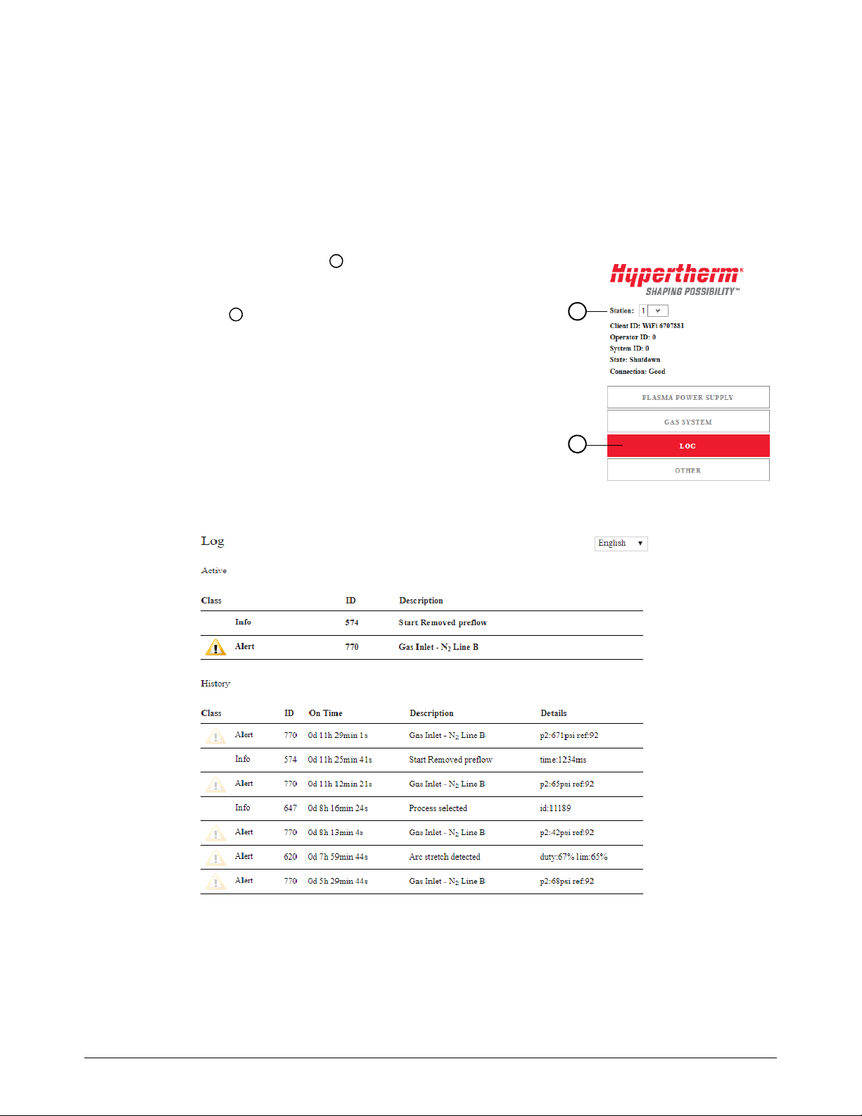
XPR Diagnostics Log
You can view active and recent XPR diagnostic codes, error details, and On Time data from the Log
in the XPR Diagnostics View at the CNC.
To go to the XPR Diagnostics Log:
1. From the Main screen in Phoenix, select Setups > Diagnostics > XPR System.
2. Select the Station number of the XPR that you want to
monitor.
3. Select Log .
The Log (Figure 7) displays 4 classes of XPR diagnostics
codes: failures, errors, alerts, and info messages. To learn the
differences between each class, refer to Table 7 on page 23.
Figure 7 – Log screen in the XPR Diagnostics View
For troubleshooting steps, refer to the instruction manual supplied with
26 809900 Manual Addendum E DGE Connect
your XPR plasma power supply.

Monitor the XPR from the CNC
1
3
5
2
4
6
1Station ID is the station number of the XPR to
monitor.
2 Client ID is the device that is communicating with
the XPR. Client ID displays as “EDGE Connect”
for all CNCs.
3 Operator ID is the type of connection that sent a
process. The Operator ID displays as “No User” if
the network is disconnected.
4System ID is the type of plasma power supply on
the selected station. System ID displays as
“None” if the selected station is not an XPR.
5State is the current status of the XPR on the
selected station. For more information, see the
instruction manual supplied with your XPR plasma
power supply.
6 Connection is the status of the communication
between Phoenix and the web browser displaying
the diagnostics data.
You can monitor up to two XPR plasma power supplies at the CNC by opening the XPR
Diagnostics View in Phoenix. The information in the Diagnostics View is populated from the XPR
over EtherCAT.
To go to the XPR Diagnostics View in Phoenix:
1. Select Setups > Diagnostics > XPR System.
2. Select the Station of the XPR that you want to monitor.
Cut and Mark with an XPR on an EDGE Connect C NC
State and connection
The main screen of the XPR Diagnostics view in Phoenix shows you the state and connection of the
XPR station that you have selected to monitor. See Figure 8.
Figure 8 – View the XPR plasma power supply’s state and connection status
EDGE Connect Manual Addendum 809900 27

Cut and Mark with an XPR on an EDGE Connect C NC
Firmware versions
To find out which firmware versions are installed on an XPR station:
1. From the XPR Diagnostics view in Phoenix, select the Station number for the XPR.
2. Select the Other tab.
To see a list of the firmware versions that this document supports, refer to Before you begin on
page 7.
The following firmware update procedures are available at www.hypertherm.com/docs
To update XPR firmware automatically over EtherCAT, refer to Application Note 810720.
To update XPR Web Interface and PCB firmware with a USB or a wireless connection, refer
:
to Hypertherm Field Service Bulletin 809820.
28 809900 Manual Addendum E DGE Connect

Cut and Mark with an XPR on an EDGE Connect C NC
1
2
1
2
(Not applicable for XPR170)
Plasma power supply I/O, temperatures, and chopper status
The Plasma Power Supply screen shows you details about active I/O, temperature, and chopper
status. To view the XPR plasma power supply I/O, temperatures, and chopper status:
1. From the Main screen in Phoenix, select
Setups > Diagnostics > XPR System.
2. Select the Station number of the XPR that you want to
monitor.
3. Select Plasma Power Supply .
The Plasma Power Supply screen appears (see Figure 9 on
page 29). This screen also shows inputs and outputs. When
highlighted red or gray, that input or output is active.
Figure 9 – Plasma power supply screen in the XPR Diagnostics View
To view active or recent alerts and errors, go to the Log screen. See
EDGE Connect Manual Addendum 809900 29
page 26.

Cut and Mark with an XPR on an EDGE Connect C NC
1
2
1
2
Monitor and test gas flows
You can monitor and test gas flows from the Gas System screen in the XPR Diagnostics View at the
CNC over EtherCAT.
To view the Gas System screen:
1. From the Main screen in Phoenix, select Setups > Diagnostics > XPR System.
2. Select the Station number of the XPR that you want to
monitor.
3. Select Gas System .
Monitor gas flows
To monitor gas flows from the CNC, view the data on the Gas System screen. See Figure 10.
Figure 10 – Gas System screen
30 809900 Manual Addendum EDGE Connect

Cut and Mark with an XPR on an EDGE Connect C NC
Test gas flows and leaks
Do a gas test to make sure that you are ready to cut or to help diagnose problems with cut quality,
system performance, and consumable life.
To do a gas flow or gas leak test from the CNC, the CNC must have
control of the XPR. The device that sets a process first has control of the
XPR.
To do a gas flow test at the CNC:
1. Go to the Gas System screen in the XPR Diagnostics View. For details, see page 30.
2. Choose the test that you want to do (Preflow, Pierceflow, Cutflow, or Gas Leak).
3. On the “Are you sure?” dialog box, select YES.
seconds.
To cancel a gas flow test, select the same gas flow test button again or
choose a different gas test. Gas leak tests cannot be canceled.
To view gas information, alerts, and errors during or after the test, choose Log. See XPR
Diagnostics Log on page 26.
The test begins immediately and continues for 45
EDGE Connect Manual Addendum 809900 31

Cut and Mark with an XPR on an EDGE Connect C NC
View XPR information with the XPR Web Interface
The XPR Web Interface, which is only available on wireless-enabled devices, provides most of the
same data as you can find in the XPR Diagnostics View at the CNC. Before using a
wireless-enabled device to monitor XPR diagnostics, review the XPR Diagnostics View in
Phoenix to see if the data you need is already available at the CNC. See Monitor the XPR from
the CNC on page 27.
• If the XPR diagnostic data that you need is only available in the XPR Web Interface on a
wireless-enabled device, see the
documentation.
• If you connect the CNC to an XPR's wireless network (Access Point mode), the CNC can only
communicate with the XPR’s network and not with your site's network. To resolve this issue, use Network
mode instead or connect an Ethernet cable from the CNC's LAN connection to a port that has access to
your site’s network. For more details about AP versus Network mode, see the instruction manual supplied
with your XPR plasma power supply.
For Ethernet cable specifications, see Specifications and Installation in
Section 1 of the EDGE
(809340).
instruction manual supplied with your XPR plasma power supply for
®
Connect Installation and Setup Manual
Take an XPR on the EtherCAT network out for service
If you need to turn off one XPR temporarily (for example, for maintenance) but continue to use the
cutting system, you must temporarily remove the XPR from the EtherCAT network configuration.
Removing an XPR from the network configuration, known as taking an XPR out for service, lets you
continue to use the cutting system without field bus faults.
To take an XPR out for service:
1. Turn O F F the C N C.
2. Turn OFF main power to the XPR that you want to take out for service.
3. Turn O N t h e C N C.
After Phoenix opens, it begins to start the EtherCAT network. Then the message shown in
Figure 11 on page 32 appears.
Figure 11
The message shows the XPR that you want to take out for service. In this example, it is the XPR
on Station 1.
32 809900 Manual Addendum E DGE Connect

Cut and Mark with an XPR on an EDGE Connect C NC
4. Choose Yes.
Phoenix removes the XPR from the network configuration and starts the EtherCAT network.
If you restart the CNC while the XPR is out for service, you will need to
respond to the Take Plasma Power Supply 1 Out for Service?
message again. Choose Ye s.
If you try to cut with an XPR that is out for service, the following message
shows.
Figure 12
To put the XPR back in service:
1. Turn O F F the C N C.
2. Turn ON main power to the XPR that you want to put back in service.
3. Turn O N t h e C N C.
Phoenix adds the XPR to the network configuration and starts the EtherCAT network.
EDGE Connect Manual Addendum 809900 33

Cut and Mark with an XPR on an EDGE Connect C NC
Appendix A: About ProNest part programs for XPR
See the EDGE Connect Programmer Reference (809550) for more
information about the codes used for part programming.
ProNest part program format for an XPR
When you use ProNest to create a part program for an XPR, ProNest includes a G59 V509 Fxxxxx
command at the beginning of the part program. This command tells the CNC and the XPR which
record in the cut chart database to use for this part program. The record contains all of the process
parameters needed by the CNC and the XPR to execute the part program, including all of the
process parameters for cutting, marking, and/or True Hole (when applicable).
Make sure that the following Program Code settings are enabled on the
Cutting screen in Phoenix (Setups > Cutting): EIA G59 Code Override,
Process Select Override, EIA Kerf Override, and EIA F-Code Override.
For example: G59 V509 F11189
In this example, the V509 command tells the CNC and the XPR to use record 11189 (80 A O2/Air)
in the cut chart database for this part program.
When the CNC reads the M07 (Cut On) command in the part program, the CNC sends record
number 11189 to the XPR. The XPR then loads the associated cutting process parameters from
record number 11189. At the same time, the CNC loads the cutting process parameters from
record number 11189. The process parameters are as follows:
Arc Voltage
Cut Current
Cut Height
An operator cannot override these parameters at the CNC. To override
process parameters, the modifications must be made in the cut chart in
ProNest. See
Cut Speed
Gas type and flow rate
Kerf
Table 8 on page 36 for more information.
Pierce Height
Pierce Time
Transfer He ight
34 809900 Manual Addendum E DGE Connect

Process overrides
A single G59 V509 Fxxxxx command in the part program
automatically populates the XPR Process Selection fields.
An override code on the M07 line in the part
program modifies these values.
To modify an XPR part program, modify the cut chart in ProNest (or other CAM software) and output
the modified part program to use in Phoenix.
Cut and Mark with an XPR on an EDGE Connect C NC
Override codes
If it is necessary to modify the cutting, marking, or True Hole process parameters in a record in the
cut chart database, you make the modifications in ProNest. These modifications are known as
process overrides. When you output the new part program from ProNest, ProNest indicates the
process overrides with the codes in Table 8 on page 36.
EDGE Connect Manual Addendum 809900 35

Cut and Mark with an XPR on an EDGE Connect C NC
Table 8 – Process parameter override codes
Override code Description
AVO Arc Voltage Override
AVD Arc Voltage Delay Override*
CCO Cut Current Override
CHT Cut Height Override
MAF Mix AR Flow Override
MHF Mix H2 Flow Override
MNF Mix N2 Flow Override
PCF Plasma Cut Flow Override
PHT Pierce Height Override**
PTO Pierce Time Override
SCF Shield Cut Flow Override
SPF Shield Pierce Flow Override
THT Transfer Height Override**
* Also called Automatic Voltage Control (AVC) delay.
** See Pierce height and transfer height overrides.
ProNest includes these process override codes on the M07 command line. This tells Phoenix and
the XPR which standard value from the cut chart record to override with the specified value.
For example: M07 AVO116
In this example, assume that the standard arc voltage specified for this process in the cut chart
record is 118. The AVO116 process parameter override in the part program tells Phoenix and the
XPR to use an arc voltage of 116 instead of 118.
Process overrides applied on the M07 line remain
reloads the standard cut chart values.
in effect until the next M07 command which
Pierce height and transfer height overrides
Pierce height and transfer height are defined in the XPR cut chart as absolute values (in inches or
millimeters). For XPR, pierce height and transfer height overrides are independent of cut height.
Example: M07 CHT0.5 THT0.25 = Cut On, use a 0.5 inch cut height, and use a 0.25 inch transfer
height
In this example, CHT and THT override values are used instead of the cut height and transfer height
values from the cut chart record referenced on the G59 line. Because PHT is not included on the
M07 line, the pierce height value from the cut chart record referenced on the G59 line is used.
36 809900 Manual Addendum EDGE Connect

Cut and Mark with an XPR on an EDGE Connect C NC
Marking codes
To tell Phoenix and the XPR to override the cutting process parameters with the marking process
parameters from the cut chart record, ProNest includes the N2 (Nitrogen) or AR (Argon) code on
the M07 (Cut On) command line.
For example: M07 N2 or M07 AR
In addition, ProNest indicates the marking speed as an Fvalue code after the M07 (Cut On). The
marking speed may be the value from the cut chart or an override value, if you specified a marking
speed override in the cut chart in ProNest.
For example:
M07 N2
F250.
If you are marking text, see also Choose Start to resume plasma cutting
with XPR. on page 42.
If your part requires oxyfuel powder marking with legacy M09 codes, see
page 42.
True Hole codes
To tell Phoenix and the XPR to override the standard cutting process parameters with the True Hole
cutting process parameters from the cut chart record, ProNest includes the TH code on the M07
(Cut On) command line.
For example: M07 TH
This indicates that the True Hole cutting process parameters from the cut chart record, as well as
Phoenix True Hole parameters, will be used for any True Hole-compatible circles instead of the
standard cutting process parameters.
In addition to using the True Hole parameters in the cut chart and in
Phoenix, a ProNest part program automatically applies varying speeds
across multiple hole segments to complete the True Hole technique.
Interior contour codes
For parts with interior contours such as slots, arcs, or holes that are not True Hole-compatible,
ProNest includes the O2S code on the M07 (Cut On) command line. The O2S code tells Phoenix
and the XPR to override the standard cutting process parameters with the O2/O2 cutting process
parameters from the cut chart record.
For example: M07 O2S
EDGE Connect Manual Addendum 809900 37

Cut and Mark with an XPR on an EDGE Connect C NC
Sample ProNest part program
The following is a sample ProNest part program for an XPR.
G59 V509 F11420
(130Amp O2/Air)
G41
M07 AVO132 THT0.25
M51
F80.
G03X0. 7071Y0. 7072I0. 3536J0. 3536
G02I1. 5556J1. 5556
M50
M50H-0. 035
G03X-0. 3536I-0. 1768J-0. 1768
M08
G40
M51
M19
M02
Differences between XPR and HPRXD ProNest part programs
If you have a ProNest part program that was created for an HPRXD,
Hypertherm strongly recommends that you create a new part program
specifically for XPR.
There are many differences between the XPR and the HPRXD cut charts. Thus, there are many
differences between a ProNest part program created for an XPR and a ProNest part program
created for an HPRXD. The key differences involve the following:
Process selection
Marking
True Hole
Overrides
Transfer height and pierce height
Each is described briefly below. See the EDGE Connect Programmer Reference (809550) for full
information about the codes used for part programming.
38 809900 Manual Addendum EDGE Connect

Cut and Mark with an XPR on an EDGE Connect C NC
Process selection
With XPR cut charts, process selection uses a single line of code in the part program. For example:
G59 V509 F11189
This command tells the CNC and the XPR which record in the cut chart database to use for this
part program. The record includes the parameters for torch type, material type, cut current, gas, and
material thickness. Thus, this single command specifies all of those parameters at once.
With HPRXD cut charts, process selection uses several lines of V5xx code in the part program to
specify the parameters for torch type, material type, cut current, gas, and material thickness. For
example:
G59 V502 F34
G59 V503 F1.00
G59 V504 F130
G59 V505 F2
G59 V507 F33
Marking
With XPR cut charts, marking process selection uses the N2 or AR code on the M07 (Cut On) line
in the part program. For example:
G59 V509 F11189
...
M07 N2
...
M08
With HPRXD cut charts, marking uses several lines of code in the part program, including
marking-specific codes. For example:
G59 V525 F27
...
M36 T3
...
M09
...
M10
Note that the marking codes used in HPRXD part programs are not used in XPR part programs.
See Table 9 for more information.
EDGE Connect Manual Addendum 809900 39

Cut and Mark with an XPR on an EDGE Connect C NC
Table 9 – Marking code differences between an XPR and an HPRXD
Code With an XPR, used for... With an HPRXD, used for...
M36 T1 (Select Plasma 1 Process) Cutting and marking Cutting
M07 (Cut On) Cutting and marking Cutting
M08 (Cut Off) Cutting and marking Cutting
M36 T3 (Select Marker 1 process) Not used Marking
M09 (Enable Marker 1) Not used Marking
M10 (Disable Marker 1) Not used Marking
When marking with an XPR using an HPRXD part program, Phoenix
automatically interprets the legacy marking codes correctly, without visibly
changing the codes in the part program if you disable the following
Program Code settings on the Cutting screen in Phoenix (Setups >
Cutting): EIA G59 Code Override, Process Select Override, EIA Kerf
Override, and EIA F-Code Override.
True Hole
With XPR cut charts, True Hole process selection uses the TH code on the M07 (Cut On) line in the
part program. For example:
G59 V509 F11189
...
M07 TH
With HPRXD cut charts, True Hole process selection uses several lines of V5xx code in the part
program. For example:
G59 V502 F34
G59 V503 F1.99
G59 V504 F130
G59 V505 F2
G59 V507 F33
In addition, in an HPRXD part program with True Hole, one speed is applied to the hole. With an
XPR part program with True Hole, varying speeds across multiple segments of the hole are applied.
40 809900 Manual Addendum EDGE Connect

Cut and Mark with an XPR on an EDGE Connect C NC
Overrides
With XPR cut charts, process parameter overrides use an override code on the M07 (Cut On) line in
the part program. For example:
G59 V509 F11189
...
M07 AVO116 THT0.25
With HPRXD cut charts, overrides use V6xx codes in the part program. For example:
G59 V502 F34
G59 V503 F1.00
G59 V504 F130
G59 V505 F2
G59 V507 F33
...
G59 V600 F125
M07
ProNest still uses the V600 and V607 height control override codes as
needed in XPR part programs created for bevel cutting. But no other V6xx
override codes are supported with an XPR.
Pierce height and transfer height
With XPR, pierce height and transfer height overrides are independent of cut height. Pierce height
and transfer height are expressed only as absolute values (in millimeters or inches) in the XPR cut
charts and on the Process screen in Phoenix. For part program code examples, see page 36.
With HPRXD, pierce height and transfer height values are expressed as 50% to 400% of cut
height. For example:
G59 V602 F200 = Set the plasma 1 pierce height factor to 200% of cut height
G59 V604 F75 = Set the plasma 1 transfer height factor to 75% of cut height
EDGE Connect Manual Addendum 809900 41

Cut and Mark with an XPR on an EDGE Connect C NC
Appendix B: Oxyfuel powder marking
Although legacy part programs should be reposted with CAM software, there is a manual way to
use a legacy part program to mark M09 codes with oxyfuel powder and cut M07 codes with XPR.
Follow the guidelines and special sequence of steps below.
Guidelines
Control the CNC in Manual mode.
Use the Move to Pierce function to complete all oxyfuel powder marking first.
It is not possible to switch from Plasma mode to Oxy Fuel mode.
Mark with oxyfuel powder and cut with XPR
To use a legacy part program to mark with oxyfuel powder and cut with XPR:
1. With the part program in Oxy Fuel mode, press Start and then immediately press Stop to
pause the program.
2. Choose Move to Pierce and select the first M09 code pierce point for oxyfuel powder marking.
3. Choose Start to begin oxyfuel powder marking.
4. As soon as all M09 marking codes are complete, immediately choose Stop to pause the part
program.
If you wait too long to pause the program, then the plasma cutting
M07 codes are cut with in Oxy Fuel mode instead of in Plasma
mode.
5. On the Main screen, choose Change Cut Mode and then choose Plasma.
6. Choose the Move to Pierce soft key to skip to the first M07 pierce in the part program.
7. Choose Start to resume plasma cutting with XPR.
42 809900 Manual Addendum E DGE Connect

Appendix C: Options for text marking
Are you marking directly on the CNC
or through ProNest?
Need to mark non-English text?
N
e
e
d
a
s
y
n
c
h
r
o
n
o
u
s
s
t
o
p
o
n
m
a
r
k
i
n
g
?
Using ProNest CNC?
ProNest CNC does not support
marking
Use Phoenix text markerPhoenix text marker option in ProNest
OK to smooth cut geometry?
ProNest
Ye s
Ye s
No
Ye s
No
Disable smoothing
Enable smoothing
CNC
No
No
To determine whether to use ProNest scribe text, the Phoenix text marker option in ProNest, or
the Phoenix Marker Font Generator, see the flowchart below.
Use ProNest scribe text
Cut and Mark with an XPR on an E DGE Connect C NC
ProNest scribe text Phoenix text marker in ProNest Use Phoenix text marker
ProNest scribe text included as individual marking motions in output code. ProNest converts all scribe text to the Phoenix text marker during output. Mark text is applied in Phoenix on the CNC.
• Import CAD text or apply in Advanced Edit
• Asynchronous stop supported on marking motions
• Unicode support
• Upper or lowercase
• Current overrides available
• All part geometry (cutting and marking) will be smoothed during part import, if “Smooth entities” is enabled.
• Using this option without smoothing can result in cosmetically poor results.
• No asynchronous stop
•ASCII text only
• ALL CAPS
• No current overrides
• No asynchronous stop
•ASCII text only
• ALL CAPS
• No current overrides
EDGE Connect Manual Addendum 809900 43
 Loading...