


Automation
Hypertherm Automation
5 Technology Drive, Suite 300
W. Lebanon, NH 03784 USA
Phone: 603-298-7970
Fax: 603-298-7977
PHOENIX® SOFTWARE FOR
YPERTHERM SHAPE CUTTING CONTROL
H
OPERATOR’S MANUAL
Version 8.5 for Touch Screen CNCs
January 2009

D
ISCLAIMER The information in this document is subject to change without notice and should not be
construed as a commitment by Hypertherm Automation. Hypertherm Automation
assumes no responsibility for any errors that appear.
T
RADEMARKS Hypertherm Automation is a wholly owned subsidiary of Hypertherm, Inc.
Command, HT 4400, HD3070 HyDefinition Plasma and HD4070 HyDefinition Plasma
are registered trademarks of Hypertherm, Inc.
FASTLaser is a trademark of Hypertherm, Inc.
EDGE, HyperCAD, HyperNet, HyperNest, Phoenix, and ShapeWizard are registered
trademarks of Hypertherm Automation.
Align, APC, CutPro, Gemini, HPR130, HPR260 HyPerformance Plasma, Mariner,
Nester, Remote Help, Sensor, and Voyager are trademarks of Hypertherm Automation.
HASP is a registered trademark of Aladdin Knowledge Systems Ltd.
Indramat is a trademark of Bosch Rexroth.
Pacific Scientific is a trademark of Danaher Motion.
Pentium and Celeron are registered trademarks of Intel Corporation.
Virus Scan is a registered trademark of McAfee Associates, Inc.
Microsoft, the Microsoft logo, and Windows are registered trademarks of Microsoft
Corporation.
NJWIN is a registered trademark of NJStar Software Corporation.
SERCOS Interface is a trademark of SERCOS North America.
Norton AntiVirus and Norton Ghost are trademarks of Symantec Corporation.
Other trademarks are the property of their respective holders.
C
OPYRIGHT 2009 by Hypertherm Automation. All rights Reserved
Printed in USA
ii

Contents
Safety .......................................................................................................................................... 1
Operating the CNC ................................................................................................................... 1-1
Front Panel Layout ............................................................................................................... 1-1
Power Switch ................................................................................................................. 1-1
Touch Screen ................................................................................................................. 1-1
Front Panel (selected models) ............................................................................................. 1-1
Front Panel Keypad (Voyager III model) .............................................................................. 1-2
PC Keyboard Layout and Functions .............................................................................. 1-3
Key and Menu Functions ..................................................................................................... 1-5
Screen Navigation ................................................................................................................ 1-5
Dropdown List ................................................................................................................ 1-6
Radio Buttons ................................................................................................................. 1-6
Check Box ...................................................................................................................... 1-6
Data Input ....................................................................................................................... 1-6
Help Screen ......................................................................................................................... 1-7
Show Bookmarks ........................................................................................................... 1-8
Automated Operations ......................................................................................................... 1-8
Align Wizard ................................................................................................................... 1-8
CutPro Wizard ................................................................................................................ 1-8
The Main Screen ...................................................................................................................... 2-1
Preview Window ................................................................................................................... 2-1
Watch Window ..................................................................................................................... 2-1
Soft Keys .............................................................................................................................. 2-1
Loading a Part .......................................................................................................................... 3-1
Loading a Part from the Shape Library ................................................................................ 3-1
Loading a Part from a Disk ................................................................................................... 3-2
Downloading a Part from a Host .......................................................................................... 3-5
Saving Part Files to Disk ...................................................................................................... 3-7
Uploading Part Files to a Host ........................................................................................... 3-10
Importing DXF Files ........................................................................................................... 3-12
Raw DXF Files ............................................................................................................. 3-13

Invalid Files ........................................................................................................................ 3-15
Resume Last Part .............................................................................................................. 3-16
Rush Job Interrupt ........................................................................................................ 3-16
Automated Power Loss Recovery ................................................................................ 3-17
Arranging Parts ........................................................................................................................ 4-1
Repeating Parts ................................................................................................................... 4-3
Straight Repeat .............................................................................................................. 4-3
Staggered Repeat .......................................................................................................... 4-4
Nested Repeat ............................................................................................................... 4-5
Aligning Parts ....................................................................................................................... 4-6
Align Wizard ................................................................................................................... 4-6
Aligning Parts Manually .................................................................................................. 4-7
Nesting Parts........................................................................................................................ 4-9
Manual Nesting .............................................................................................................. 4-9
Nester Setup ................................................................................................................ 4-11
Using Manual Nester .................................................................................................... 4-12
Adding Parts ................................................................................................................. 4-12
Saving a Nest ............................................................................................................... 4-14
HyperNest – CNC Automatic Nesting ................................................................................ 4-14
Setting Up HyperNest -- CNC ...................................................................................... 4-15
Using Nesting ............................................................................................................... 4-17
Removing a Part from a Nest ....................................................................................... 4-20
Nest Summary ............................................................................................................. 4-21
Main Screen View of Nest ............................................................................................ 4-22
Cutting Parts ............................................................................................................................ 5-1
CutPro Wizard ...................................................................................................................... 5-1
Cutting in Manual Mode ....................................................................................................... 5-1
Multitasking .......................................................................................................................... 5-4
Pausing Cutting .................................................................................................................... 5-6
Manual Operations ............................................................................................................. 5-10
Rip Cutting ......................................................................................................................... 5-13
Manual Options .................................................................................................................. 5-14
Home Axes......................................................................................................................... 5-16

System Setup ........................................................................................................................... 6-1
Cutting Setup ....................................................................................................................... 6-1
Watch Window Setup ........................................................................................................... 6-7
Process Setup .......................................................................................................................... 7-1
Oxy Fuel ............................................................................................................................... 7-2
Controlling Oxy Fuel with Analog Outputs...................................................................... 7-5
Plasma ................................................................................................................................. 7-8
HD3070 Auto Gas Interface ............................................................................................... 7-11
HD3070 Auto Gas I/O .................................................................................................. 7-13
Inputs ........................................................................................................................... 7-13
Outputs ......................................................................................................................... 7-14
HD4070 and HPR Overview .............................................................................................. 7-14
HPR Cut Charts ........................................................................................................... 7-15
Changing HPR Consumables ...................................................................................... 7-18
FineLine Overview ............................................................................................................. 7-18
Station Configuration .................................................................................................... 7-19
FineLine Cut Charts ..................................................................................................... 7-20
Changing FineLine Consumables ................................................................................ 7-22
Marker ................................................................................................................................ 7-23
Marker Interface ........................................................................................................... 7-23
Using Cut Consumables for Marking ........................................................................... 7-25
Laser Overview .................................................................................................................. 7-27
Laser Cut Types Screen .............................................................................................. 7-28
Laser Cut Charts .......................................................................................................... 7-31
Water Jet ............................................................................................................................ 7-37
Sensor THC Setup ................................................................................................................... 8-1
Cut Setups ........................................................................................................................... 8-2
Plasma Setup ....................................................................................................................... 8-3
Marker Setup ........................................................................................................................ 8-6
Process Watch ..................................................................................................................... 8-8
Main Cut Screen .................................................................................................................. 8-9
Automatic THC Mode ..................................................................................................... 8-9
Sensor THC Setups ........................................................................................................... 8-10

Command THC Setup .............................................................................................................. 9-1
Command THC Main Cut Screen ........................................................................................ 9-4
Automatic THC Mode ..................................................................................................... 9-5
Manual THC Mode ......................................................................................................... 9-6
Machine Interface................................................................................................................. 9-7
Diagnostics and Troubleshooting ........................................................................................ 10-1
Remote Help ...................................................................................................................... 10-1
Installing Shared View .................................................................................................. 10-2
Using Remote Help ...................................................................................................... 10-2
CNC Information ................................................................................................................ 10-4
Using the Oscilloscope Function ........................................................................................ 10-6
Saving the Oscilloscope File ........................................................................................ 10-7
Loading an Oscilloscope File ....................................................................................... 10-7
Viewing an Oscilloscope File ....................................................................................... 10-8
Serial Port .......................................................................................................................... 10-9
Plasma System ................................................................................................................ 10-11
Error Messages ................................................................................................................ 10-13
Changing Consumables ................................................................................................... 10-18
Saving the Key Log to Disk .............................................................................................. 10-21
Appendix A: Library Shapes .................................................................................................. A-1
Rectangle ............................................................................................................................ A-2
Circle ................................................................................................................................... A-4
Triangle ............................................................................................................................... A-6
L-Bracket ............................................................................................................................. A-8
Trapezoid .......................................................................................................................... A-10
Slant Rectangle ................................................................................................................. A-12
Gambrel Rectangle ........................................................................................................... A-14
Roofed Rectangle ............................................................................................................. A-16
4-Sided Polygon ................................................................................................................ A-18
5-Sided Polygon ................................................................................................................ A-20
Oval ................................................................................................................................... A-22
Circle with Flat Side .......................................................................................................... A-24
Circle Slice ........................................................................................................................ A-26

Straight Slots ..................................................................................................................... A-28
Angled Slots ...................................................................................................................... A-30
Horizontal Rip.................................................................................................................... A-32
Vertical Rip ........................................................................................................................ A-34
Flange ............................................................................................................................... A-36
Circle with Rectangular Hole ............................................................................................. A-38
Gusset ............................................................................................................................... A-40
8-Sided .............................................................................................................................. A-42
Rectangle with Convex Corners ........................................................................................ A-44
Rectangle with Concave Corners ...................................................................................... A-46
L-Bracket with Elbow Radii ............................................................................................... A-48
Slant L-Bracket with Elbow Radii ...................................................................................... A-50
Trapezoid with Convex Corners ........................................................................................ A-52
Flange Slice ...................................................................................................................... A-54
Elbow ................................................................................................................................ A-56
Flange Repair Ring ........................................................................................................... A-58
Rectangle with Rectangular Hole ...................................................................................... A-60
Rectangle with Circular Hole ............................................................................................. A-62
Rectangle with Circular Hole and Convex Corners ........................................................... A-64
Rectangle with Tab ........................................................................................................... A-66
Rectangle with Convex Tab .............................................................................................. A-68
Rectangle with Notch ........................................................................................................ A-70
Rectangle with Slant Notch ............................................................................................... A-72
Rectangle with Radius Notch ............................................................................................ A-74
Convex Rectangle ............................................................................................................. A-76
Concave Rectangle ........................................................................................................... A-78
Triangle with Concave Side .............................................................................................. A-80
Polygon with Concave Side .............................................................................................. A-82
Slant Rectangle with Radius ............................................................................................. A-84
Slant Rectangle with Circular Hole .................................................................................... A-86
Slant Rectangle with Beveled Corners .............................................................................. A-88
Cross ................................................................................................................................. A-90
Cross with Circular Hole and Concave Inside Corners ..................................................... A-92
4 Sided Convex Rectangle ................................................................................................ A-94
4 Sided Concave Rectangle .............................................................................................. A-96

Pipe Mount ........................................................................................................................ A-98
Bolt Hole Circle ............................................................................................................... A-100
Bolt Hole Flange.............................................................................................................. A-102
Bolt Hole Rectangle ........................................................................................................ A-104
Bolt Hole Rectangle with Convex Corners ...................................................................... A-106
Bolt Hole Rectangle with Center Hole ............................................................................. A-108
Bolt Hole Rectangle with Center Hole and Convex Corners ........................................... A-110
Rounded L-Bracket ......................................................................................................... A-112
Horseshoe ....................................................................................................................... A-114
Convex Roof Trapezoid with Hole ................................................................................... A-116
Convex Roof Polygon with Hole ...................................................................................... A-118
Convex Roof Polygon with Oval Hole and Concave Bottom ........................................... A-120
Pulley Cover .................................................................................................................... A-122
Paddle Blind .................................................................................................................... A-124
Water Pump Gasket ........................................................................................................ A-126
Frame .............................................................................................................................. A-128
Pulley .............................................................................................................................. A-130
Sprocket .......................................................................................................................... A-132
Text ................................................................................................................................. A-134
Test Pattern..................................................................................................................... A-136

Safety
Read This Manual
Read and understand this instructional manual, the cutting machine manuals, and your
employer’s safety practices.
Note: This product is not designed to be field serviceable. Please return to an authorized repair
center for any required service.
Product Listings
MicroEdge and Voyager III
Note: This product has been designed and manufactured in accordance with CE and UL Safety
Standards.
Edge TI
Note: This product has been designed and manufactured in accordance with CE and UL Safety
Standards.
Please contact Hypertherm Automation for further safety listing information.
1
2 Safety
RECOGNIZE SAFETY INFORMATION
The symbols shown in this section are used to
identify potential hazards. When you see a safety
symbol in this manual or on your machine, understand
the potential for personal injury, and follow the related
instructions to avoid the hazard.
FOLLOW SAFETY INSTRUCTIONS
Read carefully all safety messages in this manual and
safety labels on your machine.
• Keep the safety labels on your machine in good
condition. Replace missing or damaged labels
immediately.
• Learn how to operate the machine and how to use
the controls properly. Do not let anyone operate it
without instruction.
• Keep your machine in proper working condition.
Unauthorized modifications to the machine may
affect safety and machine service life.
DANGER WARNING CAUTION
A signal word DANGER or WARNING is used with a
safety symbol. DANGER identifies the most serious
hazards.
• DANGER and WARNING safety labels are located
on your machine near specific hazards.
• WARNING safety messages precede related
instruc tions in this manual that may result in injury
or death if not followed correctly.
• CAUTION safety messages precede related
instructions in this manual that may result in
damage to equipment if not followed correctly.
Fire Prevention
• Be sure the area is safe before doing any cutting.
Keep a fire extinguisher nearby.
• Remove all flammables within 35 feet (10 m) of the
cutting area.
• Quench hot metal or allow it to cool before handling
or before letting it touch combustible materials.
• Never cut containers with potentially flammable
materials inside – they must be emptied and
properly cleaned first.
• Ventilate potentially flammable atmospheres before
cutting.
• When cutting with oxygen as the plasma gas, an
exhaust ventilation system is required.
Explosion Prevention
• Do not use the plasma system if explosive dust or
vapors may be present.
• Do not cut pressurized cylinders, pipes, or any
closed container.
• Do not cut containers that have held combustible
materials.
CUTTING CAN CAUSE FIRE OR EXPLOSION
WARNING
Explosion Hazard
Argon-Hydrogen and Methane
Hydrogen and methane are flammable gases that
present an explosion hazard. Keep flames away from
cylinders and hoses that contain methane or hydrogen
mixtures. Keep flames and sparks away from the torch
when using methane or argon-hydrogen plasma.
WARNING
Hydrogen Detonation with Aluminum Cutting
• When cutting aluminum underwater, or with the
water touching the underside of the aluminum, free
hydrogen gas may collect under the workpiece and
detonate during plasma cutting operations.
• Install an aeration manifold on the floor of the water
table to eliminate the possibility of hydrogen
detonation. Refer to the Appendix section of this
manual for aeration manifold details.

Safety 3
Touching live electrical parts can cause a fatal shock
or severe burn.
• Operating the plasma system completes an
electrical circuit between the torch and the
workpiece. The workpiece and anything touching
the workpiece are part of the electrical circuit.
• Never touch the torch body, workpiece or the water
in a water table when the plasma system is
operating.
Electric Shock Prevention
All Hypertherm plasma systems use high voltage
in the cutting process (200 to 400 VDC are
common). Take the following precautions when
operating this system:
• Wear insulated gloves and boots, and keep your
body and clothing dry.
• Do not stand, sit or lie on – or touch – any wet
surface when using the plasma system.
• Insulate yourself from work and ground using dry
insulating mats or covers big enough to prevent any
physical contact with the work or ground. If you must
work in or near a damp area, use extreme caution.
• Provide a disconnect switch close to the power
supply with properly sized fuses. This switch allows
the operator to turn off the power supply quickly in
an emergency situation.
• When using a water table, be sure that it is correctly
connected to earth ground.
ELECTRIC SHOCK CAN KILL
• Install and ground this equipment according to the
instruction manual and in accordance with national
and local codes.
• Inspect the input power cord frequently for damage
or cracking of the cover. Replace a damaged power
cord immediately. Bare wiring can kill.
• Inspect and replace any worn or damaged torch
leads.
• Do not pick up the workpiece, including the waste
cutoff, while you cut. Leave the workpiece in place
or on the workbench with the work cable attached
during the cutting process.
• Before checking, cleaning or changing torch parts,
disconnect the main power or unplug the power
supply.
• Never bypass or shortcut the safety interlocks.
• Before removing any power supply or system
enclosure cover, disconnect electrical input power.
Wait 5 minutes after disconnecting the main power
to allow capacitors to discharge.
• Never operate the plasma system unless the power
supply covers are in place. Exposed power supply
connections present a severe electrical hazard.
• When making input connections, attach proper
grounding conductor first.
• Each Hypertherm plasma system is designed to be
used only with specific Hypertherm torches. Do not
substitute other torches which could overheat and
present a safety hazard.
Use proper precautions when handling printed
circuit boards.
STATIC ELECTRICITY CAN DAMAGE CIRCUIT BOARDS
• Store PC boards in anti-static containers.
• Wear a grounded wrist strap when handling
PC boards.

4 Safety
The plasma arc by itself is the heat source used for
cutting. Accordingly, although the plasma arc has not
been identified as a source of toxic fumes, the
material being cut can be a source of toxic fumes or
gases that deplete oxygen.
Fumes produced vary depending on the metal that is
cut. Metals that may release toxic fumes include, but
are not limited to, stainless steel, carbon steel, zinc
(galvanized), and copper.
In some cases, the metal may be coated with a
substance that could release toxic fumes. Toxic
coatings include, but are not limited to, lead (in some
paints), cadmium (in some paints and fillers), and
beryllium.
Gases produced by plasma cutting vary based on the
material to be cut and the method of cutting, but may
include ozone, oxides of nitrogen, hexavalent
chromium, hydrogen, and other substances if such
are contained in or released by the material being cut.
Caution should be taken to minimize exposure to
fumes produced by any industrial process. Depending
upon the chemical composition and concentration of
the fumes (as well as other factors, such as
ventilation), there may be a risk of physical illness,
such as birth defects or cancer.
It is the responsibility of the equipment and site owner
to test the air quality in the area where the equipment
is used and to ensure that the air quality in the
workplace meets all local and national standards
and regulations.
TOXIC FUMES CAN CAUSE INJURY OR DEATH
The air quality level in any relevant workplace
depends on site-specific variables such as:
• Table design (wet, dry, underwater).
• Material composition, surface finish, and
composition of coatings.
• Volume of material removed.
• Duration of cutting or gouging.
• Size, air volume, ventilation and filtration of the
work area.
• Personal protective equipment.
• Number of welding and cutting systems in
operation.
• Other site processes that may produce fumes.
If the workplace must conform to national or local
regulations, only monitoring or testing done at the site
can determine whether the site is above or below
allowable levels.
To reduce the risk of exposure to fumes:
• Remove all coatings and solvents from the metal
before cutting.
• Use local exhaust ventilation to remove fumes from
the air.
• Do not inhale fumes. Wear an air-supplied
respirator when cutting any metal coated with,
containing, or suspected to contain toxic elements.
• Assure that those using welding or cutting
equipment, as well as air-supplied respiration
devices, are qualified and trained in the proper use
of such equipment.
• Never cut containers with potentially toxic materials
inside. Empty and properly clean the container first.
• Monitor or test the air quality at the site as needed.
• Consult with a local expert to implement a site plan
to ensure safe air quality.

Safety 5
Instant-On Torches
Plasma arc comes on immediately when the torch
switch is activated.
A PLASMA ARC CAN CAUSE INJURY AND BURNS
The plasma arc will cut quickly through gloves and
skin.
• Keep away from the torch tip.
• Do not hold metal near the cutting path.
• Never point the torch toward yourself or others.
Eye Protection Plasma arc rays produce intense
visible and invisible (ultraviolet and infrared) rays that
can burn eyes and skin.
• Use eye protection in accordance with applicable
national or local codes.
• Wear eye protection (safety glasses or goggles with
side shields, and a welding helmet) with appropriate
lens shading to protect your eyes from the arcʼs
ultraviolet and infrared rays.
Lens Shade
Arc Current AWS (USA) ISO 4850
Up to 100 A No. 8 No. 11
100-200 A No. 10 No. 11-12
200-400 A No. 12 No. 13
Over 400 A No. 14 No. 14
ARC RAYS CAN BURN EYES AND SKIN
Skin Protection Wear protective clothing to protect
against burns caused by ultraviolet light, sparks and
hot metal.
• Gauntlet gloves, safety shoes and hat.
• Flame-retardant clothing to cover all exposed areas.
• Cuffless trousers to prevent entry of sparks and
slag.
• Remove any combustibles, such as a butane lighter
or matches, from your pockets before cutting.
Cutting Area Prepare the cutting area to reduce
reflection and transmission of ultraviolet light:
• Paint walls and other surfaces with dark colors to
reduce reflection.
• Use protective screens or barriers to protect others
from flash and glare.
• Warn others not to watch the arc. Use placards or
signs.
Work Cable Attach the work cable securely to the
workpiece or the work table with good metal-to-metal
contact. Do not connect it to the piece that will fall
away when the cut is complete.
Work Table Connect the work table to an earth
ground, in accordance with appropriate national or
local electrical codes.
GROUNDING SAFETY
Input Power
• Be sure to connect the power cord ground wire to
the ground in the disconnect box.
• If installation of the plasma system involves
connecting the power cord to the power supply, be
sure to connect the power cord ground wire
properly.
• Place the power cord's ground wire on the stud first,
then place any other ground wires on top of the
power cord ground. Fasten the retaining nut tightly.
• Tighten all electrical connections to avoid excessive
heating.

6 Safety
ADDITIONAL SAFETY INFORMATION
1. ANSI Standard Z49.1,
Safety in Welding and Cutting,
American
Welding Society, 550 LeJeune Road
P.O. Box 351020, Miami, FL 33135
2. ANSI Standard Z49.2,
Fire Prevention in the Use of Cutting and
Welding Processes,
American National Standards Institute
1430 Broadway, New York, NY 10018
3. ANSI Standard Z87.1,
Safe Practices for Occupation and
Educational Eye and Face Protection,
American National
Standards Institute, 1430 Broadway, New York, NY 10018
4. AWS F4.1,
Recommended Safe Practices for the Preparation for
Welding and Cutting of Containers and Piping That Have Held
Hazardous Substances,
American Welding Society
550 LeJeune Road, P.O. Box 351040, Miami, FL 33135
5. AWS F5.2,
Recommended Safe Practices for Plasma Arc
Cutting,
American Welding Society
550 LeJeune Road, P.O. Box 351040, Miami, FL 33135
6. CGA Pamphlet P-1,
Safe Handling of Compressed Gases in
Cylinders,
Compressed Gas Association
1235 Jefferson Davis Highway, Arlington, VA 22202
7. CSA Standard W117.2,
Code for Safety in Welding and Cutting,
Canadian Standards Association Standard Sales
178 Rexdale Boulevard, Rexdale, Ontario M9W 1R3, Canada
8. NFPA Standard 51B,
Cutting and Welding Processes,
National
Fire Protection Association
470 Atlantic Avenue, Boston, MA 02210
9. NFPA Standard 70–1978,
National Electrical Code,
National Fire
Protection Association, 470 Atlantic Avenue, Boston, MA 02210
10. OSHA,
Safety and Health Standards,
29FR 1910
U.S. Government Printing Office, Washington, D.C. 20402
• Never lubricate cylinder valves or regulators with oil
or grease.
• Use only correct gas cylinders, regulators, hoses
and fittings designed for the specific application.
• Maintain all compressed gas equipment and
associated parts in good condition.
• Label and color-code all gas hoses to identify the
type of gas in each hose. Consult applicable
national or local codes.
GAS CYLINDERS CAN
EXPLODE IF DAMAGED
COMPRESSED GAS EQUIPMENT SAFETY
Gas cylinders contain gas under high pressure. If
damaged, a cylinder can explode.
• Handle and use compressed gas cylinders in
accordance with applicable national or local codes.
• Never use a cylinder that is not upright and secured
in place.
• Keep the protective cap in place over valve except
when the cylinder is in use or connected for use.
• Never allow electrical contact between the plasma
arc and a cylinder.
• Never expose cylinders to excessive heat, sparks,
slag or open flame.
• Never use a hammer, wrench or other tool to open
a stuck cylinder valve.
Prolonged exposure to noise from cutting or gouging
can damage hearing.
• Use approved ear protection when using plasma
system.
• Warn others nearby about the noise hazard.
NOISE CAN DAMAGE HEARING
Pacemaker and hearing aid operation can be affected
by magnetic fields from high currents.
Pacemaker and hearing aid wearers should consult a
doctor before going near any plasma arc cutting and
gouging operations.
To reduce magnetic field hazards:
• Keep both the work cable and the torch lead to one
side, away from your body.
• Route the torch leads as close as possible to the
work cable.
• Do not wrap or drape the torch lead or work cable
around your body.
• Keep as far away from the power supply as
possible.
PACEMAKER AND HEARING
AID OPERATION
A PLASMA ARC CAN
DAMAGE FROZEN PIPES
Frozen pipes may be damaged or can burst if you
attempt to thaw them with a plasma torch.

Safety 7
WARNING LABEL
This warning label is affixed to some power supplies. It is
important that the operator and maintenance technician
understand the intent of these warning symbols as described.
The numbered text corresponds to the numbered boxes on
the label.
1. Cutting sparks can cause explosion or fire.
1.1 Keep flammables away from cutting.
1.2 Keep a fire extinguisher nearby, and have
a watchperson ready to use it.
1.3 Do not cut on any closed containers.
2. The plasma arc can cause injury and
burns.
2.1 Turn off power before disassembling torch.
2.2 Do not hold the material near cutting path.
2.3 Wear complete body protection.
3. Electric shock from torch or wiring can kill.
Protect yourself from electric shock.
3.1 Wear insulating gloves. Do not wear wet or
damaged gloves.
3.2 Insulate yourself from work and ground.
3.3 Disconnect input plug or power before
working on machine.
4. Breathing cutting fumes can be hazardous
to your health.
4.1 Keep your head out of the fumes.
4.2 Use forced ventilation or local exhaust to
remove the fumes.
4.3 Use ventilating fan to remove the fumes.
5. Arc rays can burn eyes and injure skin.
5.1 Wear hat and safety glasses. Use ear
protection and button shirt collar. Use
welding helmet with correct shade of filter.
Wear complete body protection.
6. Become trained and read the instructions
before working on the machine or cutting.
7. Do not remove or paint over (cover)
warning labels.
www.hypertherm.com/weee
110647 Rev. A

8 Safety

Operating the CNC
Front Panel Layout
The Phoenix software is designed for 15” TFT touch screens with 1024 x 768, or higher,
resolution and is used on all CNC models. Individual human machine interface (HMI)
and front panels may vary.
Power Switch
Hypertherm Automation controls are equipped with a momentary contact power switch.
Press this switch briefly then release to power on and power off the CNC.
Press the power switch for 10 seconds to force a hard system shutdown of Windows
and the CNC. Generally, a hard shutdown is not recommended.
Touch Screen
The touch screen software interface allows direct key input on the screen through the
use of check boxes, radial boxes, drop down selections and data input. Data input
boxes will automatically display a numeric or alphanumeric keypad depending on
datatype.
Front Panel (selected models)
Icon Function
Emergency stop
Start
Stop
Move forward or backward on path
Torch up/down
Manual
Speed Pot (manual feedrate)
1-1

Operator’s Manual
Front Panel Keypad (Voyager III model)
Key Function
Press this key to view the online Help file.
Use the arrow keys to select items in a dialog box.
Use the arrow keys to jog in manual mode. Manual key
functions (indicated in green) are available at the Manual,
Pause and Align screens. This keypad is also used for
navigating through a multi-variable dialog box (indicated in
yellow).
Use the Prev and Next buttons to move through the field boxes.
Use Page Up and Down buttons to scroll.
Press the Start key to start a program.
Press the Stop button to stop a program.
1-2

Operating the CNC
Enter numbers or text with the alpha–numeric keypad.
To enter a number, press the key.
To enter a word, press and hold the matching colored shift key
(up arrow) while pressing the desired letter key. The + (plus)
and – (minus) keys are used to add and delete features at
selection and check boxes.
The alternate (ALT) soft key indicates that more soft keys and
features are available when you press this soft key on screen.
When the alternate soft key is displayed, use the purple
shift to view additional soft keys.
Press the space key to insert a space in a data entry field.
Use the space key to toggle between settings ( for example,
preheat sense input open or closed ).
You can also use the space key to add or delete features at
selection and check boxes.
Deletes the current character in the data entry field and backs
up one position.
Use the * and ? characters as wild cards to search for files.
Press this key (except during cutting) to return to the previous
menu without saving any changes.
Use the \ and : characters for mapping network drives.
Press Enter to accept the preceding entry.
Use the < and > characters for mapping network drives.
PC Keyboard Layout and Functions
A PC keyboard is a feature on selected CNC models but can be added to all models.
1-3

Operator’s Manual
Key Equivalent Function
F1-F8 Soft keys on the display screen
F9 Start
F10 and Pause Stop
F11 Manual mode
F12 Help
Arrow keys Direction for manual motion
Home Previous field
End Next field
[ Purple arrow shift key
] Blue arrow shift key
Alt F4 Exit Phoenix software.
1-4

Operating the CNC
Warning: This key combination will terminate the application.
Alt Tab Alternate between applications.
Warning: The selected application window displays on top of the
desktop and may cover or hide the CNC software window.
Key and Menu Functions
The following is a short form description of all menu functions in the control. This is only
a brief description of each function. Please consult the subsequent manual sections for
more complete information on operational usage of specific keys.
Note: Screens and features will vary depending on interface selection of Beginner,
Intermediate, or Advanced. For convenience, information provided here is in Advanced
Mode showing all options.
Screen Navigation
The eight keys located at the bottom of the screen act as programmable soft keys.
Soft keys to accept (OK) and reject (Cancel) changes.
1-5

Operator’s Manual
The touch screen software interface allows direct key input on the screen through the
use of check boxes, radio boxes, dropdown lists and data input.
Dropdown List
Press the arrow in the dropdown list to view options.
Radio Buttons
Press the round button to select the corresponding option.
Check Box
Press the square box to enable the corresponding option.
Data Input
Data input boxes automatically display a numeric or alphanumeric keypad depending on
data type. Double click on the field to enter data.
AlphaNumericKeypad
1-6

NumericKeypad
Help Screen
Operating the CNC
The CNC has a help screen function. Press the Help soft key to display Help
information for the screen you are looking at. Press the OK soft key to exit the Help
screen and return to the control screen.
1-7

Operator’s Manual
Show Bookmarks
Press the Show Bookmarks soft key on the Help screen to view the list of Help topics.
Click on a topic in the list for additional information.
Automated Operations
The Phoenix software that is loaded on your CNC includes two “wizards” that are
designed to automate your part aligning and cutting operations.
Align Wizard
The Align wizard automates the sequence of operations to enter information for a
skewed plate on the table and to align parts on a skewed or aligned plate.
The Align wizard opens automatically from the Align screen or you can press the Align
Wizard soft key on the Align window. For more information, see Align Wizard in the
Arranging Parts chapter.
CutPro Wizard
The CutPro wizard automates the sequence of choices and selections that you must
make before you begin cutting parts. If you have parts, nests, and cutting processes
stored on your system, you can use the CutPro wizard to simplify cutting operations.
You can launch the Align wizard from the CutPro wizard so you can align plates and
parts during your cut setup.
The CutPro wizard opens automatically from the Main screen or you can press the
CutPro Wizard soft key on the Main screen. For more information on the CutPro wizard,
see CutPro wizard in the Cutting Parts chapter.
1-8

The Main Screen
The Main screen is the first screen you see when the CNC powers up.
Preview Window
This window displays the current part that is stored in memory, including its dimensions.
Watch Window
The watch window is the right part of the screen where monitoring features, such as a
speedometer, job keys, positions indicators, cut mode, and time are displayed. You can
configure this part of the screen, using the 10 different monitoring features in the Setups
window.
Soft Keys
The following table describes the soft keys on the Main screen and how they function.
Soft Key Function
Shape
Manager
This soft key takes you to the Shape Manager screen where you can
load a simple shape, edit a part using the text editor or shape wizard
or teach trace a part.
2-1

Operator’s Manual
Files This soft key takes you to the Files screen where you can load, save,
download or upload part files.
Current Part
Options
Setups This soft key takes you to the setup screens.
View Part/
View Sheet
Zoom +/- These soft keys allow you to change zoom level.
Scroll bars While the scroll bars are displayed and the control is not cutting, the
This soft key takes you to the Part Options screen where the current
part can be scaled, rotated, mirrored and/or repeated.
View Part lets you view the entire current part in the Preview Window.
View Sheet lets you view a part as it would appear on the plate. After
you press the View Sheet soft key, the display window zooms out to
show the part in relationship to the entire plate.
View Sheet is more useful when proper Plate Size values have been
entered in Cutting Setups.
After zooming out, the display can be zoomed in again by pressing
the + key, which causes horizontal and vertical scroll bars to be
displayed. Press the - key to zoom back out.
view of the plate can be shifted horizontally and vertically by pressing
and moving the scroll bar or by holding down a shift key and pressing
the arrow keys on the keypad.
While the control is cutting, the view will automatically be shifted as
the cut path reaches one of the edges of the view. This mode is useful
in normal cutting to closely follow the cut-path while in zoom.
Change Cut
Mode
Change
Consumable
Zero Position This soft key zeros the current positions on the Transverse and Rail
Allows you to select trial, oxy fuel, plasma, water jet and laser cutting
modes, depending on the setup configuration.
This soft key takes you to the Change Consumable screen.
axes as well as the Dual Gantry axis if used.
2-2

Loading a Part
This chapter describes how to load a part from the Shape Library, a disk, or a host, as
well as how to save files and import DXF files.
Loading a Part from the Shape Library
The CNC contains a built-in Shape Library with more than 68 commonly used shapes.
These shapes are parametric, that is, shapes whose size or geometry you can edit. The
shapes in the library are color-coded from simplest (green) to most complex (black).
To select a simple shape:
1. On the Main screen, press Shape Library.
2. Double click a shape.
3. Press OK.
4. If the selection is incorrect, press Cancel and select the shape again.
Keypad operation:
1. Use the arrow keys to navigate to a shape.
2. Press Enter.
3-1
Operator’s Manual
The shape is displayed with the default parameters or the parameters from the last time
this shape was edited. For more information on the individual shapes and how to edit
them, see Appendix A: Library Shapes.
Loading a Part from a Disk
You can load part programs from internal disk drives, a USB memory stick or external
mapped drives (network option) into working memory on the CNC.
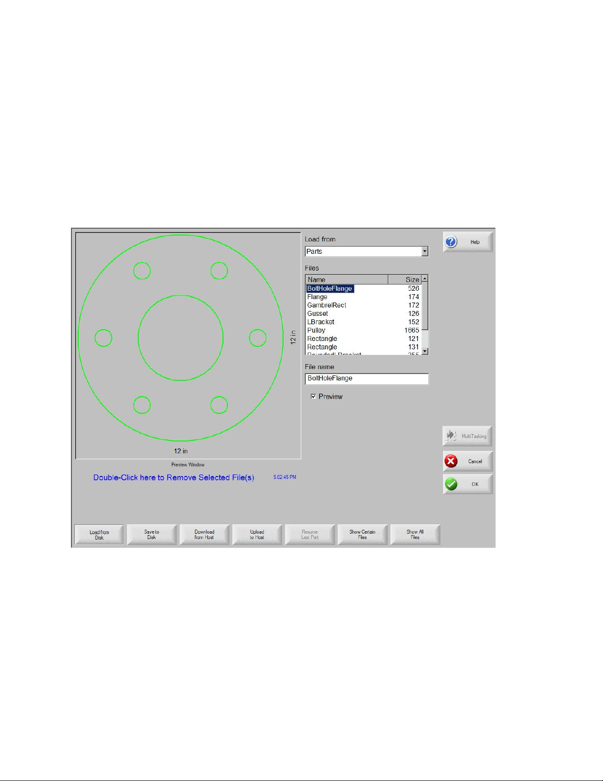
The following screen is used to load a part from a diskette, USB memory stick, or the
hard drive.
Load from Select the source from which you load a part: diskette, USB
memory stick, or a directory on the hard disk. To add or remove a
directory, double-click on the touch screen where indicated.
Keypad operation: To select a different directory, use the ↑ and ↓
keys on the keyboard. To add or remove new directory use the + or
– key.
Files Lists the files that are in the directory you selected in the Load from
3-2

Loading a Part
field. Press the name of the files that you want to load.
Keypad operation: To scroll through different files, use the ↑, ↓,
Page Up and Page Down keys on the keyboard. To remove a file,
use the - key on the keyboard. To select multiple files to load,
highlight the first file selection, then use the ↑ and ↓ keys while
pressing the shift key to highlight the remaining files.
Note: You can only select multiple files if you are loading them
from a diskette or USB memory stick to the hard drive.
File name/
Diskette file name
Preview Check this box to preview the files you selected in the Preview
Load to Select the destination for the part; either load the part for cutting or
Displays the name of the file you selected. To remove a file,
highlight the file name and double-click on the touch screen where
indicated.
Keypad operation: To remove a file using the keyboard, use the –
key.
Window.
save it in a directory on the hard disk. To add or remove a
directory, double-click on the touch screen where indicated.
Keypad operation:
• To select a different directory, use the ↑ and ↓ keys on the
keyboard.
• To add a new directory, use the + key on the keyboard.
• To remove a directory, use the - key on the keyboard.
Hard drive file
name
Show Certain
Files
Note: This selection is only available if you are loading the part
from the diskette or USB memory stick.
Enter the name for the file that you are loading on the hard drive.
Note: This selection is only available if you are loading the part
from the diskette or USB memory stick.
Allows the operator to search the selected folder for specific part
files by using wildcard searches with both the asterisk (*) and
question mark (?).
Keypad operation: To input the asterisk when using a keyboard,
3-3

Operator’s Manual
press the left shift key (purple) and the backspace key. To input the
question mark, press the right shift key (blue) and the backspace
key.
Show All Files Allows the operator to switch from viewing the selected files to
viewing all files with the predetermined file extensions.
After all the parameters are set, press Enter on the keyboard to
load the part.
3-4

Loading a Part
Downloading a Part from a Host
The following screen is where you download a part from a host computer through a RS232C/ RS-422 serial port. After all the parameters below are set, press Enter on the
keyboard to start the download.
Download from Selects the directory on the host computer from which you want to
download a part. To add or remove a directory, double-click on the
touch screen where indicated.
Keypad operation:
• To select a different directory, use the ↑ and ↓ keys on the
keyboard.
• To add or remove new directory use the + or – key.
Files Lists the files in the download from directory that can be
downloaded from the host computer.
Keypad operation:
• To scroll through different files, use the ↑, ↓, PAGE UP and
3-5

Operator’s Manual
PAGE DOWN keys on the keyboard.
• To remove a file, use the - key on the keyboard.
• To select multiple files to download, highlight the first file
selection, then use the ↑ and ↓ keys while pressing the shift key
to highlight the remaining files.
Remote file name The name of the remote file that will be downloaded from the host
computer.
Preview Check this box to preview the file that you selected in the Files list
box. To check or uncheck the box, press the SPACE key on the
keyboard when the Preview box has the focus.
Download to Select where you want to download the part -- to the current part in
memory or to a directory on the local hard disk. If you select one of
the local directories, the Local file name field displays.
Keypad operation:
• To select a different directory, use the ↑ and ↓ keys on the
keyboard.
• To add a new directory, use the + key on the keyboard.
• To remove a directory, use the - key on the keyboard.
Local file name The user-defined file name assigned to the file that is being
downloading to the hard drive.
3-6

Loading a Part
Saving Part Files to Disk
This screen is used to save a part to a diskette, USB memory stick, or the hard drive.
Save to Select whether you save to the diskette, USB memory or to a
directory on the hard disk. To add or remove a directory, doubleclick on the touch screen where indicated.
Keypad operation:
• To select a different directory, use the ↑ and ↓ keys on the
keyboard.
• To add a new directory, use the + key on the keyboard.
• To remove a directory, use the - key on the keyboard.
File name/
Diskette file
Enter the file name that you are giving the file you are loading on
the disk.
If you select the Save Original Text option, the system will save the
part to the disk in its original programming format.
Note: This selection is not available if you are saving the file to the
3-7

Operator’s Manual
diskette or USB memory stick from the hard drive.
Save From Select whether you save from the current part or from a directory
on the hard disk.
To add or remove a directory, double-click on the touch screen
where indicated.
Keypad operation:
• To select a different directory, use the ↑ and ↓ keys on the
keyboard.
• To add a new directory, use the + key on the keyboard.
• To remove a directory, use the - key on the keyboard.
Note: This selection is only available if saving to the Diskette or
USB memory stick from the hard drive.
Files Select one or more part files from the list of all the files that are in
the Load from directory that can be loaded from the disk. To
remove a file, double-click on the touch screen where indicated.
Keypad operation:
• To scroll through different files, use the ↑, ↓, PAGE UP and
PAGE DOWN keys on the keyboard.
• To remove a file, use the - key on the keyboard.
• To select multiple files, highlight the first file selection, then use
the ↑ and ↓ keys while pressing the shift key to highlight the
remaining files.
Note: This selection and Multiple file selection are only available if
you are saving files to the diskette or USB memory stick from the
hard drive.
Hard drive file
name
Preview Check this box to preview the file that is selected in the Files
Enter the name that you are giving to the file if you are loading it on
the hard drive.
Note: This selection is only available if you are saving files to the
diskette or USB memory stick from the hard drive.
listbox.
Keypad operation: To check or uncheck the box, press the Space
3-8

Loading a Part
key on the keyboard when the Preview box has the focus.
Note: This selection is only available if you are saving files to the
diskette or USB memory stick from the hard drive.
After you have made all your selections and entries, press OK to save the part.
3-9

Operator’s Manual
Uploading Part Files to a Host
Use this screen to upload a part to a host computer. After all the parameters are set,
press Enter on the keyboard to start the upload.
Upload to Select the directory on the host computer to which you want to upload
a file. To add or remove a directory, double-click on the touch screen
where indicated.
Keypad operation: To select a different directory, use the ↑ and ↓
keys on the keyboard. To add a new directory, use the + key on the
keyboard. To remove a directory, use the - key on the keyboard.
Remote file
name
Upload from Select whether you upload the current part in memory or from a
Enter the name of the file that you are uploading to the host computer.
directory on the local hard disk. If you select one of the local
directories, the Files, Local file name and Preview fields display. To
3-10

Loading a Part
add or remove a directory, double-click on the touch screen where
indicated.
Keypad operation: To select a different directory, use the ↑ and ↓
keys on the keyboard. To add a new directory, use the + key on the
keyboard. To remove a directory, use the - key on the keyboard.
Note: This selection is only available if you are saving a file to the
diskette or USB memory stick from the hard drive.
Files Lists all the files in the upload from directory that can be uploaded to
the host computer. To remove a file, double-click on the touch screen
where indicated.
Keypad operation: To scroll through different files, use the ↑, ↓,
Page Up and Page Down keys on the keyboard. To remove a file,
use the - key on the keyboard. To select multiple files to upload,
highlight the first file selection, then use the ↑ and ↓ keys while
pressing the shift key to highlight the remaining files.
Local file name The name of the local file that will be uploaded to the host computer.
Preview If you check this box, you can preview the file you selected in the
Preview window.
Keypad operation: To check or uncheck the box, press the SPACE
key on the keyboard when the Preview box has the focus.
3-11

Operator’s Manual
Importing DXF Files
Hypertherm Automation CNCs offer two styles of automated DXF import. The first DXF
feature allows the CAD designer to prepare a DXF file that includes the location of
pierces, pierce order and direction. When this file is loaded into the control, an EIA
format part program will be created for use at the control.
The second type of DXF file is a fully automatic DXF import feature that allows the
control operator to select lead style and length. The CNC Auto DXF software
automatically places the lead-in and lead-out based on the operator selections and
creates an EIA format part program ready for use and the CNC.
To load a DXF file, access the Files Load screen and select the source location and file.
Load from Select dxf from the dropdown list.
File name Select a .dxf file from the scroll box.
Preview Check this box to preview the file that is selected in the File name
scroll box.
Show Certain This soft key allows the operator to show only certain files from the
3-12
Loading a Part
Files selected directory. Both the asterisk and question mark may be
used in defining the files to show.
Keypad operation: The asterisk is generated by holding down the
left shift key and pressing the backspace key. The question mark is
generated by holding down the right shift key and pressing the
backspace key.
Show All Files This soft key allows the operator to undo Show Certain Files.
Note: An optional Network Card for connecting directly to a PC
Network for part file allocation is available.
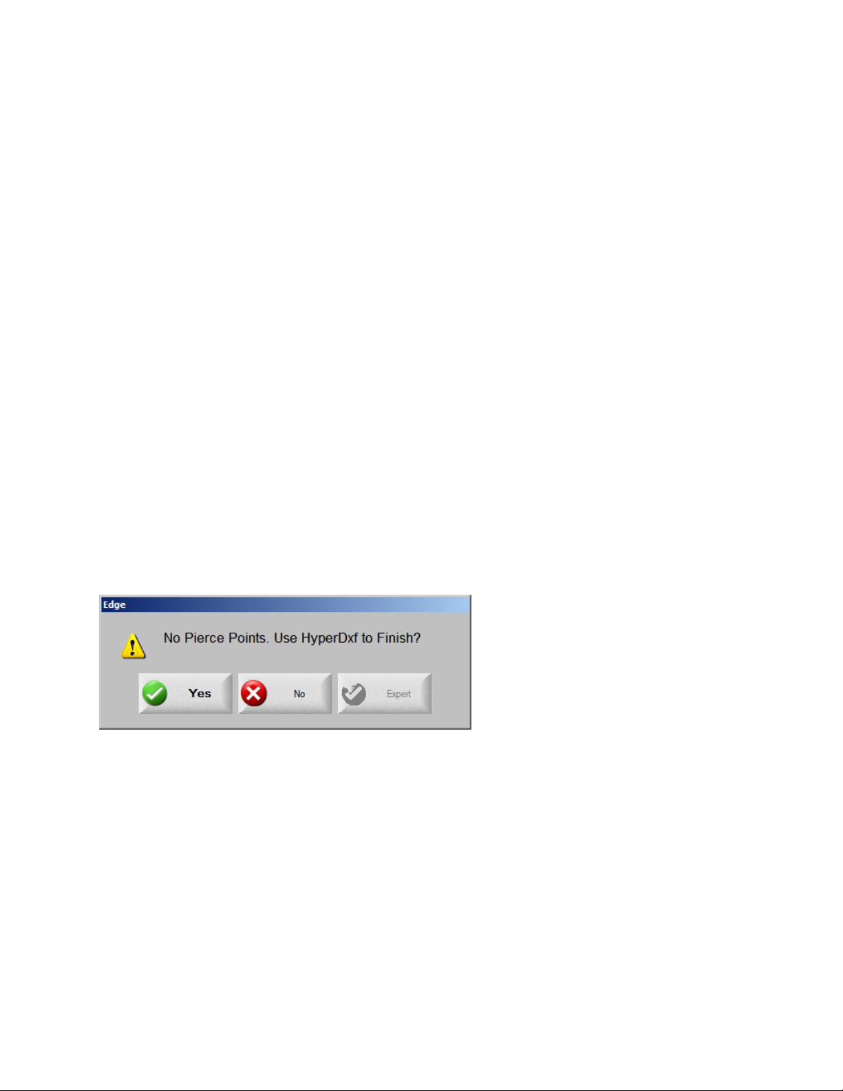
If the file includes the lead-in and direction, the CNC detects this and translates the file.
If the file contains no pierce or lead-in /lead-out information, the HyperDxf utility prompts
the user for this information.
Note: To load DXF files the DXF extension must first be added to the Special Setups
screen.
Raw DXF Files
If the CNC does not detect pierce information in the DXF file, the operator has the
option to use the Hyper DXF translation utility to import the file and add lead-in and
lead-out information.
If you select Yes, a configuration screen displays fields to define the lead-in/ lead-out
format.
3-13

Operator’s Manual
Lead In/Out Select a Straight or Radius lead-in or lead-out.
Length / Radius Select the lead-in or lead-out length or radius.
Angle Select the angle, in degrees, for the lead-in or lead-out.
Auto Position
Lead-in
Auto Corner Align
Lead-in
Inside Lead-out If this box is checked, a lead-out is used on both internal and
Overburn Overburn provides an overlapping cut in the lead-in/ lead-out area
If this box is checked, the software attempts to find a suitable
corner for the lead-in.
If this box is checked, the software attempts to find a suitable
corner for the lead-in.
external cuts. If the box is not checked, lead-outs are added to
external cuts only.
of a hole.
After import, an EIA part program with a .txt extension is created
and placed in the source folder.
3-14

Loading a Part
Invalid Files
While loading the desired part file, the CNC checks the part for proper geometry and
other errors. If an error is detected, a message is displayed:
If the system attempts to load the part, the control highlights the invalid line of code in
the text editor.
For example, in the following sample code, the line of code “XXXXXXXX” is invalid and
has been circled for easy detection. Correct the file using the text editor. After the invalid
code is corrected, the control will attempt to translate the part file and will indicate
additional invalid codes.
3-15

Operator’s Manual
Resume Last Part
Displays when the Rush Job Interrupt or Automated Power Loss Recovery feature is in
use. These features allow you to pause the current part program and retain the part and
current position information. You can load and execute another part program and return
to the original part using the Resume Last Part soft key.
The Resume Last Part soft key is visible when the Rush Job Interrupt or Automated
Power Loss Recovery feature is in use. These features allow the user to pause the
current part program and retain the part and current position information. Then you can
load and execute another part program and return to the original part using the Resume
Last Part soft key.
Note: CNCs with the SERCOS interface will save position information every minute to
the hard drive. Some motion on path may be required for power or position loss
recovery.
Rush Job Interrupt
Allows you to pause the current part program and retain the part and current position
information. At the Pause screen, press the Cancel key. A message window offers you
the opportunity to save the part information to use later.
3-16

Loading a Part
If you select Yes, the Resume Last Part button will be viewable at the Files Screen. The
user can load and execute another part program and then press the Resume Last Part
soft key to return to the original part and resume cutting.
Automated Power Loss Recovery
Uses the Resume Last Part feature similar to the Rush Job Interrupt. However, the
machine must be homed to ensure proper positioning before it can resume cutting the
part.
You can also use this feature if there is an overtravel, or similar fault.
3-17

Operator’s Manual
3-18
Arranging Parts
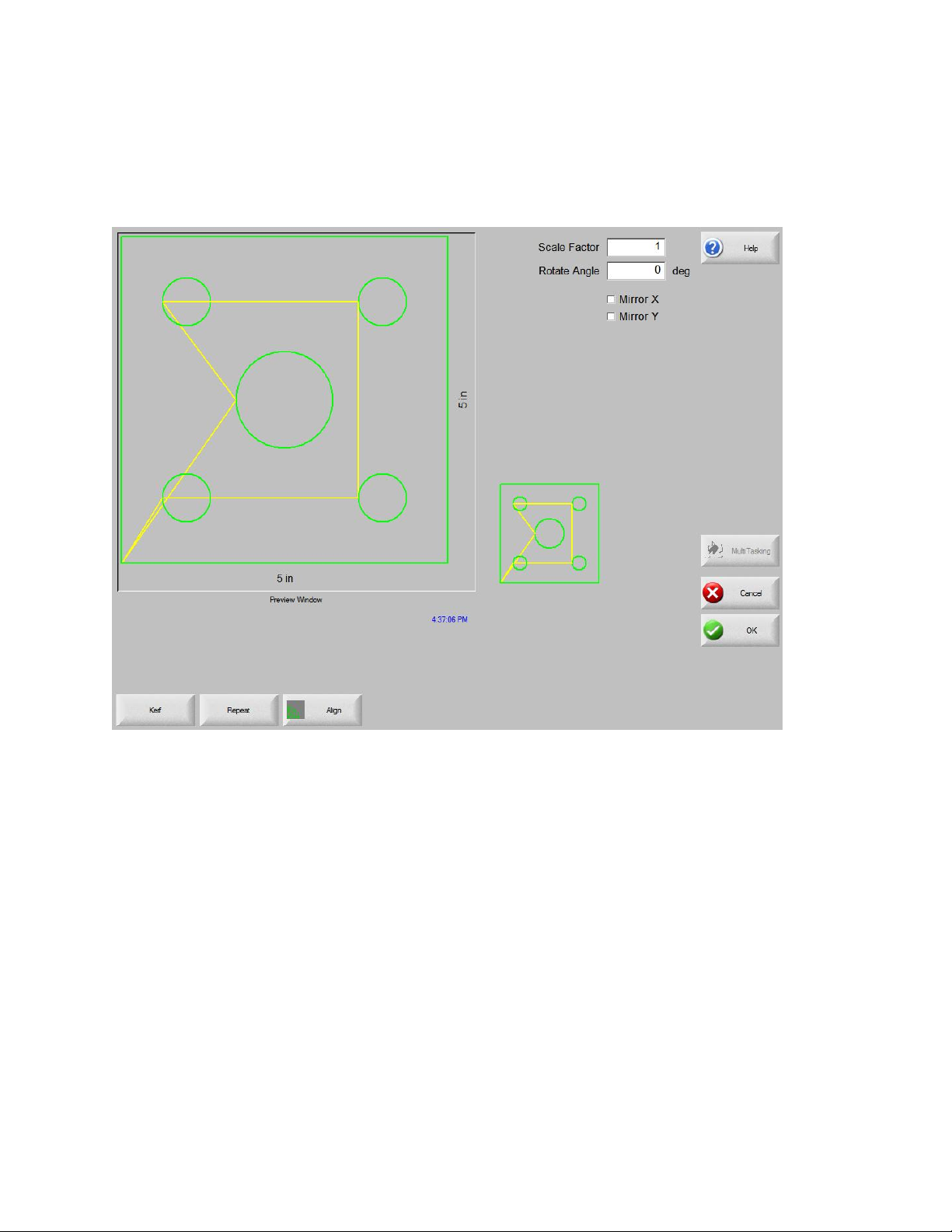
There are a number of options available on the Part Options screen. These options can
be used to customize the current part loaded into working memory. All options will
display the effects of the changes in the Preview Window.
Scale Factor Allows the operator to scale the current part in memory by a
programmed factor. After a new scale factor has been entered, the
part is redrawn and its overall dimensions shown. The scale factor
must be greater than zero.
Rotate Angle Allows the operator to rotate the current part in memory by a
programmed value. After a new rotate angle has been entered, the
new part is displayed in the Preview window. The rotate angle can be
any positive or negative angle.
Mirror X/Mirror Y These checkboxes make the X or Y dimensions negative. The result
is a mirror image of the current part in memory.
For keypad operation, press the Next or Enter key to toggle to the X
or Y field. When the cursor is on the field, press the Space key to
enter a checkmark in the current highlighted field.
Kerf Press the Kerf soft key to show the kerf path in light blue. This helps
you see the Kerf path before cutting. Press the button again to turn
4-1

Operator’s Manual
the Kerf part graphics off.
4-2

Arranging Parts
Repeating Parts
The control has three built-in automatic repeat types: straight, staggered, and nested.
Straight Repeat
Repeat Type Allows the user to select which type of the three repeats to use:
Straight, Staggered or Nested.
Start Corner Allows the user to select which corner of the plate from which to start
the shape repeat.
Number of
Rows
Number of
Columns
X Pattern
Offset/
Y Pattern
Offset
Scrap
Clearance
Program the number of rows to cut.
Program the number of columns.
This control automatically calculates the pattern offset based on the
dimension of the current part in memory.
Allows the user to insert scrap clearance between parts in the grid
pattern. The same value is used for X and Y dimensions.
4-3

Operator’s Manual
Staggered Repeat
X Nest
Distance/
Y Nest
Distance
The control automatically calculates the nest offset based on the
dimension of the current part in memory. This parameter is only
available for the Nested type of repeat.
4-4

Nested Repeat
Arranging Parts
Pattern Offsets This is an automated feature that calculates the minimum spacing
required between repeated parts. The spacing is based on the size of
the part (including lead-in and lead-out), the kerf value and scrap
clearance. This calculated spacing allows the part to be repeated
without overlapping.
You can use this pre-calculated value or select new values manually.
If you enter new pattern offset values, the CNC automatically draws
the new pattern with the new values.
Nest Distance This automated feature calculates the minimum spacing required
between nested parts. The spacing is based on the size of the part
(including lead-in and lead-out), the kerf value and scrap clearance.
This calculated spacing allows the part to be repeated without
overlapping.
You can choose to use this pre-calculated value or select new values
manually. As you enter new offset values, the CNC automatically
draws the new nested pattern with the new values.
Tip: If you change Nest Distance values manually, start with a simple
nest (1 column, 1 row) and perform adjustments based on the display.
The pattern in the Preview window changes as you change values.
When the Nest Distance is what you want, increase the nest size to a
2-column, 2-row nest, then adjust the X and Y pattern offsets again.
When you have the nest spacing you want, increase the nest size to
the maximum that the plate allows.
4-5

Operator’s Manual
Aligning Parts
This screen allows you to:
• Launch the Align wizard.
• Align the current part to one of the four corners of the plate. This is common with
parts that have an internal pierce point such as a flange.
• Accommodate skewed plates when aligning the part. This is commonly used with a
nest of parts that has a small margin of error for placement of the nest on the plate.
Align Wizard
The Align wizard automates the sequence of operations to enter coordinates for a
skewed plate on the table and to align parts to a skewed or aligned plate.
The Align wizard opens automatically from the Align screen or you can press the Align
Wizard soft key on the Align window.
As you work with the Align wizard, it keeps track of your progress and displays it at the
bottom of the wizard window in the progress bar.
You can choose to use the torch or a laser pointer to align the plate. If you choose the
laser pointer, you must have a marker offset value of at least 1 entered for Marker
Offset 10, 11, or 12 on the Setups screen.
4-6

Arranging Parts
Aligning Parts Manually
To align a part manually on the plate:
1. Set parameters that are needed to align your part in the upper right corner of the
screen.
2. Move the torch to the first corner location (Corner to Align with) using the jog keys.
3. Press At Corner.
4. If you are aligning a part, go to step 7.
5. Move the torch to a point along the edge of the plate toward the selected Skew
Reference.
6. Press At Skew Point.
7. Press OK. The machine will move to the start point for the part and return to the
Main screen and be ready for cutting.
Corner to Align
with
Scrap Clearance This is the amount of clearance between the edge of the plate and
Skew Adjustment This determines if the control will adjust for plate skew when
Selects the corner of the plate to align the part in.
the part the control will add in when moving to the start point of the
part.
performing the align function.
4-7

Operator’s Manual
Skew Reference This is the skew reference corner which you will move towards and
mark a point along the edge. This is only available if Skew
Adjustment is On.
At Corner Press this soft key when at the corner of the plate you want to align
the part in.
At Skew Point Press this soft key when at the edge of the plate for skew
adjustment. This is only available if Skew Adjustment is On.
4-8

Arranging Parts
Nesting Parts
Manual Nesting
The main viewing area is the largest area of the screen and is located in the upper left
corner. The edge of the plate is displayed in dark green. The plate size displayed is
based on plate information that has been selected at the main setup screen.
The upper right corner of the main screen displays the part program list for the nest in
order of cut sequence. In the lower right, part position and orientation information for the
selected part program is displayed and can be manipulated for use as new parts are
added.
Add Part Allows you to select a part program from a selected source to add to
the nest.
Remove Part Remove the selected part from the nest parts list.
Cut Earlier Pressing the Cut Earlier soft key will move the selected part program
to an earlier position in the part cut list. The sequence in which the
parts are cut changes, but not the selected part location in the nest.
Cut Later Pressing the Cut Later soft key will move the selected part program to
a later position in the part cut list. The sequence in which the parts are
cut changes, but not the selected part location in the nest.
4-9

Operator’s Manual
View Sheet/
View Part
Arrow Key
(Distance)
Clear Nest Clear Nest will delete all the parts located in the nested parts list from
Setup Pressing the Setup soft key accesses the Nester setup screen for
View Sheet allows the viewing of a part as it would appear on the
plate. After pressing the View Sheet soft key, the display window
zooms out to show the part in relationship to the entire plate.
After zooming out, the display can be zoomed in again by pressing
the + key, which causes horizontal and vertical scroll bars to be
displayed. Pressing the - key will zoom back out.
More information on use of this feature is provided in the Manual
cutting section.
The Arrow Key allows the user to select one of five different preset
move distances when the arrow keys are pressed to locate parts in
the nest. These five distances are definable and are selected in the
Nester setup screen.
temporary memory.
configuring the variable parameters when using Nester.
4-10

Arranging Parts
Nester Setup
The following Setup parameters are used to configure the manual nesting process.
Nesting Select Manual.
Arrow
Increment 1-5
Autoposition Autoposition is an automated feature of the Nester software that
Search The distance for the next available block on the plate that can be used
At this screen, the user can select different move increment
dimensions. These dimensions are used as move distance references
when the control arrow keys are pressed to place parts in position on
the plate.
enables block nesting. This type of nesting compares the overall
block dimensions of the selected part and searches for the next
available block on the plate that is large enough to accommodate the
part being loaded.
Autoposition does not allow parts to be placed on top of other parts or
inside other parts. However, it can be disabled if you want to add
parts to scrap areas.
If Autoposition is not selected, imported parts are stacked in the lower
left corner of the plate and must be manually arranged.
4-11

Operator’s Manual
Increment for the next nested part.
Scrap
Clearance
The amount of space that is added to a block in the nest.
Using Manual Nester
To begin, first select the plate size requirements for the nest at the Main Setup screen.
This information is used to display the plate size and plate orientation at the main view
screen to place parts on the plate. The plate information is retained with the nested part
program when saved.
Press the Nester soft key from the Shape Manager screen then enter the Nester Setup
Screen to configure the nesting software for use. Press OK to return to the Nester Main
Screen to begin placing parts in the nest.
Adding Parts
At the Nester Screen, press the Add Part soft key to add a new part to the nesting part
list. The first screen viewed will allow the user to select a part from the Simple Shape
Library, from a disk or from the host computer via link communications.
After a part has been selected from either location, the user will be prompted to select
the number of pieces desired.
4-12

Arranging Parts
As new parts are added, they are displayed on the selected plate in preparation for final
placement.
At this screen, the part can be oriented, scaled and moved to final position. This is done
by moving to the Nester Part List and highlighting the file name. Then select the desired
field to manually offset, rotate, mirror and scale the part.
4-13

Operator’s Manual
To position the selected part, use the manual direction keys. The view screen will be
outlined by a bold blue border indicating that the arrow keys are active. Pressing the
arrow keys will allow movement of the part to the desired location on the plate. Each
time the arrow keys are pressed, the selected part will move in the direction of the arrow
by the increment set by the Arrow Key distance soft key. Use the arrow distance key,
arrow keys and zooming in the view field, to place the part exactly as you need it.
Add more parts to the nest in the same fashion as described above. To customize your
nest, you may decide to delete parts or add parts to the list and change the order in
which they are cut by use of the soft keys displayed. When finished, press OK to return
to the Main Cut screen and begin cutting the nest. The part nest is currently saved as a
temporary file until another part is loaded.
Saving a Nest
From the Main Cut screen, press the Files soft key then Save to Disk. From here the
part can be saved to a hard disk folder on the CNC, Diskette or USB memory stick. The
nested parts file may be saved as a nest or a part. Saving as a nest using the save as
Nester File feature, will create a larger file which will allow future modification of the nest
through Nester. Nested parts saved as a part file cannot be modified.
HyperNest – CNC Automatic Nesting
The main viewing area of the Nester screen is in the upper left corner and is used to
preview manual nests. During an automatic nest, this area remains blank. The plate
size used during Automatic nesting is based on plate information that has been selected
at the main setup screen.
The upper right corner of the main screen displays the list of part programs and
quantities of parts that have been selected for nesting. In the lower right are fields for
saving the nest with a name and to a folder.
4-14

Arranging Parts
Note: This software feature is protected both by a software enable and a hardware key
(dongle) installed on the CNC.
Setting Up HyperNest -- CNC
Pressing the Setup soft key accesses the following setup parameters and can be used
to configure the automatic nesting process for use.
Note: If this feature is not available (grayed out), the feature has not been enabled on
your CNC. Contact your CNC vendor for details on how to enable the Automatic Nesting
feature.
4-15
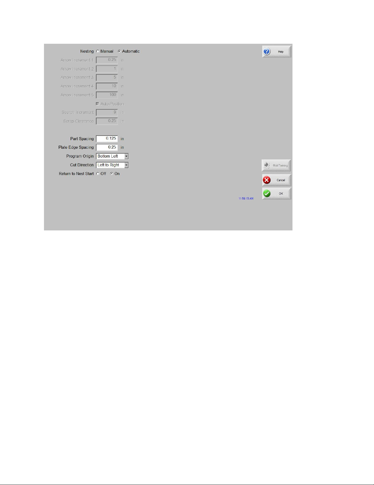
Operator’s Manual
Nesting Switching the Nesting Parameter to Automatic enables the feature.
Arrow
Increment 1-5
Search
Increment
Scrap
Clearance
Cut Direction Cut Direction allows to user to select the direction the parts will be
Nest Direction Select the direction in which nests are placed in the automatic nesting
Return to Nest
Start
Use Remnant If remnants are created and saved for future use, select On to use
Generate and
Cut Offcut
The Part Spacing feature sets the spacing between parts during the
Automatic Nesting process.
This parameter allows the user to set spacing around the edge of the
plate to be used during the Autoposition Nesting process.
The Program Origin (nest start location) may be set to lower left,
upper left, bottom left or bottom right.
placed in during the automatic nesting process. Options are: Left or
Right, Right to Left, Top to Bottom and Bottom to Top.
process.
When enabled, the Return to Nest Start feature will insert a traverse
segment back to the start point at the end of the nest.
one of these remnants for automatic nesting.
Select On to generate offcuts for standard, rectangular nests.
If this feature is enabled, offcuts are created when 30% or more of the
sheet remains after nesting. The offcut is cut after a pause at the end
of the nest on the last nested rectangular sheet.
4-16

Arranging Parts
M65 Auto
Reload
Select On to allow new sheets to be reloaded automatically.
When this feature is selected, there is a pause at the end of each
sheet until the operator presses Start to Resume. Then, a new sheet
automatically loads and runs. Auto reload works with standard,
rectangular nests only.
Using Nesting
1. On the Main Setup screen, select Shape Manager > Nester.
2. On the Nester Screen, press the Add Part soft key to add a new part to the nesting
part list.
3. Select a part from the Shape Library, from a disk or from the host computer via link
communications.
4. In the popup that displays, enter the number of pieces to be included in the nest.
4-17

Operator’s Manual
5. As new parts are added, the part file name and quantity are listed in the Files
window in preparation for final placement during the automatic nesting process.
6. Select a folder for the nest in the Save to dropdown list.
7. Enter the name of the nest in the File name field.
8. Press OK.
A progress window will be displayed during the nesting process.
4-18

Arranging Parts
Note: The nest process progresses quickly and not all shapes may be visible on screen
or other drawing anomalies may be noted during the nesting process.
If more parts are selected than can fit on one plate, multiple plates or sheets (nested
program) files will be generated and saved in the selected folder with the selected file
name, but a numeric suffix will be added. For example, saving the part file as Nest may
generate multiple part files named NEST1.txt, NEST2.txt, NEST3.txt, etc.
4-19

Operator’s Manual
Removing a Part from a Nest
To remove a part from a nest:
1. Highlight the selected part in the Files list.
2. Press the Remove Part soft key.
Note: The software feature on the CNC is protected by a hardware key or dongle. If the
hardware key has been removed from the CNC, the following message will appear
when the Nest Parts soft key has been pressed.
4-20

Arranging Parts
Nest Summary
Upon completion of the nest, the software will provide a summary of the Automatic
Nesting process.
Statistical analysis of the process is provided for the number of sheets, time to execute
nest, total nest utilization and total number of shapes nested.
Note: Sheets that are generated with the exact same part configuration will be listed as
“Sheet No. # (total #)”.
Scroll down to view an analysis of the parts used and to view the individual sheets
produced and a listing of the net utilization for the specific sheet.
4-21

Operator’s Manual
Press OK to accept the nest and have the first sheet become the current part. Press
the Cancel key to reject the nest and return to the main nesting screen to add or remove
parts from the nest.
Main Screen View of Nest
4-22

Arranging Parts
Note: Parts with open loops or other invalid geometries may not be able to be
automatically nested. It may be possible to manually nest parts which have been
rejected by the Automatic Nesting function.
4-23

Operator’s Manual
4-24

Cutting Parts
CutPro Wizard
The CutPro wizard automates the sequence of choices and selections that you must
make before you begin cutting parts. If you have parts, nests, and cutting processes
stored on your system, you can use the CutPro wizard to simplify cutting operations.
The CutPro wizard also helps you to align parts and handle plate skew with the Align
wizard. For more information on the Align wizard, see the Arranging Parts chapter.
The CutPro wizard opens automatically from the Main screen or you can press the
CutPro Wizard soft key on the Main screen. As you work with the CutPro wizard, it
keeps track of your progress and displays it at the bottom of the wizard window in the
progress bar.
Cutting in Manual Mode
After you verify that the cut mode, cut speed and Kerf values are set correctly, press the
Start key on the Main or Manual window to cut a part. The following window is
displayed:
5-1

Operator’s Manual
To cut the part:
1. Verify that the Cut Mode is set to the selected cut type and that the Kerf and Cut
Speed settings are correct.
2. Press the Start key on the front panel.
This starts cutting in the selected Cut Mode.
To preview the path:
1. Press the Change Cut Mode soft key until Trial appears in the Cut Mode window.
2. Press the Start key to have the cutting device follow the cut path without cutting.
Motion is performed at the programmed speed.
3. Press the Stop key on the front panel to stop a cut.
The machine decelerates to a smooth stop along the cut path. If the cutting process
was on when you pressed the Stop key, it is de-activated according to the
programmed cut logic.
During a cut, the Watch window displays information about the part being cut, such as
the current cut speed, current axes positions and path position.
In sheet view, the control automatically scrolls to keep the cut location centered within
the view screen. This feature is useful during normal cutting to zoom in and follow the
cut-path.
5-2

Cutting Parts
View Sheet is useful when proper plate size values have been entered in Cutting setups
and when the machine has been homed. If you attempt to view large parts with a fully
zoomed screen, the part may not be fully drawn on the screen before the next view
location displays and the screen may flash. Zoom out to correct this and view a larger
area.
Increase Speed Increases the current cut speed by 3%.
Decrease Speed Decreases the current cut speed by 3%.
Note: Double click the speed field to enter a new speed value.
Keyboard operation: To change the current cut speed while
cutting a part, press the Enter key once to highlight the current cut
speed, enter the new cut speed, and press Enter again.
Repeats If a Shape Repeat option has been enabled, press the Repeats soft
key to see the number of rows and columns remaining to be cut.
The Repeats soft key operates with the Extend soft key which is
only active during initiation of the cut sequence.
Cut Delay Timers Cut Delay Timers define the timing logic for the cut and are
available for both Oxy-fuel and plasma at the Cut Types setup
screen. In cut mode, the control displays the preset delays as they
are executed in the lower right corner of the screen. For certain
delay times, such as Preheat and Pierce, a countdown timer shows
the preset time and time remaining. An example of the Preheat
Timer is illustrated below:
The Preheat times, Total, Completed and Remaining, are shown to
a tenth of a second.
5-3

Operator’s Manual
When you activate the Cut Sense input, the Preheat delay time cycle ends. The time at
the point of activation becomes the new Preheat time for subsequent cuts.
Three soft keys are also displayed which can be used to modify the Preheat cycle in
progress. The function of these keys is explained below:
Extend Extends the Preheat timer until it is stopped with either the Set-Now
or Release soft key.
Set Now Ends the selected delay timer and saves the new set time. Use the
Set Now soft key with the Extend soft key to modify the preset
Preheat time.
Release Ends the selected delay timer, but does not modify the original delay
time.
Press the Start key twice to bypass the Preheat and Pierce Time Delays and begin the
cut in the Oxy Fuel cut mode.
Multitasking
Multitasking allows you to load and configure a new part program while another part
program is cutting. This feature is only available in advanced operation mode.
To use the multitasking feature:
5-4

Cutting Parts
1. On the Shape Manager screen, press the Multitasking soft key.
The current part program displays in the lower right corner of the Preview Window.
2. Select another part program from the Shape Library or a storage device.
The new program displays in the Preview Window.
3. Press the multitasking soft key to switch between programs.
5-5

Operator’s Manual
Pausing Cutting
If the cut process fails, the CNC has recovery capabilities that are described in the
following table:
Cut Loss
Recovery
Return to Start This feature allows the operator to return to the initial starting point
Backup and
Forward on Path
The Cut Loss Recovery features of the CNC are available from the
Pause screen which displays when the operator presses Stop or if
cut sense is lost.
Press the Cancel key on the Pause screen to cancel the current
part.
of the part program.
Note: If you use the Return to Start function after a cut loss, all
information about the current position of the cutting device on the
path is lost.
Use these two soft keys to move backward and forward along the
cut path at the selected move speed to locate the pierce restart
point. Press the Start key to resume the cut at the programmed cut
speed. In addition to all segments of a standard part, the Backup
and Forward on Path functions allow full movement through all
sections of Shape Repeat part, as well.
5-6

Cutting Parts
Like the Manual Mode functions, Backup and Forward on Path use
the currently selected move speed. The different speeds allow
moving rapidly along the path, or precisely positioning the cutting
device.
When a cut loss occurs, the initial backup and forward speed is the
one that was used last. To toggle between the move speeds, press
the Change Move Speed soft key in the Pause window. The
corresponding speed is displayed in the Move Speed window.
Move to
Pierce/Mark
Change Cut Mode Alternates the restart mode between Cut and Trial. This allows the
Change Move
Speed
On-Path Restart To restart the cut at the pierce point that you selected using On-
Press the Move to Pierce/Mark soft key to move directly to any
pierce point.
Enter the information for the pierce point and press Enter. The
cutting device moves directly to the selected pierce point.
operator to move through the part partially as a trial cut and
partially as an actual cut.
Cycles through the four move speeds that are available. The four
move speeds are the Maximum Machine Speed, High Jog Speed,
Medium Jog Speed and Low Jog Speed from the Speeds setups.
Path Backup, press the START key. The cut speed and the cut
mode are the same as they were before the motion was paused
unless the values have been edited in the Watch window.
While the Pause Window is displays, the manual arrow keys are
fully functional so you can move the cutting device. This allows you
to move the machine in any direction (not necessarily along the
path) to inspect the partially cut piece. Once the cutting device is
moved off the cut path, the Off-path Pause Window displays.
Return to Path Press the Return to Path soft key in the Off-path Pause window to
return the cutting device to the point on the cut path from which it
was jogged away. This feature is useful for inspecting or replacing
components after cut loss and then returning to the cut loss point.
When the cutting device is back on the cut path, the On-path Pause
Window is restored and cutting can resume.
Move Part Moves the entire part on the plate. The point along the cut path to
which the cutting device moves becomes the current position of the
cutting device. The On-path Pause window displays again because
5-7

Operator’s Manual
the cutting device is on path.
Off-Path Restart Press the Start key from the Off-path Pause window, to construct a
lead-in from the off-path point back to the original part.
In a cut loss situation, the operator can use the Backup on Path key
in the On-path Pause window menu to position the cutting device
on the cut path where the cut was lost. The operator can then use
the manual arrow keys to jog the cutting device off path to a
suitable pierce point.
Press Start at this point to cut a new lead-in from the off-path pierce
point to the point along the path from which the cutting device was
jogged away. When the cutting device is back on path, it continues
along the path to cut the remainder of the part.
Rush Job
Interrupt
Allows the user to pause the current part program and retain the
part and current position information. On the Pause screen, press
the Cancel key. A prompt displays on the screen to allow you to
save the part information.
If you select Yes, the Resume Last Part button displays on the
Files Screen. You can load and execute another part program and
then return to the original part using the Resume Last Part soft key.
The part program and position resumes.
5-8

Cutting Parts
5-9

Operator’s Manual
Manual Operations
The manual key is indicated by the hand icon.
Press the manual key on the screen to view the following screen. The directional jog
keys are active when they are green.
Whenever the manual keys are active, the cursor icon in the graphics display window is
the shape of a hand.
From the Manual window, the machine can be moved in one of eight directions using
the arrow keys. The cutting device moves while you hold an arrow key down. When the
key is released, the cutting device comes to a smooth stop.
If the latched manual key feature is enabled in the control setups, press the manual key
a second time to allow motion to continue without holding down the arrow key.
This feature is available for the manual direction keys in the Manual, Align and Pause
screens. When this feature is activated, the dialog “Latched Manual Keys On” will be
displayed in red at the bottom right corner of the part window.
Motion can be paused by use of the Stop, Cancel or an arrow key. The latched manual
key feature can be turned off by pressing the manual key again.
5-10

Cutting Parts
Return to Start Whenever the Manual window is opened, the transverse and rail
positions at that point are saved.
After rip cutting or other manual operations, it may be necessary to
return to this "start" position.
Press the Return to Start soft key to generate motion in the
transverse and rail axes from the machine’s current position to the
position that was saved when the Manual window opened.
Move Distance When Move Only is displayed in the Manual Mode window, the
second soft key from the left changes to Move Distance.
The Move Distance soft key allows you to perform moves over
exact distances. After you press Move Distance, the CNC prompts
you for traverse and rail distance values for the machine’s motion.
Enter the appropriate values and press ENTER.
The cutting device moves the distance you entered in a straight line
without executing any cut logic.
As with any automatic motion, you may press STOP on the front
panel at any time to bring the machine smoothly to a stop before
the programmed motion is complete.
Cut Distance When Rip Cut mode is selected in the Manual Mode window, the
second soft key from the left changes to Cut Distance.
This soft key allows you to make rip cuts of an exact length. After
you press Cut Distance, the control prompts you for traverse and
rail distance values for machine motion. Enter the appropriate
values and press ENTER.
After the cutting device executes the cut logic sequence, it moves
the distance you entered in a straight line.
If you enter incorrect values, press the CANCEL key at any time.
After motion has begun, press STOP on the front panel to bring the
5-11

Operator’s Manual
machine smoothly to a stop before the programmed motion is
complete.
Rip Cut mode is useful for making a cut along a specified linear
path. Motion stops and cutting action ceases when the new position
is reached or when the STOP key is pressed.
If you do not know the exact distance, enter a distance longer than
needed in the right direction, and then press STOP to end the cut.
Manual Options Press the Manual Options soft key to access the Manual Options
screen.
Home Axes Press the Home Axes soft key to access the Homes Axes screen.
View Sheet/View
Part
View Sheet allows you to view a part as it would appear on the
plate. After you press the View Sheet soft key, the display window
zooms out to show the part in relationship to the entire plate.
After the display zooms out, you can zoom in again by pressing the
+ key, which adds horizontal and vertical scroll bars. Press the -
key to zoom out again.
While the scroll bars are displayed, you can hold down the scroll
bar and move it to adjust the view of the machine horizontally and
vertically. This mode is useful in normal cutting to closely follow the
cut path while in zoom.
While cutting in sheet view, the control automatically scrolls to keep
the cut location centered within the view screen. This feature is
useful in normal cutting to follow the cut-path while zoomed in.
View Sheet is more useful when proper plate size values have
been entered in cutting setups and when the machine has already
been homed. If you are viewing large parts being cut with the
display fully zoomed, the system may not be able to draw the part
on screen before it has to move to the next view location. In this
case, the view screen may flash but you can correct this by
zooming out to a larger view area.
Change Manual
Mode
Change Move
Speed
Zero Positions Press this soft key to return all axes positions to 0 (zero).
This soft key alternates the control Manual Mode between Move
Only and Rip Cut.
If you press this soft key the second soft key from the left to
changes function from Move Distance to Cut Distance. Rip Cutting
is described in more detail below.
This soft key toggles through the four Move Speeds: maximum
machine speed, high jog speed, medium jog speed and low jog
speed from the Speeds setups.
5-12

Cutting Parts
Rip Cutting
When the Manual Mode window displays Rip Cut, you can use the arrow keys to begin
a cut sequence and machine motion in the chosen direction.
To initiate a rip cut:
1. Verify that the correct cut-mode has been selected.
2. Verify that the proper cut speed is displayed in the Cut Speed window (editable in
Rip Cut mode).
3. Press the arrow key corresponding to the desired start direction for the cut.
The cutting sequence proceeds even after the key is released; however, machine
motion is generated only as long as an arrow key is held down, unless the
latched manual key feature has been enabled.
4. Use the arrow keys to change direction.
5. Press Stop, Cancel, or Manual to stop the operation of the cutting device.
5-13

Operator’s Manual
Manual Options
Raise Torch Raises the cutting torch while the soft key is pressed or until the
Torch Up sense input is activated.
Lower Torch Lowers the cutting torch while the soft key is pressed or until the
torch down sense input is activated. If the torch down output has
been enabled to stay on during the cut in plasma setups, press the
Lower Torch soft key to keep the torch in the down position until the
Lower Torch soft key is depressed a second time.
Manual Offset Manual Offset is useful for cutting tables that have a laser
alignment tool attached and allows you to use your laser alignment
tool for aligning a part to a plate.
The offset will stay in place until it is turned off from this screen or
a part is cut in either oxy-fuel or plasma cut mode.
You can select the following offsets:
• User Defined – Uses the selected X / Y Offset distance.
• Laser pointer to Plasma 1 – Offset 10
• Laser pointer to Plasma 2 – Offset 11
• Laser pointer to Oxy Fuel – Offset 12
5-14

Cutting Parts
Send Tilt Rotator
Home
Move Rotate Axis
Move Tilt Axis
Adjust Dual
Gantry Skew
Space Torches
Allows you to realign the Dual Gantry Axis manually using the
directional manual jog (arrow ↑ and ↓) keys.
5-15

Operator’s Manual
Home Axes
From the Home screen, each axis or all axes can be "homed". In addition, the
transverse and rail axes can be sent to one of up to 12 programmed alternate home
positions.
The home feature sets a known, absolute physical position location on the cutting table
that is used for referencing future manual “Go to Home” and other motion commands.
This is generally performed through activation of a home switch positioned on the
appropriate axis giving it a known physical location.
When the homing command is entered at the CNC, the CNC moves the axis toward the
home switches at the fast home speed until the switches have been activated. After the
switches have been activated, motion stops and the axis moves in the opposite
direction off switch at the slow home speed.
When switch is deactivated, the position is recorded at the CNC and provides an
absolute reference point for future motion commands.
Transverse Press the Transverse soft key to initiate the automated homing
procedure. This procedure generally produces machine motion in
the transverse axis, depending on the homing parameters set in the
5-16

Cutting Parts
Setups.
Rail Press the Rail soft key to initiate the automated homing procedure.
This procedure generally produces machine motion in the Rail axis,
depending on the homing parameters set in the Setups.
CBH Press the CBH soft key to initiate the automated homing procedure.
This procedure generally produces machine motion in the CBH
axis, depending on the homing parameters set in the Setups.
THC Press the THC soft key to initiate the automated homing procedure
for the Sensor THC. This procedure generally produces machine
motion in the THC axis, depending on the homing parameters set
in the Setups.
Tilt Press the Tilt soft key to initiate the automated homing procedure
for the Tilt Axis.
Rotate Press the Rotate soft key to initiate the automated homing
procedure for the Rotate Axis.
Note: If tilt and rotate axes are enabled, the following window will
appear and allow access to the Tilt/ Rotate or other axes.
Select Yes to access Homing for the Tilt and Rotate Axes.
Select No to access the Homing functions for the other axes.
All Press the All soft key to initiate the automated homing procedure.
This procedure generally produces machine motion in one or more
axes, depending on the homing parameters set in the Setups.
Go To Home
Position
Press one of the four Go To Home Position soft keys to move the
transverse and rail axes to the predefined position set in the
corresponding edit window. The Go To Positions are absolute and
require that an automated home procedure already be executed.
5-17

Operator’s Manual
5-18

System Setup
On the Setup screen, you make the selections that determine how you are going to cut.
Cutting Setup
If you press the Cutting soft key, you can adjust the parameters for the cut mode you
want to use. The available modes are:
• Trial (no cutting) motion
• Oxy-Fuel
• Plasma
• Laser
• Water jet
Cut Mode Specifies the current cut mode. Trial mode allows the operator to dry-
run the current part program without cutting.
Kerf Specifies the amount of kerf that will be applied to the current part
program. Care should be taken when selecting a kerf value as this
parameter can cause invalid geometries to be generated. For
6-1

Operator’s Manual
example, adding a kerf of 0.5” to an arc with a radius of 0.25”. After
entering a kerf value, the kerf compensated cut path can be viewed
by pressing the Kerf soft key under the Part Options menu.
Kerf Variable /
Kerf Value
Trial/Cut Speed Specifies the speed for the current cut mode. These speeds are
Creates a kerf variable table that assigns a variable to a Kerf value.
Up to 200 variables can be entered to create a reference table.
This kerf variable can be used within a part program to define the kerf
value and as torch parts wear, the kerf value changes. If the kerf
variable value is updated as the consumable wears and changes, the
new value will be called by the kerf variable command with all
programs loaded that use the variable.
The EIA-274D part code for left kerf variable is the G43 code. In the
following example, G43 D1 X0.06:
• G43 is the kerf variable setting
• D1 is the kerf variable. Any number from 1 – 200 can be used.
• X0.06 is the selected kerf value.
saved independently for trialing and cutting. Both speeds are limited
to the maximum machine speed. Cut and trial speeds can be
executed at the embedded F-code speed within a part program.
Marker 1 /
Marker 2
Speed
Plate Size Specifies the dimensions of the current plate. This dimension is used
Vent Controls
1 - 50
Marker Offsets
1 - 12
Specifies the speed for the selected marker. These speeds are saved
independently for each marker and are executed through the marker
tool selection within a part program.
Marker 1 is activated by EIA RS-274D M09 and M10, or an ESSI 9
and 10.
Marker 2 is activated by EIA RS-274D M013 and M14, or an ESSI 13
and 14.
when loading a part to determine if it will fit on the plate. It is also used
for viewing the part in screen view.
Enter rail values for up to fifty programmable zones for fume
extraction damper control.
Based on the rail position, the vent controls digital outputs to activate
dampers at the selected zone for increased performance.
Enter values for up to twelve programmable marker offsets. The
machine is offset by this amount at maximum speed when the
6-2

System Setup
appropriate marker code is detected.
If values other than 1 are entered for marker offsets 10, 11 or 12, the
Align wizard and CutPro Wizard will automatically allow the you to
select the use of the laser pointer or the torch for alignment
Dwell Time Specifies the amount of dwell (delay) that is inserted into the current
part program when an appropriate RS-274D program block is
reached. This time can be overridden in the part program. For
example, in EIA programming a G04 X3 causes a three second dwell
to be inserted at the current program block. A G04 with no X-code
inserts a dwell with the current Dwell Time parameter.
Arc Radial
Error
Dwell Override When this parameter is enabled, embedded dwell G04 X value codes
Optional
Program Stop
EIA I & J
Codes
EIA F-Code
Override
Specifies the arc error tolerance to be used when checking the
current segment for dimensional accuracy. All ESSI or EIA programs
are comprised of lines, arcs, and circles. Arc Radial Error is used to
make sure that the starting and ending radial vectors are within
tolerance to describe a valid geometry.
in an RS-274D program override the operator-entered dwell time.
Allows overriding of the optional program stop code M01 in the
current part program. If enabled, an M01 code operates identically to
M00. If disabled, the M01 code is ignored.
Selects absolute or incremental RS-274D programming mode. In
incremental mode, all offsets for X, Y, I and J are relative to the
current block. In absolute mode, all offsets for X, Y, I and J are
relative to an absolute reference point unless they are changed by
using a G92 (set axis presets) program code.
When this parameter is enabled, embedded F-codes in an RS-274D
program override any operator-entered cut speed.
Speed +/Affects FCodes
EIA Decimal
Shift
When this parameter is enabled, the control applies the speed
increase/decrease percentage to all embedded F-codes that are
encountered in the part program.
Some programming styles are structured so that the decimal point in
the EIA positioning affecting part sizing is assumed. The EIA decimal
shift parameter allows the operator to select the location of the
decimal point when translating parts by selecting normal or single for
the correct translation. The selection should be set to Normal unless
your part programs have only a single digit to the right of the decimal
point.
6-3

Operator’s Manual
Process Select
Override
Station Select
Override
Auto Torch
Spacing
Override
G97 Loop
Count Prompt
ESAB Multi
Torch Support
Force G40 Kerf
Disable
When enabled, this feature allows the part program to override the
process select input.
When enabled, this feature allows the part program to override the
currently selected station select input.
When enabled, this feature allows the part program to override the
manually selected torch spacing inputs.
When enabled, this feature will post a message on the screen to enter
the number of loops or repeats to be selected when an EIA G97 code
without a “T” value is encountered in the part program.
When enabled, this feature allows ESAB style ESSI part programs to
map codes to specific station selects.
ESSI Code EIA Code Description
7 M37 T1 Select station 1
8 M38 T1 Deselect station 1
13 M37 T2 Select station 2
14 M37 T2 Deselect station 2
15 M37 T3 Select station 3
16 M38 T3 Deselect station 3
In a part program, kerf is enabled and disabled using EIA G41/ G42
and G40 codes. Standard operation is to disable kerf at the cut off
even if the G40 kerf disable is not in a program. With this parameter,
you can turn off the “forced” G40 kerf disable if no G40 is used in the
program by disabling the parameter.
G40 Used in
Simple Shapes
Auto Start after
APA
EIA Code 2
Decimal Shift
M17, M18 This allows the EIA-274D M17 and M18 codes to be used for cut on
This parameter is used with the Force Kerf Disable parameter to allow
the G40 code that is normally inserted in to a simple shape from the
shape library to be omitted by disabling the parameter.
This parameter is used with the Automatic Plate Alignment feature to
allow cutting to begin automatically after completion of the automatic
plate alignment.
Some programming styles are structured so that the decimal point in
the EIA positioning affecting part sizing is assumed. The EIA Code 2
Decimal Shift parameter allows the operator to select the location of
the decimal point when translating parts by selecting normal or single
for correct translation. The selection should be set to Normal unless
your part programs require two decimal shift to the right of the decimal
point.
6-4

System Setup
Used as Cut
Codes
M76 Rotary
Shortest Path
EIA Kerf
Override
EIA G59 Code
Override
Stop on Single
Arc Lost
and off commands when enabled.
When enabled, this disables tilt and rotate software overtravels for
dual tilt-style bevellers and allows the EIA-274D M76 Rotate go to
Home command to select shortest path. When disabled it allows
motion by longest path when homing. This is advantageous for some
bevel head designs.
If this setting is disabled, all kerf value codes and Load Kerf Table
variable are ignored. This parameter is enabled by default and
cannot be changed while the part program is paused. This is useful
when a process is used at a cutting machine that is different from the
one that was used to create the part program.
If this setting is disabled, all G59 codes are ignored. This parameter
is enabled by default and cannot be changed while the part program
is paused. This is useful when a process is used at a cutting machine
that is different from the one where the program was created.
If this setting is enabled, any cut sense input that is lost for longer
than the arc off time during the cut pauses the part program or nest
with a Cut Sense Lost message.
Show Traverse
Segments
Retain Skew
Adjustment
THC Voltage
Offset
Reenable All
Power Supplies
Allows traverse segment lines (displayed in yellow) to be turned OFF
or ON during all part preview displays.
Retains the last calculated plate skew for all subsequent parts that are
loaded. If disabled, any new part that is loaded will remove any
previously calculated plate skew.
The THC Voltage Offset parameter is used to offset individual Sensor
THC arc voltages from the master set arc voltage. This allows the
individual THCs to be adjusted to compensate for consumable wear
and obtain optimum cut quality.
Note: The THC Voltage Offset parameter can be adjusted
automatically using the Volts per Minute parameter on the Change
Consumable screen.
Press this soft key to re-enable any disabled HD4070 or HPR power
supply with auto gas. This key is enabled only if a power supply has
been disabled.
6-5
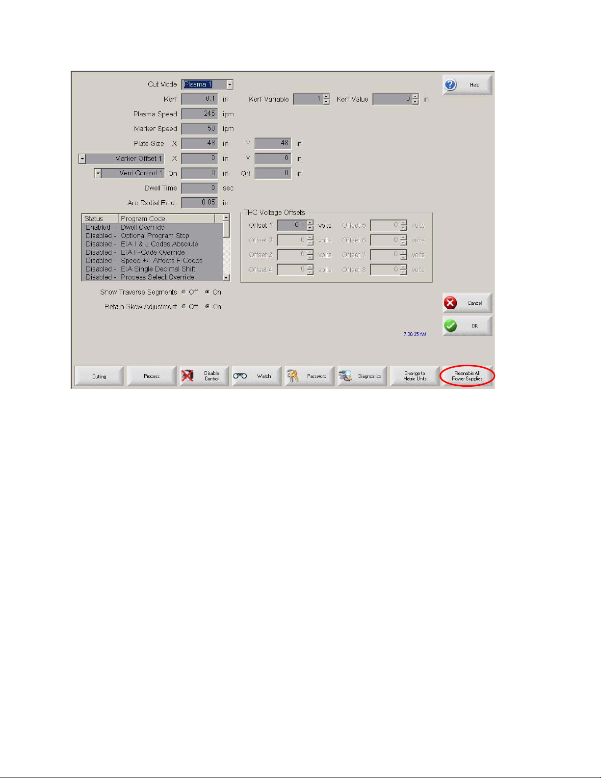
Operator’s Manual
6-6

System Setup
Watch Window Setup
The CNC comes with a unique function for watching critical process-related parameters
during cutting. The Watch window allows the operator to customize a certain portion of
the screen to display functions that are critical for your particular cutting operation.
Whether it is Current Speed, Position, I/O status, or torch consumable life, you can
display the information that you want to view during operations.
As these parameters are turned on or off, the Watch window is updated.
Several options are available to personalize the Watch window and not all options can
be viewed at one time. The options are grouped into two sizes of widgets or icons.
Large widgets may be placed into the upper position at the top of the Watch window or
in the middle of the Watch window. Small widgets are positioned in the lower left corner
of the Watch Window next to the cut information and clock. The cut information and
clock at the lower right may not be edited.
Selections in the Watch window will change slightly based on the CNC I/O configuration
and machine option selections that have been enabled.
The Watch positions will allow for the following selections.
None Select None to leave the position blank.
6-7

Operator’s Manual
Input/Output Allows current state of selected Input, Outputs or Status information to
be displayed during cutting. This can be especially useful in
debugging gas control sequencing problems. To add or delete a
desired Input, Output or Status point to the Input/Output list box,
double-click an item or highlight an item and + (add) or – (delete) keys
on the alpha-numeric keypad.
Digital
Speedometer
Position Allows the position for the selected axis to be displayed. Only two
Following Error Allows the Following Error to be displayed. Following Error is the
Command
Voltage
Temperature Selecting to add the Temperature information to the Watch window
Allows the cut speed, maximum machine speed and current machine
speed to be numerically displayed.
axes may be displayed at the Upper or Middle locations. The Lower
location will allow up to four axes to be displayed.
distance between the position the control has calculated and the
actual position of the torch. A large Following Error may indicate that
the cut speed selected may be beyond the capability of the cutting
system. Only two axes may be displayed at the Upper or Middle
locations. The Lower location will allow up to four axes to be
displayed.
Allows the user to view directional motion command voltage being
sent to the amplifier for velocity type drives. This displayed voltage
also equates to current being commanded for motion in current type
drives. Peak voltage can be displayed for a specified amount of time.
will display the current temperature inside the control in Fahrenheit or
Celsius (selected at the Special Setups screen).
Note: Specific control hardware is required.
Speedometer Allows cut speed, maximum machine speed and current machine
speed to be graphically displayed while cutting.
Oxy Fuel Torch
Tip
Plasma Torch
Tip
Plasma Allows the selected plasma electrode (1- 8) consumable life to be
Allows the selected oxy fuel torch tip (1- 12) consumable life to be
graphically displayed while cutting. This helps determine when the
torch tip should be replaced and keeping track of torch tip data for
statistical process control (SPC).
Allows the selected plasma torch tip (1- 8) consumable life to be
graphically displayed while cutting. This helps determine when the
torch tip should be replaced and keeping track of torch tip data for
statistical process control (SPC).
6-8

System Setup
Electrode graphically displayed while cutting. This helps determine when the
electrode should be replaced and keeping track of electrode data for
statistical process control (SPC).
Jog Keys Selecting the jog keys option allows a directional keypad to be added
to the watch window for manual motion directly from the touch screen.
The operator can press the hand icon in the middle of the navigation
pad to enable manual mode. Select a move speed and press an
arrow for manual motion in the corresponding direction.
Laser Nozzle Laser Nozzle consumable life to be graphically displayed while
cutting. This helps determine when the nozzle should be replaced and
keeping track of nozzle data for statistical process control (SPC).
HPR Power
Supply
Cut Time Allows the operator to see an estimate of the amount of time it will
Pierces Shows the operator how many pierces are needed for the part or nest
Process Data The Process Data option allows the user to view up to four selected
Allows the user to view status for inputs, outputs and gas pressures
for the HPR autogas console. Up to four power supplies may be
monitored. This is generally used for service diagnostics only.
take to cut the selected part or nest. This window also displays how
much time has been completed and how much remains. A progress
bar gives a graphical display of the cut time. The estimate of the cut
time is based on the complexity of the parts or nest and the cut
speed.
This window can help you optimize production plans and the use of
resources.
that has been selected, how many pierces have been completed and
how many remain.
Operators can use this window to plan consumable changes.
items for a selected cut or marking process. Process timers and
status items for Oxy Fuel, Plasma, Marker, Water jet and Laser may
be selected.
Multiple Watch
Windows
Note: The process data will only be displayed during the current cut
process. Example: Plasma 1 process parameters will only be
displayed in the Watch window at the main cut screen while cutting in
Plasma 1 Mode.
Up to ten different Watch windows may be configured on the control
for quick selection and viewing of the Watch icons.
6-9

Operator’s Manual
To configure different Watch windows for
viewing, first access the Watch setup screen. Press the number ICON
to enter a number or the Left/Right arrows to move up and down
through the selections. The different Watch windows can be selected
and viewed during operation using the same selection process.
6-10

Example
System Setup
6-11

Operator’s Manual
6-12

Process Setup
Your CNC comes standard with several styles of built-in cut process logic which allows
the cut process timing to be configured for optimum performance. Selection will vary
due to control configuration.
In the Plasma Cut Type example provided above, various process timing adjustments
may be made to tune the process to the Plasma System and material being cut for the
desired performance. Pressing the Timing Diagram soft key or the space key on a
keyboard allows the user to view a graphical diagram of the process logic
Additionally, each cut type has the ability to save and load the process setups in a file
on the hard drive or to a floppy Diskette or USB memory stick. Pressing the ALT key
allows the Save Data and Load Data functions to be available.
7-1

Operator’s Manual
Oxy Fuel
The system supports configurations with both the Sensor OHC and other OHC lifters. In
such a mixed configuration, stations must be defined and using stations selects, auto/all
selects or manual selects. Although the system allows both types of OHC lifters, only
one type can be used at a time.
The CNC comes with the following built-in control logic for Oxy Fuel cutting. When oxy
fuel is selected, the following parameters are available to customize the logic for the
metal being cut. As these parameters are changed, the timing diagram below changes
to show the new timing parameters. This screen is located under the Cut Types soft key
in the Setups.
Note: Press the Start key twice to bypass all timers and begin the cut.
Ignition Time Specifies the lengt h of time that the oxy fuel igniter is held on at each
ignition of the flame.
Low Preheat For those cutting systems that are equipped with a Low Preheat
feature, this parameter allows the operator to input a timing delay to
activate the Low Preheat output prior to the High Preheat.
High Preheat Specifies the length of time to wait at each pierce position for
preheating the piece prior to piercing. During the run-time, the
operator may use the SET, EXTEND, or RELEASE soft keys to
7-2
 Loading...