

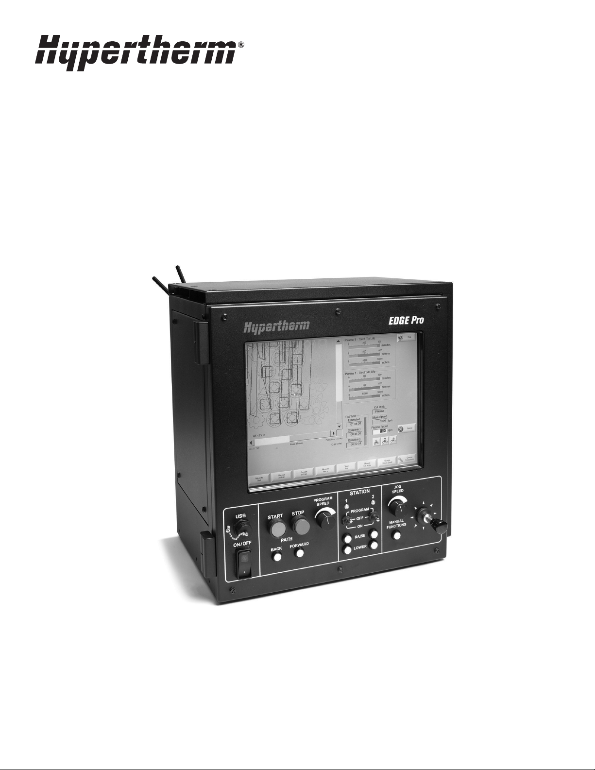
EDGE® Pro Picopath
Shape Cutting Control
Instruction Manual
807630 | Revision 4 | English

Register your new Hypertherm system
Register your product online at www.hypertherm.com/registration for easier technical
and warranty support. You can also receive updates on new Hypertherm products and a free
gift as a token of our appreciation.
For your records
Serial number:________________________________________________________________
Purchase date: _______________________________________________________________
Distributor: __________________________________________________________________
____________________________________________________________________________
____________________________________________________________________________
Maintenance notes:
____________________________________________________________________________
____________________________________________________________________________
____________________________________________________________________________
____________________________________________________________________________
____________________________________________________________________________
____________________________________________________________________________
ArcGlide, CutPro Wizard, EDGE, HPR, HSD, Hypernet, Hypertherm, Phoenix, Powermax, Sensor, and Watch Windows are
trademarks of Hypertherm Inc. and may be registered in the United States and other countries. All other trademarks are the property
of their respective holders.
One of Hypertherm's long-standing core values is a focus on minimizing our impact on the environment. Doing so is critical to our,
and our customers', success. We are always striving to become better environmental stewards; it is a process we care deeply about.
© 2015 Hypertherm Inc.

EDGE Pro Picopath CNC
Instruction Manual
807630
Revision 4
English
August 2015
Hypertherm Inc.
Hanover, NH 03755 USA
www.hypertherm.com

Hypertherm Inc.
Etna Road, P.O. Box 5010
Hanover, NH 03755 USA
603-643-3441 Tel (Main Office)
603-643-5352 Fax (All Departments)
info@hypertherm.com (Main Office Email)
800-643-9878 Tel (Technical Service)
technical.service@hypertherm.com (Technical Service Email)
800-737-2978 Tel (Customer Service)
customer.service@hypertherm.com (Customer Service Email)
866-643-7711 Tel (Return Materials Authorization)
877-371-2876 Fax (Return Materials Authorization)
return.materials@hypertherm.com (RMA email)
Hypertherm Plasmatechnik GmbH
Technologiepark Hanau
Rodenbacher Chaussee 6
D-63457 Hanau-Wolfgang, Deutschland
49 6181 58 2100 Tel
49 6181 58 2134 Fax
49 6181 58 2123 (Technical Service)
Hypertherm (S) Pte Ltd.
82 Genting Lane
Media Centre
Annexe Block #A01-01
Singapore 349567, Republic of Singapore
65 6841 2489 Tel
65 6841 2490 Fax
65 6841 2489 (Technical Service)
Hypertherm (Shanghai) Trading Co., Ltd.
Unit 301, South Building
495 ShangZhong Road
Shanghai, 200231
PR China
86-21-60740003 Tel
86-21-60740393 Fax
Hypertherm Europe B.V.
Vaartveld 9
4704 SE
Roosendaal, Nederland
31 165 596907 Tel
31 165 596901 Fax
31 165 596908 Tel (Marketing)
31 165 596900 Tel (Technical Service)
00 800 4973 7843 Tel (Technical Service)
Hypertherm Japan Ltd.
Level 9, Edobori Center Building
2-1-1 Edobori, Nishi-ku
Osaka 550-0002 Japan
81 6 6225 1183 Tel
81 6 6225 1184 Fax
Hypertherm Brasil Ltda.
Rua Bras Cubas, 231 – Jardim Maia
Guarulhos, SP - Brasil
CEP 07115-030
55 11 2409 2636 Tel
55 11 2408 0462 Fax
Hypertherm México, S.A. de C.V.
Avenida Toluca No. 444, Anexo 1,
Colonia Olivar de los Padres
Delegación Álvaro Obregón
México, D.F. C.P. 01780
52 55 5681 8109 Tel
52 55 5683 2127 Fax
Hypertherm Korea Branch
#3904 Centum Leaders Mark B/D,
1514 Woo-dong, Haeundae-gu, Busan
Korea, 612-889
82 51 747 0358 Tel
82 51 701 0358 Fax

Contents
Safety ....................................................................................................................................... SC-11
Recognize safety information ...............................................................................................................................................SC-11
Inspect equipment before using ..........................................................................................................................................SC-11
Follow safety instructions ......................................................................................................................................................SC-11
Responsibility for safety ........................................................................................................................................................SC-11
A plasma arc can damage frozen pipes ............................................................................................................................SC-11
Static electricity can damage printed circuit boards ......................................................................................................SC-11
Grounding safety ....................................................................................................................................................................SC-12
Electrical hazards ....................................................................................................................................................................SC-12
Electric shock can kill ............................................................................................................................................................SC-12
Cutting can cause fire or explosion ....................................................................................................................................SC-13
Fire prevention .................................................................................................................................................................SC-13
Explosion prevention ......................................................................................................................................................SC-13
Machine motion can cause injury ........................................................................................................................................SC-13
Compressed gas equipment safety ...................................................................................................................................SC-14
Gas cylinders can explode if damaged .............................................................................................................................SC-14
Toxic fumes can cause injury or death ...............................................................................................................................SC-14
A plasma arc can cause injury and burns .........................................................................................................................SC-15
Arc rays can burn eyes and skin .........................................................................................................................................SC-15
Pacemaker and hearing aid operation ...............................................................................................................................SC-15
Noise can damage hearing ...................................................................................................................................................SC-16
Dry dust collection information ............................................................................................................................................SC-16
Laser radiation .........................................................................................................................................................................SC-17
Additional safety information ................................................................................................................................................SC-17
EDGE Pro Picopath CNC Instruction Manual 807630 5

Contents
Product Stewardship ...........................................................................................................SC-19
Introduction ..............................................................................................................................................................................SC-19
National and local safety regulations .................................................................................................................................SC-19
Certification test marks .........................................................................................................................................................SC-19
Differences in national standards .......................................................................................................................................SC-19
Safe installation and use of shape cutting equipment ...................................................................................................SC-19
Procedures for periodic inspection and testing ..............................................................................................................SC-19
Qualification of test personnel .............................................................................................................................................SC-20
Residual current devices (RCDs) .......................................................................................................................................SC-20
Higher-level systems ..............................................................................................................................................................SC-20
Environmental Stewardship .............................................................................................. SC-21
Introduction ..............................................................................................................................................................................SC-21
National and local environmental regulations ...................................................................................................................SC-21
The RoHS directive ................................................................................................................................................................SC-21
Proper disposal of Hypertherm products ..........................................................................................................................SC-21
The WEEE Directive ..............................................................................................................................................................SC-21
The REACH regulation ..........................................................................................................................................................SC-21
Proper handling and safe use of chemicals .....................................................................................................................SC-22
Fumes emission and air quality ...........................................................................................................................................SC-22
Electromagnetic Compatibility (EMC) ............................................................................ SC-23
Introduction ..............................................................................................................................................................................SC-23
Installation and use .................................................................................................................................................................SC-23
Assessment of area ................................................................................................................................................................SC-23
Methods of reducing emissions ..........................................................................................................................................SC-23
Mains supply ....................................................................................................................................................................SC-23
Maintenance of cutting equipment .....................................................................................................................................SC-23
Cutting cables .........................................................................................................................................................................SC-23
Equipotential bonding ....................................................................................................................................................SC-23
Earthing of the workpiece .............................................................................................................................................SC-23
Screening and shielding .......................................................................................................................................................SC-24
6 EDGE Pro Picopath CNC Instruction Manual 807630

Contents
Warranty ..................................................................................................................................SC-25
Attention ....................................................................................................................................................................................SC-25
General .....................................................................................................................................................................................SC-25
Patent indemnity .....................................................................................................................................................................SC-25
Limitation of liability ................................................................................................................................................................SC-25
National and local codes .......................................................................................................................................................SC-25
Liability cap ..............................................................................................................................................................................SC-25
Insurance ..................................................................................................................................................................................SC-26
Transfer of rights .....................................................................................................................................................................SC-26
1 Specifications .............................................................................................................................. 27
Main features of an automated cutting system ...................................................................................................................... 27
CNC ......................................................................................................................................................................................... 29
Cutting table .......................................................................................................................................................................... 29
Cutting system ...................................................................................................................................................................... 29
Control box ............................................................................................................................................................................. 29
Drive system ........................................................................................................................................................................... 29
Torch height control ............................................................................................................................................................. 30
Operator console .................................................................................................................................................................. 30
Oxyfuel torch .......................................................................................................................................................................... 30
Marker ...................................................................................................................................................................................... 30
Overview ......................................................................................................................................................................................... 31
Features of the EDGE Pro Picopath CNC ............................................................................................................................. 32
Touchscreen .......................................................................................................................................................................... 32
Operator console .................................................................................................................................................................. 32
Rear panel .............................................................................................................................................................................. 33
System specifications .................................................................................................................................................................. 34
Picopath models ................................................................................................................................................................... 36
Integrated Sensor THC ....................................................................................................................................................... 37
Symbols and Marks ...................................................................................................................................................................... 38
2 Installation .................................................................................................................................... 39
Upon receipt .................................................................................................................................................................................. 39
Claims ...................................................................................................................................................................................... 39
Installation requirements ............................................................................................................................................................. 39
Placement of system components .................................................................................................................................... 40
Mounting the CNC ....................................................................................................................................................................... 40
Enclosure dimensions .......................................................................................................................................................... 41
Mounting hole patterns on the bottom of the CNC ...................................................................................................... 42
Recommended grounding and shielding practices .............................................................................................................. 43
Introduction ............................................................................................................................................................................ 43
EDGE Pro Picopath CNC Instruction Manual 807630 7

Contents
Types of grounding .............................................................................................................................................................. 43
Grounding practices ............................................................................................................................................................ 43
Grounding diagram .............................................................................................................................................................. 46
X and Y axis configuration .......................................................................................................................................................... 47
The operator console ................................................................................................................................................................... 48
Operator console and dedicated I/O ............................................................................................................................... 48
AC power ....................................................................................................................................................................................... 49
Power input ............................................................................................................................................................................ 49
Chassis grounding ............................................................................................................................................................... 50
Communication interfaces .......................................................................................................................................................... 51
Hypernet interface ................................................................................................................................................................ 51
LAN interface ......................................................................................................................................................................... 51
USB interface ........................................................................................................................................................................ 51
Serial ports ............................................................................................................................................................................. 51
Wireless antennas ................................................................................................................................................................ 51
Picopath I/O ................................................................................................................................................................................... 52
Picopath I/O circuit examples ............................................................................................................................................ 52
Picopath I/O connection ..................................................................................................................................................... 53
Picopath I/O cables ..................................................................................................................................................... 53
Picopath pinouts for 12 I/O ........................................................................................................................................ 54
Picopath drive/encoder connection ......................................................................................................................................... 55
Picopath drive/encoder cable ............................................................................................................................................ 55
Picopath drive/encoder connector ................................................................................................................................... 56
Picopath drive/encoder pinouts ........................................................................................................................................ 57
Integrated THC I/O configuration ............................................................................................................................................. 58
THC I/O Interface ................................................................................................................................................................. 58
THC I/O pinouts ................................................................................................................................................................... 58
THC cables ............................................................................................................................................................................ 59
J1 Power connector on VDC3 ................................................................................................................................... 59
Pinout for the cable between J2 on VDC3 and THC 1 or THC2 on the CNC .............................................. 59
J3 Field connector on VDC3 (black terminal strip) ............................................................................................... 59
8 EDGE Pro Picopath CNC Instruction Manual 807630

Contents
3 Operation ...................................................................................................................................... 61
Operating the CNC ...................................................................................................................................................................... 61
Touchscreen LCD ................................................................................................................................................................ 62
Touchscreens, drops of water, and unintended motion .............................................................................................. 62
Screen navigation ................................................................................................................................................................. 62
Help .......................................................................................................................................................................................... 63
View additional manuals ...................................................................................................................................................... 63
Show bookmarks .................................................................................................................................................................. 64
Automated operations ................................................................................................................................................................. 64
Align Wizard ........................................................................................................................................................................... 64
CutPro Wizard ....................................................................................................................................................................... 65
Updating Phoenix software ........................................................................................................................................................ 65
Updating the software ......................................................................................................................................................... 65
Updating the Help ................................................................................................................................................................ 65
Updating the cut charts ....................................................................................................................................................... 65
4 Maintenance and Diagnostics ................................................................................................ 67
Introduction .................................................................................................................................................................................... 67
Care and handling of the touchscreen .................................................................................................................................... 67
Diagnostic tests ............................................................................................................................................................................ 68
Machine interface tests ....................................................................................................................................................... 68
LAN and Hypernet tests ...................................................................................................................................................... 68
Serial test ................................................................................................................................................................................ 69
USB test ................................................................................................................................................................................. 69
I/O test .................................................................................................................................................................................... 70
Axis test ................................................................................................................................................................................... 70
THC test ................................................................................................................................................................................. 71
Operator console test .......................................................................................................................................................... 71
Troubleshooting ............................................................................................................................................................................ 73
Power ....................................................................................................................................................................................... 74
Operator console .................................................................................................................................................................. 74
Input failure ............................................................................................................................................................................. 75
Output failure ......................................................................................................................................................................... 75
Hypernet connection ............................................................................................................................................................ 75
LAN connection ..................................................................................................................................................................... 75
Motion issues ......................................................................................................................................................................... 76
THC 1 and THC 2 ................................................................................................................................................................ 77
Serial communication issues .............................................................................................................................................. 78
USB port ................................................................................................................................................................................. 78
Cut quality or plasma performance issues ...................................................................................................................... 79
The CNC feels excessively warm ...................................................................................................................................... 79
EDGE Pro Picopath CNC Instruction Manual 807630 9

Contents
Loading files ........................................................................................................................................................................... 79
Wireless troubleshooting .................................................................................................................................................... 80
Component locations and information ..................................................................................................................................... 81
Operator console board (141058) .......................................................................................................................................... 82
4-Axis MCC board (141061) .................................................................................................................................................... 84
Motherboard (141110) ............................................................................................................................................................... 87
4-Axis servo and 12 I/O board (141122) .............................................................................................................................. 88
Analog board (141125) .............................................................................................................................................................. 94
Surge board (141134) ................................................................................................................................................................ 95
Power distribution board (141153) ......................................................................................................................................... 96
2-Axis servo board (141254) .................................................................................................................................................... 98
Utility and serial isolation board (141307) ........................................................................................................................... 103
VDC for integrated Sensor THC (141201) ......................................................................................................................... 105
5 Parts List ..................................................................................................................................... 107
Diagnostic kits ............................................................................................................................................................................. 107
Cables ........................................................................................................................................................................................... 107
Cable connector kits .................................................................................................................................................................. 107
Picopath PCB kits ...................................................................................................................................................................... 108
Additional kits .............................................................................................................................................................................. 110
6 Wiring Diagrams ....................................................................................................................... 111
Wiring diagram symbols ........................................................................................................................................................... 112
Sheet 3 – EDGE Pro CNC with Picopath interface .......................................................................................................... 115
Sheet 5 – Power distribution board (141153) and surge board (141134) ................................................................. 116
Sheet 6 – Power distribution board, field and clean power out (J4 – J6) (141153) ................................................. 117
Sheet 7 – Operator console board (141058) ..................................................................................................................... 118
Sheet 8 – Operator console components (141058) ........................................................................................................ 119
Sheet 9 – Motherboard (141110) ......................................................................................................................................... 120
Sheet 10 – ATX power supply (229403) ............................................................................................................................. 121
Sheet 12 – Utility and serial isolation board (141307) ..................................................................................................... 122
Sheet 13 – 4- and 6-Axis MCC board (141061) .............................................................................................................. 123
Sheet 16 – Sensor THC analog board (141125) .............................................................................................................. 124
Sheet 17 – 2- and 4-Axis servo and 12 I/O boards (141254 and 141122) .............................................................. 125
10 EDGE Pro Picopath CNC Instruction Manual 807630

Safety
RECOGNIZE SAFETY INFORMATION
The symbols shown in this section are used to identify potential
hazards. When you see a safety symbol in this manual or on your
machine, understand the potential for personal injury, and follow the
related instructions to avoid the hazard.
FOLLOW SAFETY INSTRUCTIONS
Carefully read all safety messages in this manual and safety labels
on your machine.
• Keep the safety labels on your machine in good condition.
Replace missing or damaged labels immediately.
• Learn how to operate the machine and how to use the controls
properly. Do not let anyone operate it without instruction.
• Keep your machine in proper working condition. Unauthorized
modifications to the machine may affect safety and machine
service life.
RESPONSIBILITY FOR SAFETY
The person or entity responsible for the safety of the workplace must:
• Make sure that operators and their supervisors are trained in the safe
use of their equipment, the safe use of the process, and emergency
procedures.
• Make sure that all hazards and safety precautions identified herein
are communicated to and understood by workers before the start of
work.
• Designate approved cutting areas and establish procedures for safe
cutting.
• Be responsible for authorizing cutting operations in areas not
specifically designed or approved for such processes.
• Make sure that only approved equipment, such as torches and
personal protective equipment, are used.
DANGER WARNING CAUTION
American National Standards Institute (ANSI) guidelines are used for
safety signal words and symbols. The signal word DANGER or
WARNING is used with a safety symbol. DANGER identifies the most
serious hazards.
• DANGER and WARNING safety labels are located on your machine
near specific hazards.
• DANGER safety messages precede related instructions in the
manual that will result in serious injury or death if not followed
correctly.
• WARNING safety messages precede related instructions in this
manual that may result in injury or death if not followed correctly.
• CAUTION safety messages precede related instructions in this
manual that may result in minor injury or damage to equipment if not
followed correctly.
INSPECT EQUIPMENT BEFORE USING
All cutting equipment must be inspected as required to make sure it is in
safe operating condition. When found to be incapable of reliable and
safe operation, the equipment must be repaired by qualified personnel
prior to its next use or withdrawn from service.
• Select contractors who provide trained and qualified personnel, and
who have awareness of the risks involved, to do cutting.
• Tell contractors about flammable materials or hazardous conditions
that are specific to the site, or hazardous conditions that they may not
be aware of.
• Make sure that the quality and quantity of air for ventilation is such
that personnel exposures to hazardous contaminants are below the
allowable limits.
• Make sure that ventilation in confined spaces is sufficient to allow
adequate oxygen for life support, to prevent accumulation of
asphixiants or flammable explosive mixtures, to prevent
oxygen-enriched atmospheres, and to keep airborne contaminants in
breathing atmospheres below allowable limits.
A PLASMA ARC CAN DAMAGE FROZEN PIPES
Frozen pipes may be damaged or can burst if you attempt to thaw them with a plasma torch.
STATIC ELECTRICITY CAN DAMAGE PRINTED CIRCUIT BOARDS
Use proper precautions when handling printed circuit boards:
• Store printed circuit boards in anti-static containers.
• Wear a grounded wrist strap when handling printed circuit boards.
Safety and Compliance SC-11

Safety
GROUNDING SAFETY
Work lead Attach the work lead securely to the workpiece or the
cutting table with good metal-to-metal contact. Do not connect it to
the piece that will fall away when the cut is complete.
Cutting table Connect the cutting table to an earth ground, in
accordance with appropriate national and local electrical regulations.
ELECTRICAL HAZARDS
• Only trained and authorized personnel may open this equipment.
• If the equipment is permanently connected, turn it off, and lock
out/tag out power before the enclosure is opened.
• If power is supplied to the equipment with a cord, unplug the unit
before the enclosure is opened.
• Lockable disconnects or lockable plug covers must be provided by
others.
• Wait 5 minutes after removal of power before entering the enclosure
to allow stored energy to discharge.
ELECTRIC SHOCK CAN KILL
Input power
• Make sure to connect the power cord ground wire to the ground in
the disconnect box.
• If installation of the plasma system involves connecting the power
cord to the power supply, make sure to connect the power cord
ground wire properly.
• Place the power cord’s ground wire on the stud first, then place any
other ground wires on top of the power cord ground. Tighten the
retaining nut.
• Tighten all electrical connections to avoid excessive heating.
• If the equipment must have power when the enclosure is open for
servicing, arc flash explosion hazards may exist. Follow all local
requirements (NFPA 70E in the USA) for safe work practices and for
personal protective equipment when servicing energized equipment.
• Prior to operating the equipment after moving, opening, or servicing,
make sure to close the enclosure and make sure that there is proper
earth ground continuity to the enclosure.
• Always follow these instructions for disconnecting power before
inspecting or changing torch consumable parts.
Touching live electrical parts can cause a fatal shock or severe burn.
• Operating the plasma system completes an electrical circuit
between the torch and the workpiece. The workpiece and anything
touching the workpiece are part of the electrical circuit.
• In machine torch applications, never touch the torch body,
workpiece, or water in a water table when the plasma system is
operating.
Electric shock prevention
All plasma systems use high voltage in the cutting process
(200 to 400 VDC are common). Take the following
precautions when operating this system:
• Wear insulated gloves and boots, and keep your body and clothing
dry.
• Do not stand, sit, or lie on – or touch – any wet surface when using
the plasma system.
• Insulate yourself from the work and ground using dry insulating
mats or covers big enough to prevent any physical contact with the
work or ground. If you must cut in or near a damp area, use
extreme caution.
• Provide a disconnect switch close to the power supply with
properly sized fuses. This switch allows the operator to turn off the
power supply quickly in an emergency situation.
• When using a water table, make sure that it is correctly connected
to an earth ground.
• Install and ground this equipment according to the instruction
manual and in accordance with national and local regulations.
• Inspect the input power cord frequently for damage or cracking
of the cover. Replace a damaged power cord immediately.
Bare wiring can kill.
• Inspect and replace any worn or damaged torch leads.
• Do not pick up the workpiece, including the waste cutoff, while you
cut. Leave the workpiece in place or on the workbench with the
work lead attached during the cutting process.
• Before checking, cleaning, or changing torch parts, disconnect the
main power or unplug the power supply.
• Never bypass or shortcut the safety interlocks.
• Before removing any power supply or system enclosure cover,
disconnect electrical input power. Wait 5 minutes after
disconnecting the main power to allow capacitors to discharge.
• Never operate the plasma system unless the power supply covers
are in place. Exposed power supply connections present a severe
electrical hazard.
• When making input connections, attach a proper grounding
conductor first.
• Each plasma system is designed to be used only with specific
torches. Do not substitute other torches, which could overheat and
present a safety hazard.
SC-12 Safety and Compliance

CUTTING CAN CAUSE FIRE OR EXPLOSION
Safety
Fire prevention
• Make sure the cutting area is safe before doing any cutting. Keep a
fire extinguisher nearby.
• Remove all flammables within 35 feet (10 m) of the cutting area.
• Quench hot metal or allow it to cool before handling or before
letting it touch combustible materials.
• Never cut containers with potentially flammable materials inside –
they must be emptied and properly cleaned first.
• Ventilate potentially flammable atmospheres before cutting.
• When cutting with oxygen as the plasma gas, an exhaust ventilation
system is required.
Explosion prevention
• Do not use the plasma system if explosive dust or vapors may be
present.
• Do not cut pressurized cylinders, pipes, or any closed containers.
• Do not cut containers that have held combustible materials.
Explosion Hazard
Hydrogen Detonation with Aluminum Cutting
When you use a plasma torch to cut aluminum alloys under water or
on a water table, a chemical reaction between the water and the
workpiece, parts, fine particles, or molten aluminum droplets
generates significantly more hydrogen gas than occurs with other
metals. This hydrogen gas may get trapped under the workpiece. If
exposed to oxygen or air, the plasma arc or a spark from any source
can ignite this trapped hydrogen gas, causing an explosion that may
result in death, personal injury, loss of property, or equipment damage.
Consult with the table manufacturer and other experts prior to cutting
aluminum to implement a risk assessment and mitigation plan that
eliminates the risk of detonation by preventing hydrogen
accumulation.
WARNI NG
Explosion Hazard
Argon-Hydrogen and Methane
Hydrogen and methane are flammable gases that present an
explosion hazard. Keep flames away from cylinders and hoses that
contain methane or hydrogen mixtures. Keep flames and sparks away
from the torch when using methane or argon-hydrogen plasma.
WARNI NG
Explosion Hazard
Underwater Cutting with Fuel Gases
Containing Hydrogen
• Do not cut underwater with fuel gases containing hydrogen.
• Cutting underwater with fuel gases containing hydrogen can result
in an explosive condition that can detonate during plasma cutting
operations.
WARNI NG
Also, make sure that the water table, fume extraction (ventilation), and
other parts of the cutting system have been designed with aluminum
cutting in mind.
Do not cut aluminum alloys underwater or on a water table
unless you can prevent the accumulation of hydrogen gas.
Note: With proper mitigation, most aluminum alloys can be plasma
cut on a water table. An exception is aluminum-lithium alloys. Never
cut aluminum-lithium alloys in the presence of water. Contact
your aluminum supplier for additional safety information regarding
hazards associated with aluminum-lithium alloys.
MACHINE MOTION CAN CAUSE INJURY
When an original equipment manufacturer (OEM) makes a cutting system by combining Hypertherm equipment with other equipment, the end-use
customer and the OEM are responsible for providing protection against the hazardous moving parts of this cutting system. However, we advise the
following to prevent operator injury and equipment damage:
• Read and follow the instruction manual provided by the OEM.
• Maintain a restricted-access area larger than the maximum
movement range of the cutting system’s moving parts.
• Where there is a risk of collision, do not allow personnel or
equipment near the cutting system’s moving parts.
• Avoid accidental contact with the CNC touchscreen or joystick.
Accidental contact can activate commands and result in
unintended motion.
Safety and Compliance SC-13
• Do not service or clean the machinery during operation.
• If servicing is required, enable the safety interlock or disconnect
and lock out/tag out power to disable the motors and prevent
motion.
• Allow only qualified personnel to operate, maintain, and service
the machinery.

Safety
COMPRESSED GAS EQUIPMENT SAFETY
• Never lubricate cylinder valves or regulators with oil or grease.
• Use only correct gas cylinders, regulators, hoses, and fittings
designed for the specific application.
• Maintain all compressed gas equipment and associated parts in
good condition.
• Label and color-code all gas hoses to identify the type of gas in
each hose. Consult applicable national and local regulations.
TOXIC FUMES CAN CAUSE INJURY OR DEATH
The plasma arc by itself is the heat source used for cutting.
Accordingly, although the plasma arc has not been identified as a
source of toxic fumes, the material being cut can be a source of toxic
fumes or gases that deplete oxygen.
The fumes produced vary depending on the metal that is cut. Metals
that may release toxic fumes include, but are not limited to, stainless
steel, carbon steel, zinc (galvanized), and copper.
In some cases, the metal may be coated with a substance that could
release toxic fumes. Toxic coatings include, but are not limited to,
lead (in some paints), cadmium (in some paints and fillers), and
beryllium.
The gases produced by plasma cutting vary based on the material to
be cut and the method of cutting, but may include ozone, oxides of
nitrogen, hexavalent chromium, hydrogen, and other substances if
such are contained in or released by the material being cut.
Caution should be taken to minimize exposure to fumes produced by
any industrial process. Depending on the chemical composition and
concentration of the fumes (as well as other factors, such as
ventilation), there may be a risk of physical illness, such as birth
defects or cancer.
It is the responsibility of the equipment and site owner to test the air
quality in the cutting area and to make sure that the air quality in the
workplace meets all local and national standards and regulations.
GAS CYLINDERS CAN EXPLODE IF DAMAGED
Gas cylinders contain gas under high pressure. If damaged, a
cylinder can explode.
• Handle and use compressed gas cylinders in accordance with
applicable national and local regulations.
• Never use a cylinder that is not upright and secured in place.
• Keep the protective cap in place over the valve except when the
cylinder is in use or connected for use.
• Never allow electrical contact between the plasma arc and a
cylinder.
• Never expose cylinders to excessive heat, sparks, slag, or open
flame.
• Never use a hammer, wrench, or other tool to open a stuck cylinder
valve.
The air quality level in any relevant workplace depends on site-specific
variables such as:
• Table design (wet, dry, underwater).
• Material composition, surface finish, and composition of coatings.
• Volume of material removed.
• Duration of cutting or gouging.
• Size, air volume, ventilation, and filtration of the workplace.
• Personal protective equipment.
• Number of welding and cutting systems in operation.
• Other workplace processes that may produce fumes.
If the workplace must conform to national or local regulations, only
monitoring or testing done at the site can determine whether the
workplace is above or below allowable levels.
To reduce the risk of exposure to fumes:
• Remove all coatings and solvents from the metal before cutting.
• Use local exhaust ventilation to remove fumes from the air.
• Do not inhale fumes. Wear an air-supplied respirator when cutting
any metal coated with, containing, or suspected to contain toxic
elements.
• Make sure that those using welding or cutting equipment, as well as
air-supplied respiration devices, are qualified and trained in the
proper use of such equipment.
• Never cut containers with potentially toxic materials inside. Empty
and properly clean the container first.
• Monitor or test the air quality at the site as needed.
• Consult with a local expert to implement a site plan to make sure air
quality is safe.
SC-14 Safety and Compliance

A PLASMA ARC CAN CAUSE INJURY AND BURNS
Eye protection Plasma arc rays produce intense visible and invisible
(ultraviolet and infrared) rays that can burn eyes and skin.
• Use eye protection in accordance with applicable national and local
regulations.
• Wear eye protection (safety glasses or goggles with side shields,
and a welding helmet) with appropriate lens shading to protect your
eyes from the arc’s ultraviolet and infrared rays.
Skin protection Wear protective clothing to protect against burns
caused by ultraviolet light, sparks, and hot metal.
• Wear gauntlet gloves, safety shoes, and hat.
• Wear flame-retardant clothing to cover all exposed areas.
• Wear cuffless trousers to prevent entry of sparks and slag.
Also, remove any combustibles, such as a butane lighter or matches,
from your pockets before cutting.
Cutting area Prepare the cutting area to reduce reflection and
transmission of ultraviolet light:
• Paint walls and other surfaces with dark colors to reduce reflection.
• Use protective screens or barriers to protect others from flash
and glare.
• Warn others not to watch the arc. Use placards or signs.
Safety
Instant-on torches
A plasma arc ignites immediately when the torch switch is activated.
The plasma arc will cut quickly through gloves and skin.
• Keep away from the torch tip.
• Do not hold metal near the cutting path.
• Never point the torch toward yourself or others.
ARC RAYS CAN BURN EYES AND SKIN
Minimum protective
Arc current
Less than 40 A 5 5 8 9
41 A to 60 A 6 6 8 9
61 A to 80 A 8 8 8 9
81 A to 125 A 8 9 8 9
126 A to 150 A 8 9 8 10
151 A to 175 A 8 9 8 11
176 A to 250 A 8 9 8 12
251 A to 300 A 8 9 8 13
301 A to 400 A 9 12 9 13
401 A to 800 A101410N/A
shade number
(ANSIZ49.1:2012)
Suggested shade
number for comfort
(ANSI Z49.1:2012)
OSHA 29CFR
1910.133(a)(5)
Europe
EN168:2002
PACEMAKER AND HEARING AID OPERATION
Pacemaker and hearing aid operation can be affected by magnetic
fields from high currents.
Pacemaker and hearing aid wearers should consult a doctor before
going near any plasma arc cutting and gouging operations.
Safety and Compliance SC-15
To reduce magnetic field hazards:
• Keep both the work lead and the torch lead to one side, away from
your body.
• Route the torch leads as close as possible to the work lead.
• Do not wrap or drape the torch lead or work lead around your body.
• Keep as far away from the power supply as possible.

Safety
NOISE CAN DAMAGE HEARING
Cutting with a plasma arc can exceed acceptable noise levels as
defined by local regulations in many applications. Prolonged exposure
to excessive noise can damage hearing. Always wear proper ear
protection when cutting or gouging, unless sound pressure level
measurements taken at the site have verified personal hearing
protection is not necessary per relevant international, regional, and
local regulations.
Significant noise reduction can be obtained by adding simple
engineering controls to cutting tables such as barriers or curtains
positioned between the plasma arc and the workstation, and/or
locating the workstation away from the plasma arc. Implement
administrative controls in the workplace to restrict access and limit
operator exposure time, and screen off noisy areas and/or take
measures to reduce reverberation in cutting areas by putting up noise
absorbers.
DRY DUST COLLECTION INFORMATION
In some workplaces, dry dust can represent a potential explosion
hazard.
The U.S. National Fire Protection Association’s NFPA standard 68,
“Explosion Protection by Deflagration Venting,” provides requirements
for the design, location, installation, maintenance, and use of devices
and systems to vent combustion gases and pressures after any
deflagration event. Consult with the manufacturer or installer of any
dry dust collection system for applicable requirements before you
install a new dry dust collection system or make significant changes
in the process or materials used with an existing dry dust collection
system.
Consult your local “Authority Having Jurisdiction” (AHJ) to determine
whether any edition of NFPA standard 68 has been “adopted by
reference” in your local building codes.
Refer to NFPA standard 68 for definitions and explanations of
regulatory terms such as deflagration, AHJ, adopted by reference, the
Kst value, deflagration index, and other terms.
Use ear protectors if the noise is disruptive or if there is a risk of
hearing damage after all other engineering and administrative
controls have been implemented. If hearing protection is required,
wear only approved personal protective equipment such as ear muffs
or ear plugs with a noise reduction rating appropriate for the
situation. Warn others near the cutting area of possible noise
hazards. In addition, ear protection can prevent hot splatter from
entering the ear.
Note 1 – Unless a site-specific evaluation has been completed that
determines that none of the dust generated is combustible, then
NFPA standard 68 requires the use of explosion vents. Design the
explosion vent size and type to conform to the worst-case Kst value
as described in Annex F of NFPA standard 68. NFPA standard 68
does not specifically identify plasma cutting or other thermal cutting
processes as requiring deflagration venting systems, but it does
apply these new requirements to all dry dust collection systems.
Note 2 – Users should consult and comply with all applicable
national, state, and local regulations. Publications do not intend to
urge action that is not in compliance with all applicable regulations
and standards, and this manual may never be construed as doing so.
SC-16 Safety and Compliance
Safety
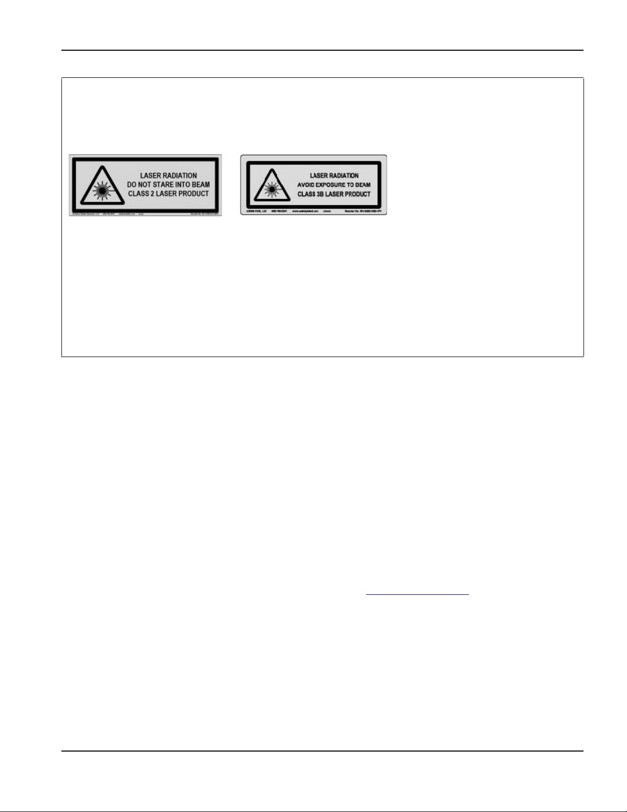
LASER RADIATION
Exposure to the laser beam from a laser pointer can result in serious eye injury. Avoid direct eye exposure.
On products that use a laser pointer for alignment, one of the following laser radiation labels has been applied on the product near where the laser
beam exits the enclosure. The maximum output (mV), wavelength emitted (nM), and, if appropriate, pulse duration are also provided.
Additional laser safety instructions:
• Consult with an expert on local laser regulations. Laser safety
training may be required.
• Do not allow untrained persons to operate the laser. Lasers can be
dangerous in the hands of untrained users.
• Do not look into the laser aperture or beam at any time.
• Position the laser as instructed to avoid unintentional eye contact.
• Do not use the laser on reflective workpieces.
• Do not use optical tools to view or reflect the laser beam.
• Do not disassemble or remove the laser or aperture cover.
ADDITIONAL SAFETY INFORMATION
1. ANSI Standard Z49.1, Safety in Welding and Cutting, American
Welding Society, 550 LeJeune Road, P.O. Box 351020, Miami,
FL 33135
2. ANSI Standard Z49.2, Fire Prevention in the Use of Cutting and
Welding Processes, American National Standards Institute,
1430 Broadway, New York, NY 10018
3. ANSI Standard Z87.1, Safe Practices for Occupation and
Educational Eye and Face Protection, American National
Standards Institute, 1430 Broadway, New York, NY 10018
4. AWS F4.1, Recommended Safe Practices for the Preparation
for Welding and Cutting of Containers and Piping That Have
Held Hazardous Substances, American Welding Society, 550
LeJeune Road, P.O. Box 351040, Miami, FL 33135
5. AWS F5.2, Recommended Safe Practices for Plasma Arc
Cutting, American Welding Society, 550 LeJeune Road,
P.O. Box 351040, Miami, FL 33135
• Modifying the laser or product in any way can increase the risk of
laser radiation.
• Use of adjustments or performance of procedures other than those
specified in this manual may result in hazardous laser radiation
exposure.
• Do not operate in explosive atmospheres, such as in the presence
of flammable liquids, gases, or dust.
• Use only laser parts and accessories that are recommended or
provided by the manufacturer for your model.
• Repairs and servicing must be performed by qualified personnel.
• Do not remove or deface the laser safety label.
6. CGA Pamphlet P-1, Safe Handling of Compressed Gases in
Cylinders, Compressed Gas Association, 1235 Jefferson Davis
Highway, Arlington, VA 22202
7. CSA Standard W117.2, Code for Safety in Welding and
Cutting, Canadian Standards Association Standard Sales,
178 Rexdale Boulevard, Rexdale, Ontario M9W 1R3, Canada
8. NFPA Standard 51B, Cutting and Welding Processes, National
Fire Protection Association, 1 Batterymarch Park, Quincy, MA
02169-7471
9. NFPA Standard 70, National Electrical Code, National Fire
Protection Association, 1 Batterymarch Park, Quincy, MA
02169-7471
10. OSHA, Safety and Health Standards, 29FR 1910 U.S.
Government Printing Office, Washington, D.C. 20402
11. AWS Safety and Health Fact Sheets, American Welding
Society, 550 LeJeune Road, P.O. Box 351040, Miami, FL
33135, www.aws.org/technical/facts/
Safety and Compliance SC-17

Safety
SC-18 Safety and Compliance

Product Stewardship
Introduction
Hypertherm maintains a global Regulatory Management System to
ensure that products comply with regulatory and environmental
requirements.
National and local safety regulations
National and Local safety regulations shall take precedence over any
instructions provided with the product. The product shall be imported,
installed, operated and disposed of in accordance with national and local
regulations applicable to the installed site.
Certification test marks
Certified products are identified by one or more certification test marks
from accredited testing laboratories. The certification test marks are
located on or near the data plate.
Each certification test mark means that the product and its safety-critical
components conform to the relevant national safety standards as
reviewed and determined by that testing laboratory. Hypertherm places
a certification test mark on its products only after that product is
manufactured with safety-critical components that have been authorized
by the accredited testing laboratory.
Once the product has left the Hypertherm factory, the certification test
marks are invalidated if any of the following occurs:
• The product is modified in a manner that creates a hazard or
non-conformance with the applicable standards.
• Safety-critical components are replaced with unauthorized spare
parts.
• Any unauthorized assembly, or accessory that uses or generates a
hazardous voltage is added.
• There is any tampering with a safety circuit or other feature that is
designed into the product as part of the certification, or otherwise.
CE marking constitutes a manufacturer’s declaration of conformity to
applicable European directives and standards. Only those versions of
Hypertherm products with a CE Marking located on or near the data
plate have been tested for compliance with the European Low Voltage
Directive and the European EMC Directive. EMC filters needed to
comply with the European EMC Directive are incorporated within
versions of the power supply with a CE Marking.
Certificates of compliance for Hypertherm products are available from
the Downloads Library on the Hypertherm web site at
https://www.hypertherm.com
.
Differences in national standards
Nations may apply different performance, safety or other standards.
National differences in standards include, but are not limited to:
•Voltages
• Plug and cord ratings
• Language requirements
• Electromagnetic compatibility requirements
These differences in national or other standards may make it impossible
or impractical for all certification test marks to be placed on the same
version of a product. For example, the CSA versions of Hypertherm’s
products do not comply with European EMC requirements, and therefore
do not have a CE marking on the data plate.
Countries that require CE marking or have compulsory EMC regulations
must use CE versions of Hypertherm products with the CE marking on
the data plate. These include, but are not limited to:
•Australia
• New Zealand
• Countries in the European Union
• Russia
It is important that the product and its certification test mark be suitable
for the end-use installation site. When Hypertherm products are shipped
to one country for export to another country; the product must be
configured and certified properly for the end-use site.
Safe installation and use of shape cutting equipment
IEC 60974-9, titled Arc Welding Equipment – Installation and use,
provides guidance in the safe installation and use of shape cutting
equipment and the safe performance of cutting operations. The
requirements of national and local regulations shall be taken into
consideration during installation, including, but not limited to, grounding
or protective earth connections, fuses, supply disconnecting device, and
type of supply circuit. Read these instructions before installing the
equipment. The first and most important step is the safety assessment of
the installation.
The safety assessment must be performed by an expert, and determines
what steps are necessary to create a safe environment, and what
precautions should be adopted during the actual installation and
operation.
Procedures for periodic inspection and testing
Where required by local national regulations, IEC 60974-4 specifies test
procedures for periodic inspection and after repair or maintenance, to
ensure electrical safety for plasma cutting power sources built in
conformity with IEC 60974-1. Hypertherm performs the continuity of the
protective circuit and insulation resistance tests in the factory as
non-operating tests. The tests are performed with the power and ground
connections removed.
Safety and Compliance SC-19

Product Stewardship
Hypertherm also removes some protective devices that would cause
false test results. Where required by local national regulations, a label
shall be attached to the equipment to indicate that it has passed the
tests prescribed by IEC 60974-4. The repair report shall indicate the
results of all tests unless an indication is made that a particular test has
not been performed.
Qualification of test personnel
Electrical safety tests for shape cutting equipment can be hazardous and
shall be carried out by an expert in the field of electrical repair, preferably
someone also familiar with welding, cutting, and allied processes. The
safety risks to personnel and equipment, when unqualified personnel are
performing these tests, may be much greater than the benefit of periodic
inspection and testing.
Hypertherm recommends that only visual inspection be performed unless
the electrical safety tests are specifically required by local national
regulations in the country where the equipment is installed.
Residual current devices (RCDs)
In Australia and some other countries, local codes may require the use of
a Residual Current Devices (RCD) when portable electrical equipment is
used in the workplace or at construction sites to protect operators from
electrical faults in the equipment. RCDs are designed to safely
disconnect the mains electrical supply when an imbalance is detected
between the supply and return current (there is a leakage current to
earth). RCDs are available with both fixed and adjustable trip currents
between 6 to 40 milliamperes and a range of trip times up to
300 milliseconds selected for the equipment installation, application and
intended use. Where RCDs are used, the trip current and trip time on
RCDs should be selected or adjusted high enough to avoid nuisance
tripping during normal operation of the plasma cutting equipment and
low enough in the extremely unlikely event of an electrical fault in the
equipment to disconnect the supply before the leakage current under a
fault condition can pose a life threatening electrical hazard to operators.
To verify that the RCDs continue to function properly over time, both the
trip current and the trip time should be tested periodically. Portable
electrical equipment and RCDs used in commercial and industrial areas
in Australia and New Zealand are tested to the Australian standard
AS/NZS 3760. When you test the insulation of plasma cutting
equipment to AS/NZS 3760, measure the insulation resistance
according to Appendix B of the standard, at 250 VDC with the power
switch in the ON position to verify proper testing and to avoid the false
failure of the leakage current test. False failures are possible because the
metal oxide varistors (MOVs) and electromagnetic compatibility (EMC)
filters, used to reduce emissions and protect the equipment from power
surges, may conduct up to 10 milliamperes leakage current to earth
under normal conditions.
If you have any questions regarding the application or interpretation of
any IEC standards described here, you are required to consult with an
appropriate legal or other advisor familiar with the International
Electrotechnical standards, and shall not rely on Hypertherm in any
respect regarding the interpretation or application of such standards.
Higher-level systems
When a system integrator adds additional equipment; such as cutting
tables, motor drives, motion controllers or robots; to a Hypertherm
plasma cutting system, the combined system may be considered a
higher-level system. A higher-level system with hazardous moving parts
may constitute industrial machinery or robotic equipment, in which case
the OEM or end-use customer may be subject to additional regulations
and standards than those relevant to the plasma cutting system as
manufactured by Hypertherm.
It is the responsibility of the end-use customer and the OEM to perform a
risk assessment for the higher-level system, and to provide protection
against hazardous moving parts. Unless the higher-level system is
certified when the OEM incorporates Hypertherm products into it, the
installation also may be subject to approval by local authorities. Seek
advice from legal counsel and local regulatory experts if you are uncertain
about compliance.
External interconnecting cables between component parts of the higher
level system must be suitable for contaminants and movement as
required by the final end use installation site. When the external
interconnecting cables are subject to oil, dust, water, or other
contaminants, hard usage ratings may be required.
When external interconnecting cables are subject to continuous
movement, constant flexing ratings may be required. It is the
responsibility of the end-use customer or the OEM to ensure the cables
are suitable for the application. Since there are differences in the ratings
and costs that can be required by local regulations for higher level
systems, it is necessary to verify that any external interconnecting cables
are suitable for the end-use installation site.
SC-20 Safety and Compliance

Environmental Stewardship
Introduction
The Hypertherm Environmental Specification requires RoHS, WEEE and
REACH substance information to be provided by Hypertherm’s
suppliers.
Product environmental compliance does not address the indoor air
quality or environmental release of fumes by the end user. Any materials
that are cut by the end user are not provided by Hypertherm with the
product. The end user is responsible for the materials being cut as well
as for safety and air quality in the workplace. The end user must be aware
of the potential health risks of the fumes released from the materials
being cut and comply with all local regulations.
National and local environmental regulations
National and local environmental regulations shall take precedence over
any instructions contained in this manual.
The product shall be imported, installed, operated and disposed of in
accordance with all national and local environmental regulations
applicable to the installed site.
The European Environmental regulations are discussed later in
The WEEE Directive.
The RoHS directive
Hypertherm is committed to complying with all applicable laws and
regulations, including the European Union Restriction of Hazardous
Substances (RoHS) Directive that restricts the use of hazardous
materials in electronics products. Hypertherm exceeds RoHS Directive
compliance obligations on a global basis.
Hypertherm continues to work toward the reduction of RoHS materials in
our products, which are subject to the RoHS Directive, except where it is
widely recognized that there is no feasible alternative.
Declarations of RoHS Conformity have been prepared for the current
CE versions of Powermax plasma cutting systems manufactured by
Hypertherm. There is also a “RoHS mark” on the Powermax CE versions
below the “CE Marking” on the data plate of CE versions of Powermax
series units shipped since 2006. Parts used in CSA versions of
Powermax and other products manufactured by Hypertherm that are
either out of scope or exempt from RoHS are continuously being
converted to RoHS compliance in anticipation of future requirements.
Proper disposal of Hypertherm products
Hypertherm plasma cutting systems, like all electronic products, may
contain materials or components, such as printed circuit boards, that
cannot be discarded with ordinary waste. It is your responsibility to
dispose of any Hypertherm product or component part in an
environmentally acceptable manner according to national and local
codes.
• In the United States, check all federal, state, and local laws.
• In the European Union, check the EU directives, national, and local
laws. For more information, visit www.hypertherm.com/weee
• In other countries, check national and local laws.
• Consult with legal or other compliance experts when appropriate.
.
The WEEE Directive
On January 27, 2003, the European Parliament and the Council of the
European Union authorized Directive 2002/96/EC or WEEE (Waste
Electrical and Electronic Equipment).
As required by the legislation, any Hypertherm product covered by the
directive and sold in the EU after August 13, 2005 is marked with the
WEEE symbol. This directive encourages and sets specific criteria for
the collection, handling, and recycling of EEE waste. Consumer and
business-to-business wastes are treated differently (all Hypertherm
products are considered business-to-business). Disposal instructions for
the CE versions of Powermax plasma systems can be found at
www.hypertherm.com/weee
The URL is printed on the symbol-only warning label for each of these
CE version Powermax series units shipped since 2006. The CSA
versions of Powermax and other products manufactured by Hypertherm
are either out of scope or exempt from WEEE.
.
The REACH regulation
The REACH regulation (1907/2006), in force since June1, 2007, has an
impact on chemicals available to the European market. The REACH
regulation requirements for component manufacturers states that the
component shall not contain more than 0.1% by weight of the
Substances of Very High Concern (SVHC).
Component manufacturers and other downstream users, such as
Hypertherm, are obligated to obtain assurances from its suppliers that all
chemicals used in or on Hypertherm products will have a European
Chemical Agency (ECHA) registration number. To provide chemical
information as required by the REACH regulation, Hypertherm requires
suppliers to provide REACH declarations and identify any known use of
REACH SVHC. Any use of SVHC in amounts exceeding 0.1% w/w of
the parts has been eliminated. The MSDS contains a full disclosure of all
substances in the chemical and can be used to verify REACH SVHC
compliance.
The lubricants, sealants, coolants, adhesives, solvents, coatings and
other preparations or mixtures used by Hypertherm in, on, for, or with its
shape cutting equipment are used in very small quantities (except the
coolant) and are commercially available with multiple sources that can
and will be replaced in the event of a supplier problem associated with
REACH Registration or REACH Authorization (SVHCs).
Safety and Compliance SC-21

Environmental Stewardship
Proper handling and safe use of chemicals
Chemical Regulations in the USA, Europe, and other locations require
that Material Safety Data Sheets (MSDS) be made available for all
chemicals. The list of chemicals is provided by Hypertherm. The MSDS
are for chemicals provided with the product and other chemicals used in
or on the product. MSDS can be downloaded from the Downloads
Library on the Hypertherm web site at https://www.hypertherm.com
On the Search screen, insert MSDS in the document title and click on
Search.
In the USA, OSHA does not require Material Safety Data Sheets for
articles such as electrodes, swirl rings, retaining caps, nozzles, shields,
deflectors and other solid parts of the torch.
Hypertherm does not manufacture or provide the materials that are cut
and has no knowledge whether the fumes released from materials that
are cut will pose a physical hazard or health risk. Please consult with your
supplier or other technical advisor if you need guidance concerning the
properties of the material you will cut using a Hypertherm product.
.
Fumes emission and air quality
Note: The following information on air quality is intended for general
information only and should not be used as a substitute for reviewing and
implementing applicable government regulations or legal standards in
the country where the cutting equipment will be installed and operated.
In the USA, the National Institute for Occupational Safety and Health
(NIOSH) Manual of Analytical Methods (NMAM) is a collection of
methods for sampling and analyzing contaminants in workplace air.
Methods published by others, such as OSHA, MSHA, EPA, ASTM, ISO
or commercial suppliers of sampling and analytical equipment, may have
advantages over NIOSH methods.
For example, ASTM Practice D 4185 is a standard practice for the
collection, dissolution, and determination of trace metals in workplace
atmospheres. The sensitivity, detection limit, and optimum working
concentrations for 23 metals are listed in ASTM D 4185. An industrial
hygienist should be used to determine the optimum sampling protocol,
considering analytical accuracy, cost, and optimum sample number.
Hypertherm uses a third party industrial hygienist to perform and interpret
air quality testing results taken by air sampling equipment positioned at
operator stations in Hypertherm buildings where plasma cutting tables
are installed and operated.
Where applicable, Hypertherm also uses a third party industrial hygienist
to obtain air and water permits.
If you are not fully aware and up to date on all applicable government
regulations and legal standards for the installation site, you should
consult a local expert prior to purchasing, installing, and operating the
equipment.
SC-22 Safety and Compliance

Electromagnetic Compatibility (EMC)
Introduction
Hypertherm’s CE-marked equipment is built in compliance with standard
EN60974-10. The equipment should be installed and used in
accordance with the information below to achieve electromagnetic
compatibility.
The limits required by EN60974-10 may not be adequate to completely
eliminate interference when the affected equipment is in close proximity
or has a high degree of sensitivity. In such cases it may be necessary to
use other measures to further reduce interference.
This cutting equipment is designed for use only in an industrial
environment.
Installation and use
The user is responsible for installing and using the plasma equipment
according to the manufacturer’s instructions.
If electromagnetic disturbances are detected then it shall be the
responsibility of the user to resolve the situation with the technical
assistance of the manufacturer. In some cases this remedial action may
be as simple as earthing the cutting circuit, see Earthing of the
workpiece. In other cases, it could involve constructing an
electromagnetic screen enclosing the power source and the work
complete with associated input filters. In all cases, electromagnetic
disturbances must be reduced to the point where they are no longer
troublesome.
Methods of reducing emissions
Mains supply
Cutting equipment must be connected to the mains supply according to
the manufacturer’s recommendations. If interference occurs, it may be
necessary to take additional precautions such as filtering of the mains
supply.
Consideration should be given to shielding the supply cable of
permanently installed cutting equipment, in metallic conduit or
equivalent. Shielding should be electrically continuous throughout its
length. The shielding should be connected to the cutting mains supply so
that good electrical contact is maintained between the conduit and the
cutting power source enclosure.
Maintenance of cutting equipment
The cutting equipment must be routinely maintained according to the
manufacturer’s recommendations. All access and service doors and
covers should be closed and properly fastened when the cutting
equipment is in operation. The cutting equipment should not be modified
in any way, except as set forth in and in accordance with the
manufacturer’s written instructions. For example, the spark gaps of arc
striking and stabilizing devices should be adjusted and maintained
according to the manufacturer’s recommendations.
Cutting cables
Assessment of area
Before installing the equipment, the user shall make an assessment of
potential electromagnetic problems in the surrounding area. The
following shall be taken into account:
a. Other supply cables, control cables, signaling and telephone
cables; above, below and adjacent to the cutting equipment.
b. Radio and television transmitters and receivers.
c. Computer and other control equipment.
d. Safety critical equipment, for example guarding of industrial
equipment.
e. Health of the people around, for example the use of pacemakers
and hearing aids.
f. Equipment used for calibration or measurement.
g. Immunity of other equipment in the environment. User shall
ensure that other equipment being used in the environment is
compatible. This may require additional protection measures.
h. Time of day that cutting or other activities are to be carried out.
The size of the surrounding area to be considered will depend on the
structure of the building and other activities that are taking place. The
surrounding area may extend beyond the boundaries of the premises.
The cutting cables should be kept as short as possible and should be
positioned close together, running at or close to the floor level.
Equipotential bonding
Bonding of all metallic components in the cutting installation and
adjacent to it should be considered.
However, metallic components bonded to the workpiece will increase
the risk that the operator could receive a shock by touching these
metallic components and the electrode (nozzle for laser heads) at the
same time.
The operator should be insulated from all such bonded metallic
components.
Earthing of the workpiece
Where the workpiece is not bonded to earth for electrical safety, nor
connected to earth because of its size and position, for example, ship’s
hull or building steel work, a connection bonding the workpiece to earth
may reduce emissions in some, but not all instances. Care should be
taken to prevent the earthing of the workpiece increasing the risk of injury
to users, or damage to other electrical equipment. Where necessary, the
connection of the workpiece to earth should be made by a direct
connection to the workpiece, but in some countries where direct
connection is not permitted, the bonding should be achieved by suitable
capacitances selected according to national regulations.
Safety and Compliance SC-23

Electromagnetic Compatibility (EMC)
Note: The cutting circuit may or may not be earthed for safety reasons.
Changing the earthing arrangements should only be authorized by a
person who is competent to assess whether the changes will in crease
the risk of injury, for example, by allowing parallel cutting current return
paths which may damage the earth circuits of other equipment. Further
guidance is provided in IEC 60974-9, Arc Welding Equipment, Part 9:
Installation and Use.
Screening and shielding
Selective screening and shielding of other cables and equipment in the
surrounding area may alleviate problems of interference. Screening of the
entire plasma cutting installation may be considered for special
applications.
SC-24 Safety and Compliance

Warranty
Attention
Genuine Hypertherm parts are the factory-recommended replacement
parts for your Hypertherm system. Any damage or injury caused by the
use of other than genuine Hypertherm parts may not be covered by the
Hypertherm warranty, and will constitute misuse of the Hypertherm
Product.
You are solely responsible for the safe use of the Product. Hypertherm
does not and cannot make any guarantee or warranty regarding the safe
use of the product in your environment.
General
Hypertherm Inc. warrants that its Products shall be free from defects in
materials and workmanship for the specific periods of time set forth
herein and as follows: if Hypertherm is notified of a defect (i) with respect
to the plasma power supply within a period of two (2) years from the date
of its delivery to you, with the exception of Powermax brand power
supplies, which shall be within a period of three (3) years from the date of
delivery to you, and (ii) with respect to the torch and leads within a period
of one (1) year from its date of delivery to you, with the exception of the
HPRXD short torch with integrated lead, which shall be within a period of
six (6) months from the date of delivery to you, and with respect to torch
lifter assemblies within a period of one (1) year from its date of delivery to
you, and with respect to Automation products one (1) year from its date
of delivery to you, with the exception of the EDGE Pro CNC,
EDGE Pro Ti CNC, MicroEDGE Pro CNC, and ArcGlide THC, which
shall be within a period of two (2) years from the date of delivery to you,
and (iii) with respect to HyIntensity fiber laser components within a
period of two (2) years from the date of its delivery to you, with the
exception of laser heads and beam delivery cables, which shall be within
a period of one (1) year from its date of delivery to you.
This warranty shall not apply to any Powermax brand power supplies that
have been used with phase converters. In addition, Hypertherm does not
warranty systems that have been damaged as a result of poor power
quality, whether from phase converters or incoming line power. This
warranty shall not apply to any product which has been incorrectly
installed, modified, or otherwise damaged.
Hypertherm provides repair, replacement or adjustment of the Product as
the sole and exclusive remedy, if and only if the warranty set forth herein
properly is invoked and applies. Hypertherm, at its sole option, shall
repair, replace, or adjust, free of charge, any defective Products covered
by this warranty which shall be returned with Hypertherm’s prior
authorization (which shall not be unreasonably withheld), properly
packed, to Hypertherm’s place of business in Hanover, New Hampshire,
or to an authorized Hypertherm repair facility, all costs, insurance and
freight pre paid by the customer. Hypertherm shall not be liable for any
repairs, replacement, or adjustments of Products covered by this
warranty, except those made pursuant to this paragraph and with
Hypertherm’s prior written consent.
The warranty set forth above is exclusive and is in lieu of all other
warranties, express, implied, statutory, or otherwise with respect to the
Products or as to the results which may be obtained therefrom, and all
implied warranties or conditions of quality or of merchantability or fitness
for a particular purpose or against infringement. The foregoing shall
constitute the sole and exclusive remedy for any breach by Hypertherm
of its warranty.
Distributors/OEMs may offer different or additional warranties, but
Distributors/OEMs are not authorized to give any additional warranty
protection to you or make any representation to you purporting to be
binding upon Hypertherm.
Patent indemnity
Except only in cases of products not manufactured by Hypertherm or
manufactured by a person other than Hypertherm not in strict conformity
with Hypertherm’s specifications and in cases of designs, processes,
formulae, or combinations not developed or purported to be developed
by Hypertherm, Hypertherm will have the right to defend or settle, at its
own expense, any suit or proceeding brought against you alleging that
the use of the Hypertherm product, alone and not in combination with
any other product not supplied by Hypertherm, infringes any patent of
any third party. You shall notify Hypertherm promptly upon learning of any
action or threatened action in connection with any such alleged
infringement (and in any event no longer than fourteen (14) days after
learning of any action or threat of action), and Hypertherm’s obligation to
defend shall be conditioned upon Hypertherm’s sole control of, and the
indemnified party’s cooperation and assistance in, the defense of the
claim.
Limitation of liability
In no event shall Hypertherm be liable to any person or entity for
any incidental, consequential direct, indirect, punitive or
exemplary damages (including but not limited to lost profits)
regardless of whether such liability is based on breach of
contract, tort, strict liability, breach of warranty, failure of
essential purpose, or otherwise, and even if advised of the
possibility of such damages.
National and local codes
National and local codes governing plumbing and electrical installation
shall take precedence over any instructions contained in this manual.
In no event shall Hypertherm be liable for injury to persons or property
damage by reason of any code violation or poor work practices.
Liability cap
In no event shall Hypertherm’s liability, if any, whether such
liability is based on breach of contract, tort, strict liability,
breach of warranties, failure of essential purpose or otherwise,
for any claim, action, suit or proceeding (whether in court,
arbitration, regulatory proceeding or otherwise) arising out of or
relating to the use of the Products exceed in the aggregate the
amount paid for the Products that gave rise to such claim.
Safety and Compliance SC-25

Warranty
Insurance
At all times you will have and maintain insurance in such quantities and
types, and with coverage sufficient and appropriate to defend and to hold
Hypertherm harmless in the event of any cause of action arising from the
use of the products.
Transfer of rights
You may transfer any remaining rights you may have hereunder only in
connection with the sale of all or substantially all of your assets or capital
stock to a successor in interest who agrees to be bound by all of the
terms and conditions of this Warranty. Within thirty (30) days before any
such transfer occurs, you agree to notify in writing Hypertherm, which
reserves the right of approval. Should you fail timely to notify Hypertherm
and seek its approval as set forth herein, the Warranty set forth herein
shall be null and void and you will have no further recourse against
Hypertherm under the Warranty or otherwise.
SC-26 Safety and Compliance

Section 1
Optional operator
console
Cutting table
Control box
Drive amplifier
Oxyfuel cutting
system
EDGE Pro
Picopath
CNC
THC
Cutting system
(plasma, laser,
waterjet, marking)
Products available from Hypertherm
Specifications
Main features of an automated cutting system
Figure 1 illustrates the relationship between the components of an automated cutting system. The following topics
describe these components and their relationships.
Figure 1 Components of an automated cutting system
EDGE Pro Picopath CNC Instruction Manual 807630 27

1 – Specifications
987
6
5
4
3
2
1
Plasma system
2
Cutting table
3
Workpiece
4
Lifter
5
Gantry
6
Star ground
7
Rails
8
Operator console
9
EDGE Pro Picopath CNC
Main features of an automated cutting system
Figure 2 illustrates a typical cutting table with an EDGE Pro CNC and other components that are described in the
following topics.
Figure 2 Illustration of a plasma cutting table
1
28 EDGE Pro Picopath CNC Instruction Manual 807630

1 – Specifications
Main features of an automated cutting system
CNC
The computerized numerical control (CNC) reads part programs and communicates with the other components of the
shape cutting system. It controls which parts (shapes) are cut from the workpiece.
Refer to the sections in this manual for more detailed information about the hardware features of the EDGE Pro Picopath
CNC. Refer to the following Phoenix™ software manuals for detailed information on the software that operates on the
EDGE Pro Picopath CNC:
• Phoenix Software V9 Series Installation and Setup Manual (806410)
• Phoenix Software Operator Manual (806400)
• Phoenix Software V9 Series Programmer’s Reference (806420)
Cutting table
The cutting table is the frame that supports the workpiece from which parts are cut. A typical cutting table has two rails
that run the length of the table on either side and form the track for the gantry. The gantry rides along these rails and
spans the width of the table. A torch height control (THC) is attached to the gantry and provides the vertical movement of
the cutting torch. The horizontal motion of the gantry and torch station, and the vertical motion of the torch on the THC
provide the three axes that are necessary for controlling the torch’s position on the workpiece. Additional equipment can
be included on the cutting table to permit bevel and other types of cutting.
Hypertherm does not manufacture cutting tables. For more information on the cutting table in your system, refer to the
manual that the table manufacturer supplied.
Cutting system
The cutting tool is the heart of any cutting system and may be a plasma, oxyfuel, laser, or waterjet system. The cutting
system controls key parameters, such as the plasma gas and assist gases, and controls how they are mixed. It also
provides process parameters, such as standoff and speed for optimal cut quality.
Your cutting system may include a Hypertherm cutting system. Refer to the appropriate manual for additional information.
Electronic (PDF) versions of Hypertherm manuals are available at https://www.hypertherm.com or on the CNC. If your
cutting system is manufactured by another company, refer to the appropriate manual.
Control box
The control box (supplied by the table manufacturer) contains terminal blocks that route power and control signals to the
subsystems of the cutting system. The control box may also contain the drive amplifiers that amplify control signals from
the CNC to the motors for motion.
Drive system
The speed, smoothness, and accuracy of the cuts are determined by the combination of the CNC, encoders, servo drive
amplifiers, THC, gears, rails, servo motors, and how well they are integrated (tuned) by the table manufacturer. The table
manufacturer must select and install the drives and motors that will be used with the EDGE Pro Picopath CNC. For more
information on the drive system for your cutting system, refer to the manual that the table manufacturer supplied.
EDGE Pro Picopath CNC Instruction Manual 807630 29

1 – Specifications
Main features of an automated cutting system
Torch height control
The THC controls the distance between the torch and the workpiece, also known as the standoff. This standoff is usually
defined by height or voltage.
If a Hypertherm THC is part of your system, consult one of the following manuals for more information about installing and
using it:
®
•ArcGlide
•Sensor
THC (806450)
™
THC (806400, 806410, and 806420)
• Sensor PHC (806150)
If your THC is manufactured by another company, refer to the manual that the table manufacturer supplied.
Operator console
The EDGE Pro Picopath operator console controls two cutting stations. Additional operator consoles, not manufactured
by Hypertherm, may be installed by the table manufacturer to control oxyfuel, markers, ventilation systems, and other
devices. For more information about an optional operator console, refer to the manual that the table manufacturer
supplied.
Oxyfuel torch
Automated cutting systems can also be configured with oxyfuel torches with or without an oxygen height control (OHC).
If the Hypertherm Sensor™ OHC is configured in your system, refer to the Sensor OHC manual (MANU–0044) for
information about installation and operation.
For more information about any other oxyfuel torch, refer to the manual that the table manufacturer supplied.
Marker
A marker can be any device or process that marks a workpiece rather than piercing or cutting it. If the Hypertherm
ArcWriter
operation. Any HPR
HPR manual.
For other devices or processes, refer to the manual that the table manufacturer supplied.
®
is configured in your system, refer to the ArcWriter manual (802520) for information about installation and
®
plasma system can also be used for marking. For more information, refer to the appropriate
30 EDGE Pro Picopath CNC Instruction Manual 807630

1 – Specifications
2-Station operator console
Touchscreen
Overview
Overview
The EDGE Pro Picopath is a PC-based CNC and uses Hypertherm’s Phoenix software to control one or more cutting or
marking stations.
®
The EDGE Pro Picopath CNC has a two-station operator console, a 15-inch touchscreen, and Hypernet
wireless LAN communication.
EDGE Pro Picopath CNC features can be configured with multiple drive axes, integrated Sensor THC interface, bevel
head control, and networking to download part programs or to support remote diagnostic utilities.
, Ethernet, and
Figure 3 Front view of the EDGE
Pro Picopath CNC
EDGE Pro Picopath CNC Instruction Manual 807630 31
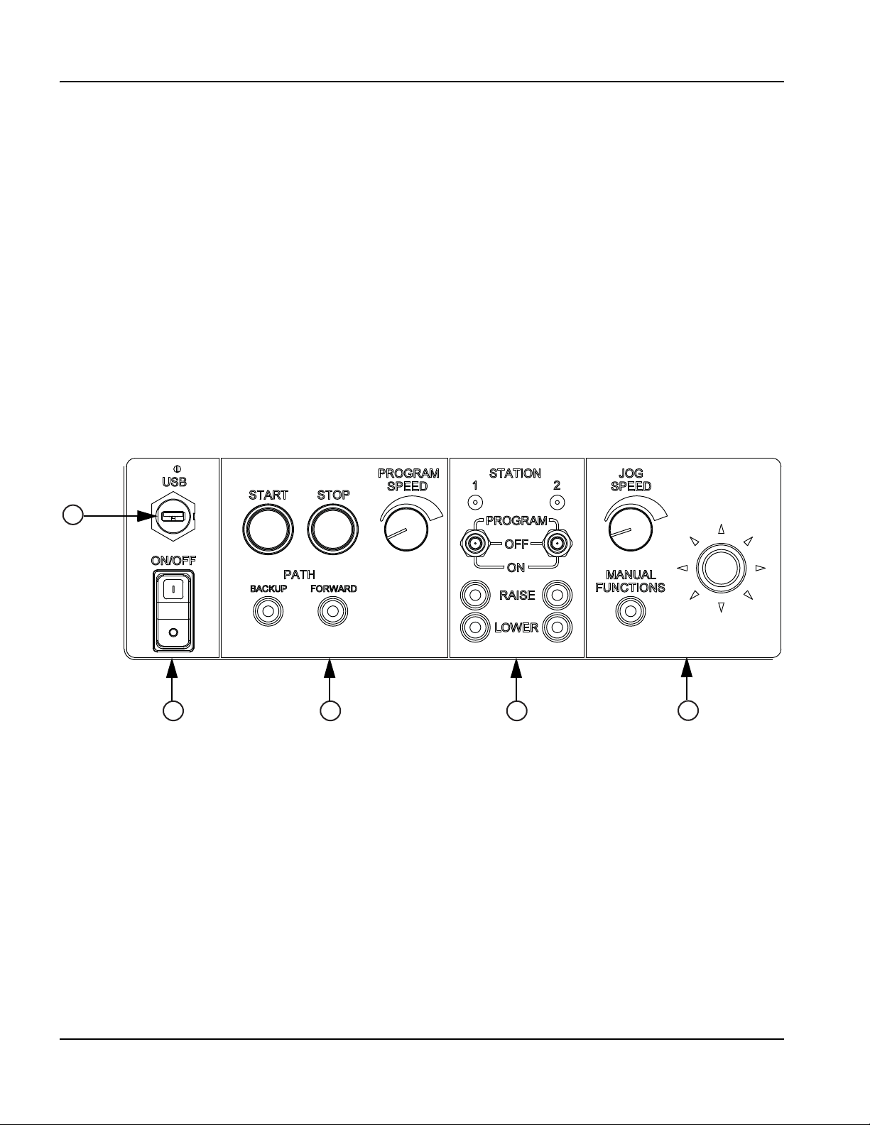
1 – Specifications
5
4
3
2
1
1
Data transfer
2
Power switch
3
Program execution controls
4
Station controls
5
Manual motion controls
Features of the EDGE Pro Picopath CNC
Features of the EDGE Pro Picopath CNC
Touchscreen
The touchscreen is a 15-inch LCD monitor combined with software that allows direct user input from the screen. A user
makes selections on the screen using check boxes, radio buttons, drop-down menus, and data input. Data input boxes
automatically display a numeric or alphanumeric keypad for entries in the fields.
The touchscreen has a resolution of 1024 x 768, or higher.
See Care and handling of the touchscreen on page 67 for more information about how to care for the touchscreen.
Operator console
The operator console provides the physical controls that allow you to regulate part program execution, as well as station
and manual motion.
Figure 4 EDGE Pro Picopath operator console
32 EDGE Pro Picopath CNC Instruction Manual 807630
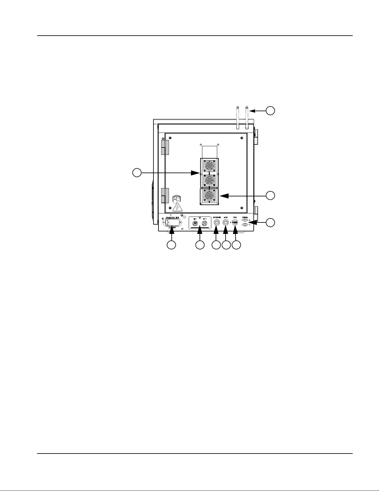
1 – Specifications
1
Drive/encoder connectors
2
Wireless antennas
3
I/O connectors
4
Serial ports
5
USB port
6
LAN port
7
Hypernet port
8
Optional Sensor THC interfaces (2)
9
AC power input
74985
6
3
2
1
Features of the EDGE Pro Picopath CNC
Rear panel
The rear panel of the EDGE Pro Picopath CNC has cable connectors for power, motion control, I/O, and communication
ports. These connectors are clearly labeled with their function. In addition, there are two antennas for wireless LAN
communication.
Figure 5 Rear panel of a 4-axis, 12-I/O EDGE Pro Picopath CNC
EDGE Pro Picopath CNC Instruction Manual 807630 33

1 – Specifications
System specifications
System specifications
The following table contains technical specifications for the EDGE Pro CNC.
Table 1 System specifications for the EDGE Pro CNC
System features
Processor
Operating system Windows XPe
RAM
LAN port 1 RJ-45 Ethernet port
Hypernet port 1 Hypernet port for use with the ArcGlide THC and Hypertherm Fiber Laser systems
USB ports 2 USB 2.0 ports
Serial ports 2 RS-422/RS-232 configurable ports with D-sub 9-pin connectors
Wireless communication Complies with 802.11G and 802.11N standards.
Onboard monitoring devices Hardware monitoring, CPU fan, CPU temperature, voltages, POST display
Hard drive SATA drive
Operator console 2-station standard (can be expanded by table manufacturer)
Display 381 mm (15 in.) touchscreen, surface acoustic wave glass
Regulatory compliance CE, CSA, GOST-TR, C-Tick, UkrSEPRO
Configuration
Number of I/O 12/12
I/O Type Negative logic, input and output
Axes available 2 – 4
Intel® Processor
1GB
Power
AC input Voltage: 100 VAC to 240 VAC
Current: 1.85 A at 100 VAC/0.65 A at 240 VAC
Frequency: 50/60 Hz
Slow blow fuse 250 V, 2 A, 5 mm x 20 mm (2) or 0.25 in. x 1.25 in. (1)
DC available 24 V at 1.5 A for table and I/O
34 EDGE Pro Picopath CNC Instruction Manual 807630

System features
Environmental
Temperature -10º C to 40º C (14º F to 104º F)
Humidity 95% maximum relative humidity
Ingress Protection IP21S
Protect the equipment from exposure to excessive moisture.
Altitude Operational up to 2000 m (6561 ft)
Environment Pollution degree Level II
Mechanical
Height 490.9 mm (19.33 in.)
Width 435 mm (17.13 in.)
Depth 316 mm (12.43 in.)
Weight 23.64 kg (52 lb)
1 – Specifications
System specifications
EDGE Pro Picopath CNC Instruction Manual 807630 35
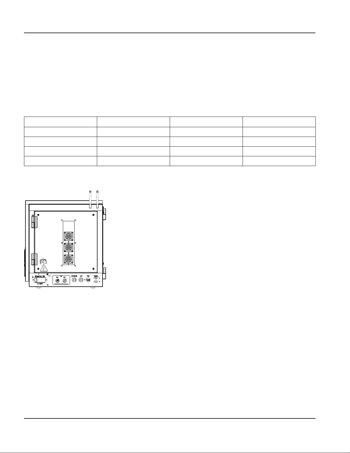
1 – Specifications
System specifications
Picopath models
The EDGE Pro Picopath CNC is available in several configurations. The basic model offers 2 to 4 axes of motion control
with 12 inputs and 12 outputs. This model is often used to retrofit an existing system that is already equipped with the
Picopath interface.
The Picopath interface can be configured to supply encoder power at 5 VDC, 12 VDC, or to use externally supplied
(stand alone) voltage encoders. See Picopath I/O circuit examples on page 52.
Table 2 EDGE Pro Picopath part numbers
Part number Number of axes Number of I/O Integrated Sensor THC
090046 2 12/12 Not available
090047 3 12/12 Not available
090048 4 12/12 Not available
090049 4 12/12 2
Figure 6 Rear panel of 090049
36 EDGE Pro Picopath CNC Instruction Manual 807630
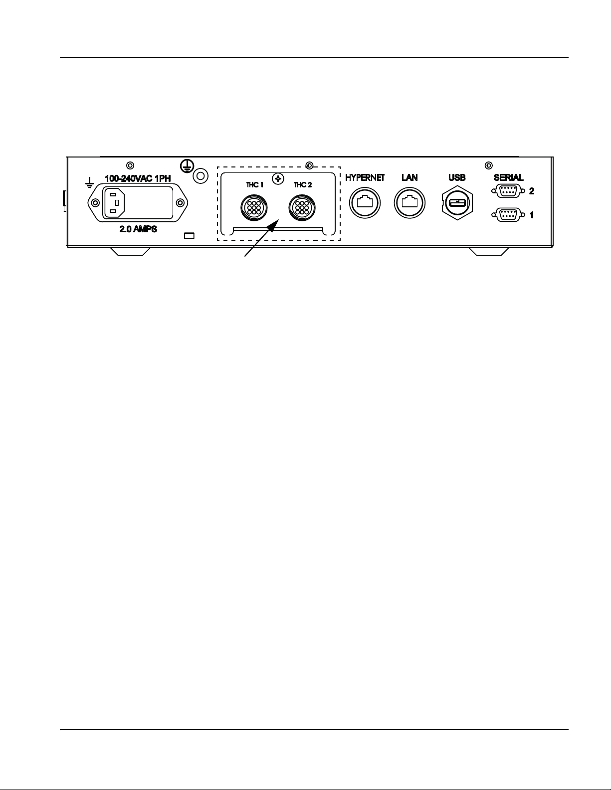
1 – Specifications
Connectors for the integrated Sensor THC
System specifications
Integrated Sensor THC
If your EDGE Pro configuration includes one or two optional integrated Sensor THCs, the CNC includes an analog input
for each THC. For more information, see Installation on page 39.
Figure 7 Interface for the integrated Sensor THC
EDGE Pro Picopath CNC Instruction Manual 807630 37
1 – Specifications
s
Symbols and Marks
Symbols and Marks
Your product may have one or more of the following markings on or near the data plate. Due to differences and conflicts
in national regulations, not all marks are applied to every version of a product.
S mark
The S mark indicates that the power supply and torch are suitable for operations carried out in environments
with increased hazard of electrical shock according to IEC 60974-1.
CSA mark
Products with a CSA mark meet the United States and Canadian regulations for product safety. The products
were evaluated, tested, and certified by CSA-International. Alternatively, the product may have a mark by one
of the other Nationally Recognized Testing Laboratories (NRTL) accredited in both the United States and
Canada, such as UL or TÜV.
CE mark
The CE marking signifies the manufacturer’s declaration of conformity to applicable European directives and
standards. Only those versions of products with a CE marking located on or near the data plate have been
tested for compliance with the European Low Voltage Directive and the European Electromagnetic
Compatibility (EMC) Directive. EMC filters needed to comply with the European EMC Directive are
incorporated within versions of the product with a CE marking.
Eurasian Customs Union (CU) mark
CE versions of products that include an EAC mark of conformity meet the product safety and EMC
requirements for export to Russia, Belarus, and Kazakhstan.
GOST-TR mark
CE versions of products that include a GOST-TR mark of conformity meet the product safety and EMC
requirements for export to the Russian Federation.
C-Tick mark
CE versions of products with a C-Tick mark comply with the EMC regulations required for sale in Australia
and New Zealand.
CCC mark
The China Compulsory Certification (CCC) mark indicates that the product has been tested and found
compliant with product safety regulations required for sale in China.
UkrSEPRO mark
The CE versions of products that include a UkrSEPRO mark of conformity meet the product safety and EMC
requirements for export to the Ukraine.
Serbian AAA mark
CE versions of products that include a AAA Serbian mark meet the product safety and EMC requirements for
export to Serbia.
38 EDGE Pro Picopath CNC Instruction Manual 807630

Section 2
Installation
Upon receipt
• Verify that all the system components on your order have been received. Contact your supplier if any items are
missing.
•EDGEPro Picopath CNC
• Power cable (North America) (108884)
• Power connector (all other regions) (108842)
• EDGE Pro Picopath CNC instruction manual (807630)
• Phoenix software instruction manuals (806400, 806410, 806420)
• Any other optional components that appear on your order form
• Inspect the system components for any physical damage that may have occurred during shipping. If there is evidence
of damage, refer to the following topic, Claims on page 39. All communications regarding claims must include the
model number and serial number located on the back of the CNC.
• Record your product information on the inside front cover of this manual, then use the instructions there to register
your product’s serial number at www.hypertherm.com.
Claims
Claims for damage during shipment – If your unit was damaged during shipment, you must file a claim with the carrier.
Hypertherm will furnish you with a copy of the bill of lading upon request. If you need additional assistance, call Customer
Service listed in the front of this manual, or your authorized Hypertherm distributor.
Claims for defective or missing merchandise – If any of the merchandise is defective or missing, contact your supplier.
If you need additional assistance, call Customer Service listed in the front of this manual, or your authorized Hypertherm
distributor.
Installation requirements
All installation and service of electrical systems must conform to national and local electrical codes. This work should be
performed only by qualified personnel.
EDGE Pro Picopath CNC Instruction Manual 807630 39
2 – Installation
Mounting the CNC
Placement of system components
• Place all system components in position prior to making electrical, gas and interface connections. See Mounting the
CNC on page 40 for details.
• Ground all system components to earth. See Recommended grounding and shielding practices on page 43 for
grounding details.
WARNING!
Use a 2-man lift to position the EDGE Pro Picopath CNC and avoid bodily injury.
Mounting the CNC
Before you connect the EDGE Pro Picopath CNC to other system components, mount all the components using the
appropriate instructions.
Do not allow the system components to lie unsecured on top of cabinets or on the floor.
40 EDGE Pro Picopath CNC Instruction Manual 807630
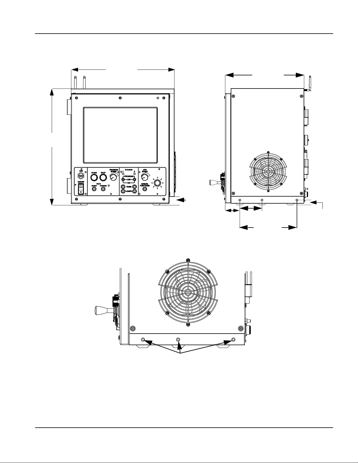
Enclosure dimensions
36 mm
(1.42 in)
435 mm
(17.13 in)
316 mm
(12.43 in)
21 mm
(0.82 in)
228.5 mm
(9.00 in)
90 mm
(3.50 in)
58 mm
(2.29 in)
Use M6 x 1 hardware for side mounting.
Maximum length inside enclosure must not exceed 7.8 mm (0.31 in.)
491 mm
(19.33 in)
Figure 8 Front and side views of the Picopath CNC
2–Installation
Mounting the CNC
EDGE Pro Picopath CNC Instruction Manual 807630 41

2 – Installation
Use M6 x 1 hardware.
(10 places)
Maximum length inside
enclosure must not
exceed 7.8 mm (0.31 in.)
305 mm
(12 in)
356 mm
(14 in)
58 mm
(2.29 in)
94 mm
(3.7 in)
203 mm
(8 in)
127 mm
(5 in)
109.2 mm
(4.3 in)
148 mm
(5.8 in)
89 mm
(3.5 in)
Mounting the CNC
Mounting hole patterns on the bottom of the CNC
The EDGE Pro Picopath CNC has 10 mounting holes on the bottom of the enclosure for mounting the CNC to the
cutting table. Fasten the mounting screws through the holes that will provide the most stability for your CNC during the
operation of your table.
Figure 9 EDGE Pro Picopath CNC mounting hole pattern
42 EDGE Pro Picopath CNC Instruction Manual 807630

2–Installation
Mounting the CNC
Recommended grounding and shielding practices
WARNING!
ELECTRIC SHOCK CAN KILL
Disconnect electrical power before performing any maintenance.
All work requiring the removal of the plasma system cover must be performed
by a qualified technician.
See the Safety section of your manual for more safety precautions.
Introduction
This section describes practices for grounding and shielding to protect a plasma cutting system against radio frequency
interference (RFI) and electromagnetic interference (EMI) (also called noise). It also describes the DC power ground and
the service ground. The diagram at the end of this section shows these types of grounds in a plasma cutting system.
The grounding practices in this section have been used on many installations with excellent results, and Hypertherm
recommends that these practices be a routine part of the installation process. The actual methods used to implement
these practices may vary from system to system, but should remain as consistent as possible. However, due to the
variation in equipment and installations, these grounding practices may not succeed in every case to eliminate RFI/EMI
noise issues.
Types of grounding
Service ground (also called safety ground or potential earth (PE) ground) is the grounding system that applies to the
incoming line voltage. It prevents a shock hazard to any personnel from any of the equipment or the cutting table. It
includes the service ground coming into the plasma system and other systems such as the CNC and the motor drives, as
well as the supplemental ground rod connected to the cutting table. In the plasma circuits, the ground is carried from the
plasma system chassis to the chassis of each separate console through the interconnecting cables.
DC power ground (also called cutting current ground) is the grounding system that completes the path of the cutting
current from the torch back to the plasma system. It requires that the positive lead from the plasma system be firmly
connected to the cutting table ground bus with a properly sized cable. It also requires that the slats, on which the
workpiece rests, make firm contact with the table and the workpiece.
RFI and EMI grounding and shielding is the grounding system that limits the amount of electrical noise emitted by
the plasma and motor drive systems. It also limits the amount of noise that is received by the CNC and other control and
measurement circuits. The grounding practices described in this section mainly target RFI and EMI grounding and
shielding.
Grounding practices
1. Unless noted, use only 13.3 mm2 (6 AWG) welding cables (047040) for the EMI ground cables shown on the
diagram at the end of this section.
2. The cutting table is used for the common, or star, EMI ground point and should have threaded studs welded to the
table with a copper bus bar mounted on them. A separate bus bar should be mounted on the gantry as close to
EDGE Pro Picopath CNC Instruction Manual 807630 43

2 – Installation
Mounting the CNC
each motor as possible. If there are motors at each end of the gantry, run a separate EMI ground cable from the
2
far motor to the gantry bus bar. The gantry bus bar should have a separate, heavy EMI ground cable 21.2 mm
(4 AWG; 047031) to the table bus bar. The EMI ground cables for the torch lifter and the RHF console must each
run separately to the table ground bus.
3. A ground rod that meets all applicable local and national electrical codes must be installed within 6 m (20 ft) of the
2
cutting table. This is a PE ground and should be connected to the cutting table ground bus bar using 13.3 mm
(6 AWG) green and yellow grounding cable (047121) or equivalent.
4. For the most effective shielding, use the Hypertherm CNC interface cables for I/O signals, serial communication
signals, between plasma systems in multi-drop connections, and for interconnections between all parts of the
Hypertherm system.
5. All hardware used in the ground system must be brass or copper. While you can use steel studs welded to the
cutting table for mounting the ground bus, no other aluminum or steel hardware can be used in the ground system.
6. AC power, PE, and service grounds must be connected to all equipment according to local and national codes.
7. For a system with a remote high frequency console (RHF), the positive, negative, and pilot arc leads should be
bundled together for as long a distance as possible. The torch lead, work lead, and the pilot arc (nozzle) leads may be
run parallel to other wires or cables only if they are separated by at least 150 mm (6 inches). If possible, run power
and signal cables in separate cable tracks.
8. For a system with an RHF console, the ignition console should be mounted as closely as possible to the torch, and
must have a separate ground cable that connects directly to the cutting table ground bus bar.
9. Each Hypertherm component, as well as any other CNC or motor drive cabinet or enclosure, must have a separate
ground cable to the common (star) ground on the table. This includes the ignition console, whether it is bolted to the
plasma system or to the cutting table.
10. The metal braided shield on the torch lead must be connected firmly to the ignition console and to the torch. It must
be electrically insulated from any metal and from any contact with the floor or building. The torch lead can be run in a
plastic cable tray or track, or covered with a plastic or leather sheath.
11 . The torch holder and the torch breakaway mechanism – the part mounted to the lifter, not the part mounted to the
torch – must be connected to the stationary part of the lifter with copper braid at least 12.7 mm (0.5 inches) wide. A
separate cable must run from the lifter to the gantry ground bus bar. The valve assembly should also have a separate
ground connection to the gantry ground bus bar.
12. If the gantry runs on rails that are not welded to the table, then each rail must be connected with a ground cable from
the end of the rail to the table. The rail ground cables connect directly to the table and do not need to connect to the
table ground bus bar.
13. If you are installing a voltage divider board, mount it as closely as possible to where the arc voltage is sampled.
One recommended location is inside the plasma system enclosure. If a Hypertherm voltage divider board is used, the
output signal is isolated from all other circuits. The processed signal should be run in twisted shielded cable
(Belden 1800F or equivalent). Use a cable with a braided shield, not a foil shield. Connect the shield to the chassis
of the plasma system and leave it unconnected at the other end.
14. All other signals (analog, digital, serial, and encoder) should run in twisted pairs inside a shielded cable. Connectors
on these cables should have a metal housing. The shield, not the drain, should be connected to the metal housing of
the connector at each end of the cable. Never run the shield or the drain through the connector on any of the pins.
44 EDGE Pro Picopath CNC Instruction Manual 807630

2–Installation
1 Gantry ground bus
2 Ground rod
3 Plasma system lead (+)
4 Remote high frequency (RHF) console
5 CNC enclosure
6 Torch holder
7 Plasma system chassis
1 2 3
4
5 6 7
1 Cable to the cutting table ground bus
2 Ground cables from components on the gantry
1 2
Mounting the CNC
The following picture shows an example of a cutting table ground bus. The components shown here may differ from your
system.
The following picture shows an example of a gantry ground bus. It is bolted to the gantry, close to the motor. All of the
individual ground cables from the components mounted on the gantry connect to the bus. A single heavy cable then
connects the gantry ground bus to the table ground bus.
EDGE Pro Picopath CNC Instruction Manual 807630 45

2 – Installation
Chassis and RFI ground
AC earth ground
1
2
3
4
5
6
7
8 9
10
11
12
13
1 Cutting table
2 Gantry
3 Plasma system
4 Table ground bus bar
5 Gantry ground bus bar
6 Torch height control lifter (ArcGlide, Sensor THC,
Sensor PHC, or other)
7 RHF console (not on all systems). Connect to table
ground bus bar.
8, 9 System-specific component such as metering
console, gas console, or selection console
10 CNC chassis
11 Torch height control module
(ArcGlide, Command THC)
12 System-specific component such as a cooler or
chiller
13 DC power ground
Mounting the CNC
Grounding diagram
The following diagram shows an example of grounding the components in a plasma cutting system.
46 EDGE Pro Picopath CNC Instruction Manual 807630

2–Installation
X-
Y-
Y+
X+
1
EDGE Pro Picopath CNC
2
CNC operator console
3
Table origin and Home position (0,0)
3
2
X and Y axis configuration
X and Y axis configuration
To configure the X and Y axes, first decide which axis on the table will be the X axis and where the home position will be.
Next, define the X and Y orientation and home position in Phoenix software (Setups > Password > Machine Setups) to
match the configuration you want on the table. The definition of the axes orientation and home position in software and on
the table must agree so the system can execute the part programs as expected.
Figure 10 Example of a shape cutting system configured with an EDGE Pro Picopath CNC
1
EDGE Pro Picopath CNC Instruction Manual 807630 47

2 – Installation
The operator console
The operator console
The EDGE Pro Picopath CNC comes with a 2-station operator console that allows you to operate two cutting torches or
stations.
The operator console allows you to:
• Start and stop the cutting program
• Switch to manual mode
• Manually jog the torch with the joystick
• Jog forward or backward on path
• Adjust the jog and cutting feed rates
• Activate or deactivate the 2 cutting stations
The device I/O for the operator console are assigned to Input and Output 129 and higher, as listed in Table 3.
Operator console and dedicated I/O
The I/O for the devices on the operator console of the CNC are all pre-assigned as factory defaults. These I/O
assignments begin at 129.
Table 3 Operator console and dedicated I/O assignments
Function Input No. Output No.
Front Panel Start 129
Front Panel Stop 130
Front Panel Manual 131
Front Panel Forward On Path 132
Front Panel Backward On Path 133
Jog Up 134
Jog Down 135
Jog Left 136
Jog Right 137
Auto Select 1 138
Manual Select 1 139
Raise Torch 1 140
Lower Torch 1 141
Auto Select 2 142
Manual Select 2 143
Raise Torch 2 144
Lower Torch 2 145
Station Enable LED 1 129
Station Enable LED 2 130
Speed Pot 1 (Program Speed) Analog Input 1
Speed Pot 2 (Jog Speed) Analog Input 2
Scaled interior temperature Analog Input 4
Note: If you load a setup file from a different Hypertherm CNC, these I/O assignments will not change.
Phoenix software restores these assignments the next time it starts up.
48 EDGE Pro Picopath CNC Instruction Manual 807630
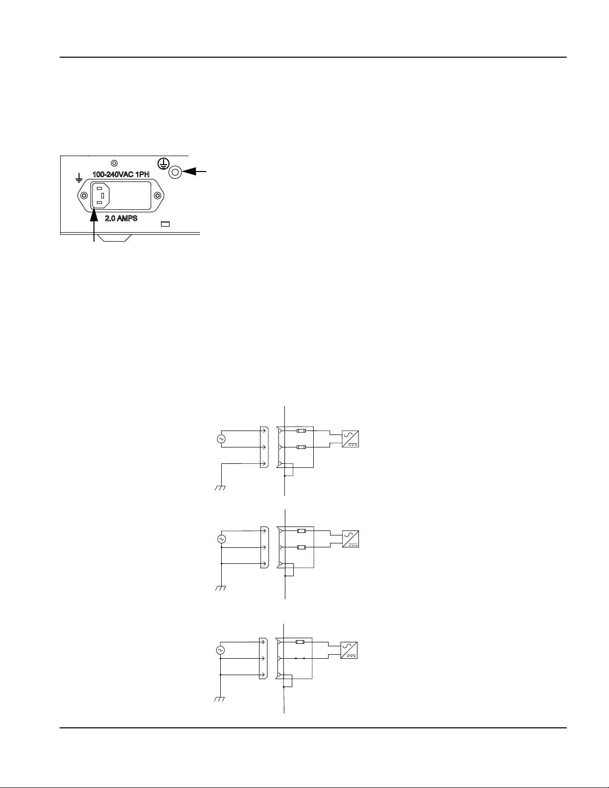
2–Installation
AC Power connector
Voltage range: 115 to 240 V, single phase
Fuse size: 250 V, 2 Amp, slow-blow,
5 mm x 20 mm (2) or 0.25 in. x 1.25 in. (1)
Ground nut and lock washer 1/4 in. – 20 UNC
EDGE Pro Picopath CNC (as shipped)
Power entry module:
2 Fuses: 250 V, 2A, slow blow, 5 mm x 20 mm
EDGE Pro Picopath CNC (as shipped)
Power entry module:
2 Fuses: 250 V, 2 A, slow blow, 5 mm x 20 mm
Customer-supplied power
L1 – line
L2 – line
PE ground
L1 – line
L2 – neutral
PE ground
Customer-supplied power
EDGE Pro Picopath CNC
(field selectable option)
Power entry module:
1 Fuse: 250 V, 2 A, slow blow, 0.25 in. x 1.25 in.
L1 – line
L2 – line
PE ground
Customer-supplied power
AC power
AC power
Power input
Figure 11 AC power input connector illustrates the power input connector on the rear of the EDGE Pro Picopath CNC.
Figure 11 AC power input connector
An AC power cable is standard equipment for North America, and is shipped with the CNC. For other regions, use a
power cable that has an IEC-60320-C13 end which meets the requirements of local code and power connections.
To create a power cable, use the power connector (108842) that ships with the CNC and connect a 3-wire cable for line,
neutral, and ground signals according to local electrical codes. For more electrical specifications, see System
specifications on page 34. Figure 12 shows examples of how power cables can be created.
Figure 12 Input VAC wiring examples
EDGE Pro Picopath CNC Instruction Manual 807630 49
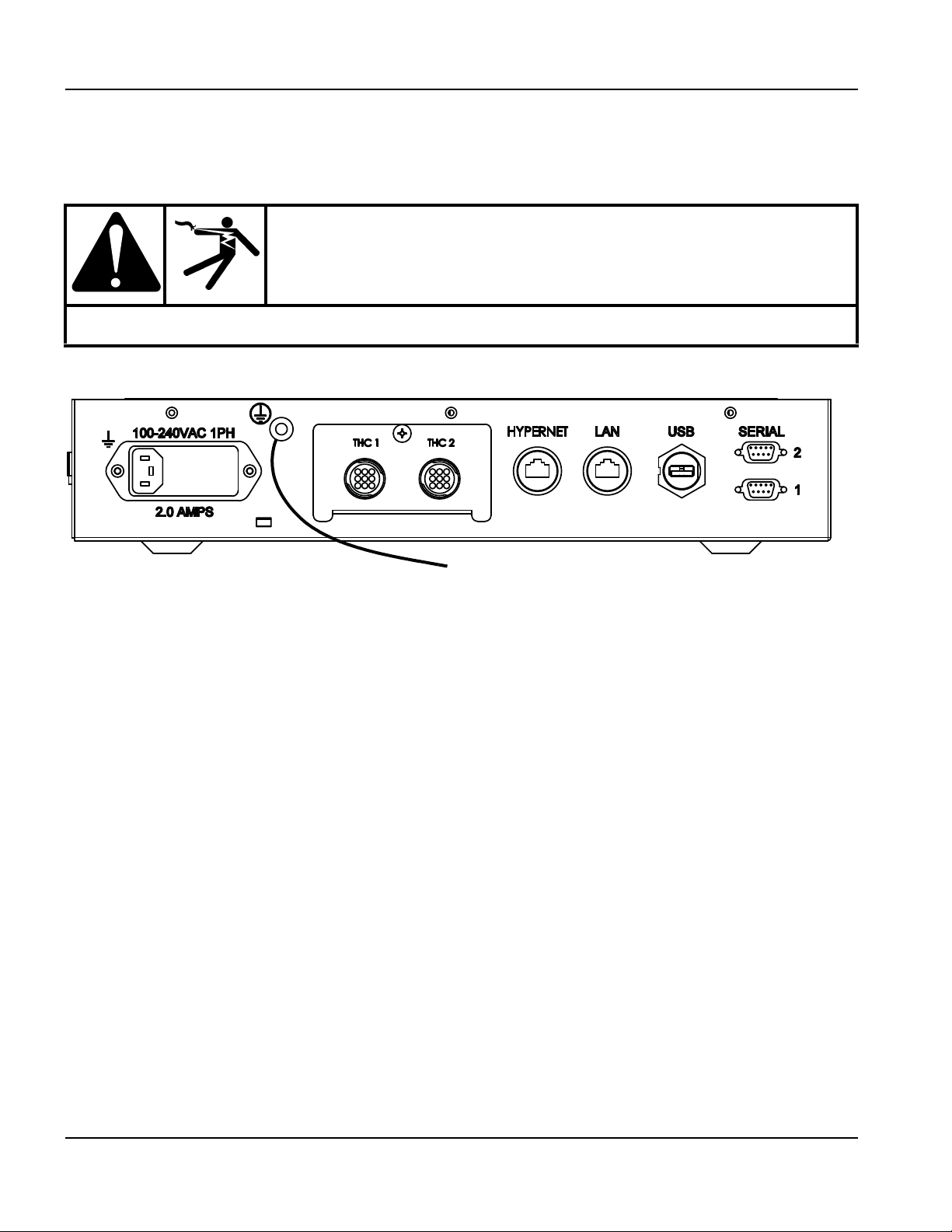
2 – Installation
To the star ground on the cutting table.
The ground stud has a 1/4-20 thread.
AC power
Chassis grounding
The CNC must be properly grounded according to national and local electrical codes for safe operation. Use a number
2
16 mm
shown in Figure 13.
(6 AWG) wire between the ground stud on the rear of the CNC and the star ground on the cutting table, as
WAR NING!
ELECTRIC SHOCK CAN KILL
This ground connection must be wired for safe and reliable operation.
Figure 13 Ground cable on the CNC
50 EDGE Pro Picopath CNC Instruction Manual 807630

2–Installation
Communication interfaces
Communication interfaces
Figure 14 illustrates the interface ports and their location on the rear of the EDGE Pro Picopath CNC.
Figure 14 Interface ports
Hypernet interface
The Hypernet interface allows the EDGE Pro Picopath CNC to connect to an ArcGlide THC and plasma system using
the Hypernet protocol over shielded, Ethernet Cat-5e cables. This configuration must include an industrial-grade
Ethernet switch to route communication from the EDGE Pro Picopath
List for Hypernet cable lengths and part numbers.
LAN interface
CNC to the other units in the system. See Parts
The RJ-45 LAN interface allows the EDGE Pro Picopath CNC to connect to a local area network (LAN) for downloading
parts and using Remote Help. See Parts List for LAN cable lengths and part numbers.
For more information on setting up the CNC to communicate over a LAN, see the Phoenix Software V9 Series
Installation and Setup Manual (806410).
USB interface
The USB 2.0 port on the back of the EDGE Pro Picopath CNC, like the one on the operator console, can be used to load
programs or to connect a USB keyboard or mouse.
Serial ports
The two serial RS-232/RS-422 ports on the back of the EDGE Pro Picopath CNC are configurable ports and accept
D-sub 9-pin connectors. Transmission rate is up to 115K Baud. Both ports are preset for RS-422 as the default. For
more information, see Utility and serial isolation board on page 103.
Wireless antennas
The wireless antennas on the back of the EDGE Pro Picopath CNC are connected to the wireless network board
(141223). The wireless board conforms to 802.11N and 802.11G standards and connects to either a wireless G or N
LAN. It provides wireless G or better performance for part program downloads, Remote Help, or other network tasks.
For information about connecting your CNC to a wireless network, see Networking in the Phoenix Software V9 Series
Installation and Setup Manual (806410).
EDGE Pro Picopath CNC Instruction Manual 807630 51
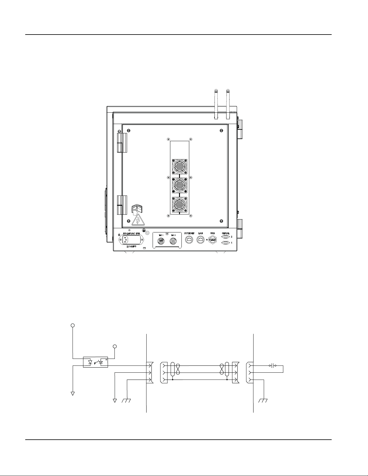
2 – Installation
CNC
+5 VDC
+24 VDC
Customer-supplied cable
Common
Shield
37
Customer circuit
Switch (normally open)
Picopath I/O
Picopath I/O
I/O assignments are made in the Phoenix software on the I/O Setup screen. For more information, see the Phoenix
Software V9 Series Installation and Setup Manual (806410).
Figure 15 Rear view of the EDGE Pro CNC with Picopath I/O configuration
Picopath I/O offers:
• 12 inputs rated at 24 VDC
• 12 outputs, rated at 24 VDC for up to 1-amp loads
• 24 VDC field power supply on the Picopath PCB with a total usage of 1.5 A
Picopath I/O circuit examples
Figure 16 Input – CNC sinking
52 EDGE Pro Picopath CNC Instruction Manual 807630
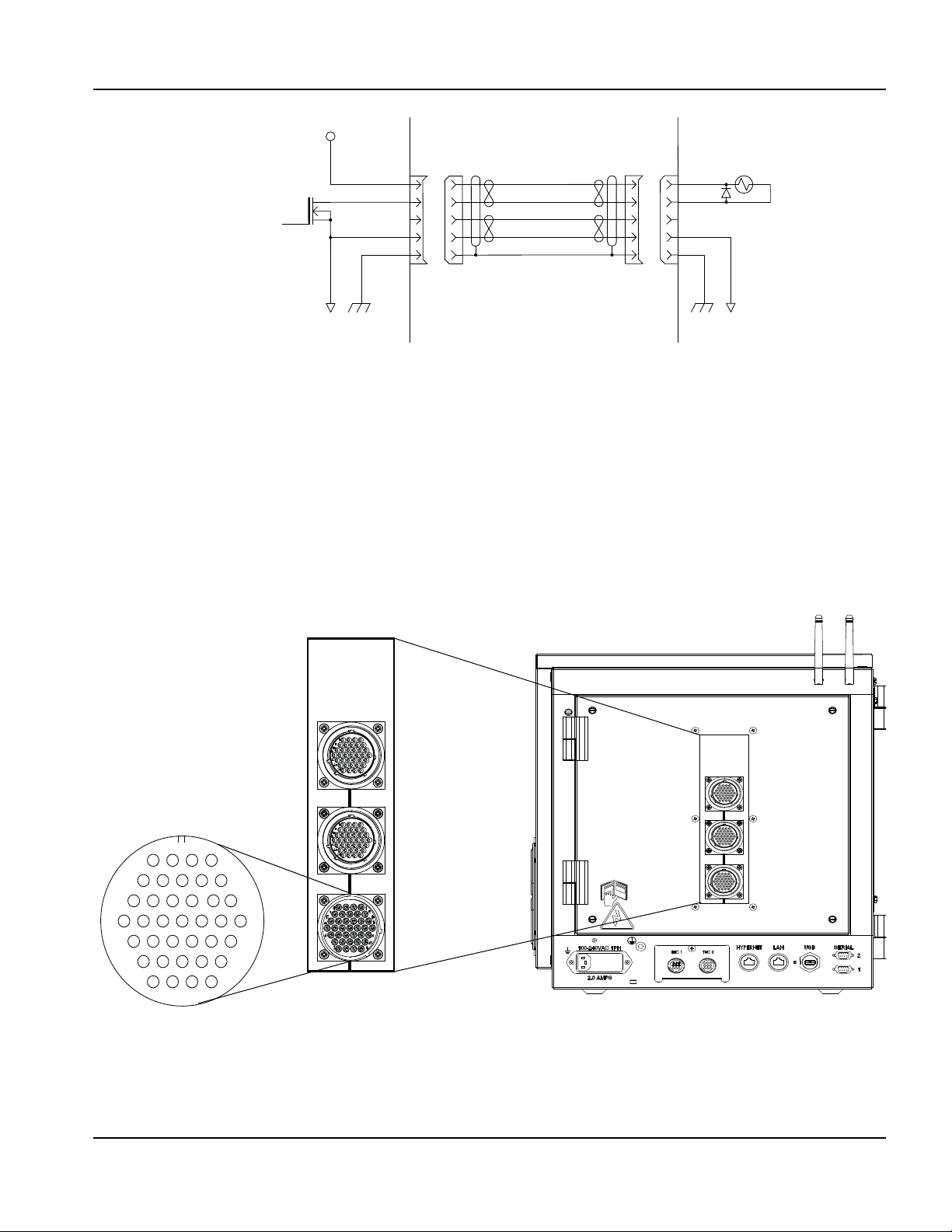
2–Installation
Customer circuit
24 VDC coil with diode
FET
CNC Customer-supplied cable
Shield
Common
+24 VDC
37
1
5
10
16
23
29
34
4
9
15
22
28
33
37
Z (3)/W (4) axis
drive encoder
X (1)/Y (2) axis
drive encoder
J8 12 I/O
Picopath I/O
Figure 17 Output, 24 VDC coil – CNC sinking
Picopath I/O connection
This section describes the Picopath I/O cables, connectors, and the I/O signals that are transmitted across them.
Picopath I/O cables
Use the following information to create Picopath I/O cables.The Picopath I/O mating connector is a male circular
connector.
• Hypertherm kit: 228490
• Cable connector: AMP 208470-1
• Cable clamp: AMP 208945-8
• Socket contacts (37): AMP 66105-3 (20 – 24 AWG)
Figure 18 Picopath I/O Connector J8
EDGE Pro Picopath CNC Instruction Manual 807630 53

2 – Installation
Picopath I/O
Picopath pinouts for 12 I/O
Picopath 12 I/O
Pin no. Signal Pin no. Signal Pin no. Signal
1
2
3
4
5
6
7
8
9
10
11
12
Input 1
Input 2
Input 3
Input 4
Input 5
Input 6
Input 7
Input 8
Input 9
Input 10
Input 11
Input 12
13
14
15
16
17
18
19
20
21
22
23
24
N/C
+24 VDC
+24 VDC
N/C
24 V Common
24 V Common
N/C
N/C
Output 1
Output 2
Output 3
Output 4
25
26
27
28
29
30
31
32
33
34
35
36
37
Output 5
Output 6
Output 7
Output 8
Output 9
Output 10
Output 11
Output 12
I/O Shield
+24 VDC
+24 VDC
24 V Common
24 V Common
54 EDGE Pro Picopath CNC Instruction Manual 807630

2–Installation
Picopath drive/encoder connection
Picopath drive/encoder connection
Picopath axis assignments are made in Phoenix software, on the Axis Setup screen. For more information, see the
Phoenix Software V9 Series Installation and Setup Manual (806410).
Picopath drive/encoder cable
The Picopath drive/encoder mating connector is a 37-pin female circular connector.
Use the following information to create Picopath drive/encoder cables.
• Hypertherm kit: 228489
• Cable connector: AMP 208472-1
• Cable clamp: AMP 208945-8
• Pin contacts (37): AMP 66103-3 (20 – 24 AWG)
• Cabling: Belden 9504 or equivalent for encoder signals
• Cabling: Belden 9501 or equivalent for drive signals
Note: Tie cable shields to the metal shell of the connector for optimum noise immunity and to separate signal
commons from the ground.
EDGE Pro Picopath CNC Instruction Manual 807630 55
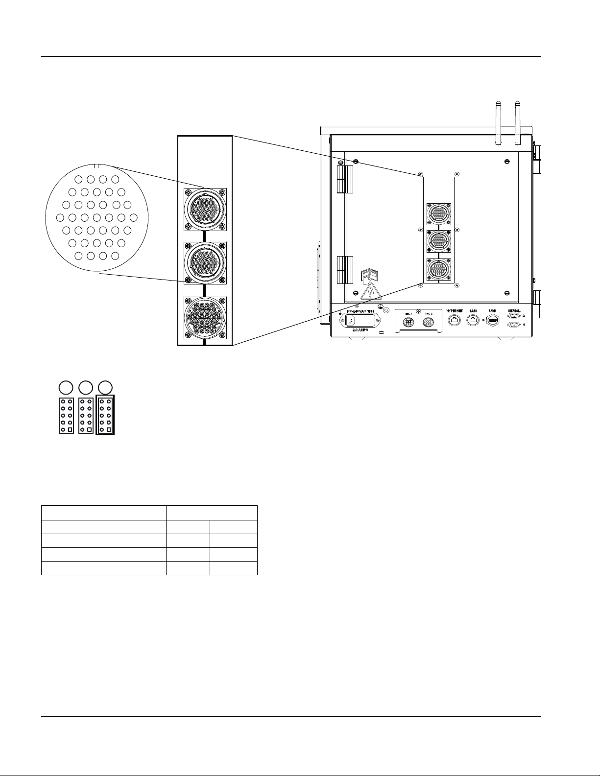
2 – Installation
1
5
10
16
23
29
34
4
9
15
22
28
33
37
J6
Z (3)/W (4) axis
drive encoder
J7
X (1)/Y (2) axis drive
encoder
Jumpers on the servo board (141122 or 141254) allow you to select:
1
Customer-supplied encoder and field power
2 12 VDC sourced encoder power
3 5 VDC sourced encoder power (default)
321
Picopath drive/encoder connection
Picopath drive/encoder connector
Figure 19 Picopath drive/encoder connectors J6 and J7
Tabl e 4
Axis assignment
Transverse or Rail X 1
Rail or Transverse Y 2
Dual Gantry* or Sensor THC Z 3
Sensor THC* W 4
Axis
* If you do not have Dual Gantry, Z (3) is Sensor THC. If you have Dual Gantry, Z (3) is Dual Gantry and W (4)
is Sensor THC.
56 EDGE Pro Picopath CNC Instruction Manual 807630

2–Installation
Picopath drive/encoder connection
Picopath drive/encoder pinouts
Pinouts for connector J7 Pinouts for connector J6
Axis
X (1) Y (2) Z (3) W (4)
22
33Encoder power common 33Encoder power common
77Encoder power shield 77Encoder power shield
41
86
95Encoder Channel A input 95Encoder Channel A input
14 11 Encoder Channel /A Input 14 11 Encoder Channel /A Input
15 10 Encoder Channel B Input 15 10 Encoder Channel B Input
21 17 Encoder Channel /B Input 21 17 Encoder Channel /B Input
22 16 Encoder Channel Z Input 22 16 Encoder Channel Z Input
28 23 Encoder Channel /Z Input 28 23 Encoder Channel /Z Input
13 12 Encoder shields 13 12 Encoder Shields
24 26
25 27
37 34
33 29 Servo output (± 10 VDC) 33 29 Servo output (± 10 VDC)
32 30 Drive power common 32 30 Drive power common
36 35
20 18 Servo output common 20 18 Servo output common
19 31 Drive/servo shield 19 31 Drive/servo shield
+5 VDC or +12 VDC sourced for
encoder power
Encoder power output
(available if needed)
Encoder power common
(available if needed)
Drive Enable In
(relay contact closure)
Drive Enable Out
(relay contact closure)
Drive Power Input
(+12 VDC or +15 VDC)
Drive power input
(-12 VDC or -15 VDC)
Signal
Axis
22
41
86
24 26
25 27
37 34
36 35
+5 VDC or +12 VDC sourced for
encoder power
Encoder power output
(available if needed)
Encoder power common
(available if needed)
Drive Enable In
(relay contact closure)
Drive Enable Out
(relay contact closure)
Drive power input
(+12 VDC or +15 VDC)
Drive power input
(-12 VDC or -15 VDC)
Signal
Note: Tie cable shields to the external PE studs for optimum noise immunity.
EDGE Pro Picopath CNC Instruction Manual 807630 57

2 – Installation
Integrated THC I/O configuration
Integrated THC I/O configuration
THC I/O Interface
Figure 20 THC1 and THC 2 Interface
THC I/O pinouts
Pin no. THC 1 THC 2 Signal
1
2
3
4
5
6
7
8
9
Common Common Common
Input + Input + Nozzle contact sense +
Input - Input - Nozzle contact sense -
Output + Output + Nozzle contact enable + (relay contact)
Output - Output - Nozzle contact enable - (relay contact)
Analog Input + Analog Input + THC +
Analog Input - Analog Input - THC -
Output + Output + Hold ignition (relay contact)
Output - Output - Hold ignition (relay contact)
Ground Stud Ground Stud Shield
58 EDGE Pro Picopath CNC Instruction Manual 807630

2–Installation
Integrated THC I/O configuration
THC cables
The following list and tables provide the details for the connectors on the Sensor THC, the EDGE Pro CNC, and the
voltage divider board (VDC3) (141201). Use this information to manufacture the cables and connectors to connect these
devices in your system.
The THC cable connector is a 9-pin, male, circular connector:
• Hypertherm kit: 228495
• Cable connector: AMP 206708-1
• Cable clamp: AMP 206966-7
• Socket contacts (9): AMP 66105-3 (20 – 24 AWG)
J1 Power connector on VDC3
Pin no. Signal
1
2
Pinout for the cable between J2 on VDC3 and THC 1 or THC2 on the CNC
J2 I/O Connector on VDC3 THC1 and THC2 connector on the CNC
Pin no.
1
2
3
Nozzle contact sense (output)
4
5
6
7
8
- Analog out (analog common)
EMI chassis ground (cable shield)
120 VAC line
120 VAC neutral
Signal
24 VDC common (out)
+24 VDC (out)
Nozzle contact enable (input)
24 VDC common (out)
+ Analog out
Pin no.
1
2
3
4
5
6
7
Outputs
24 VDC common (in)
Nozzle contact sense +
Nozzle contact sense -
Nozzle contact enable +
Nozzle contact enable -
+ Analog in
- Analog in
J3 Field connector on VDC3 (black terminal strip)
Pin no. Signal
1*
2
3
4
5
EMI chassis ground
Electrode (connection to negative connection inside plasma system)
Work (connection to the positive connection inside the plasma system)
No connection
Torch t ip shiel d
* This pin is not connected under normal conditions. If you have noise problems, connect this pin to an adjacent
metal chassis.
EDGE Pro Picopath CNC Instruction Manual 807630 59

2 – Installation
Integrated THC I/O configuration
60 EDGE Pro Picopath CNC Instruction Manual 807630

Section 3
1
Data transfer
2
Power switch
3
Program execution controls
4
Station controls
5
Manual motion controls
4
5
3
2
Operation
Operating the CNC
The EDGE Pro CNC supports a touchscreen with an optional USB-connected keyboard and mouse for entering
information and navigating the software. For more information, see the Phoenix Software Operator Manual (806400).
For more information about the components of your cutting system that are supplied by your table manufacturer, refer to
the manuals supplied by the manufacturer.
An operator console powers up the CNC and controls machine motion such as station selection, raising or lowering the
cutting tool, and positioning the cutting tool before starting a part program.
Figure 21 The EDGE Pro operator console is shown below.
1
EDGE Pro Picopath CNC Instruction Manual 807630 61

3 – Operation
Operating the CNC
Touchscreen LCD
The Phoenix software is designed for touchscreens with 1024 x 768 resolution. You can enter data into the software by
touching the window controls and fields. Any field that requires data input automatically displays an on-screen keypad
when you double-tap it.
Touchscreens, drops of water, and unintended motion
Drops of water can be a safety concern if the CNC is installed on an X-Y water table and the Watch Window displays jog
keys. If water splashes from the table onto the touchscreen, the drops can activate a jog key and create unintended
motion on the table. Unintended motion can result in danger to the operator and other people, damage to machinery,
or faults in cutting. To prevent motion caused by drops of water on the touchscreen:
• Insure that your hands are dry when you use the touchscreen.
• Install the CNC so that the touchscreen is shielded from water splashes.
• If water could accidently hit the touchscreen, do not display the jog keys in the Watch Window.
For additional information, contact your local Hypertherm Technical Service team.
Screen navigation
The keys located at the bottom of the screen in the software are called soft keys. The soft keys correspond to function
keys on a PC keyboard. OK and Cancel soft keys let you save or cancel changes that you make in a screen.
For more information, refer to the Phoenix Software Operator Manual (806400).
Note: The features shown on each screen vary depending on the user level (Beginner, Intermediate, or Advanced)
and the features enabled on the Special Setups and Station Configuration screens. This manual assumes the
CNC is in Advanced Mode and shows all features.
62 EDGE Pro Picopath CNC Instruction Manual 807630

Help
Choose the Help soft key to display information about each screen
Choose the OK soft key to exit the Help screen and return to the control screen.
3–Operation
Operating the CNC
The Show Bookmarks soft key opens the navigation pane.
View additional manuals
The Help screen may also display soft keys for other types of information, for example:
• Manuals for the Hypertherm equipment installed with your CNC, such as plasma systems or torch
height controls.
• Manuals for equipment provided by your table manufacturer.
Choose any of these keys to view this additional information.
EDGE Pro Picopath CNC Instruction Manual 807630 63

3 – Operation
Automated operations
Show bookmarks
Note: Choose the Show Bookmarks soft key on the Help screen to view the list of Help topics. Click on a topic
in the list to view it.
Automated operations
The Phoenix software includes two wizards that automate workpiece alignment and part cutting operations.
Align Wizard
The Align Wizard automates several tasks including aligning a nest on a workpiece, adjusting for a skewed workpiece,
and positioning the torch at the program start location.
To start the Align Wizard, choose Current Part Options on the Main screen, then choose Align. The Align Wizard may
launch automatically. If not, choose the Align Wizard soft key.
For more information, see Align Wizard in the Phoenix Software V9 Series Operator Manual (806400).
64 EDGE Pro Picopath CNC Instruction Manual 807630

3–Operation
Updating Phoenix software
CutPro Wizard
The CutPro Wizard automates common cutting tasks including loading a part or nest, selecting the cutting process,
aligning the part or nest on the workpiece, and starting the program.
The CutPro Wizard may launch automatically when you start the CNC. If not, choose the CutPro Wizard soft key on the
Main screen to start the wizard. For more information on the CutPro Wizard see Cutting Parts in the Phoenix Software V9
Series Operator Manual (806400).
Updating Phoenix software
Hypertherm provides regular updates to the Phoenix software. You can download the most current software from the
website www.hypertherm.com. Choose Products > Automated cutting > Controls > Phoenix software updates to open
the Phoenix Software Update downloads page. On this page you can download:
• Phoenix software update (update.exe)
• Phoenix Help file (Help.exe)
• Cut charts (CutChart.exe)
To download the updates in your language, follow the instructions in the Release Notes document on the Phoenix
Software Update downloads page.
Before you update the Phoenix software, follow these guidelines:
• Back up your system files: On the Main screen, choose Files > Save to Disk > Save System Files to
Disk. See Saving System Files in Diagnostics and Troubleshooting in the Phoenix Software Operator
Manual (806400) for more information.
• Copy the files that you download from Hypertherm.com to the root folder of a USB memory stick.
The CNC cannot read files inside folders.
• Be prepared to restart the CNC after you have updated the software.
Updating the software
1. At the CNC, plug the memory stick that contains the file update.exe into a USB port.
Note: Verify that update.exe resides in the root folder of the memory stick.
2. On the Main screen, choose Setups > Password. Double-tap the screen to display an on-screen keyboard.
3. Enter UPDATESOFTWARE (all upper case, one word) and choose Enter. The Phoenix software automatically reads
the memory stick and installs the new software.
Updating the Help
1. At the CNC, plug the memory stick that contains the file Help.exe into a USB port.
Note: Verify that Help.exe resides in the root folder of the memory stick.
2. On the Main screen, choose Setups >Password. Double-tap the screen to display an on-screen keyboard.
3. Enter UPDATEHELP (all upper case, one word) and choose Enter. The Phoenix software automatically reads the
memory stick and installs the new help file.
Updating the cut charts
Hypertherm provides cut charts in two different file types: .fac and .usr. The .fac files are the factory-default cut charts.
These cut charts cannot be changed. The .usr cut charts contain any changes you have made to a cut chart and saved
with the Save Process soft key.
The cut chart update file (CutChart.exe) contains both .fac and .usr cut chart files. The update automatically overwrites all
.usr cut charts. Before installing the update, back up your modified cut charts.
EDGE Pro Picopath CNC Instruction Manual 807630 65

3 – Operation
Updating Phoenix software
Hypertherm recommends saving modified cut charts as custom cut charts. When you create a custom cut chart, Phoenix
creates a .usr file with a unique name. This prevents the custom cut charts from being overwritten by the .usr files in
CutChart.exe. See the Phoenix Software Operator Manual (806400) for instructions.
To back up modified cut charts:
1. At the CNC, insert a memory stick into a USB port.
2. On the Main screen, choose one of the cut chart soft keys, such as Plasma 1 Cut Chart.
3. Choose the Save Cut Charts soft key. Phoenix copies all the cut charts associated with the Plasma 1 Power Supply
Type onto the memory stick.
To update the cut charts:
1. At the CNC, plug the memory stick that contains the file CutChart.exe into a USB port.
Note: Verify that CutChart.exe resides in the root of the memory stick. The CNC cannot read files inside folders.
2. On the Main screen, choose Process, and choose one of the cut chart soft keys such as Plasma 1 Cut Chart.
3. Choose the Load Cut Charts soft key, then choose Yes when prompted to load cut charts from the memory stick.
Phoenix extracts the cut charts and copies them to the hard drive.
®
4. If you have modified cut charts to copy back onto the hard drive, you will need to exit Phoenix and use Windows
Explorer to copy your .usr files back onto the hard drive. The cut chart folder is c:\Phoenix\CutCharts.
66 EDGE Pro Picopath CNC Instruction Manual 807630
Section 4
Maintenance and Diagnostics
WARNING!
ELECTRIC SHOCK CAN KILL
Disconnect electrical power before performing any maintenance.
Only qualified personnel can work inside the CNC cabinet with AC power connected.
See Safety on page 11 for more safety precautions.
Introduction
Hypertherm assumes that the service personnel who perform troubleshooting testing are high-level electronic service
technicians who have worked with high-voltage electro-mechanical systems. Knowledge of final isolation troubleshooting
techniques is also assumed.
In addition to being technically qualified, maintenance personnel must perform all testing with safety in mind. For more
information, see Safety on page 11 for operating precautions and warnings.
Care and handling of the touchscreen
The following tips will help keep the touchscreen functioning at the optimal level:
• To clean the touchscreen, use window or glass cleaner. Put the cleaner on a soft clean rag and wipe
the touchscreen. Never apply the cleaner directly to the touchscreen.
• Avoid getting liquids inside your touchscreen. If liquid does get inside, have a qualified service
technician check it before you power it on again.
• Do not wipe the screen with a cloth or sponge that could scratch the surface.
• Do not use alcohol (methyl, ethyl or isopropyl) or any strong solvent. Do not use thinner or benzene,
abrasive cleaners or compressed air.
EDGE Pro Picopath CNC Instruction Manual 807630 67
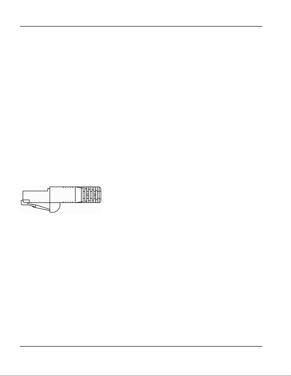
4 – Maintenance and Diagnostics
Diagnostic tests
Diagnostic tests
Machine interface tests
You can perform diagnostic tests with the following connectors (in kit 228510) and Phoenix software to test the interface
ports on the EDGE Pro Picopath CNC:
• LAN and Hypernet (228503)
• Serial interface (228504)
• USB (228505)
• I/O (228500 – white, 228501 – orange)
• Axes (228499)
• THC (228537)
To begin an interface test:
1. From the Main screen, choose Setups > Diagnostics > Machine Interface.
2. Enter the Machine password.
3. On the Machine Interface screen, choose the connector you want to test on the image of the CNC.
4. Follow the instructions in the following topics and on the individual test screens.
LAN and Hypernet tests
The LAN and Hypernet tests both use the same tester, shown in Figure 22.
Figure 22 LAN and Hypernet tester
Conduct this test if:
• The CNC is not communicating with the ArcGlide or plasma system.
• The CNC is not communicating with the local area network.
To test a LAN or Hypernet port:
1. On the Machine Interface screen, choose the LAN or Hypernet port.
2. Follow the instructions on the screen to plug in the tester.
3. Choose Test on the Hypernet or LAN test screen. A message informs you if the test is successful.
4. If either test fails, run the test on the motherboard. If the test fails again, replace the internal cable (223010, 223011,
or both).
5. Repeat the test. If the test fails again, replace the motherboard (141110).
68 EDGE Pro Picopath CNC Instruction Manual 807630
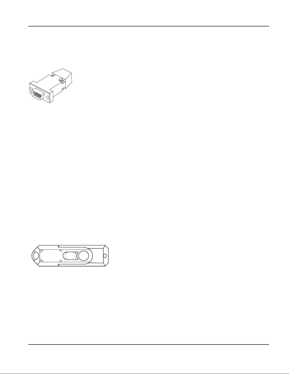
4 – Maintenance and Diagnostics
Diagnostic tests
Serial test
The EDGE Pro is equipped with two serial ports. Serial 1 and 2 support RS-422 or RS-232 communications, depending
on the jumper position. For more information, see Utility and serial isolation board (141307) on page 103.
Figure 23 Serial tester
Conduct this test if:
• Processes or information communicated through the serial port are not operating properly.
• The CNC is unable to download files through the serial port.
• The serial link to the plasma supply fails.
To test serial communications with the test hardware:
1. On the Machine Interface screen, choose the serial port you want to test.
2. On the CNC, plug the serial test hardware into the port you selected.
3. Choose Test on the serial test screen. A message informs you if the test is successful.
4. If the test fails, plug the tester into one of the serial ports on the motherboard and choose Test again.
5. If the test passes, contact your table manufacturer to replace the utility and serial isolation board (141307).
6. If the test fails, contact your table manufacturer to replace the motherboard (141110).
If you do not have the hardware tester, use the online serial diagnostic test. Choose Setups > Diagnostics > Ports and
follow the instructions on the screen.
USB test
Use this test to check the USB ports on the front and back of the CNC. The diagnostic software will test the first USB
memory stick that it finds, so it is important to remove all USB memory sticks before conducting this test.
Figure 24 USB tester
Conduct this test if the memory stick is not shown as an option when you try to load or save part programs or update cut
charts, software, or Help.
To test the USB port on the back of the CNC:
1. Verify that no USB memory stick is installed.
2. On the Machine Interface screen, choose the USB port on the back of the CNC.
3. Follow the instructions on the screen to insert the memory stick in the USB port on the back of the CNC.
4. Press Test. A message informs you if the test is successful.
EDGE Pro Picopath CNC Instruction Manual 807630 69
4 – Maintenance and Diagnostics
Diagnostic tests
To repeat this test for the USB port on the front of the CNC:
1. Verify that no USB memory stick is installed.
2. On the Operator Interface screen, choose the USB port on the front of the CNC.
3. Follow the instructions on the screen to insert the memory stick in the USB port on the front of the CNC.
4. Press Test. A message informs you if the test is successful.
If the test fails on a USB port, contact your table manufacturer to replace the motherboard (141110).
I/O test
To test I/O contacts:
1. On the Machine Interface screen, choose the I/O port you want to test.
2. Follow the instructions on the screen to connect the Picopath (white) test plug into the I/O port you selected on the
back of the CNC.
3. Press Test. A message informs you if the test is successful.
4. If the test fails, follow the instructions on the screen to connect the second Picopath (orange) test plug to isolate the
I/O point that is causing the problem.
After the second test, the screen reports the number of the failed input or output. Contact your table manufacturer for
additional assistance.
Axis test
WARNING!
MOVING PARTS CAN CAUSE DAMAGE AND INJURY
To avoid unexpected machine motion and personal injury while using the Drive Diagnostics screen:
1. Disconnect all axis cables from the CNC.
2. De-couple the motor drive mechanics responsible for table and component movement.
This test verifies axis operation. Conduct this test if there is:
• A runaway axis
• No motion
•Erratic motion
• A high number of position errors
• Multiple parts are not cut the correct size
To test an axis:
1. On the Machine Interface screen, choose the axis port you want to test.
2. Follow the instructions on the screen to connect the Picopath (blue, 228499) axis simulator board to the CNC axis
port you selected.
3. On the Machine Interface screen, choose Test. A message informs you if the test is successful.
If the test fails, contact your table manufacturer to check or replace these parts in the following order:
1. Servo board (141254 for 2 axes, 141122 for 4 axes)
2. MCC board (141061)
3. Ribbon cable (223014)
70 EDGE Pro Picopath CNC Instruction Manual 807630

4 – Maintenance and Diagnostics
Diagnostic tests
THC test
This test allows you to verify the operation of the THC 1 and 2 ports, one at a time.
Conduct this test if:
• Nozzle contact is not functioning properly, for example if IHS using ohmic contact is not sensing the
workpiece or is not accurate; if the torch is running into the workpiece during cutting without
retracting; or if the torch is firing in the air.
• Arc voltage feedback is not functioning properly.
• The torch is rising off the workpiece or driving into the workpiece during the first part of a cut after
piercing.
To test a TH C p o r t :
1. On the Machine Interface screen, press the THC port you want to test.
2. Follow the instructions on the screen to connect the THC test cable (228502) to the CNC at the THC port you
selected.
3. On the Machine Interface screen, press Test. A message informs you if the test is successful.
4. If the test fails, contact your table manufacturer to replace the analog board.
Operator console test
Perform these tests if any function on the integrated operator console is not working as expected.
Note: None of the components on the screen allow motion or any action to take place on the CNC or cutting table.
To test the controls on the operator console:
1. On the Machine Interface screen, press the Operator Interface soft key.
2. On the Operator Interface screen, follow the instructions on the screen and in the following steps.
3. To test the USB port, touch it on the picture on the Operator Interface screen then follow the instructions on the
screen.
4. To test the indicator lamps for Station 1 or 2, touch the corresponding light on the picture on the Operator Interface
screen.
EDGE Pro Picopath CNC Instruction Manual 807630 71

4 – Maintenance and Diagnostics
Diagnostic tests
5. You can also operate any component on the operator console of the CNC and watch the corresponding component
on the screen. Verify that the operation of the component on the screen matches what you do on the console.
6. If the test for a single component fails, replace that component.
If multiple components fail, contact your table manufacturer to replace one or all of the following parts:
• Ribbon cable to the operator console board
• Operator console board (141058)
• Utility and serial isolation board (141307)
(223013)
72 EDGE Pro Picopath CNC Instruction Manual 807630
4 – Maintenance and Diagnostics
Troubleshooting
Troubleshooting
Hypertherm assumes that the service personnel performing the troubleshooting are high-level electronic service
technicians who have worked with high-voltage electro-mechanical systems. Knowledge of final isolation troubleshooting
techniques is also assumed.
In addition to being technically qualified, service personnel must perform all tests with safety in mind. See Safety on
page 11 for operating precautions and warnings.
WARNING!
ELECTRIC SHOCK CAN KILL
Disconnect electrical power before performing any maintenance.
Only qualified personnel can work inside the CNC cabinet with AC power connected.
See the Safety section in this manual for more safety precautions.
WARNING!
MOVING PARTS CAN CAUSE DAMAGE AND INJURY
To avoid unexpected machine motion and personal injury, disconnect the motor drive mechanics
responsible for table and component movement before using the Drive Diagnostics screen.
To avoid damage to the THC and motors, use extreme caution when you select the TEST THC soft key
or the TEST ALL soft key on the Drive Diagnostics screen.
CAUTION!
Turn OFF power to the CNC whenever you remove or reconnect a cable.
The procedures on the following pages provide information about solving problems that you could encounter during
operation of your CNC.
EDGE Pro Picopath CNC Instruction Manual 807630 73

4 – Maintenance and Diagnostics
Troubleshooting
Power
The CNC does not turn on when the ON/OFF button is pressed.
1. Verify that the power cord is plugged into the back of the CNC.
2. Verify that the wall circuit breaker is active.
3. Verify that the fuse in the power entry module is functional. Replace it, if necessary (008872).
4. Open the CNC enclosure and verify that the D6 AC lamp is illuminated on the power distribution board.
Seepage96.
5. If the lamp is not illuminated, replace the surge board or the power entry harness (kit 228464). See Surge board
(141134) on page 95 or Power distribution board (141153) on page 96.
6. Verify the connections for the ON/OFF switch on the operator console.
7. Verify that the green LED on the motherboard is illuminated. This LED indicates power is reaching the motherboard.
See page 87. If it is not illuminated, replace the ATX power supply (kit 228473), or contact your table manufacturer
for additional troubleshooting.
8. Check the 2-digit code in the POST display on the motherboard. The 00 code indicates that Windows can boot up;
all other codes indicate that Windows cannot boot up.
9. Verify that the green and white wires from the utility and serial isolation board (141307) are connected to the
motherboard.
10. Contact your table manufacturer.
The “Field power failure” error message is posted on the CNC.
This situation indicates a low output voltage from the CNC field power supply. Usually, low output voltage is caused by a
table I/O short or an overload of the CNC’s built-in power supply and the overload is reported as a fault.
1. Disconnect I/O and axes cables from the CNC to determine if the fault clears to help determine whether the issue is
the table wiring or a component inside the CNC.
2. Verify that the cable between the utility and serial isolation board (141307) and the power distribution board
(141153) is connected at both ends.
3. Verify that all other cables are properly connected.
4. Verify that the ATX power supply is operating.
5. Verify that the LEDs on the power distribution board are illuminated. See page 96.
6. If the LEDs on the power distribution board are not illuminated, replace the board.
The power switch is on and illuminated, but the touchscreen remains black.
1. Verify that the AC power connections are plugged into the touchscreen.
2. Verify that the VGA cable is connected to both the touchscreen and the motherboard.
3. Look at the motherboard to see if there is a BIOS fault (any code except 00).
4. Verify that the ambient temperature is within the operating range of the CNC. See System specifications on page 34.
Operator console
A button, function, or LED on the operator console is not responding when the corresponding switch is activated by the
operator.
1. Choose Setups > Diagnostics > Operator Interface.
2. Move or press any of the components on the physical operator console to verify the proper operation on the CNC
screen.
74 EDGE Pro Picopath CNC Instruction Manual 807630

4 – Maintenance and Diagnostics
Troubleshooting
3. If any of these tests fail:
• Verify that I/O for the operator console is set up correctly in Phoenix software. See Phoenix Software V9 Series
Installation and Setup Manual (806410) for details.
• Replace the individual component on the operator console (see Parts List for the appropriate part number).
Input failure
• An input is in an unexpected state or fails to change state.
• The table is not performing as set up when reaching limit switches.
• A continuous fault is occurring and will not clear.
For Picopath interfaces with the hardware testers (228500 and 228501), see Diagnostic tests on page 68.
a. Picopath interface board (141122 – 4 axis, 141254 – 2 axis)
b. Ribbon cable (223015)
c. MCC board (141061)
Output failure
• An output is in an unexpected state or fails to change state.
• A continuous fault is occurring and will not clear.
For Picopath interfaces with the hardware testers (228500 and 228501), see Diagnostic tests on page 68.
For Picopath interfaces without the testers:
1. Power off the table and disconnect interface cables from the back of the CNC.
2. Choose Setups > Diagnostics > I/O and enter the Machine password.
3. Exercise the output through the CNC to see if the output reacts as expected. If an output point fails, replace
components in the following order and repeat the test after each replacement:
a. Picopath interface board (141122 – 4 axis, 141254 – 2 axis)
b. The MCC board (141061)
c. Picopath I/O ribbon cable (223015)
4. If the output point still fails, a table component has failed. Contact your table manufacturer.
Hypernet connection
Communications with components connected to the Hypernet are not working properly. See Diagnostic tests on
page 68.
LAN connection
• Downloading part programs over the LAN is not working properly.
• Previously mapped network drives are not shown when trying to load a part program.
If you have the test hardware, see Diagnostic tests on page 68.
If you do not have the test hardware, contact your local network administrator to test the device and local network
connections.
EDGE Pro Picopath CNC Instruction Manual 807630 75

4 – Maintenance and Diagnostics
Troubleshooting
Motion issues
• Motion is erratic.
• An axis “runs away”.
• No motion is observed.
• There is a high number of position errors.
• Parts may not be to tolerance.
For Picopath interfaces with the servo hardware tester (228499)
If you have the servo hardware tester, you can test the servo interface in two procedures:
1. Check the CNC internal hardware.
2. Check the table setup.
To check the CNC internal hardware:
1. Shut down the CNC and disconnect AC power.
2. Disconnect all axis cables from the rear panel of the CNC.
3. Reconnect AC power and restart the CNC.
4. In Phoenix, choose Setups > Diagnostics > Machine Interface > and enter the Machine password.
5. Test each of the axis connectors on the back of the CNC by pressing one of the axis connectors on the touchscreen
and following the on-screen instructions.
• If the test passes, the CNC hardware is functional. The problem is either with the CNC setup parameters or
table components. Verify your setup parameters and proceed with the next procedure to check the table setup.
• If the test fails, the problem is with one of the CNC components. Verify that clean and field power LEDs are
illuminated on the power distribution board (141153, see page 96).
6. Contact your table manufacturer for additional troubleshooting. You may need to replace one or more of the following
components. Repeat the test after each replacement:
a. Servo board (141254 for 2 axes, 141122 for 4 axes)
b. MCC board (141061)
c. Ribbon cable (223014)
To check the table setup:
1. Shut down the CNC and disconnect AC power.
2. Reconnect all axis cables to the rear panel of the CNC.
3. To avoid potential damage to the table and components, de-couple all motor shafts to prevent table motion before
performing the next steps.
4. Reconnect AC power and restart the CNC.
5. Choose Setups > Diagnostics > Drives and Motors and enter the Machine password.
6. Enter the following values:
• Pulse Type = Single
• Pulse Direction = Alternating
• Pulse Magnitude = 1 V
• Pulse Duration = 0.5 seconds
7. Press the Test Transverse and Test Rail soft keys, one at a time, and verify that the motors move in both directions for
each test.
• If there is no movement in any of the axes, in any direction, check the axis setup parameters in Phoenix software.
• If there is no movement in one of the directions, troubleshoot the appropriate motor, drive amplifier, and electrical
connections.
76 EDGE Pro Picopath CNC Instruction Manual 807630

4 – Maintenance and Diagnostics
Troubleshooting
• If you see appropriate motion in all directions, proceed to Step 8.
8. Repeat Step 7. This time, observe the transverse and rail position coordinates in the Watch Window.
• If these coordinates are changing in a repeatable manner, all components are working as expected and the table
should be re-tuned.
• If the coordinates are not changing when the table is moving, the encoders may be faulty and should be
replaced.
For Picopath interfaces without the servo tester:
1. To avoid potential damage to the table and components, de-couple all motor shafts to prevent table motion before
performing the next steps.
2. In Phoenix, choose Setups > Diagnostics > Drives and Motors > and enter the Machine password.
3. Enter the following values:
• Single for Pulse Type
• Alternating for Pulse Direction
• Pulse Magnitude = 1 V
• Pulse Duration = 0.5 seconds
4. Press the Test Transverse and Test Rail soft keys, one at a time, and verify that the motors move in both directions for
each test.
• If there is no movement in any of the axes, in any direction, check the axis setup parameters in Phoenix software.
• If you see appropriate motion in all directions, the table components are not the problem. Proceed to Step 6.
• If there is no movement in one of the directions, take note of which motor or axis it is and proceed to Step 5.
5. In the back of the CNC, switch the Axis X/Y and Axis W/Z cables, and repeat the test starting with Step 2.
• For 2-axis systems, you must switch the motors physically. If the problem stays with the motor, check the
electrical wiring before you replace the affected motor or drive amplifier.
• If the problem changes motors, verify that clean and field power LEDs are illuminated on the power distribution
board (141153, see page 96).
6. Contact your table manufacturer for additional troubleshooting. You may need to replace one or more of the following
components. Repeat the test after each replacement:
a. Servo board (141254 for 2 axes, 141122 for 4 axes)
b. MCC board (141061)
c. Ribbon cable (223014)
THC 1 and THC 2
• Nozzle contact is not functioning properly.
• IHS using ohmic contact is not sensing the workpiece properly.
• The torch is firing in the air.
• The torch is running into the workpiece without retracting.
• Arc voltage feedback is not functioning as expected.
For Picopath interfaces with the THC tester (228537):
1. In Phoenix, choose Setups > Diagnostics > Machine Interface and enter the Machine password.
2. Test each of the THC connectors on the back of the CNC by pressing one of the THC connectors on the
touchscreen and following the on-screen instructions. If the test passes, contact Technical Service for additional
troubleshooting.
3. If the test fails, replace the Analog board (141125) and repeat the test.
4. If the test fails again, contact your table manufacturer.
EDGE Pro Picopath CNC Instruction Manual 807630 77

4 – Maintenance and Diagnostics
Troubleshooting
Serial communication issues
• Processes and information communicated through the serial ports are not operating properly.
• P-S link fail messages are occurring.
• You cannot download files over a configured serial port.
• HPR-link fail messages are occurring when the CNC uses serial communications with the HPR.
Note: This test only works with RS-422 configured ports. Refer to Utility and serial isolation board (141307) on
page 103 for information about how to determine whether the port is set up for RS-422.
With the serial port hardware tester
1. In Phoenix, choose Setups > Diagnostics > Machine Interface and enter the Machine password.
2. Test each of the serial port connectors on the back of the CNC by pressing one of the serial port connectors on the
touchscreen and following the on-screen instructions.
3. If the test passes, verify that the ports are set up for RS-422 or RS-232, as needed by the external components
connected to the serial port.
4. If the test fails, replace the following items one at a time and repeat the tests after each replacement:
a. Utility and serial isolation board (141307)
b. Ribbon cable (229245, 229249, or 229250)
c. Motherboard (141110)
Without the serial port tester
1. Verify that the serial jumpers on the utility and serial isolation board (141307) are set properly, for RS-422 or
RS-232, for the device you are communicating with.
2. In Phoenix, choose Setups > Diagnostics > Ports and perform the on-screen loop-back test.
3. If the loop-back test fails, verify the connections between the following components:
• Serial isolation board or utility and serial isolation board (141307)
• Ribbon cable (for serial board only, 229245, 229249, or 229250)
• Motherboard (141110)
USB port
If the CNC is not recognizing a device in a USB port:
1. Verify that another computer can read the memory stick.
2. Verify that no other memory sticks are installed. The CNC can only read one memory stick at a time.
3. Verify that all files are on the root of the memory stick. The CNC cannot read files inside folders.
4. In Phoenix, choose one of the following paths:
• Setups > Diagnostics > Machine Interface and enter the Machine password
• Setups > Diagnostics > Operator Interface
5. Press the USB port on the operator console or rear panel on the touchscreen and follow the on-screen instructions.
6. If the test in Step 5 fails, repeat the test using the other USB port (operator console or rear panel).
7. If the test in Step 6 fails, install the memory stick directly into the motherboard and repeat the test.
8. If the test in Step 7 fails, contact Technical Service. The problem is with the motherboard, the USB ports on the
CNC, or the connection cables.
78 EDGE Pro Picopath CNC Instruction Manual 807630

4 – Maintenance and Diagnostics
Troubleshooting
Cut quality or plasma performance issues
Press the “Cutting Tips” soft key on the Main screen and follow the on-screen instructions to improve cut quality.
The CNC feels excessively warm
1. Verify that the external fan is running. If it is running slowly, clean the fan.
2. If the fan is not running and ambient temperature is above 20° C (70° F):
a. In Phoenix, choose Setups > Password and enter the FANON password to verify that the fan is enabled.
b. Verify that the internal harness between the fan and the utility board is connected.
c. Remove the fan shroud and verify that the connections to the fan are in place.
d. Replace the external fan (kit 228472).
3. If the external fan is running and the CNC is still excessively warm, open the front door of the CNC and verify that the
internal chassis fan is running. If the fan is not running, replace the internal fan (kit 228474).
Loading files
The CNC is loading files slower than when it was first installed or is taking a long time to perform operations that used to
happen faster.
1. In Phoenix, choose Setups > Password and enter the Special password, then choose System.
2. If all five numbers on the screen are blue, the CNC is performing as designed.
3. If any of the five numbers on the screen are red, the CNC is operating more slowly than is needed for peak
performance.
a. Restart the CNC. After 5 minutes, choose Setups > Password and enter the Special Password, then choose
System and recheck the numbers. If the five numbers are blue, the CNC is operating as expected.
b. If any of the five numbers are red, there may be other programs that are running on the CNC besides Phoenix
that are negatively affecting performance. Close these other programs. Call Technical Service for additional
troubleshooting.
4. If the CNC is having difficulty connecting to the network, files will load slowly. Verify network connections.
EDGE Pro Picopath CNC Instruction Manual 807630 79

4 – Maintenance and Diagnostics
Troubleshooting
Wireless troubleshooting
Refer to the Phoenix Software V9 Series Installation and Setup Manual (806410) for information about networking.
Follow these guidelines if you are experiencing problems using the wireless network on your CNC:
• The wireless network board (141223) requires a bus mastering slot on the motherboard. On the
motherboard (141110), PCI slot 1 is not a bus mastering slot. Verify that the wireless board is installed
in PCI slot 2.
• The wireless network board conforms to 802.11N and 802.11G standards and connects to either a
wireless G or N local area network (LAN). It provides wireless G or better performance for part
program downloads, remote help, or other network tasks.
• An 802.11G wireless network can operate at reasonable speeds up to 38 m (125 ft) from the wireless router or
access point, even if the path between the CNC and the access point is obstructed with a wall or door.
• An 802.11N wireless network can operate at reasonable speeds up to 70 m (230 ft) from the wireless router or
access point. However, 802.11N communication requires a clear line of sight between antennas.
• When in doubt, use the 802.11G wireless network connection.
Note: The network must be set to broadcast its SSID for it to be visible as a connection.
• Make sure the wireless network board appears in the Windows Device Manager under the
“Network Adapters” heading, and does not have a yellow ! or ? next to it.
• Use the Windows Network Connections Manager to locate your router or wireless network access
point. Choose Start > Settings > Network Connections.
• If the network connection wizard does not list any company wireless networks, check the network
availability using a Windows XP laptop or other wi-fi device to verify the router or access point
connection is available at that physical location.
• Signal strength diminishes with distance. A wireless network connection does not require 100% signal
strength to be effective (shown as four solid bars on the screen). If the Network Connections Manager
shows two or three signal strength bars, the network connection is reasonable.
• If the connection speed frequently dips below 24 Mbs or signal strength dips below two bars, move
the wireless router or access point closer to the CNC, or add another access point closer to the CNC.
• For best network performance, minimize the number of clients on the wireless network.
• Avoid connecting slower wireless devices to the network (for example, 802.11B devices) as the entire
network may degrade to that level of performance.
80 EDGE Pro Picopath CNC Instruction Manual 807630
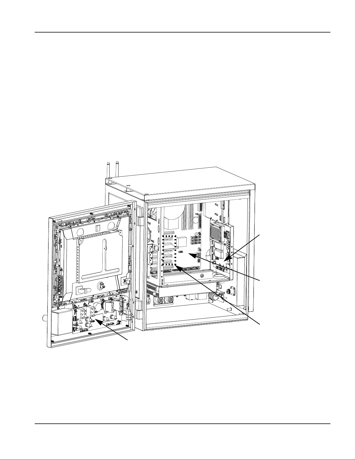
4 – Maintenance and Diagnostics
Power distribution PCB
Motherboard
Operator console PCB
PCI slots (5)
Component locations and information
Component locations and information
The following pages provide details about the major components of the EDGE Pro Picopath CNC. Refer to Parts List for
the corresponding replacement kits and part numbers.
Note: Use the instructions in Replacement Parts for EDGE Pro CNC Field Service Bulletin (806440) to replace
parts in the EDGE Pro CNC. In addition:
• Use common safety precautions when replacing parts in the CNC.
• Turn off electrical power to the CNC before opening panels on the enclosure.
• Use common safety precautions when handling printed circuit boards.
• Store PC boards in anti-static containers.
• Wear a grounded wrist strap when handling PC boards.
Figure 25 Front internal view of the EDGE Pro Picopath CNC
EDGE Pro Picopath CNC Instruction Manual 807630 81
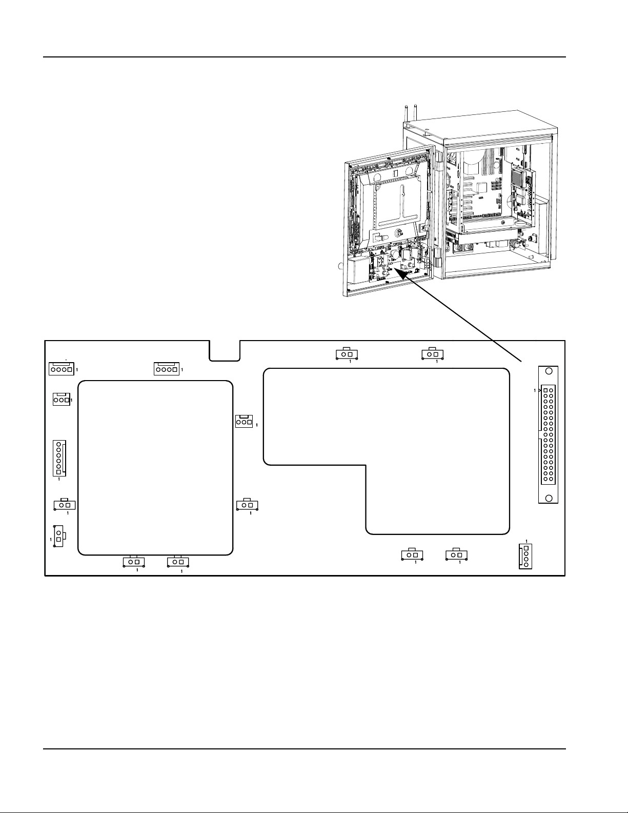
4 – Maintenance and Diagnostics
J1
J2
J3
J4
J5 J6
J7
J8
J10
J9
J11
J13
J12
J14 J15
J16
Operator console board (141058)
Operator console board (141058)
Figure 26 Operator console board
82 EDGE Pro Picopath CNC Instruction Manual 807630

4 – Maintenance and Diagnostics
Operator console board (141058)
Tabl e 5 Pin outs f or J1 – J16
Pin no. Signal Pin no. Signal Pin no. Signal
J1 Station 2 J7 To utility PCB J8 Joy stick
1 Auto select 2 1 Start 1 Up
2 Logic ground 2 Stop 2 Down
3 Manual select 2 3 Manual 3 Left
4 Not used 4 Forward on path 4 Right
J2 Jog potentiometer
1 Logic ground 6 Joystick +Y 6 Logic ground
2 Analog (jog speed) 7 Joystick -Y
3 4.096 V reference 8 Joystick -X 1 Logic ground
J3 Station 1
1 Auto select 1 10 Logic ground
2 Logic ground 11 Logic ground 1 Logic ground
3 Manual select 1 12 Not connected
4 Not used 13 Ground
J4 Cut potentiometer
1 Logic ground 15 Logic ground 2 Manual switch
2 Analog (cut speed) 16 Logic ground
3 4.096 V reference 17 Not connected
J5 Stop
1 Logic ground 19 Manual select 1
2 Stop switch 20 Raise torch 1 1 Logic ground
J6 Start
1 Logic ground 22 Auto select 2
2 Start switch 23 Manual select 2 1 Logic ground
5 Backward on path 5 Logic ground
J9 Raise 2
9 Joystick +X 2 Raise torch 2
J10 Raise 1
2 Raise torch 1
Front panel ID 1
Front panel ID 0
14 Not connected
Front panel ID 1
1 Logic ground
J11 Manual
J12 Lower 2
1 Logic ground
Front panel ID 2
18 Auto select 1 2 Lower torch 2
J13 Lower 1
21 Lower torch 1 2 Lower torch 1
J14 Forward
24 Raise torch 2 2 Forward on path
25 Lower torch 2
26 Station enable LED1 1 Logic ground
27 Station enable LED2 2 Backward on path
28 Motherboard On/Off 1
29 Motherboard On/Off 2 1 Logic +12 V
30 Cut speed 2 Motherboard On/Off 1
31 Jog speed 3 Motherboard On/Off 2
32 4.096 V Reference 4 Logic ground
33 Logic +5 V
34 Logic +12 V
J15 Back
J16 Power switch
EDGE Pro Picopath CNC Instruction Manual 807630 83
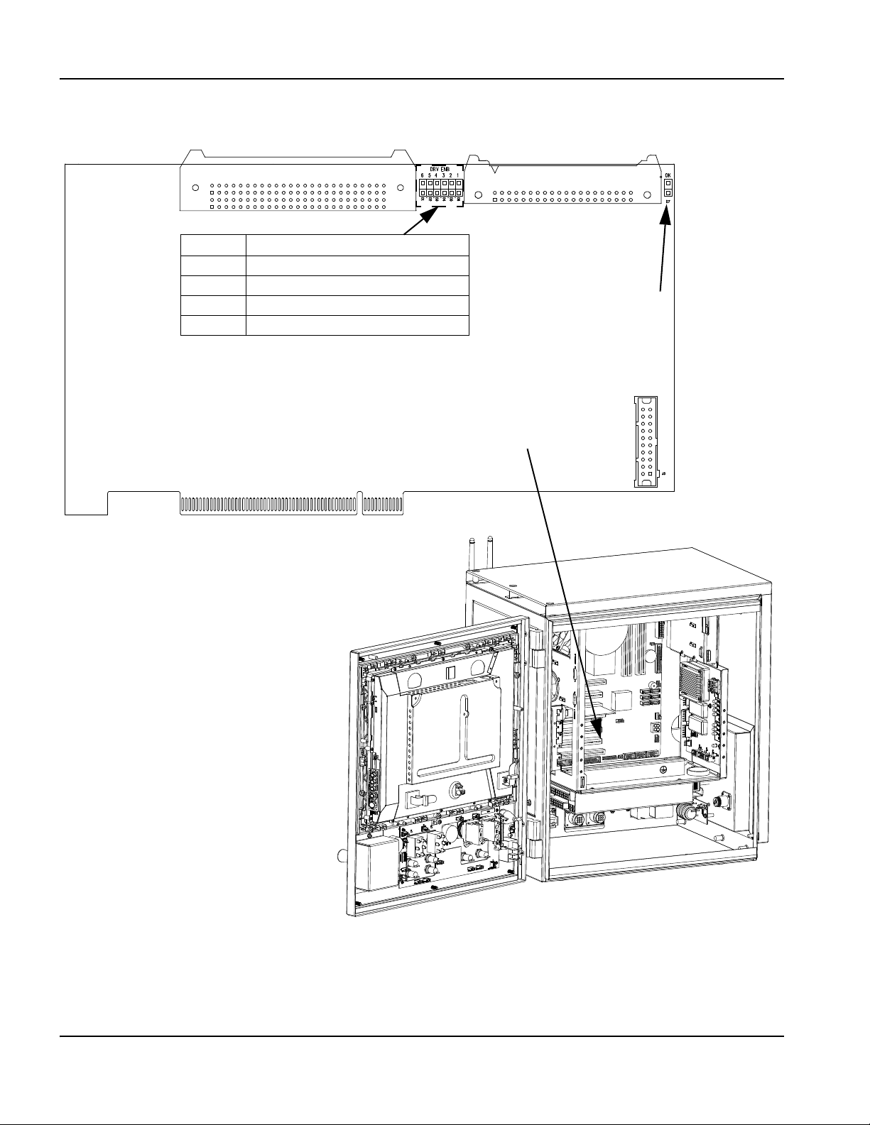
4 – Maintenance and Diagnostics
LED Signal
D3 Axis 4 enabled
D4 Axis 3 enabled
D5 Axis 2 enabled
D6 Axis 1 enabled
D7
Watch dog LED ON = enabled
J1
I/O 1 – 12
J2 Axis 1 – 4
Installed in PCI slot 5 on the motherboard
4-Axis MCC board (141061)
4-Axis MCC board (141061)
Figure 27 4-Axis MCC board connectors and LEDs
84 EDGE Pro Picopath CNC Instruction Manual 807630

Tabl e 6 Pin outs f or J1 – I/ O 1 – 12
Pin no. Signal Pin no. Signal
1 Input 1 26 Output 13
2 Output 1 27 Input 14
3 Input 2 28 Output 14
4 Output 2 29 Input 15
5 Input 3 30 Output 15
6 Output 3 31 Input 16
7 Input 4 32 Output 16
8 Output 4 33 Input 17
9 Input 5 34 Output 17
10 Output 5 35 Input 18
11 Input 6 36 Output 18
12 Output 6 37 Input 19
13 Input 7 38 Output 19
14 Output 7 39 Input 20
15 Input 8 40 Output 20
16 Output 8 41 Input 21
17 Input 9 42 Output 21
18 Output 9 43 Input 22
19 Input 10 44 Output 22
20 Output 10 45 Input 23
21 Input 11 46 Output 23
22 Output 11 47 Input 24
23 Input 12 48 Output 24
24 Output 12 49 Ground
25 Input 13 50 Ground
4 – Maintenance and Diagnostics
4-Axis MCC board (141061)
EDGE Pro Picopath CNC Instruction Manual 807630 85

4 – Maintenance and Diagnostics
4-Axis MCC board (141061)
Table 7 Pinouts for J2 – axis 1 – 4
Pin no. Signal Pin no. Signal
1 /Axis 1 enable 21 Axis 5B Ch
2 /Axis 2 enable 22 Axis 5Z Ch
3 /Axis 3 enable 23 Axis 6A Ch
4 /Axis 4 enable 24 Axis 6B Ch
5 /Axis 5 enable 25 Axis 6Z Ch
6 /Axis 6 enable 26 Logic ground
7 /Watchdog enable 27 Logic ground
8 Axis 1A 28 Analog common
9 Axis 1B 29 Axis 1 analog
10 Axis 1Z 30 Axis 2 analog
11 Axis 2A 31 Axis 3 analog
12 Axis 2B 32 Axis 4 analog
13 Axis 2Z 33 Axis 5 analog
14 Axis 3A 34 Axis 6 analog
15 Axis 3B 35 Logic ground out
16 Axis 3Z 36 Logic +5 V
17 Axis 4A 37 Logic +5 V
18 Axis 4B 38 Logic +12 V
19 Axis 4Z 39 Logic -12 V
20 Axis 5A 40 Logic ground
86 EDGE Pro Picopath CNC Instruction Manual 807630
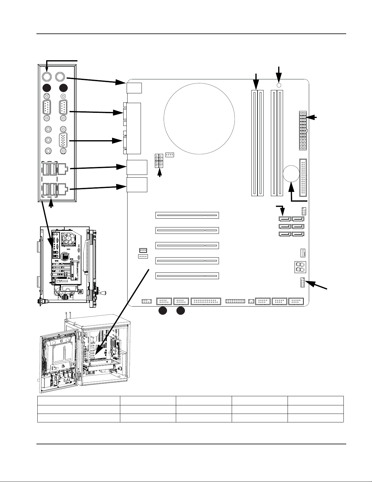
Motherboard (141110)
4
3
2
1
PCI slot 2 PCI slot 3 PCI slot 4 PCI slot 5
Picopath 4-axis Wireless (141223) not used Utility (141307) MCC (141061)
Picopath with Sensor THC Wireless (141223) Utility (141307) Analog (141125) MCC (141061)
PCI 3
PCI 4
PCI 5
PCI slots
Motherboard
ON/OFF
signals
POST display
(ready state is 00)
SATA connector
for the hard drive
Battery for
CMOS
memory
ATX 12 V power connector
Chassis fan connector
CPU
DIMM1 – 1 GB RAM
ATX power
connector
PS/2 Keyboard
PS/2 Mouse
Serial ports
VGA port
LAN port
Hypernet port
USB ports
PCI 2
PCI 1 (not used)
Power LED
1
COM 1
2
COM 2
3
COM 3
4
COM 4
Figure 28 Motherboard
4 – Maintenance and Diagnostics
Motherboard (141110)
EDGE Pro Picopath CNC Instruction Manual 807630 87
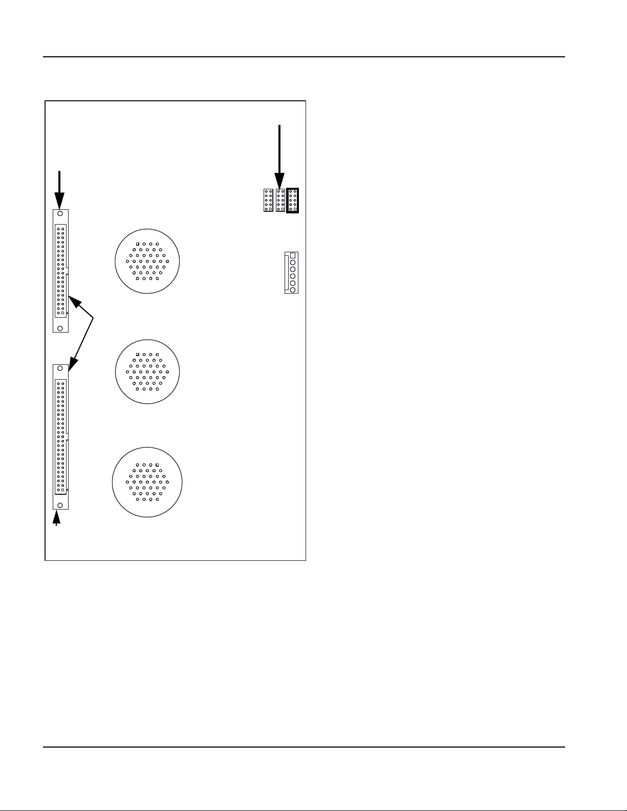
4 – Maintenance and Diagnostics
J13 – Jumper for 12 V encoders
sourced
J12 – Jumper for 5 V encoders sourced
J14 – Jumper for
external encoder voltage
J11 – To power distribution board
J6 – Z and W axis drive
encoder
J7 – X and Y axis drive
encoder
J8 – I/O 1 – 12
To MCC 4-axis board
J3 — To servo ribbon cable
J5 – To digital I/O ribbon
1
4
34
37
1
4
34
37
1
4
3437
4-Axis servo and 12 I/O board (141122)
4-Axis servo and 12 I/O board (141122)
Figure 29 Servo and I/O board
88 EDGE Pro Picopath CNC Instruction Manual 807630

4 – Maintenance and Diagnostics
4-Axis servo and 12 I/O board (141122)
Table 8 J3 – Servo ribbon cable
Pin no. Signal Pin no. Signal
1 /Axis 1 enable 21 Not connected
2 /Axis 2 enable 22 Not connected
3 /Axis 3 enable 23 Not connected
4 /Axis 4 enable 24 Not connected
5 Not connected 25 Not connected
6 Not connected 26 Ground
7 /Watchdog enable 27 Ground
8 Axis 1A 28 Analog common
9 Axis 1B 29 Axis 1 analog
10 Axis 1Z 30 Axis 2 analog
11 Axis 2A 31 Axis 3 analog
12 Axis 2B 32 Axis 4 analog
13 Axis 2Z 33 Not connected
14 Axis 3A 34 Not connected
15 Axis 3B 35 Ground
16 Axis 3Z 36 +5 V
17 Axis 4A 37 +5 V
18 Axis 4B 38 +12 V
19 Axis 4Z 39 -12 V
20 Not connected 40 Ground
EDGE Pro Picopath CNC Instruction Manual 807630 89

4 – Maintenance and Diagnostics
4-Axis servo and 12 I/O board (141122)
Table 9 Pinouts for J5 digital I/O ribbon
Pin no. Signal Pin no. Signal
1 Input 1 26 Not connected
2 Output 1 27 Not connected
3 Input 2 28 Not connected
4 Output 2 29 Not connected
5 Input 3 30 Not connected
6 Output 3 31 Not connected
7 Input 4 32 Not connected
8 Output 4 33 Not connected
9 Input 5 34 Not connected
10 Output 5 35 Not connected
11 Input 6 36 Not connected
12 Output 6 37 Not connected
13 Input 7 38 Not connected
14 Output 7 39 Not connected
15 Input 8 40 Not connected
16 Output 8 41 Not connected
17 Input 9 42 Not connected
18 Output 9 43 Not connected
19 Input 10 44 Not connected
20 Output 10 45 Not connected
21 Input 11 46 Not connected
22 Output 11 47 Picopath ID (0=True)
Hypath ID (NC=1=False)
23 Input 12 48 Not connected
24 Output 12 49 Not connected
25 Not connected 50 Ground
90 EDGE Pro Picopath CNC Instruction Manual 807630

4 – Maintenance and Diagnostics
4-Axis servo and 12 I/O board (141122)
Table 10 Pinouts for J6 – axes 3 and 4 (Z and W)
Pin no. Signal Pin no. Signal
1 Encoder voltage 20 Analog common
2 Encoder voltage 21 Axis 3 (Z), encoder /B
3 Encoder common 22 Axis 3 (Z), encoder Z
4 Encoder voltage 23 Axis 4 (W), encoder /Z
5 Axis 4 (W), encoder A 24 Axis 3 (Z), enable in
6 Encoder common 25 Axis 3 (Z), enable out
7 Ground 26 Axis 4 (W), enable in
8 Encoder common 27 Axis 4 (W), enable out
9 Axis 3 (Z), encoder A 28 Axis 3 (Z), encoder /Z
10 Axis 4 (W), encoder B 29 Axis 4 (W), reference+
11 Axis 4 (W), encoder /A 30 Analog common
12 Ground 31 Ground
13 Ground 32 Analog common
14 Axis 3 (Z), encoder /A 33 Axis 3 (Z), reference+
15 Axis 3 (Z), encoder B 34 Analog voltage +
16 Axis 4 (W), encoder Z 35 Analog voltage -
17 Axis 4 (W), encoder /B 36 Analog voltage -
18 Analog common 37 Analog voltage +
Table 11 Pinouts for J7 – axes 1 and 2 (X and Y)
Pin no. Signal Pin no. Signal
1 Encoder voltage 20 Analog common
2 Encoder voltage 21 Axis 1 (X), encoder /B
3 Encoder common 22 Axis 1 (X), encoder Z
4 Encoder voltage 23 Axis 2 (Y), encoder /Z
5 Axis 2 (Y), encoder A 24 Axis 1 (X), enable in
6 Encoder common 25 Axis 1 (X), enable out
7 Ground 26 Axis 2 (Y), enable in
8 Encoder common 27 Axis 2 (Y), enable out
9 Axis 1 (X), encoder A 28 Axis 1 (X), encoder /Z
10 Axis 2 (Y), encoder B 29 Axis 2 (Y), reference+
11 Axis 2 (Y), encoder /A 30 Analog common
12 Ground 31 Ground
13 Ground 32 Analog common
14 Axis 1 (X), encoder /A 33 Axis 1 (X), reference+
15 Axis 1 (X), encoder B 34 Analog voltage +
16 Axis 2 (Y), encoder Z 35 Analog voltage -
17 Axis 2 (Y), encoder /B 36 Analog voltage -
18 Analog common 37 Analog voltage +
19 Ground
EDGE Pro Picopath CNC Instruction Manual 807630 91

4 – Maintenance and Diagnostics
4-Axis servo and 12 I/O board (141122)
Table 12 Pinouts for J8 – I/O 1 – 12
Pin no. Signal Pin no. Signal
1 Input 1 20 Watchdog contact B
2 Input 2 21 Output 1
3 Input 3 22 Output 2
4 Input 4 23 Output 3
5 Input 5 24 Output 4
6 Input 6 25 Output 5
7 Input 7 26 Output 6
8 Input 8 27 Output 7
9 Input 9 28 Output 8
10 Input 10 29 Output 9
11 Input 11 30 Output 10
12 Input 12 31 Output 11
13 Not connected 32 Output 12
14 +24 V 33 Shield
15 +24 V 34 +24 V
16 Not connected 35 +24 V
17 24 V common 36 24 V common
18 24 V common 37 24 V common
19 Watchdog contact A
92 EDGE Pro Picopath CNC Instruction Manual 807630

4 – Maintenance and Diagnostics
4-Axis servo and 12 I/O board (141122)
Table 13 Pinouts for J11 – J14
Pin no. Signal Pin no. Signal
J11 – To power distribution board J13 – Jumper for 12 V encoders sourced
1 Field ground 1 +Ve
2 +24 V 2 +12 Vf
3 +5 V 3 +Va
4 –12 V 4 +12 Vf
5 +12 V 5 -Va
6 Field ground 6 -12 Vf
J12 – Jumper for 5 V encoder sourced
1 +Ve 8 +24 Vf
2 +5 Vf 9 /Axis watchdog
3 +Va 10 /Axis watchdog header
4 +Va
5 -Va 1 +Ve
6 -12 Vf 2 Not connected
7 +24 V 3 +Va
8 +24 Vf 4 Not connected
9 /Axis watchdog 5 -Va
10 /Axis watchdog header 6 Not connected
7 +24 V
J14 – Jumper for external encoder voltage
7 +24 V
8 Not connected
9 /Axis watchdog
10 /Axis watchdog header
EDGE Pro Picopath CNC Instruction Manual 807630 93

4 – Maintenance and Diagnostics
J1 THC 1
J2 THC 2
Analog board (141125)
Analog board (141125)
Figure 30 Analog board
Table 14 Pinouts for J1 and J2
Pin no. J1 – to THC1 J2 – to THC 2 Signal
1 Common Common Common
2 Input 5+ Input 6+ Nozzle contact sense+ (relay contact)
3 Input 5- Input 6- Nozzle contact sense- (relay contact)
4 Output 1 Output 3+ Nozzle contact enable+ (relay contact)
5 Output 1- Output 3- Nozzle contact enable- (relay contact)
6 Analog input 1+ Analog input 2+ THC+
7 Analog input 1- Analog input 2- THC-
8 Output 2+ Output 4+ Hold ignition (relay contact)
9 Output 2- Output 4- Hold ignition (relay contact)
10 Shield Shield Shield
Note:
• Analog inputs for the speed pots are rated at 0 to +10 VDC.
• The Series 1 PCI analog card is named PCI-AIC Rev A on the CNC Information Diagnostic screen in
Phoenix software.
94 EDGE Pro Picopath CNC Instruction Manual 807630

Surge board (141134)
J1 From AC power inlet J2 To power distribution board
Figure 31 Surge board
4 – Maintenance and Diagnostics
Surge board (141134)
Table 15 Pinouts for J1 and J2
Pin no. Signal
J1 – From AC power inlet
1 Neutral
2 Line
J2 – To power distribution board (J10)
1 Neutral
2 Line
3 Ground
EDGE Pro Picopath CNC Instruction Manual 807630 95
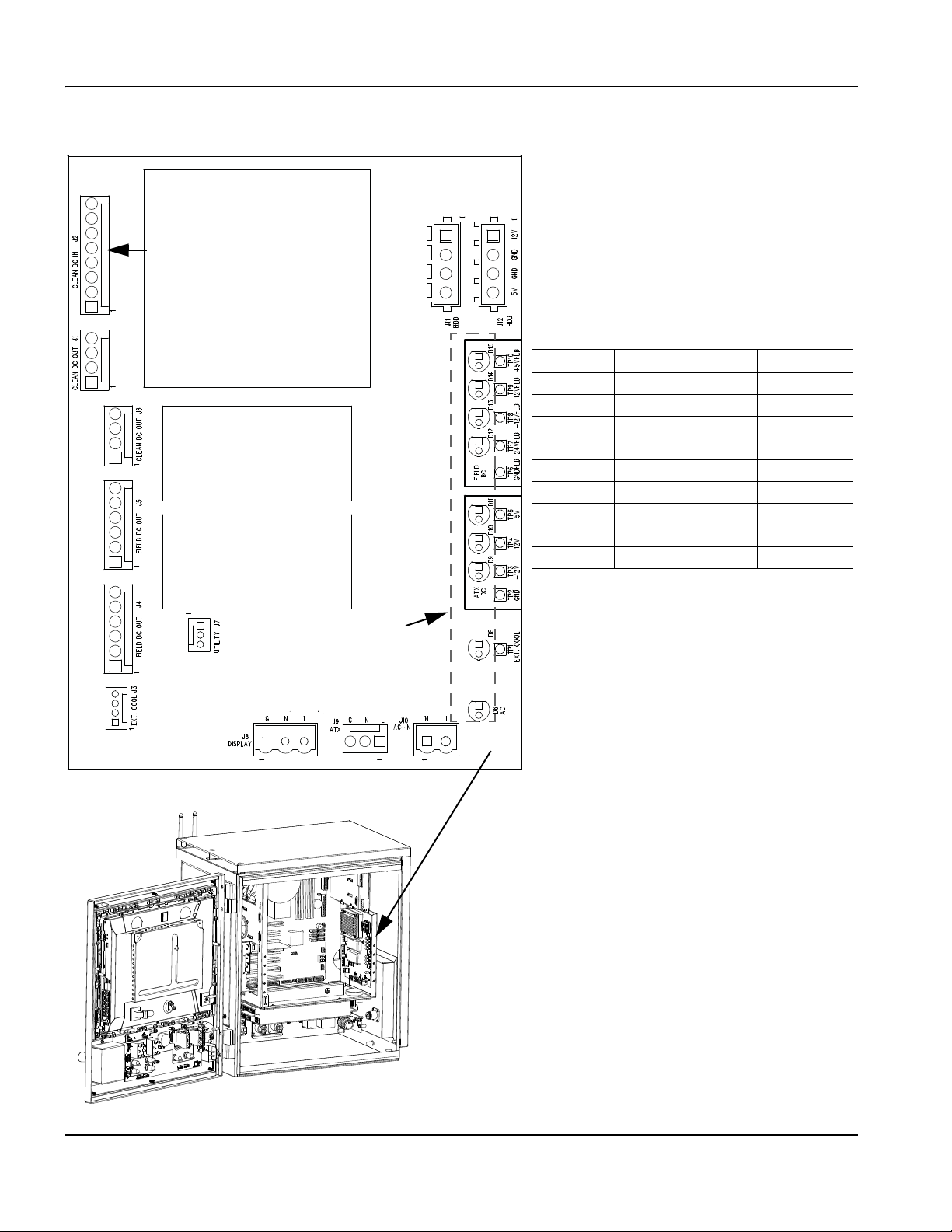
4 – Maintenance and Diagnostics
Note: LED D6 is illuminated at full
brightness when 220 VAC is supplied to
the CNC and at half brightness when
120 VAC is supplied.
LED Signal Color
D15 +5 V Field DC Green
D14 12 V Field DC Green
D13 -12 V Field DC Green
D12 24 V Field DC Green
D11 5 V ATX DC Green
D10 12 V ATX DC Green
D9 -12 V ATX DC Green
D8 External fan Green
D6 AC power Green
LEDs 6 – 15
See table, right, for signals
From the ATX power supply
Power distribution board (141153)
Power distribution board (141153)
Figure 32 Power distribution board
96 EDGE Pro Picopath CNC Instruction Manual 807630

4 – Maintenance and Diagnostics
Power distribution board (141153)
Table 16 Pinouts for J1 – J12
Pin no. Signal Pin no. Signal
J1 – Clean DC out J6 – Clean DC out
1 Logic +5 V fused 1 Logic +5 V fused
2 Logic -12 V fused 2 Logic -12 V fused
3 Logic +12 V fused 3 Logic +12 V fused
4 Logic ground 4 Logic ground
J2 – Clean DC in J7 – Utility
1 Logic +5 V 1 Fan disable
2 Logic +12 V 2 Field power good
3 Logic +12 V 3 Logic ground
4 Logic +12 V
5 Logic -12 V 1 Earth ground
6 Logic ground 2 Line 2
7 Logic ground 3 Line 1
8 Logic ground
J3 – External cooling
1 Fan +24 V 2 Line 2
2 Fan interlock 2 3 Earth ground
3 Fan interlock 1
4 Field ground 1 Line 2
J4 – Field DC out
1 Field ground
2 +24 V 1 Logic +12 V
3 +5 V 2 Logic ground
4 -12 V 3 Logic ground
5 +12 V 4 Logic +5 V
6 Field ground
1 Line 1
J10 – AC in (from surge board J2)
2 Line 1 switched
J5 – Field DC out
1 Field ground
2 +24 V
3 +5 V
4 -12 V
5 +12 V
6 Field ground
J8 – Display
J9 – ATX power supply
J11 and J12 HDD
EDGE Pro Picopath CNC Instruction Manual 807630 97
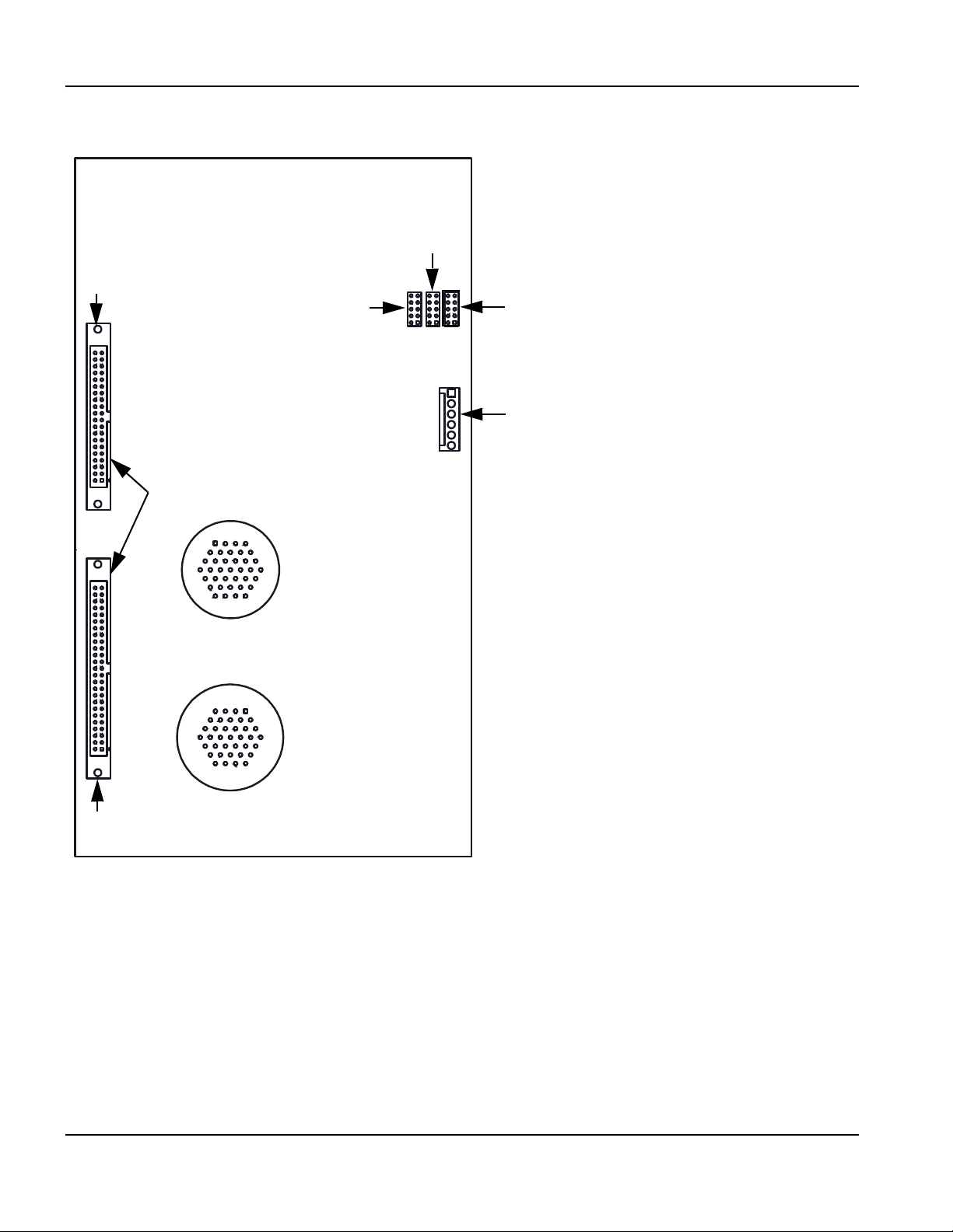
4 – Maintenance and Diagnostics
J13 – Jumper for 12 V encoders sourced
J12 – Jumper for 5 V encoders sourced
J14 – Jumper for external
encoder voltage
J11 – To power distribution board
J3 – To servo ribbon cable
To MCC 4-axis
J5 – To digital I/O ribbon cable
J7 – X and Y axis drive
encoder
J8 – I/O 1 – 12
1
4
34
37
1
4
34
37
2-Axis servo board (141254)
2-Axis servo board (141254)
Figure 33 2-axis servo board
98 EDGE Pro Picopath CNC Instruction Manual 807630

4 – Maintenance and Diagnostics
2-Axis servo board (141254)
Table 17 Pinouts for J3 – servo ribbon cable
Pin no. Signal Pin no. Signal
1 /Axis 1 enable 21 Not connected
2 /Axis 2 enable 22 Not connected
3 Not connected 23 Not connected
4 Not connected 24 Not connected
5 Not connected 25 Not connected
6 Not connected 26 Ground
7 /Watchdog enable 27 Ground
8 Axis 1A 28 Analog common
9 Axis 1B 29 Axis 1 analog
10 Axis 1Z 30 Axis 2 analog
11 Axis 2A 31 Not connected
12 Axis 2B 32 Not connected
13 Axis 2Z 33 Not connected
14 Not connected 34 Not connected
15 Not connected 35 Ground
16 Not connected 36 +5 V
17 Not connected 37 +5 V
18 Not connected 38 +12 V
19 Not connected 39 -12 V
20 Not connected 40 Ground
EDGE Pro Picopath CNC Instruction Manual 807630 99

4 – Maintenance and Diagnostics
2-Axis servo board (141254)
Table 18 Pinouts for J5 – digital I/O ribbon cable
Pin no. Signal Pin no. Signal
1 Input 1 26 Not connected
2 Output 1 27 Not connected
3 Input 2 28 Not connected
4 Output 2 29 Not connected
5 Input 3 30 Not connected
6 Output 3 31 Not connected
7 Input 4 32 Not connected
8 Output 4 33 Not connected
9 Input 5 34 Not connected
10 Output 5 35 Not connected
11 Input 6 36 Not connected
12 Output 6 37 Not connected
13 Input 7 38 Not connected
14 Output 7 39 Not connected
15 Input 8 40 Not connected
16 Output 8 41 Not connected
17 Input 9 42 Not connected
18 Output 9 43 Not connected
19 Input 10 44 Not connected
20 Output 10 45 Not connected
21 Input 11 46 Not connected
22 Output 11 47 Ground
23 Input 12 48 Not connected
24 Output 12 49 Not connected
25 Not connected 50 Ground
100 EDGE Pro Picopath CNC Instruction Manual 807630
 Loading...