

Page 1
®
ArcGlide THC
Instruction Manual
806450 – Revision 3 – November 2010
Page 2

Page 3

®
ArcGlide
Torch Height Control
Instruction Manual
(P/N 806450)
Revision 3 – November, 2010
ArcGlide, EDGE Pro, Hypertherm, HPR and Sensor THC are trademarks of Hypertherm, Inc.
and may be registered in the United States and/or other countries
Hypertherm, Inc.
Hanover, NH USA
www.hypertherm.com
© Copyright 2010 Hypertherm, Inc.
All Rights Reserved
Page 4

Hypertherm, Inc.
Etna Road, P.O. Box 5010
Hanover, NH 03755 USA
603-643-3441 Tel (Main Office)
603-643-5352 Fax (All Departments)
info@hypertherm.com (Main Office Email)
800-643-9878 Tel (Technical Service)
technical.service@hypertherm.com (Technical Service Email)
800-737-2978 Tel (Customer Service)
customer.service@hypertherm.com (Customer Service Email)
Hypertherm Automation
5 Technology Drive, Suite 300
West Lebanon, NH 03784 USA
603-298-7970 Tel
603-298-7977 Fax
Hypertherm Europe B.V.
Vaartveld 9
4704 SE
Roosendaal, Nederland
31 165 596907 Tel
31 165 596901 Fax
31 165 596908 Tel (Marketing)
31 165 596900 Tel (Technical Service)
00 800 4973 7843 Tel (Technical Service)
Hypertherm Japan Ltd.
Level 9, Edobori Center Building
2-1-1 Edobori, Nishi-ku
Osaka 550-0002 Japan
81 6 6225 1183 Tel
81 6 6225 1184 Fax
Hypertherm Plasmatechnik GmbH
Technologiepark Hanau
Rodenbacher Chaussee 6
D-63457 Hanau-Wolfgang, Deutschland
49 6181 58 2100 Tel
49 6181 58 2134 Fax
49 6181 58 2123 (Technical Service)
Hypertherm (S) Pte Ltd.
82 Genting Lane
Media Centre
Annexe Block #A01-01
Singapore 349567, Republic of Singapore
65 6841 2489 Tel
65 6841 2490 Fax
65 6841 2489 (Technical Service)
Hypertherm (Shanghai) Trading Co., Ltd.
Unit A, 5th Floor, Careri Building
432 West Huai Hai Road
Shanghai, 200052
PR China
86-21 5258 3330/1 Tel
86-21 5258 3332 Fax
Hypertherm Brasil Ltda.
Avenida Doutor Renato de
Andrade Maia 350
Parque Renato Maia
CEP 07114-000
Guarulhos, SP Brasil
55 11 2409 2636 Tel
55 11 2408 0462 Fax
Hypertherm México, S.A. de C.V.
Avenida Toluca No. 444, Anexo 1,
Colonia Olivar de los Padres
Delegación Álvaro Obregón
México, D.F. C.P. 01780
52 55 5681 8109 Tel
52 55 5683 2127 Fax
12/17/09
Page 5

CONTENTS
Safety and Compliance ........................................................................................................................................................S-1
Product Stewardship ............................................................................................................................................................................ PS-1
Environmental Stewardship ..................................................................................................................................................................ES-1
Specifications ..........................................................................................................................................................................1-1
Introduction .................................................................................................................................................................................................1-3
Control module ................................................................................................................................................................................1-3
Lifter assembly .................................................................................................................................................................................1-3
Human machine interface (HMI) ..................................................................................................................................................1-3
Plasma interface ..............................................................................................................................................................................1-4
Industrial Ethernet switch ..............................................................................................................................................................1-4
Specifications .............................................................................................................................................................................................1-5
System ...............................................................................................................................................................................................1-5
Control module (090054) .............................................................................................................................................................1-5
Lifter assembly (090053) ..............................................................................................................................................................1-6
Optional HMI (090055) .................................................................................................................................................................1-7
Discrete plasma interface (090052) ...........................................................................................................................................1-8
Ethernet switch ................................................................................................................................................................................1-9
ArcGlide communication ......................................................................................................................................................................1-11
Hypernet communication configurations ................................................................................................................................ 1-12
Discrete communication configurations .................................................................................................................................. 1-13
Mixed communication configurations ..................................................................................................................................... 1-13
INSTALLATION .........................................................................................................................................................................2-1
Hardware setup ..........................................................................................................................................................................................2-3
Upon receipt .....................................................................................................................................................................................2-3
Claims ................................................................................................................................................................................................2-3
Installation requirements ................................................................................................................................................................2-3
Placement of system components ..............................................................................................................................................2-3
Recommended grounding and shielding practices ...........................................................................................................................2-4
Introduction .................................................................................................................................................................................................2-4
Types of grounding .........................................................................................................................................................................2-4
Steps to take ....................................................................................................................................................................................2-5
RFI and EMI Grounding .................................................................................................................................................................2-9
System description for a Hypernet configuration ............................................................................................................................ 2-10
System description for a discrete configuration ..............................................................................................................................2-11
ArcGlide THC Instruction Manual v
3
Page 6

TABLE OF CONTENTS
Configuration examples ......................................................................................................................................................................... 2-13
Multiple ArcGlide THCs with Hypernet connection to an EDGE Pro CNC and HPR or HPRXD plasma
system .............................................................................................................................................................................................2-13
ArcGlide THC with Hypernet connection to an EDGE Pro CNC and discrete connection to an HPR
or HPRXD plasma system .........................................................................................................................................................2-14
ArcGlide THC with discrete connection to a Picopath CNC and HPR or HPRXD plasma system ....................... 2-15
ArcGlide THC with discrete connection to a generic CNC and HPR or HPRXD plasma system ..........................2-16
ArcGlide THC with discrete connection to a generic CNC and HPR400XD .............................................................. 2-17
ArcGlide plasma interface with discrete connection to an HPR or HPRXD plasma system .................................... 2-18
ArcGlide THC with discrete communication to Picopath CNC and HSD130 plasma system .................................2-19
ArcGlide THC with discrete connections to Picopath CNC and MAX200, HT2000, or HT2000LHF
plasma system ...............................................................................................................................................................................2-20
ArcGlide plasma interface with discrete connection to MAX200, HT2000, or HT2000LHF
plasma system ...............................................................................................................................................................................2-21
ArcGlide plasma interface connection to Powermax G3 series plasma system ........................................................... 2-22
ArcGlide CNC interface with discrete connection to a Picopath CNC .......................................................................... 2-23
ArcGlide plasma interface discrete connection to any plasma system ...........................................................................2-24
Install the lifter ..........................................................................................................................................................................................2-25
Connect the Ohmic wire to HPR XD plasma systems ........................................................................................................2-27
Connect the Ohmic wire to other plasma systems .............................................................................................................. 2-28
Ground the lifter ............................................................................................................................................................................2-29
Install the control module ......................................................................................................................................................................2-30
Ground the control module .......................................................................................................................................................2-31
Install the optional HMI ..........................................................................................................................................................................2-32
Ground the HMI ............................................................................................................................................................................ 2-33
Connect Hypernet cables ..................................................................................................................................................................... 2-34
Connect discrete cables ....................................................................................................................................................................... 2-36
Cables ....................................................................................................................................................................................................... 2-38
Lifter interface cable ...................................................................................................................................................................2-38
Hypernet and HMI interface cable ............................................................................................................................................2-39
Operator console I/O cable .......................................................................................................................................................2-40
ArcGlide motor control CNC interlock kit (228594) ........................................................................................................... 2-41
CNC I/O cable .............................................................................................................................................................................. 2-42
Plasma interface I/O cable ......................................................................................................................................................... 2-44
Non-serial plasma interface cable ............................................................................................................................................2-46
Serial plasma interface cable .....................................................................................................................................................2-48
vi ArcGlide THC Instruction Manual
Page 7

TABLE OF CONTENTS
ArcGlide discrete interface signal examples .................................................................................................................................... 2-49
Inputs ...............................................................................................................................................................................................2-49
Outputs ........................................................................................................................................................................................... 2-50
CNC discrete I/O .........................................................................................................................................................................2-51
Plasma discrete I/O ..................................................................................................................................................................... 2-53
Optional operator console discrete I/O .................................................................................................................................. 2-55
ArcGlide software setup ....................................................................................................................................................................... 2-56
ArcGlide axes ................................................................................................................................................................................2-57
ArcGlide THC ports .....................................................................................................................................................................2-58
ArcGlide setup parameters ........................................................................................................................................................ 2-59
Operation ..................................................................................................................................................................................3-1
Operator controls .......................................................................................................................................................................................3-2
Control module ................................................................................................................................................................................3-2
Lifter ....................................................................................................................................................................................................3-3
HMI .....................................................................................................................................................................................................3-4
Daily operations ..........................................................................................................................................................................................3-5
Startup procedure ...........................................................................................................................................................................3-5
Shutdown procedure ......................................................................................................................................................................3-5
ArcGlide THC operating modes ............................................................................................................................................................3-6
Manual mode...............................................................................................................................................................................................3-6
Automatic modes .......................................................................................................................................................................................3-6
Arc voltage control (AVC) disabled ............................................................................................................................................3-7
Set arc voltage mode .....................................................................................................................................................................3-7
Sampled arc voltage mode ...........................................................................................................................................................3-7
Operating the HMI .....................................................................................................................................................................................3-9
HMI screen hierarchy ...................................................................................................................................................................3-10
Main parameters ...........................................................................................................................................................................3-11
Setup parameters ......................................................................................................................................................................... 3-12
Diagnostics screen ......................................................................................................................................................................3-14
Installation screen .........................................................................................................................................................................3-20
Manual Mode ................................................................................................................................................................................3-22
Lifter Disabled Mode .................................................................................................................................................................. 3-23
ArcGlide operating parameters ........................................................................................................................................................... 3-24
ArcGlide THC Instruction Manual vii
Page 8

TABLE OF CONTENTS
Maintenance .............................................................................................................................................................................4-1
Introduction .................................................................................................................................................................................................4-3
Lifter routine maintenance ........................................................................................................................................................................4-3
Carriage .............................................................................................................................................................................................4-3
Sealing strip ......................................................................................................................................................................................4-4
Cable connections ..........................................................................................................................................................................4-5
System grounding ...........................................................................................................................................................................4-5
Flow of ArcGlide operations ...................................................................................................................................................................4-6
Common cutting faults ..........................................................................................................................................................................4-10
How to optimize cut quality .................................................................................................................................................................. 4-11
Plasma set-up tips ...................................................................................................................................................................... 4-11
Maximize the life of consumable parts ..................................................................................................................................... 4-11
Additional factors of cut quality .................................................................................................................................................4-12
Additional improvements ........................................................................................................................................................... 4-13
Update ArcGlide software ....................................................................................................................................................................4-14
Download through Phoenix software ....................................................................................................................................... 4-14
Download from a laptop ..............................................................................................................................................................4-14
Operator tests..........................................................................................................................................................................................4-15
Problems and solutions .........................................................................................................................................................................4-16
Troubleshooting routines ......................................................................................................................................................................4-19
Edge Pro will not communicate with HPR power supply ...................................................................................................4-19
Error message troubleshooting ...........................................................................................................................................................4-20
Printed circuit board (PCB) block diagrams ....................................................................................................................................4-41
ArcGlide PCBs ........................................................................................................................................................................................4-43
HMI processor (228581) ........................................................................................................................................................... 4-43
HMI 7-segment display interface (228582) ..........................................................................................................................4-45
THC controller interface (228577) ..........................................................................................................................................4-46
THC processor (228578) ..........................................................................................................................................................4-51
Discrete plasma interface (228576) ........................................................................................................................................4-55
Hypernet plasma interface (141161) ...................................................................................................................................... 4-59
Lifter interface (228580) ............................................................................................................................................................ 4-61
PARTS LIST...............................................................................................................................................................................5-1
Lifter parts ....................................................................................................................................................................................................5-2
THC controller parts..................................................................................................................................................................................5-4
HMI parts .....................................................................................................................................................................................................5-5
Plasma interface PCB ...............................................................................................................................................................................5-6
Wiring Diagrams .....................................................................................................................................................................6-1
Introduction .................................................................................................................................................................................................6-1
Wiring diagram symbols ...........................................................................................................................................................................6-1
viii ArcGlide THC Instruction Manual
Page 9

SAFETY
RECOGNIZE SAFETY
INFORMATION
The symbols shown in this section are used to identify potential
hazards. When you see a safety symbol in this manual or on your
machine, understand the potential for personal injury, and follow the
related instructions to avoid the hazard.
FOLLOW SAFETY INSTRUCTIONS
Read carefully all safety messages in this manual and safety labels on
your machine.
• Keep the safety labels on your machine in good condition. Replace
missing or damaged labels immediately.
• Learn how to operate the machine and how to use thecontrols
properly. Do not let anyone operate it without instruction.
• Keep your machine in proper working condition. Unauthorized
modifications to the machine may affect safety and machine service
life.
A PLASMA ARC CAN DAMAGE FROZEN PIPES
Frozen pipes may be damaged or can burst if you attempt to thaw them with a plasma torch.
DANGER WARNING CAUTION
Hypertherm uses American National Standards Institute guidelines
for safety signal words and symbols. A signal word DANGER or
WARNING is used with a safety symbol. DANGER identifies the most
serious hazards.
• DANGER and WARNING safety labels are located on your machine
near specific hazards.
• DANGER safety messages precede related instructions in the
manual that will result in serious injury or death if not followed
correctly.
• WARNING safety messages precede related instructions in this
manual that may result in injury ordeath if not followed correctly.
• CAUTION safety messages precede related instructions in this
manual that may result in minorinjury or damage to equipment if not
followedcorrectly.
STATIC ELECTRICITY CAN DAMAGE CIRCUIT BOARDS
Use proper precautions when handling printed circuit boards:
• Store PC boards in anti-static containers.
• Wear a grounded wrist strap when handling PCboards.
GROUNDING SAFETY
Work cable Attach the work cable securely to the workpiece or the
work table with good metal-to-metal contact. Do not connect it to the
piece that will fall away when the cut is complete.
Work table Connect the work table to an earth ground, in
accordance with appropriate national and local electrical codes.
Input power
• Be sure to connect the power cord ground wire to the ground in the
disconnect box.
• If installation of the plasma system involves connecting the power
cord to the power supply, be sure to connect the power cord
ground wire properly.
• Place the power cord’s ground wire on the stud first, then place any
other ground wires on top of the power cord ground. Fasten the
retaining nut tightly.
• Tighten all electrical connections to avoid excessive heating.
S-1 Hypertherm Safety and Compliance
English
Page 10

ELECTRICAL HAZARDS
• Only trained and authorized personnel may open this equipment.
• If the equipment is permanently connected, turn it off, and lock out/
tag out power before the enclosure is opened.
• If power is supplied to the equipment with a cord, unplug the unit
before the enclosure is opened.
• Lockable disconnects or lockable plug covers must be provided by
others.
• Wait 5 minutes after removal of power before entering the enclosure
to allow stored energy to discharge.
ELECTRIC SHOCK CAN KILL
SAFETY
• If the equipment must have power when the enclosure is open
for servicing, arc flash explosion hazards may exist. Follow ALL
local requirements (NFPA 70E in the USA) for safe work practices
and for Personal Protective Equipment when servicing energized
equipment.
• The enclosure shall be closed and the proper earth ground
continuity to the enclosure verified prior to operating the equipment
after moving, opening, or servicing.
• Always follow these instructions for disconnecting power before
inspecting or changing torch consumable parts.
Touching live electrical parts can cause a fatal shock or severe burn.
• Operating the plasma system completes an electrical circuit
between the torch and the workpiece. The workpiece and anything
touching the workpiece are part of the electrical circuit.
• Never touch the torch body, workpiece or the waterin awater table
when the plasma system isoperating.
Electric shock prevention
All Hypertherm plasma systems use high voltage in the
cutting process (200 to 400 VDC are common). Take the
following precautions when operating this system:
• Wear insulated gloves and boots, and keep your body and clothing
dry.
• Do not stand, sit or lie on – or touch – any wet surface when using
the plasma system.
• Insulate yourself from work and ground using dry insulating mats or
covers big enough to prevent any physical contact with the work or
ground. If you must work in or near a damp area, use extreme caution.
• Provide a disconnect switch close to the power supply with properly
sized fuses. This switch allows the operator to turn off the power
supply quickly in anemergency situation.
• When using a water table, be sure that it is correctly connected to
earth ground.
• Install and ground this equipment according to the instruction
manual and in accordance with national and local codes.
• Inspect the input power cord frequently for damage or cracking
of the cover. Replace a damaged power cord immediately. Bare
wiring can kill.
• Inspect and replace any worn or damaged torch leads.
• Do not pick up the workpiece, including the waste cutoff, while you
cut. Leave the workpiece in place or on the workbench with the
work cable attached during the cutting process.
• Before checking, cleaning or changing torch parts, disconnect the
main power or unplug the power supply.
• Never bypass or shortcut the safety interlocks.
• Before removing any power supply or system enclosure
cover, disconnect electrical input power. Wait 5 minutes after
disconnecting the main power toallow capacitors to discharge.
• Never operate the plasma system unless the power supply covers
are in place. Exposed power supply connections present a severe
electrical hazard.
• When making input connections, attach proper grounding conductor
first.
• Each Hypertherm plasma system is designed to be used only with
specific Hypertherm torches. Do not substitute other torches which
could overheat and present a safety hazard.
Hypertherm Safety and Compliance S-2
English
Page 11
SAFETY
CUTTING CAN CAUSE FIRE OR EXPLOSION
Fire prevention
• Be sure the area is safe before doing any cutting. Keep a fire
extinguisher nearby.
• Remove all flammables within 35 feet (10 m) of the cutting area.
• Quench hot metal or allow it to cool before handling or before letting
it touch combustible materials.
• Never cut containers with potentially flammable materials inside –
they must be emptied and properlycleaned first.
• Ventilate potentially flammable atmospheres beforecutting.
• When cutting with oxygen as the plasma gas, an exhaust ventilation
system is required.
Explosion prevention
• Do not use the plasma system if explosive dust or vapors may be
present.
• Do not cut pressurized cylinders, pipes, or any closedcontainer.
• Do not cut containers that have held combustible materials.
WARNING
Explosion Hazard
Argon-Hydrogen and Methane
Hydrogen and methane are flammable gases that present an explosion
hazard. Keep flames away from cylinders and hoses that contain
methane or hydrogen mixtures. Keep flames and sparks away from the
torch when using methane or argon-hydrogen plasma.
WARNING
Explosion Hazard
Underwater Cutting with Fuel Gases
• Do not cut under water with fuel gases containing hydrogen.
• Cutting under water with fuel gases containing hydrogen can result
in an explosive condition that can detonate during plasma cutting
operations.
WARNING
Hydrogen Detonation with
Aluminum Cutting
• Do not cut aluminum underwater or with water touching the
underside of the aluminum.
• Cutting aluminum underwater or with the water touching the
underside of the aluminum can result in an explosive condition that can
detonate during plasma cutting operations.
COMPRESSED GAS EQUIPMENT
SAFETY
• Never lubricate cylinder valves or regulators with oil orgrease.
• Use only correct gas cylinders, regulators, hoses and fittings
designed for the specific application.
• Maintain all compressed gas equipment and associated parts in
good condition.
• Label and color-code all gas hoses to identify the type of gas in
each hose. Consult applicable national and local codes.
Gas cylinders contain gas under high pressure. Ifdamaged, a cylinder
can explode.
• Handle and use compressed gas cylinders in accordance with
applicable national and local codes.
• Never use a cylinder that is not upright and secured inplace.
• Keep the protective cap in place over valve except when the cylinder
is in use or connected for use.
• Never allow electrical contact between the plasma arc and a
cylinder.
• Never expose cylinders to excessive heat, sparks, slag or open
flame.
• Never use a hammer, wrench or other tool to open a stuck cylinder
valve.
GAS CYLINDERS CAN
EXPLODE IF DAMAGED
S-3 Hypertherm Safety and Compliance
English
Page 12

TOXIC FUMES CAN CAUSE INJURY OR DEATH
SAFETY
The plasma arc by itself is the heat source used for cutting.
Accordingly, although the plasma arc has not been identified as a
source of toxic fumes, the material being cut can be a source of toxic
fumes or gases that deplete oxygen.
Fumes produced vary depending on the metal that is cut. Metals that
may release toxic fumes include, but arenot limited to, stainless steel,
carbon steel, zinc (galvanized), and copper.
In some cases, the metal may be coated with a substance that could
release toxic fumes. Toxic coatingsinclude, but are not limited to, lead
(in some paints), cadmium (insome paints and fillers), and beryllium.
Gases produced by plasma cutting vary based on the material to
be cut and the method of cutting, but may include ozone, oxides of
nitrogen, hexavalent chromium, hydrogen, and other substances if
such are contained inor released by the material being cut.
Caution should be taken to minimize exposure to fumes produced by
any industrial process. Depending upon the chemical composition
and concentration of the fumes (as well as other factors, such as
ventilation), there may be a risk of physical illness, such as birth
defects or cancer.
It is the responsibility of the equipment and site owner totest the air
quality in the area where the equipment is used and to ensure that
the air quality in the workplace meets all local and national standards
andregulations.
The air quality level in any relevant workplace depends on site-specific
variables such as:
• Table design (wet, dry, underwater).
• Material composition, surface finish, and composition of coatings.
• Volume of material removed.
• Duration of cutting or gouging.
• Size, air volume, ventilation and filtration of the workarea.
• Personal protective equipment.
• Number of welding and cutting systems in operation.
• Other site processes that may produce fumes.
If the workplace must conform to national or local regulations, only
monitoring or testing done at the site can determine whether the site is
above or below allowable levels.
To reduce the risk of exposure to fumes:
• Remove all coatings and solvents from the metal before cutting.
• Use local exhaust ventilation to remove fumes from theair.
• Do not inhale fumes. Wear an air-supplied respirator when cutting
any metal coated with, containing, or suspected to contain toxic
elements.
• Assure that those using welding or cutting equipment, as well as air-
supplied respiration devices, are qualified and trained in the proper
use of such equipment.
• Never cut containers with potentially toxic materials inside. Empty
and properly clean the container first.
• Monitor or test the air quality at the site as needed.
• Consult with a local expert to implement a site plan toensure safe
air quality.
A PLASMA ARC CAN CAUSE INJURY AND BURNS
Instant-on torches
Plasma arc comes on immediately when the torch switch is activated.
The plasma arc will cut quickly through gloves andskin.
• Keep away from the torch tip.
Hypertherm Safety and Compliance S-4
• Do not hold metal near the cutting path.
• Never point the torch toward yourself or others.
English
Page 13
SAFETY
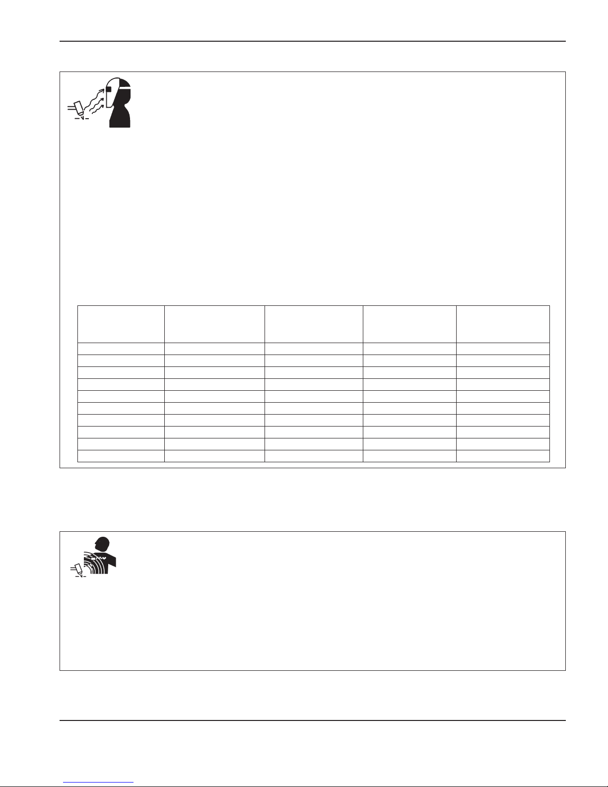
ARC RAYS CAN BURN EYES AND SKIN
Eye protection Plasma arc rays produce intense visible and invisible (ultraviolet and infrared) rays that can burneyes and skin.
• Use eye protection in accordance with applicable national and local codes.
• Wear eye protection (safety glasses or goggles with side shields, and a welding helmet) with appropriate lensshading to protect your eyes
from the arc’s ultraviolet and infrared rays.
Skin protection Wear protective clothing to protect against burns caused by ultraviolet light, sparks, and hotmetal.
• Gauntlet gloves, safety shoes and hat.
• Flame-retardant clothing to cover all exposed areas.
• Cuff less trousers to prevent entry of sparks and slag.
• Remove any combustibles, such as a butane lighter or matches, from your pockets before cutting.
Cutting area Prepare the cutting area to reduce reflection and transmission of ultraviolet light:
• Paint walls and other surfaces with dark colors to reduce reflection.
• Use protective screens or barriers to protect others from flash and glare.
• Warn others not to watch the arc. Use placards orsigns.
Minimum protective
Arc current
(amps)
Less than 40 A 5 5 8 9
41 to 60 A 6 6 8 9
61 to 80 A 8 8 8 9
81 to 125 A 8 9 8 9
126 to 150 A 8 9 8 10
151 to 175 A 8 9 8 11
176 to 250 A 8 9 8 12
251 to 300 A 8 9 8 13
301 to 400 A 9 12 9 13
401 to 800 A 10 14 10 N/A
shade number
(ANSIZ49.1:2005)
Suggested shade
number for comfort
(ANSI Z49.1:2005)
OSHA 29CFR
1910.133(a)(5)
PACEMAKER AND HEARINGAID OPERATION
Pacemaker and hearing aid operation can be affected by magnetic
fields from high currents.
Pacemaker and hearing aid wearers should consult a doctor before
going near any plasma arc cutting and gouging operations.
To reduce magnetic field hazards:
• Keep both the work cable and the torch lead to one side, away from
your body.
• Route the torch leads as close as possible to the workcable.
• Do not wrap or drape the torch lead or work cable around your
body.
• Keep as far away from the power supply as possible.
Europe
EN 169:2002
S-5 Hypertherm Safety and Compliance
English
Page 14

NOISE CAN DAMAGE HEARING
SAFETY
Cutting with a plasma arc can exceed acceptable noise levels as
defined by local codes in many applications. Prolonged exposure
to excessive noise can damage hearing. Always wear proper ear
protection when cutting or gouging, unless sound pressure level
measurements taken at the installed site have verified personal hearing
protection is not necessary per relevant international, regional, and
local codes.
Significant noise reduction can be obtained by adding simple
engineering controls to cutting tables such as barriers or curtains
positioned between the plasma arc and the workstation; and/or
locating the workstation away from the plasma arc. Implement
DRY DUST COLLECTION INFORMATION
At some sites, dry dust can represent a potential explosion hazard.
The U.S. National Fire Protection Association’s 2007 edition of NFPA
standard 68, “Explosion Protection by Deflagration Venting,” provides
requirements for the design, location, installation, maintenance, and
use of devices and systems to vent combustion gases and pressures
after any deflagration event. Consult with the manufacturer or installer
of any dry dust collection system for applicable requirements before
you install a new dry dust collection system or make significant
changes in the process or materials used with an existing dry dust
collection system.
Consult your local “Authority Having Jurisdiction” (AHJ) to determine
whether any edition of NFPA 68 has been “adopted by reference” in
your local building codes.
Refer to NFPA68 for definitions and explanations of regulatory terms
such as deflagration, AHJ, adopted by reference, the Kst value,
deflagration index, and other terms.
administrative controls in the workplace to restrict access, limit
operator exposure time, screen off noisy working areas and/or take
measures to reduce reverberation in working areas by putting up noise
absorbers.
Use ear protectors if the noise is disruptive or if there is a risk of
hearing damage after all other engineering and administrative controls
have been implemented. If hearing protection is required, wear only
approved personal protective devices such as ear muffs or ear plugs
with a noise reduction rating appropriate for the situation. Warn others
in the area of possible noise hazards. In addition, ear protection can
prevent hot splatter from entering the ear.
Note 1 – Hypertherm’s interpretation of these new requirements is
that unless a site-specific evaluation has been completed to determine
that all dust generated is not combustible, the 2007 edition of NFPA
68 requires the use of explosion vents designed to the worst-case
Kst value (see annex F) that could be generated from dust so that
the explosion vent size and type can be designed. NFPA 68 does not
specifically identify plasma cutting or other thermal cutting processes
as requiring deflagration venting systems, but it does apply these new
requirements to all dry dust collection systems.
Note 2 – Users of Hypertherm manuals should consult and comply
with all applicable federal, state, and local laws and regulations.
Hypertherm does not, by the publication of any Hypertherm manual,
intend to urge action that is not in compliance with all applicable
regulations and standards, and this manual may never be construed
as doing so.
Hypertherm Safety and Compliance S-6
English
Page 15
SAFETY
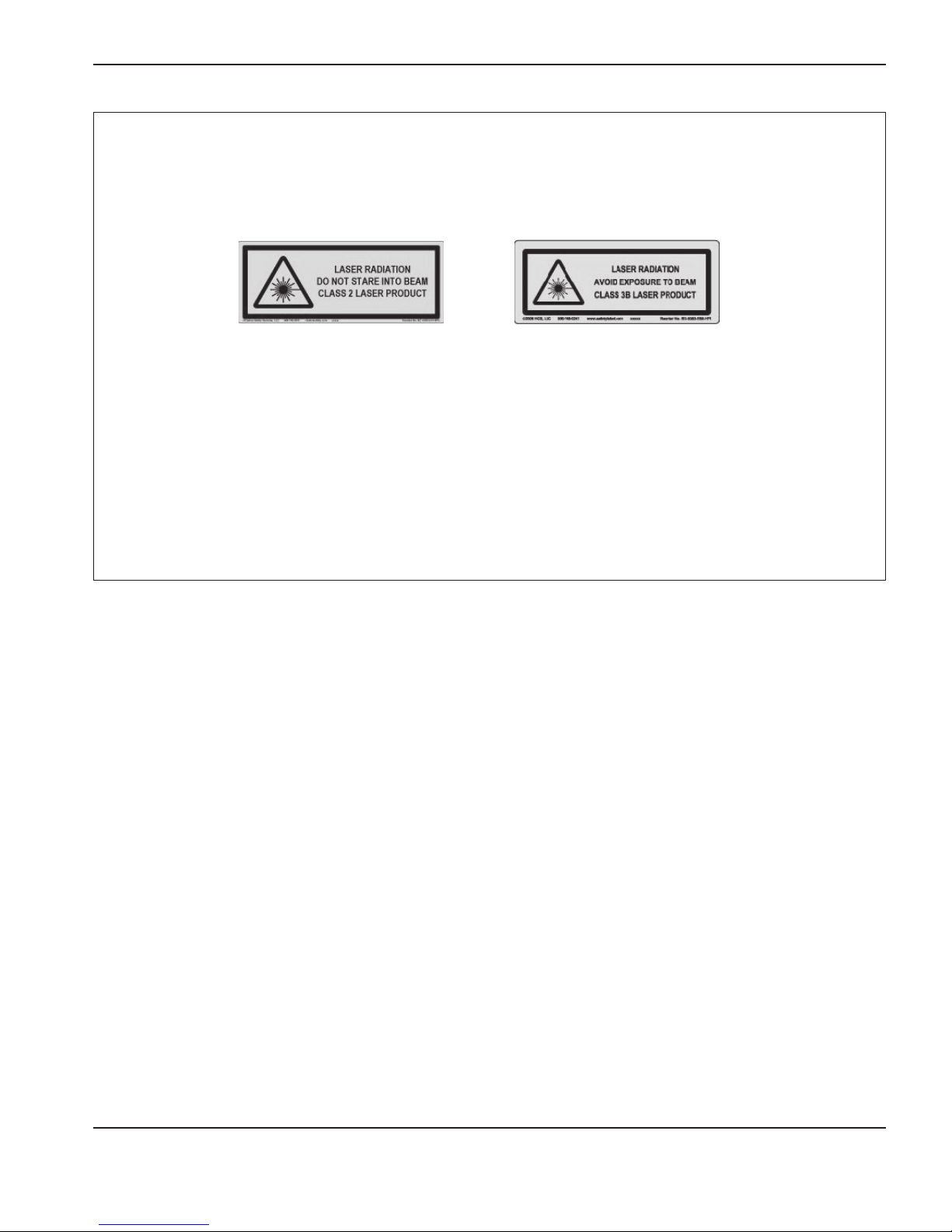
LASER RADIATION
Exposure to the laser output can result in serious eye injury. Avoid direct eye exposure.
For your convenience and safety, on Hypertherm products that use a laser, one of the following laser radiation labels has been applied on
the product near where the laser beam exits the enclosure. The maximum output (mV), wavelength emitted (nM) and, if appropriate, the pulse
duration is also provided.
Additional laser safety instructions:
• Consult with an expert on local laser regulations. Laser safety
training may be required.
• Do not allow untrained persons to operate the laser. Lasers can be
dangerous in the hands of untrained users.
• Do not look into the laser aperture or beam at any time.
• Position the laser as instructed to avoid unintentional eye contact.
• Do not use the laser on reflective workpieces.
• Do not use optical tools to view or reflect the laser beam.
• Do not disassemble or remove the laser or aperture cover.
• Modifying the laser or product in any way can increase the risk of
laser radiation.
• Use of adjustments or performance of procedures other than those
specified in this manual may result in hazardous laser radiation
exposure.
• Do not operate in explosive atmospheres, such as in the presence of
flammable liquids, gases, or dust.
• Use only laser parts and accessories that are recommended or
provided by the manufacturer for your model.
• Repairs and servicing MUST be performed by qualified personnel.
• Do not remove or deface the laser safety label.
ADDITIONAL SAFETY INFORMATION
1. ANSI Standard Z49.1, Safety in Welding and Cutting, American
Welding Society, 550 LeJeune Road
P.O. Box 351020, Miami, FL 33135
2. ANSI Standard Z49.2, Fire Prevention in the Use of Cutting and
Welding Processes, American National Standards Institute
1430 Broadway, New York, NY 10018
3. ANSI Standard Z87.1, Safe Practices for Occupation and
Educational Eye and Face Protection, American National Standards
Institute, 1430 Broadway, New York, NY 10018
4. AWS F4.1, Recommended Safe Practices for the Preparation for
Welding and Cutting of Containers and Piping That Have Held
Hazardous Substances, American Welding Society
550 LeJeune Road, P.O. Box 351040, Miami, FL 33135
5. AWS F5.2, Recommended Safe Practices for Plasma Arc
Cutting, American Welding Society
550 LeJeune Road, P.O. Box 351040, Miami, FL 33135
6. CGA Pamphlet P-1, Safe Handling of Compressed Gases in
Cylinders, Compressed Gas Association
1235 Jefferson Davis Highway, Arlington, VA 22202
7. CSA Standard W117.2, Code for Safety in Welding and Cutting,
Canadian Standards Association Standard Sales
178 Rexdale Boulevard, Rexdale, Ontario M9W 1R3, Canada
8. NFPA Standard 51B, Cutting and Welding Processes, National
Fire Protection Association
470 Atlantic Avenue, Boston, MA 02210
9. NFPA Standard 70–1978, National Electrical Code, National Fire
Protection Association, 470 Atlantic Avenue, Boston, MA 02210
10. OSHA, Safety and Health Standards, 29FR 1910
U.S. Government Printing Office, Washington, D.C. 20402
11. AWS Safety and Health Fact Sheets, American Welding Society 550
LeJeune Road, P.O. Box 351040, Miami, FL 33135
www.aws.org/technical/facts/
12. ASTM, D 4185-96(2001) E1, Practice for Measurement of
Metals in Workplace Atmosphere by Flame Atomic Absorption
Spectrophotometry, ASTM International, 100 Barr Harbor Drive, West
Conshohocken, Pennsylvania 19428
http://www.astm.org/
13. AS/NZS 3760:2003, In-service safety inspection and testing of
electrical equipment. Standards Australia, Level 10, The Exchange
Centre, 20 Bridge Street, Sydney, GPO Box 476, Sydney NSW 2001
http://www.standards.org.au
14. NFPA 68, Standard on Explosion Protection by Deflagration Venting,
National Fire Protection Association (NFPA), 1 Batterymarch Park
Quincy, Massachusetts 02169-7471
http://www.nfpa.org
15. CEN publication, EN 169:2002 Personal eye-protection - Filters for
welding and related techniques - Transmittance requirements and
recommended use. The European Committee for Standardization
(CEN), CEN-CENELEC Management Centre, Avenue Marnix 17,
B-1000 Brussels
http://www.cen.eu
S-7 Hypertherm Safety and Compliance
English
Page 16

Hypertherm Safety and Compliance S-8
English
Page 17

PRODUCT STEWARDSHIP
Introduction
Hypertherm maintains a global Regulatory Management System
to ensure that products comply with regulatory and environmental
requirements.
National and local safety regulations
National and Local safety regulations shall take precedence over any
instructions provided with the product. The product shall be imported,
installed, operated and disposed of in accordance with national and
local regulations applicable to the installed site.
Certification test marks
Certified products are identified by one or more certification test marks
from accredited testing laboratories. The certification test marks are
located on or near the data plate.
Each certification test mark means that the product and its safetycritical components conform to the relevant national safety standards
as reviewed and determined by that testing laboratory. Hypertherm
places a certification test mark on its products only after that product
is manufactured with safety-critical components that have been
authorized by the accredited testing laboratory.
Once the product has left the Hypertherm factory, the certification test
marks are invalidated if any of the following occurs:
• The product is modified in a manner that creates a hazard or non-
conformance with the applicable standards.
• Safety-critical components are replaced with unauthorized spare
parts.
• Any unauthorized assembly, or accessory that uses or generates a
hazardous voltage is added.
• There is any tampering with a safety circuit or other feature that is
designed into the product as part of the certification, or otherwise.
CE marking constitutes a manufacturer’s declaration of conformity to
applicable European directives and standards. Only those versions of
Hypertherm products with a CE Marking located on or near the data
plate have been tested for compliance with the European Low Voltage
Directive and the European EMC Directive. EMC filters needed to
comply with the European EMC Directive are incorporated within
versions of the power supply with a CE Marking.
Certificates of compliance for Hypertherm products are available from
the Downloads Library on the Hypertherm web site at
https://www.hypertherm.com.
Differences in national standards
Nations may apply different performance, safety or other standards.
National differences in standards include, but are not limited to:
• Voltages
• Plug and cord ratings
• Language requirements
• Electromagnetic compatibility requirements
These differences in national or other standards may make it
impossible or impractical for all certification test marks to be placed
on the same version of a product. For example, the CSA versions
of Hypertherm’s products do not comply with European EMC
requirements, and therefore do not have a CE marking on the data
plate.
Countries that require CE marking or have compulsory EMC
regulations must use CE versions of Hypertherm products with the CE
marking on the data plate. These include, but are not limited to:
• Australia
• New Zealand
• Countries in the European Union
• Russia
It is important that the product and its certification test mark be
suitable for the end-use installation site. When Hypertherm products
are shipped to one country for export to another country; the product
must be configured and certified properly for the end-use site.
Safe installation and use of shape
cutting equipment
IEC 60974-9, titled Arc Welding Equipment – Installation and
use, provides guidance in the safe installation and use of shape
cutting equipment and the safe performance of cutting operations.
The requirements of national and local regulations shall be taken
into consideration during installation, including, but not limited
to, grounding or protective earth connections, fuses, supply
disconnecting device, and type of supply circuit. Read these
instructions before installing the equipment. The first and most
important step is the safety assessment of the installation.
The safety assessment must be performed by an expert, and
determines what steps are necessary to create a safe environment,
and what precautions should be adopted during the actual installation
and operation.
Procedures for periodic inspection and
testing
Where required by local national regulations, IEC60974-4
specifies test procedures for periodic inspection and after repair or
maintenance, to ensure electrical safety for plasma cutting power
sources built in conformity with IEC 60974-1. Hypertherm performs
the continuity of the protective circuit and insulation resistance tests
in the factory as non-operating tests. The tests are performed with the
power and ground connections removed.
Hypertherm also removes some protective devices that would cause
false test results. Where required by local national regulations, a label
shall be attached to the equipment to indicate that it has passed the
tests prescribed by IEC60974-4. The repair report shall indicate the
results of all tests unless an indication is made that a particular test
has not been performed.
Hypertherm Safety and Compliance PS-1
English
Page 18

Product StewardShiP
Qualification of test personnel
Electrical safety tests for shape cutting equipment can be hazardous
and shall be carried out by an expert in the field of electrical repair,
preferably someone also familiar with welding, cutting, and allied
processes. The safety risks to personnel and equipment, when
unqualified personnel are performing these tests, may be much greater
than the benefit of periodic inspection and testing.
Hypertherm recommends that only visual inspection be performed
unless the electrical safety tests are specifically required by local
national regulations in the country where the equipment is installed.
Residual current devices (RCDs)
In Australia and some other countries, local codes may require the
use of a Residual Current Devices (RCD) when portable electrical
equipment is used in the workplace or at construction sites to protect
operators from electrical faults in the equipment. RCDs are designed
to safely disconnect the mains electrical supply when an imbalance
is detected between the supply and return current (there is a leakage
current to earth). RCDs are available with both fixed and adjustable
trip currents between 6to 40 milliamperes and a range of trip times
up to 300milliseconds selected for the equipment installation,
application and intended use. Where RCDs are used, the trip current
and trip time on RCDs should be selected or adjusted high enough
to avoid nuisance tripping during normal operation of the plasma
cutting equipment and low enough in the extremely unlikely event of
an electrical fault in the equipment to disconnect the supply before
the leakage current under a fault condition can pose a life threatening
electrical hazard to operators.
To verify that the RCDs continue to function properly over time, both
the trip current and the trip time should be tested periodically. Portable
electrical equipment and RCDs used in commercial and industrial
areas in Australia and New Zealand are tested to the Australian
standard AS/NZS3760. When you test the insulation of plasma
cutting equipment to AS/NZS 3760, measure the insulation resistance
according to Appendix B of the standard, at 250VDC with the power
switch in the ON position to verify proper testing and to avoid the false
failure of the leakage current test. False failures are possible because
the metal oxide varistors (MOVs) and electromagnetic compatibility
(EMC) filters, used to reduce emissions and protect the equipment
from power surges, may conduct up to 10milliamperes leakage
current to earth under normal conditions.
If you have any questions regarding the application or interpretation
of any IEC standards described here, you are required to consult with
an appropriate legal or other advisor familiar with the International
Electrotechnical standards, and shall not rely on Hypertherm in any
respect regarding the interpretation or application of such standards.
protection against hazardous moving parts. Unless the higherlevel system is certified when the OEM incorporates Hypertherm
products into it, the installation also may be subject to approval by
local authorities. Seek advice from legal counsel and local regulatory
experts if you are uncertain about compliance.
External interconnecting cables between component parts of the
higher level system must be suitable for contaminants and movement
as required by the final end use installation site. When the external
interconnecting cables are subject to oil, dust, water, or other
contaminants, hard usage ratings may be required.
When external interconnecting cables are subject to continuous
movement, constant flexing ratings may be required. It is the
responsibility of the end-use customer or the OEM to ensure the
cables are suitable for the application. Since there are differences
in the ratings and costs that can be required by local regulations
for higher level systems, it is necessary to verify that any external
interconnecting cables are suitable for the end-use installation site.
Higher-level systems
When a system integrator adds additional equipment; such as cutting
tables, motor drives, motion controllers or robots; to a Hypertherm
plasma cutting system, the combined system may be considered a
higher-level system. A higher-level system with hazardous moving
parts may constitute industrial machinery or robotic equipment,
in which case the OEM or end-use customer may be subject to
additional regulations and standards than those relevant to the plasma
cutting system as manufactured by Hypertherm.
It is the responsibility of the end-use customer and the OEM to
perform a risk assessment for the higher-level system, and to provide
PS-2 Hypertherm Safety and Compliance
English
Page 19

Introduction
The Hypertherm Environmental Specification requires RoHS, WEEE
and REACH substance information to be provided by Hypertherm’s
suppliers.
Product environmental compliance does not address the indoor
air quality or environmental release of fumes by the end user. Any
materials that are cut by the end user are not provided by Hypertherm
with the product. The end user is responsible for the materials being
cut as well as for safety and air quality in the workplace. The end user
must be aware of the potential health risks of the fumes released from
the materials being cut and comply with all local regulations.
National and local environmental
regulations
National and local environmental regulations shall take precedence
over any instructions contained in this manual.
The product shall be imported, installed, operated and disposed of
in accordance with all national and local environmental regulations
applicable to the installed site.
The European Environmental regulations are discussed later in The
WEEE Directive.
The RoHS directive
Hypertherm is committed to complying with all applicable laws and
regulations, including the European Union Restriction of Hazardous
Substances (RoHS) Directive that restricts the use of hazardous
materials in electronics products. Hypertherm exceeds RoHS Directive
compliance obligations on a global basis.
Hypertherm continues to work toward the reduction of RoHS materials
in our products, which are subject to the RoHS Directive, except
where it is widely recognized that there is no feasible alternative.
Declarations of RoHS Conformity have been prepared for the current
CE versions of Powermax plasma cutting systems manufactured
by Hypertherm. There is also a “RoHS mark” on the Powermax CE
versions below the “CE Marking” on the data plate of CE versions
of Powermax series units shipped since 2006. Parts used in
CSA versions of Powermax and other products manufactured by
Hypertherm that are either out of scope or exempt from RoHS are
continuously being converted to RoHS compliance in anticipation of
future requirements.
Proper disposal of Hypertherm products
Hypertherm plasma cutting systems, like all electronic products, may
contain materials or components, such as printed circuit boards,
that cannot be discarded with ordinary waste. It is your responsibility
to dispose of any Hypertherm product or component part in an
environmentally acceptable manner according to national and local
codes.
• In the United States, check all federal, state, and local laws.
ENVIRONMENTAL STEWARDSHIP
• In the European Union, check the EU directives, national, and local
laws. For more information, visit www.hypertherm.com/weee.
• In other countries, check national and local laws.
• Consult with legal or other compliance experts when appropriate.
The WEEE directive
On January 27, 2003, the European Parliament and the Council of the
European Union authorized Directive 2002/96/EC or WEEE (Waste
Electrical and Electronic Equipment).
As required by the legislation, any Hypertherm product covered by the
directive and sold in the EU after August 13, 2005 is marked with the
WEEE symbol. This directive encourages and sets specific criteria for
the collection, handling, and recycling of EEE waste. Consumer and
business-to-business wastes are treated differently (all Hypertherm
products are considered business-to-business). Disposal instructions
for the CE versions of Powermax plasma systems can be found at
www.hypertherm.com/weee.
The URL is printed on the symbol-only warning label for each of
these CE version Powermax series units shipped since 2006. The
CSA versions of Powermax and other products manufactured by
Hypertherm are either out of scope or exempt from WEEE.
The REACH regulation
The REACH regulation (1907/2006), in force since June1, 2007,
has an impact on chemicals available to the European market. The
REACH regulation requirements for component manufacturers states
that the component shall not contain more than 0.1% by weight of the
Substances of Very High Concern (SVHC).
Component manufacturers and other downstream users, such as
Hypertherm, are obligated to obtain assurances from its suppliers that
all chemicals used in or on Hypertherm products will have a European
Chemical Agency (ECHA) registration number. To provide chemical
information as required by the REACH regulation, Hypertherm requires
suppliers to provide REACH declarations and identify any known use
of REACH SVHC. Any use of SVHC in amounts exceeding 0.1% w/w
of the parts has been eliminated. The MSDS contains a full disclosure
of all substances in the chemical and can be used to verify REACH
SVHC compliance.
The lubricants, sealants, coolants, adhesives, solvents, coatings and
other preparations or mixtures used by Hypertherm in, on, for, or with
its shape cutting equipment are used in very small quantities (except
the coolant) and are commercially available with multiple sources that
can and will be replaced in the event of a supplier problem associated
with REACH Registration or REACH Authorization (SVHCs).
Proper handling and safe use of
chemicals
Chemical Regulations in the USA, Europe, and other locations
require that Material Safety Data Sheets (MSDS) be made available
for all chemicals. The list of chemicals is provided by Hypertherm.
Hypertherm Safety and Compliance eS-1
English
Page 20

environmental StewardShiP
The MSDS are for chemicals provided with the product and other
chemicals used in or on the product. MSDS can be downloaded from
the Downloads Library on the Hypertherm web site at https://www.
hypertherm.com. On the Search screen, insert MSDS in the document
title and click on Search.
In the USA, OSHA does not require Material Safety Data Sheets for
articles such as electrodes, swirl rings, retaining caps, nozzles, shields,
deflectors and other solid parts of the torch.
Hypertherm does not manufacture or provide the materials that are
cut and has no knowledge whether the fumes released from materials
that are cut will pose a physical hazard or health risk. Please consult
with your supplier or other technical advisor if you need guidance
concerning the properties of the material you will cut using a
Hypertherm product.
Fumes emission and air quality
Note: The following information on air quality is intended for general
information only and should not be used as a substitute for reviewing
and implementing applicable government regulations or legal
standards in the country where the cutting equipment will be installed
and operated.
In the USA, the National Institute for Occupational Safety and Health
(NIOSH) Manual of Analytical Methods (NMAM) is a collection of
methods for sampling and analyzing contaminants in workplace air.
Methods published by others, such as OSHA, MSHA, EPA, ASTM,
ISO or commercial suppliers of sampling and analytical equipment,
may have advantages over NIOSH methods.
For example, ASTM Practice D 4185 is a standard practice for the
collection, dissolution, and determination of trace metals in workplace
atmospheres. The sensitivity, detection limit, and optimum working
concentrations for 23 metals are listed in ASTMD4185. An industrial
hygienist should be used to determine the optimum sampling protocol,
considering analytical accuracy, cost, and optimum sample number.
Hypertherm uses a third party industrial hygienist to perform and
interpret air quality testing results taken by air sampling equipment
positioned at operator stations in Hypertherm buildings where plasma
cutting tables are installed and operated.
Where applicable, Hypertherm also uses a third party industrial
hygienist to obtain air and water permits.
If you are not fully aware and up to date on all applicable government
regulations and legal standards for the installation site, you should
consult a local expert prior to purchasing, installing, and operating the
equipment.
eS-2 Hypertherm Safety and Compliance
English
Page 21

Section 1
SPECIFICATIONS
In this section
Introduction .................................................................................................................................................................................................1-3
Control module ................................................................................................................................................................................1-3
Lifter assembly .................................................................................................................................................................................1-3
Human machine interface (HMI) ..................................................................................................................................................1-3
Plasma interface ..............................................................................................................................................................................1-4
Industrial Ethernet switch ..............................................................................................................................................................1-4
Specifications .............................................................................................................................................................................................1-5
System ...............................................................................................................................................................................................1-5
Control module (090054) .............................................................................................................................................................1-5
Lifter assembly (090053) ..............................................................................................................................................................1-6
Optional HMI (090055) .................................................................................................................................................................1-7
Discrete plasma interface (090052) ...........................................................................................................................................1-8
Ethernet switch ................................................................................................................................................................................1-9
ArcGlide communication ......................................................................................................................................................................1-11
Hypernet communication configurations ................................................................................................................................ 1-12
Discrete communication configurations .................................................................................................................................. 1-13
Mixed communication configurations ..................................................................................................................................... 1-13
ArcGlide THC Instruction Manual 1-1
2
Page 22
SPECIFICATIONS
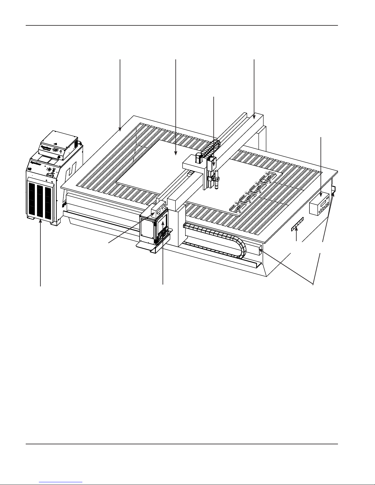
Cutting table GantryWorkpiece
ArcGlide lifter
ArcGlide control
module
Plasma system
Example of an ArcGlide THC installed on a cutting table with a plasma system and CNC
Note:
The ArcGlide control module and Ethernet switch should be located in an electrical cabinet that is
electrically grounded and environmentally clean.
ArcGlide HMI
(optional)
CNC
Star ground
Rails
1-2 ArcGlide THC Instruction Manual
Page 23

SPECIFICATIONS
Introduction
The Hypertherm ArcGlide THC is a voltage sensing, torch height control (THC) system that is designed for plasma
cutting applications on an X-Y cutting table. The system uses the plasma arc voltage to control the physical distance
between the torch and the workpiece during cutting. Up to 4 ArcGlide systems can be installed on a cutting table. The
system includes the following components, as shown in the illustration on the facing page:
Control module
The control module houses a microcontroller, I/O interface, and a motor drive. This unit provides arc voltage control,
and interfaces with the torch lifter, the CNC machine, and the plasma system through standard discrete I/O interfaces
through the Hypernet® interface.
Lifter assembly
The torch lifter station, under control of the control module, positions a torch head vertically above the workpiece.
The lifter has the following features:
• Ability to detect the workpiece using Ohmic contact sense circuitry or stall force
• Magnetic torch breakaway with circuitry to indicate a collision
• Lifter station enable and disable switch with an indicator light
• Manual up and down switch
• Laser pointer for work piece alignment
• Single interface cable
Human machine interface (HMI)
The HMI includes a liquid crystal display (LCD), operating switches, and a rotary/push knob selector for THC setup and
control. This module is optional when used with Hypertherm CNCs that can run Phoenix version 9.5 software (or later).
The main functions are:
• THC system and operational setup
• Entry for operating parameters
• Manual and automatic operation
• Initial height sense (IHS) test
• THC status and arc voltage display
• THC error display
• Multiple language support
• English or metric unit support
• Station enable and disable
ArcGlide THC Instruction Manual 1-3
Page 24

SPECIFICATIONS
Plasma interface
The plasma interface performs two main functions. It provides precise, scaled feedback of the plasma arc voltage to the
control module. It also provides a convenient control signal interface to the ArcGlide THC. Hypertherm offers two types
of plasma interface:
• HPR: Hypernet communication, factory installed
• All other plasma systems: discrete communication, field installed
Industrial Ethernet switch
An industrial grade Ethernet switch is required in configurations that have more than one span of Hypernet. For more
detailed requirements, refer to Ethernet switch in this section.
1-4 ArcGlide THC Instruction Manual
Page 25
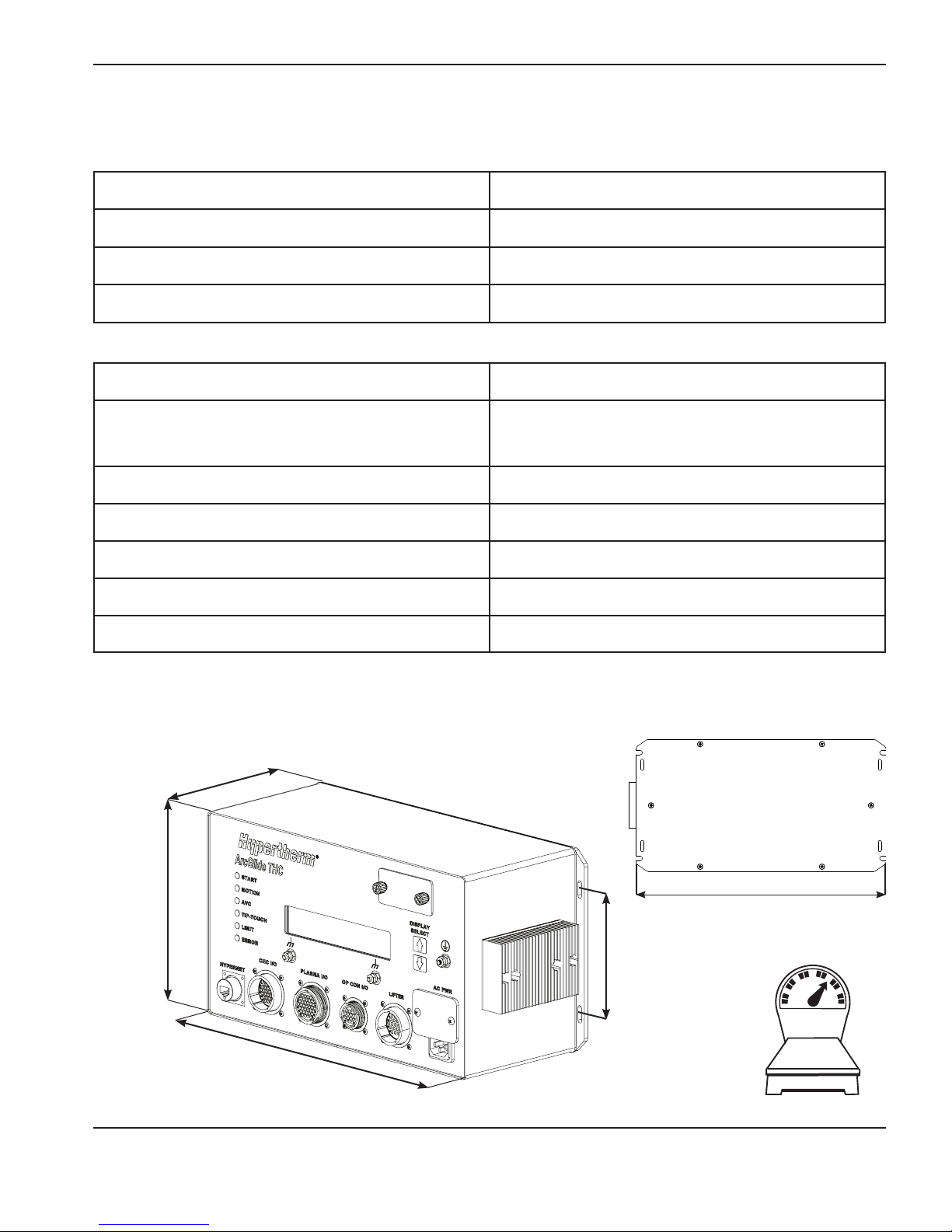
SPECIFICATIONS
Specifications
System
Input power 115 VAC or 230 VAC, 1 Phase, 50/60 Hz
Operating temperature -10º C to 40º C (14º F to 104º F)
Operating humidity 95% relative humidity
Warranty 2 years for electronics and lifter
Control module (090054)
Regulatory approvals CE, CSA
Fused input power (selectable)*
100 to 120 VAC/200 to 240 VAC, 2.6 A/1.5A,
50/60Hz, 1Phase,
Slow blow fuse 250 VAC, 5 A
Parallel digital input range +12 VDC to +24 VDC
Serial digital I/O +5 VDC (Plasma interface serial)
Maximum motor drive output 70 VDC, 6 A
Hypernet communication Shielded RJ-45 Cat-5e
* To prevent damage to equipment, use the input module switch on the front of the control module to select the input
voltage (115 V or 240 V) that will be used.
157.23 mm
(6.19”)
206.25 mm
(8.12”)
358.65 mm
(14.12”)
ArcGlide THC Instruction Manual 1-5
381.00 mm
(15.37”)
127.00 mm
(5.00”)
7.26 kg
(16.00 lb)
Control module
2
Page 26
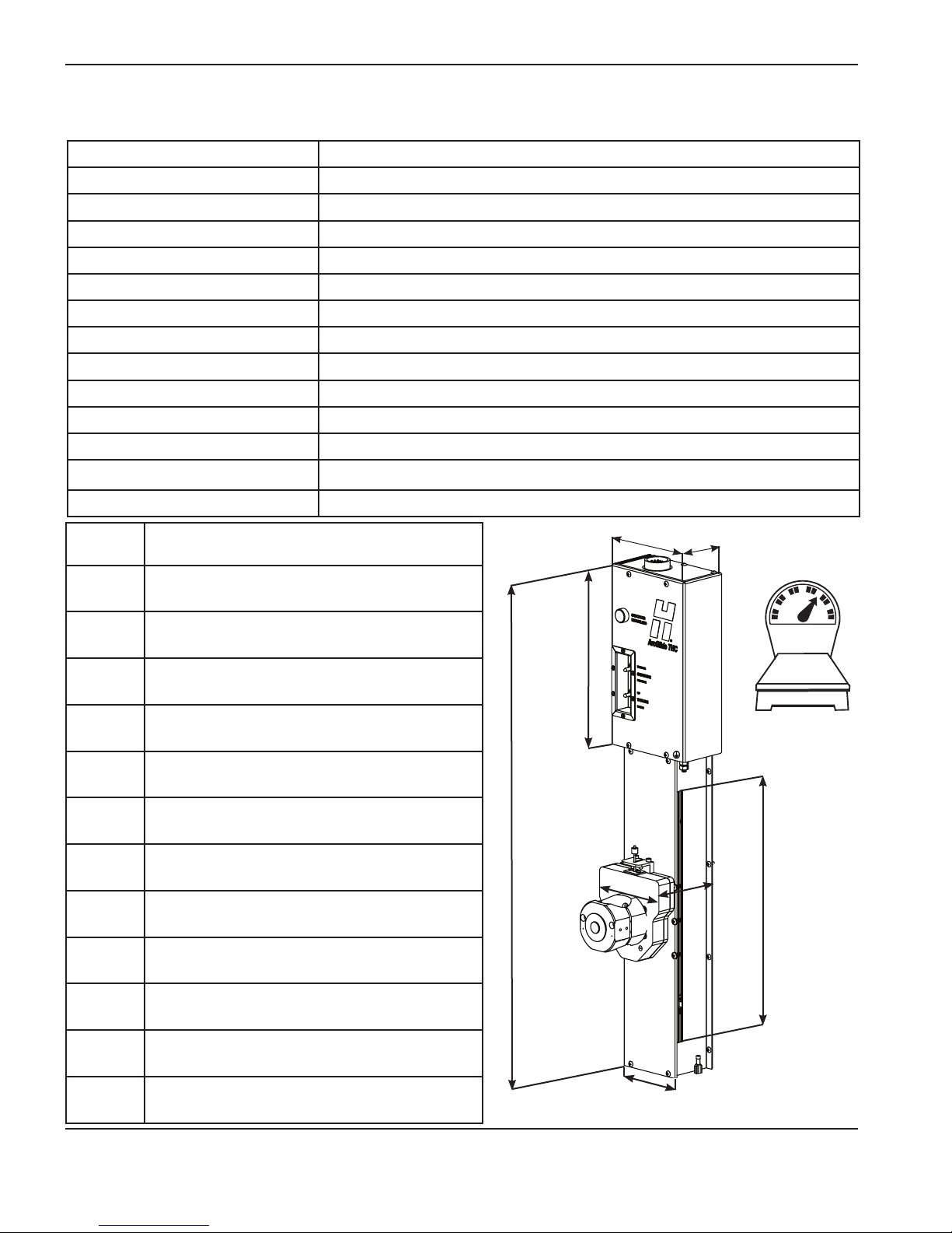
SPECIFICATIONS
Lifter assembly (090053)
Regulatory approvals CE
Motor 70 VDC, 3 A
Limit switches +24 VDC
Motor Permanent magnet
Motor drive PWM Servo amplifier
Lifter feedback Incremental encoder
Lifter limit switches Home switch and lower limit switch
Lifter control switches Manual up/down and station disable switches
Maximum Z axis speed 1520 cm/minute (600 in/minute)
Maximum Z axis stroke 239 mm (9.4 in)
Breakaway switch +24 VDC
Motor brake +24 VDC
Laser pointer (Class 3B) +5 VDC, Maximum power: 500 mW, Wavelength: 400 - 695 nm
Lifter capacity 11.3 kg (25.0 lb)
Part
Torch mounting and breakaway options
number
090082 51 mm (2 in) mounting, 11 kg (25 lb) magnetic
breakaway
090083 51 mm (2 in) mounting, pneumatic breakaway
090084 44 mm (1 3/4 in) mounting, pneumatic
breakaway
090085 35 mm (1 3/8 in) mounting, pneumatic
breakaway
090086 44 mm (1 3/4 in) mounting, 11 kg (25 lb)
magnetic breakaway
090087 35 mm (1 3/8 in) mounting, 11 kg (25 lb)
magnetic breakaway
090088 51 mm (2 in) mounting, 4.5 kg (10 lb) magnetic
breakaway
090089 44 mm (1 3/4 in) mounting, 4.5 kg (10 lb)
magnetic breakaway
090090 35 mm (1 3/8 in) mounting, 4.5 kg (10 lb)
magnetic breakaway
151.0 mm
268.1 mm
(10.6”)
743.2 mm
(29.3”)
50.8 mm
(5.9”)
(2.0”)
78.7 mm
(3.1”)
11.11 kg
(24.50 lb)
238.8 mm
(9.4”)
85.5 mm
(3.4”)
090091 Pneumatic breakaway
090092 4.5 kg (10 lb) magnetic breakaway
090093 11 kg (25 lb) magnetic breakaway
1-6 ArcGlide THC Instruction Manual
2
127.0 mm (5.0”)
Lifter assembly
Page 27
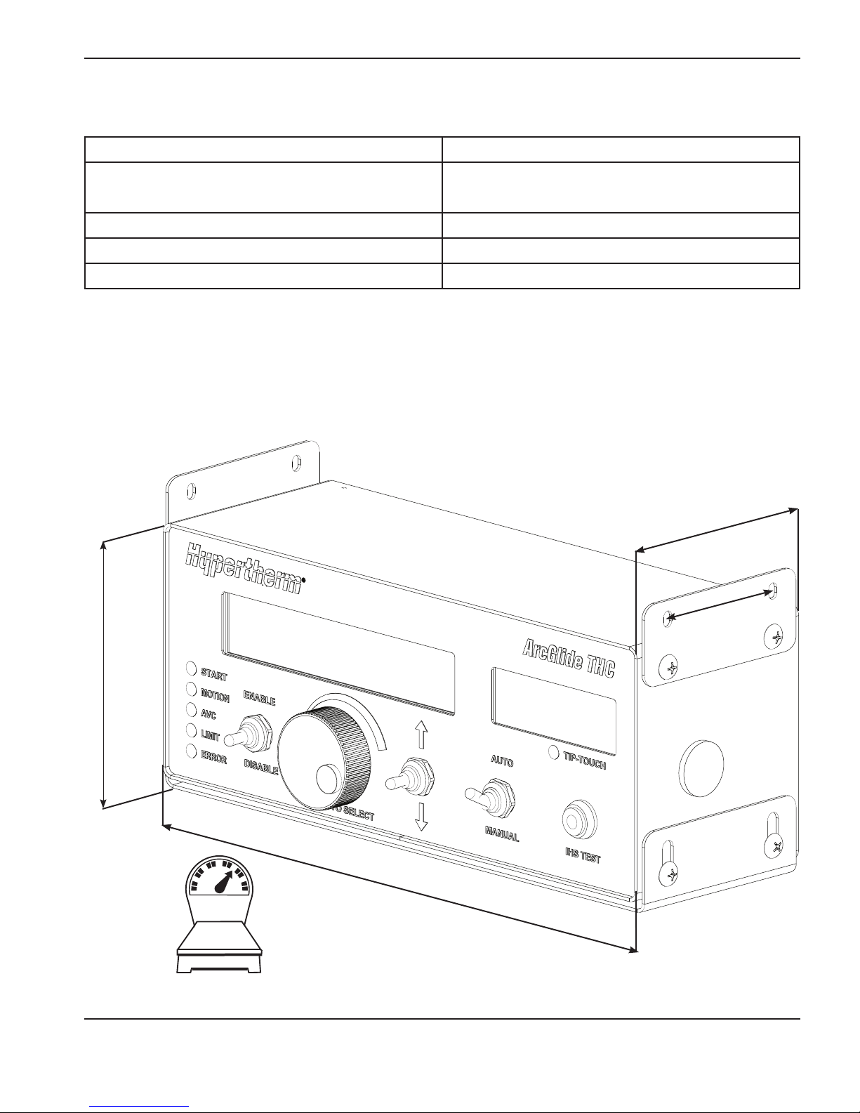
Optional HMI (090055)
Regulatory approvals CE, CSA
SPECIFICATIONS
Input power
100 VAC to 240 VAC, 50/60 Hz, 40 mA to 20mA,
1Phase,
Hypernet communication Shielded RJ-45 Cat-5e
Operating temperature -10º C to 40º C (14º F to 104º F)
Operating humidity 95% relative humidity
130.50 mm
(5.14”)
117.60
mm
(4.63”)
65.00 mm
(2.50”)
298.00 mm
(11.73”)
1.91 kg
(4.20 lb)
HMI
ArcGlide THC Instruction Manual 1-7
2
Page 28
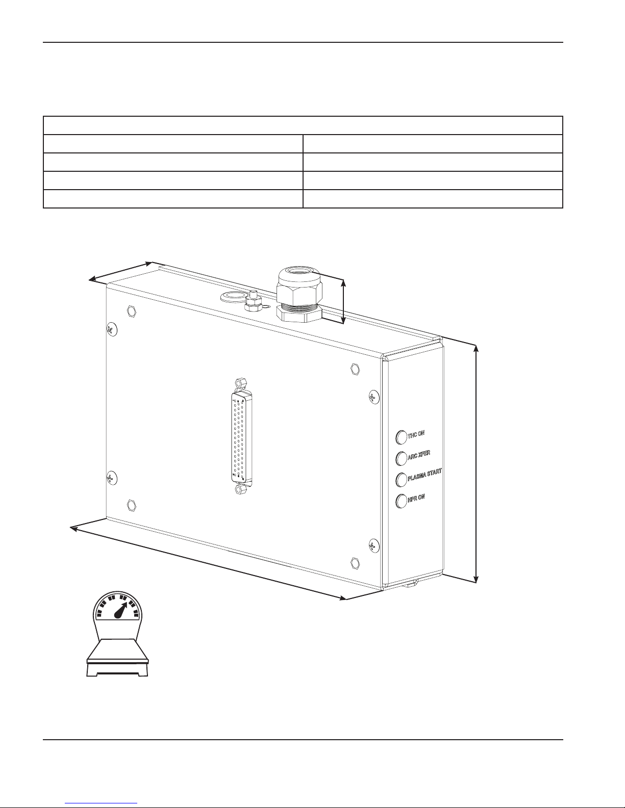
SPECIFICATIONS
Discrete plasma interface (090052)
This plasma interface is required for configurations that use discrete communication.
Electrical
Input power 24 V (AC or DC)
Parallel digital I/O +12 VDC to +24 VDC
Serial digital I/O 5 VDC
Voltage divider ratio 50:1 Arc voltage
50.80 mm
(2.00”)
27.69 mm
(1.09”)
145.29 mm
(5.72”)
127.00 mm
5.00”
0.68 kg
(1.5 lb)
Discrete plasma interface
1-8 ArcGlide THC Instruction Manual
2
Page 29

SPECIFICATIONS
Ethernet switch
If your ArcGlide THC uses more than one span of Hypernet to communicate with either the CNC or the plasma system,
you must include an Ethernet switch in the system configuration for communication between these components.
Notes: This switch must be an industrial grade switch that supports shielded Cat-5e Ethernet cable.
The Ethernet switch should be located in an electrical cabinet that is electrically grounded and
environmentally clean.
Hypertherm recommends three Advantech™ unmanaged industrial Ethernet switches, which are also available from
Hypertherm. The following page provides part numbers and details about each model.
A plasma arc cutting system can be configured with 1 CNC, up to 4 plasma systems, 4 THC controllers, 4 lifters, and 4
optional HMIs. The total number of ports your system requires depends on the number of power supplies and ArcGlide
THCs that are configured. Use the following table to help determine the number of Ethernet ports your system needs.
For each of these components: You need this many Ethernet ports:
CNC 1
Plasma system (1 to 4) + lifter (1 to 4) 2 to 8
Plasma system (1 to 4) + lifter (1 to 4) + HMI (1 to 4) 3 to 12
Total 4 to 13
For example, a cutting system with 2 power supplies + 2 THCs + 2 HMIs + 1 CNC = 7 ports.
Note: Hypernet connections and Ethernet connection to a LAN cannot be made through the same switch. If your
cutting system is connected to a LAN over Ethernet, you must use a separate Ethernet switch for these
connections.
ArcGlide THC Instruction Manual 1-9
2
Page 30
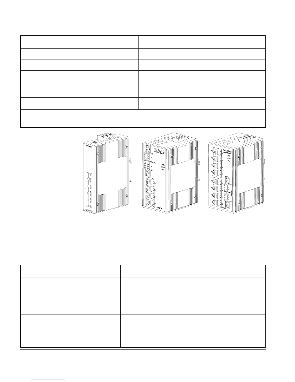
SPECIFICATIONS
5 Ports 8 Ports 16 Ports
Hypertherm part number 005657 005655 005656
Advantech part number EKI-2525I-AE EKI-7629C-AE EKI-7626C-AE
Width x height x depth
Maximum power
consumption
Power input (not
included)
The following table lists the operating specifications for the recommended Advantech Ethernet switches. Refer to the
respective Advantech user manuals for detailed and current information about installing and operating these switches.
37 mm x 140 mm x 95mm
(1.46 in x 5.51 in x 3.74in)
5 W 6.5 W 6.5 W
12 - 48 VDC redundant dual inputs with twisted pair cable.
79 mm x 152 mm x 105mm
(3.11 in x 5.98 in x 4.13in)
79 mm x 152 mm x 105mm
(3.11 in x 5.98 in x 4.13in)
If your cutting system does not include one of these Advantech Ethernet switches, use the specifications in the following
table to select an industrial-grade Ethernet switch that will support your plasma cutting system.
Ethernet connectors Shielded RJ-45e ports
Electrical protection
I/O transmission distance
I/O transmission speed 10/100 Mbps auto-negotiation
Operating temperature -10º C to 60º C (14º F to 140º F)
4000 VDC Ethernet ESD protection, 3000 VDC surge (EFT)
protection for the power line
Up to 100 m (109 yd) (4-wire Cat-5e)
1-10 ArcGlide THC Instruction Manual
Page 31

SPECIFICATIONS
ArcGlide communication
The diagrams on the next two pages illustrate discrete and Hypernet communication that the ArcGlide THC uses to
exchange signals with the CNC and the plasma system. Use the following table to distinguish between discrete and
Hypernet communication.
Communication style Data architecture Cabling configuration
Discrete
Hypernet Ethernet data packets
Note that both communication styles transmit the same signals. The difference is in the way the signals are “packaged”
for transmission over the two cabling configurations.
Notes Do not use redundant (both discrete and Hypernet) communication between the same two components in
the same ArcGlide configuration.
Discrete I/O and serial
data
A dedicated cable to each component from the ArcGlide control
module; within each cable, there is a dedicated wire for each signal
A standard, Cat-5e, shielded Ethernet cable from the Ethernet
switch to each component of the cutting system
ArcGlide THC Instruction Manual 1-11
2
Page 32

SPECIFICATIONS
Hypernet communication configurations
ArcGlide THCs in Hypernet configurations connect to the CNC and plasma system using the Hypernet protocol over
shielded, Ethernet Cat-5e cables. Both the CNC and plasma systems in this configuration must have a dedicated, Hypernetconfigured, Ethernet port for these connections.
In addition, a Hypernet configuration must include an industrial-grade Ethernet switch to route communication from the CNC
to the other units in the system.
Note: Each ArcGlide THC component (HMI, control module, and plasma interface) that is connected to the Hypernet
must have the same Hypernet unit address. This address must correspond to the station number for the THC
that is selected in Phoenix, on the Station setup screen. For more information, see Assign ArcGlide THC ports
in Section 3 Installation.
EDGE Pro HyPath
CNC
Key
Hypernet connection
Discrete connection
Hypernet address: 1
HMI
HMI
Hypernet address: 2
Lifter
ArcGlide control
module
Hypernet address: 1
Ethernet switch
Hypernet address: 2
ArcGlide control
module
Lifter
Station 1
HPR plasma system
with Hypernet
Plasma interface PCB
Hypernet address: 1
Hypernet address: 2
Plasma interface PCB
HPR plasma system
with Hypernet
Station 2
Basic configuration with Hypernet connections
There is no serial port on the ArcGlide THC. In a Hypernet configuration, serial signals are carried on the Hypernet cable
between the CNC and the ArcGlide THC and the ArcGlide plasma interface. Serial communication is carried between
the ArcGlide plasma interface and the plasma control board by a serial cable (123760).
CNC
Hypernet
Cat-5e
1-12 ArcGlide THC Instruction Manual
2
ArcGlide
THC
Hypernet
Cat-5e
ArcGlide plasma
interface
Plasma control
board
RS-422
Page 33

SPECIFICATIONS
Discrete communication configurations
In a discrete configuration, signals are routed through the ArcGlide control module. Each unit in the configuration,
except the HMI, is connected to the control module with discrete cables. The HMI communicates with the control
module using the Hypernet protocol over a shielded Ethernet Cat-5e cable. In a discrete configuration, the HMI must be
included.
Lifter
Plasma system
MicroEDGE Picopath
CNC
Key
Hypernet connection
Discrete connection
ArcGlide control
module
Plasma interface PCB
HMI
Basic configuration with discrete connections
Mixed communication configurations
In a mixed configuration, Hypernet communication is used between the ArcGlide THC and CNC or plasma system and
discrete communication is used for the alternate link from the ArcGlide THC. Whenever the HMI is used, it must be
connected to the control module with a Hypernet connection. See the following illustrations for details.
Hypernet-capable CNC
Hypernet connection
Discrete connection
CNC
Key
Lifter
ArcGlide control module
HMI
Lifter
ArcGlide control module
Plasma system
Plasma interface PCB
Plasma interface PCB
ArcGlide THC Instruction Manual 1-13
HMI
Basic configuration with mixed connections
Plasma system
2
Page 34

SPECIFICATIONS
1-14 ArcGlide THC Instruction Manual
Page 35

Section 2
INSTALLATION
In this section:
Hardware setup ..........................................................................................................................................................................................2-3
Upon receipt .....................................................................................................................................................................................2-3
Claims ................................................................................................................................................................................................2-3
Installation requirements ................................................................................................................................................................2-3
Placement of system components ..............................................................................................................................................2-3
Recommended grounding and shielding practices ...........................................................................................................................2-4
Introduction .................................................................................................................................................................................................2-4
Types of grounding .........................................................................................................................................................................2-4
Steps to take ....................................................................................................................................................................................2-5
RFI and EMI Grounding .................................................................................................................................................................2-9
System description for a Hypernet configuration ............................................................................................................................ 2-10
System description for a discrete configuration ..............................................................................................................................2-11
Configuration examples ......................................................................................................................................................................... 2-13
Multiple ArcGlide THCs with Hypernet connection to an EDGE Pro CNC and HPR or HPRXD
plasma system ...............................................................................................................................................................................2-13
ArcGlide THC with Hypernet connection to an EDGE Pro CNC and discrete connection to an HPR
or HPRXD plasma system .........................................................................................................................................................2-14
ArcGlide THC with discrete connection to a Picopath CNC and HPR or HPRXD plasma system ....................... 2-15
ArcGlide THC with discrete connection to a generic CNC and HPR or HPRXD plasma system ..........................2-16
ArcGlide THC with discrete connection to a generic CNC and HPR400XD .............................................................. 2-17
ArcGlide plasma interface with discrete connection to an HPR or HPRXD plasma system .................................... 2-18
ArcGlide THC with discrete communication to Picopath CNC and HSD130 plasma system .................................2-19
ArcGlide THC with discrete connections to Picopath CNC and MAX200, HT2000, or HT2000LHF
plasma system ...............................................................................................................................................................................2-20
ArcGlide plasma interface with discrete connection to MAX200, HT2000, or HT2000LHF plasma system ...... 2-21
ArcGlide plasma interface connection to Powermax G3 series plasma system ........................................................... 2-22
ArcGlide CNC interface with discrete connection to a Picopath CNC .......................................................................... 2-23
ArcGlide plasma interface discrete connection to any plasma system ...........................................................................2-24
ArcGlide THC Instruction Manual 2-1
Page 36

Install the lifter ..........................................................................................................................................................................................2-25
Connect the Ohmic wire to HPR XD plasma systems ........................................................................................................2-27
Connect the Ohmic wire to other plasma systems .............................................................................................................. 2-28
Ground the lifter ............................................................................................................................................................................2-29
Install the control module ......................................................................................................................................................................2-30
Ground the control module .......................................................................................................................................................2-31
Install the optional HMI ..........................................................................................................................................................................2-32
Ground the HMI ............................................................................................................................................................................ 2-33
Connect Hypernet cables ..................................................................................................................................................................... 2-34
Connect discrete cables ....................................................................................................................................................................... 2-36
Cables ....................................................................................................................................................................................................... 2-38
Lifter interface cable ...................................................................................................................................................................2-38
Hypernet and HMI interface cable ............................................................................................................................................2-39
Operator console I/O cable .......................................................................................................................................................2-40
ArcGlide motor control CNC interlock kit (228594) ........................................................................................................... 2-41
CNC I/O cable .............................................................................................................................................................................. 2-42
Plasma interface I/O cable ......................................................................................................................................................... 2-44
Non-serial plasma interface cable ............................................................................................................................................2-46
Serial plasma interface cable .....................................................................................................................................................2-48
ArcGlide discrete interface signal examples .................................................................................................................................... 2-49
Inputs ...............................................................................................................................................................................................2-49
Outputs ........................................................................................................................................................................................... 2-50
CNC discrete I/O .........................................................................................................................................................................2-51
Plasma discrete I/O ..................................................................................................................................................................... 2-53
Optional operator console discrete I/O .................................................................................................................................. 2-55
ArcGlide software setup ....................................................................................................................................................................... 2-56
ArcGlide axes ................................................................................................................................................................................2-57
ArcGlide THC ports .....................................................................................................................................................................2-58
ArcGlide setup parameters ........................................................................................................................................................ 2-59
ArcGlide THC Instruction Manual 2-2
Page 37

Section 2
INSTALLATION
In this section:
Hardware setup ..........................................................................................................................................................................................2-3
Upon receipt .....................................................................................................................................................................................2-3
Claims ................................................................................................................................................................................................2-3
Installation requirements ................................................................................................................................................................2-3
Placement of system components ..............................................................................................................................................2-3
Recommended grounding and shielding practices ...........................................................................................................................2-4
Introduction .................................................................................................................................................................................................2-4
Types of grounding .........................................................................................................................................................................2-4
Steps to take ....................................................................................................................................................................................2-5
RFI and EMI Grounding .................................................................................................................................................................2-9
System description for a Hypernet configuration ............................................................................................................................ 2-10
System description for a discrete configuration ..............................................................................................................................2-11
Configuration examples ......................................................................................................................................................................... 2-13
Multiple ArcGlide THCs with Hypernet connection to an EDGE Pro CNC and HPR or HPRXD
plasma system ...............................................................................................................................................................................2-13
ArcGlide THC with Hypernet connection to an EDGE Pro CNC and discrete connection to an HPR
or HPRXD plasma system .........................................................................................................................................................2-14
ArcGlide THC with discrete connection to a Picopath CNC and HPR or HPRXD plasma system ....................... 2-15
ArcGlide THC with discrete connection to a generic CNC and HPR or HPRXD plasma system ..........................2-16
ArcGlide THC with discrete connection to a generic CNC and HPR400XD .............................................................. 2-17
ArcGlide plasma interface with discrete connection to an HPR or HPRXD plasma system .................................... 2-18
ArcGlide THC with discrete communication to Picopath CNC and HSD130 plasma system .................................2-19
ArcGlide THC with discrete connections to Picopath CNC and MAX200, HT2000, or HT2000LHF
plasma system ...............................................................................................................................................................................2-20
ArcGlide plasma interface with discrete connection to MAX200, HT2000, or HT2000LHF plasma system ...... 2-21
ArcGlide plasma interface connection to Powermax G3 series plasma system ........................................................... 2-22
ArcGlide CNC interface with discrete connection to a Picopath CNC .......................................................................... 2-23
ArcGlide plasma interface discrete connection to any plasma system ...........................................................................2-24
ArcGlide THC Instruction Manual 2-1
Page 38

Install the lifter ..........................................................................................................................................................................................2-25
Connect the Ohmic wire to HPR XD plasma systems ........................................................................................................2-27
Connect the Ohmic wire to other plasma systems .............................................................................................................. 2-28
Ground the lifter ............................................................................................................................................................................2-29
Install the control module ......................................................................................................................................................................2-30
Ground the control module .......................................................................................................................................................2-31
Install the optional HMI ..........................................................................................................................................................................2-32
Ground the HMI ............................................................................................................................................................................ 2-33
Connect Hypernet cables ..................................................................................................................................................................... 2-34
Connect discrete cables ....................................................................................................................................................................... 2-36
Cables ....................................................................................................................................................................................................... 2-38
Lifter interface cable ...................................................................................................................................................................2-38
Hypernet and HMI interface cable ............................................................................................................................................2-39
Operator console I/O cable .......................................................................................................................................................2-40
ArcGlide motor control CNC interlock kit (228594) ........................................................................................................... 2-41
CNC I/O cable .............................................................................................................................................................................. 2-42
Plasma interface I/O cable ......................................................................................................................................................... 2-44
Non-serial plasma interface cable ............................................................................................................................................2-46
Serial plasma interface cable .....................................................................................................................................................2-48
ArcGlide discrete interface signal examples .................................................................................................................................... 2-49
Inputs ...............................................................................................................................................................................................2-49
Outputs ........................................................................................................................................................................................... 2-50
CNC discrete I/O .........................................................................................................................................................................2-51
Plasma discrete I/O ..................................................................................................................................................................... 2-53
Optional operator console discrete I/O .................................................................................................................................. 2-55
ArcGlide software setup ....................................................................................................................................................................... 2-56
ArcGlide axes ................................................................................................................................................................................2-57
ArcGlide THC ports .....................................................................................................................................................................2-58
ArcGlide setup parameters ........................................................................................................................................................ 2-59
ArcGlide THC Instruction Manual 2-2
Page 39

INSTALLATION
Hardware setup
Upon receipt
• Verify that all system components on your order have been received. Contact your supplier if any items aremissing.
• Inspect the system components for any physical damage that may have occurred during shipping. If there is evidence
of damage, refer to Claims. All communications regarding claims must include the model number and serial number
located on the back of the unit.
Claims
Claims for damage during shipment – If your unit was damaged during shipment, you must le a claim with the
carrier. Hypertherm will furnish you with a copy of the bill of lading upon request. If you need additional assistance, call
Customer Service listed in the front of this manual, or your authorized Hypertherm distributor.
Claims for defective or missing merchandise – If any of the merchandise is defective or missing, contact your
supplier. If you need additional assistance, call Customer Service listed in the front of this manual, or your authorized
Hypertherm distributor.
Installation requirements
All installation and service of the electrical and plumbing systems must conform to national and local
electrical and plumbing codes. This work should be performed only by qualified, licensed personnel.
Direct any technical questions to the nearest Hypertherm Technical Service Department listed in the front of this manual,
or your authorized Hypertherm distributor.
Placement of system components
• Place all system components in position prior to making electrical and interface connections. Use the diagram in this
section for component-placement guidelines.
• Ground all system components to earth. See Recommended grounding and shielding practices in this section for
details.
ArcGlide THC Instruction Manual 2-3
Page 40

INSTALLATION
Recommended grounding and shielding practices
DANGER
ELECTRIC SHOCK CAN KILL
Disconnect electrical power before performing any maintenance. All work
requiring the removal of the plasma system cover must be performed by a
qualified technician.
See Section 1 of the plasma system instruction manual for more safety
precautions.
Introduction
This document describes the grounding and shielding necessary to protect a plasma cutting system installation against
radio frequency interference (RFI) and electromagnetic interference (EMI) noise. It addresses the three grounding
systems described below. See the diagram in RFI and EMI grounding for details.
Note: These procedures and practices are not known to succeed in every case to eliminate RFI/EMI noise
issues. The practices listed here have been used on many installations with excellent results, and we
recommend that these practices be a routine part of the installation process. Theactual methods
used to implement these practices may vary from system to system, but should remain as consistent
as possible across the product line.
Types of grounding
A. The safety, protective earth (PE), or service ground. This is the grounding system that applies to the incoming line
voltage. It prevents a shock hazard to any personnel from any of the equipment, or the work table. It includes the
service ground coming into the plasma system and other systems such as the CNC controller and the motor drivers,
as well as the supplemental ground rod connected to the work table. In the plasma circuits, the ground is carried
from the plasma system chassis to the chassis of each separate console through the interconnecting cables.
B. The DC power or cutting current ground. This is the grounding system that completes the path of the cutting
current from the torch back to the plasma system. It requires that the positive lead from the plasma system be firmly
connected to the work table ground bus with a properly sized cable. It also requires that the slats, on which the
workpiece rests, make good contact with the table and the workpiece.
C. RFI and EMI grounding and shielding. This is the grounding system that limits the amount of electrical “noise”
emitted by the plasma and motor drive systems. It also limits the amount of noise that is received by the CNC and
other control and measurement circuits. This grounding/shielding process is the main target of this document.
2-4 ArcGlide THC Instruction Manual
Page 41

INSTALLATION
Steps to take
1. Unless noted, use only 6 AWG (16 mm2) welding cable (Hypertherm part no. 047040) for the EMI ground cables
shown on the diagram.
2. The cutting table is used for the common, or star, EMI ground point and should have threaded studs welded to the
table with a copper bus bar mounted on them. A separate bus bar should be mounted on the gantry as close to
each drive motor as possible. If there are drive motors at each end of the gantry, run a separate EMI ground cable
from the far drive motor to the gantry bus bar. The gantry bus bar should have a separate, heavy 21.2mm2 (4 AWG)
EMI ground cable (Hypertherm part number 047031) to the table bus bar. The EMI ground cables for the torch lifter
and the RHF console must each run separately to the table ground bus.
3. A ground rod that meets all applicable local and national electrical codes must be installed within 6 m (20 ft) of
thetable. This is a PE ground and should be connected to the ground bus on the cutting table with 16mm2 (6
AWG) green/yellow grounding cable (Hypertherm part number 047121) or equivalent.
4. For the most effective shielding, use the Hypertherm CNC interface cables for I/O signals, serial communication
signals, plasma system-to-plasma system multi-drop connections, and interconnections between all parts of the
Hypertherm system.
5. All hardware used in the ground system must be brass or copper. The only exception is that the studs welded to the
table for mounting the ground bus can be steel. Under no circumstances should aluminum or steel hardware be used.
6. AC power, PE, and service grounds must be connected to all equipment according to local and national codes.
7. * The positive, negative, and pilot arc leads should be bundled together for as long a distance as possible.
Thetorchlead, work lead, and the pilot arc (nozzle) leads may only be run parallel to other wires or cables if they
areseparated by at least 150 mm (6 in). If possible, run power and signal cables in separate cable tracks.
8. * The ignition console should be mounted as close as possible to the torch, and must have a separate ground cable
to the bus bar on the cutting table.
9. Each Hypertherm component, as well as any other CNC or motor-drive cabinet or enclosure, must have a separate
ground cable to the common (star) point on the table. This includes the ignition console, even if it is bolted to the
plasma system or to the cutting machine.
10. The metal braided shield on the torch leads must be connected firmly to the ignition console and to the torch.
Itmust be electrically insulated from any metal and from any contact with the floor or building. The leads can be
runin a plastic cable tray (track) or covered with a plastic or leather sheath.
11. The torch holder and the torch breakaway mechanism – the part mounted to the lifter, not the part mounted on
thetorch – must be connected to the stationary part of the lifter with copper braid at least 12.7 mm (1/2 in) wide.
Aseparate cable must run from the lifter to the bus bar on the gantry. The valve assembly should also have a
separate ground connection to the gantry bus bar.
* Applies to systems that use a remote high frequency (RHF) console
ArcGlide THC Instruction Manual 2-5
Page 42

INSTALLATION
12. If the gantry runs on rails that are not welded to the table, then the rails need to be connected with a ground cable
from each end of both rails to the table. These need not go to the common (star) point, but could take the shortest
path to the table.
13. If the OEM is installing a voltage divider to process arc voltage for use in the control system, the voltage divider
board should be mounted as close as possible to the point where the arc voltage is sampled. If the Hypertherm
voltage divider board is used, the output signal is isolated from all other circuits. The processed signal should be
run in twisted, shielded cable (Belden type 1800F or equivalent). The cable used must have a braided shield, not a
foil shield. The shield should be connected to the chassis of the plasma system and left unconnected at the other
end.
14. All other signals (analog, digital, serial, encoder) should run in twisted pairs inside a shielded cable. Connectors on
these cables should have a metal housing and the shield, not the drain, should be connected to the metal housing
of the connectors at each end of the cable. Never run the shield or the drain through the connector on any of the
pins.
2-6 ArcGlide THC Instruction Manual
Page 43

Gantry
Ground rod
INSTALLATION
Plasma
system lead
(+)
Example of a good cutting table ground bus.
The picture above shows the connection from the gantry ground bus, the connection from the ground rod, the plasma
system positive lead, the RHF console*, the CNC enclosure, the torch holder, and the plasma system chassis.
* Applies to systems that use a remote high frequency (RHF) console
ArcGlide THC Instruction Manual 2-7
Page 44

INSTALLATION
Cable to ground
bus on the cutting
table
Component
ground cables
Example of a good gantry ground bus.
It is bolted to the gantry, close to the motor. All of the individual ground cables from the components
mounted on the gantry go to the bus except those from the RHF console* and the torch holder. A
single heavy cable then goes from the gantry ground bus to the ground bus bolted to the table.
* Applies to systems that use a remote high frequency (RHF) console
2-8 ArcGlide THC Instruction Manual
Page 45
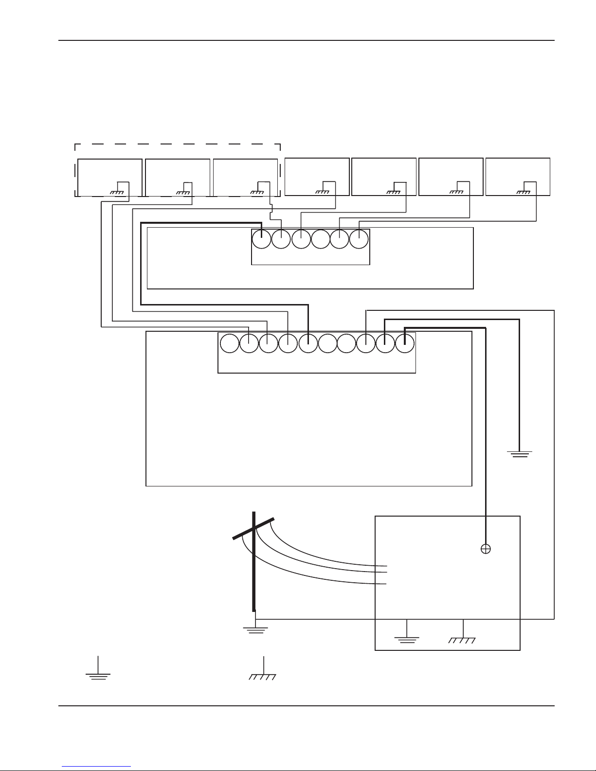
INSTALLATION
RFI and EMI Grounding
RFI and EMI grounding and shielding is the grounding system that limits the amount of electrical “noise” emitted by the
plasma and motor drive systems. It also limits the amount of noise that is received by the CNC and other control and
measurement circuits.
ArcGlide
Control
module
Lifter* HMI
RHF console* Metering
console
Bus bar
Gantry
Gas selection
console
CNC console
* The lifter and RHF console each
require a separate path to the cutting
table bus bar.
Bus bar
Cutting table
Driven
ground
Positive DC
Plasma system
AC earth or service ground
ArcGlide THC Instruction Manual 2-9
Chassis and RFI ground
Grounding diagram
Page 46
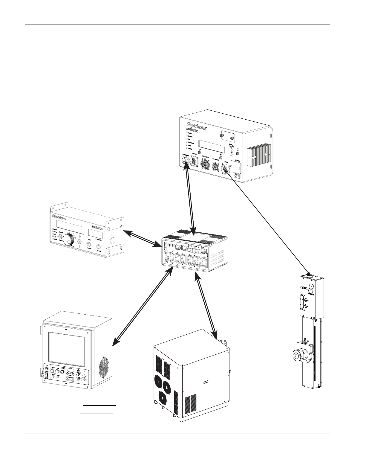
INSTALLATION
System description for a Hypernet configuration
The following diagram illustrates the cable and signal connections in a Hypernet communication configuration.
Note: Serial communication is transmitted over Hypernet cables.
Control module
HMI (optional)
CNC with Hypernet
Industrial
Ethernet switch
Lifter
HPR plasma system
with Hypernet
Key:
Hypernet connection
Discrete connection
2-10 ArcGlide THC Instruction Manual
2
Hypernet control and signal cables
Page 47
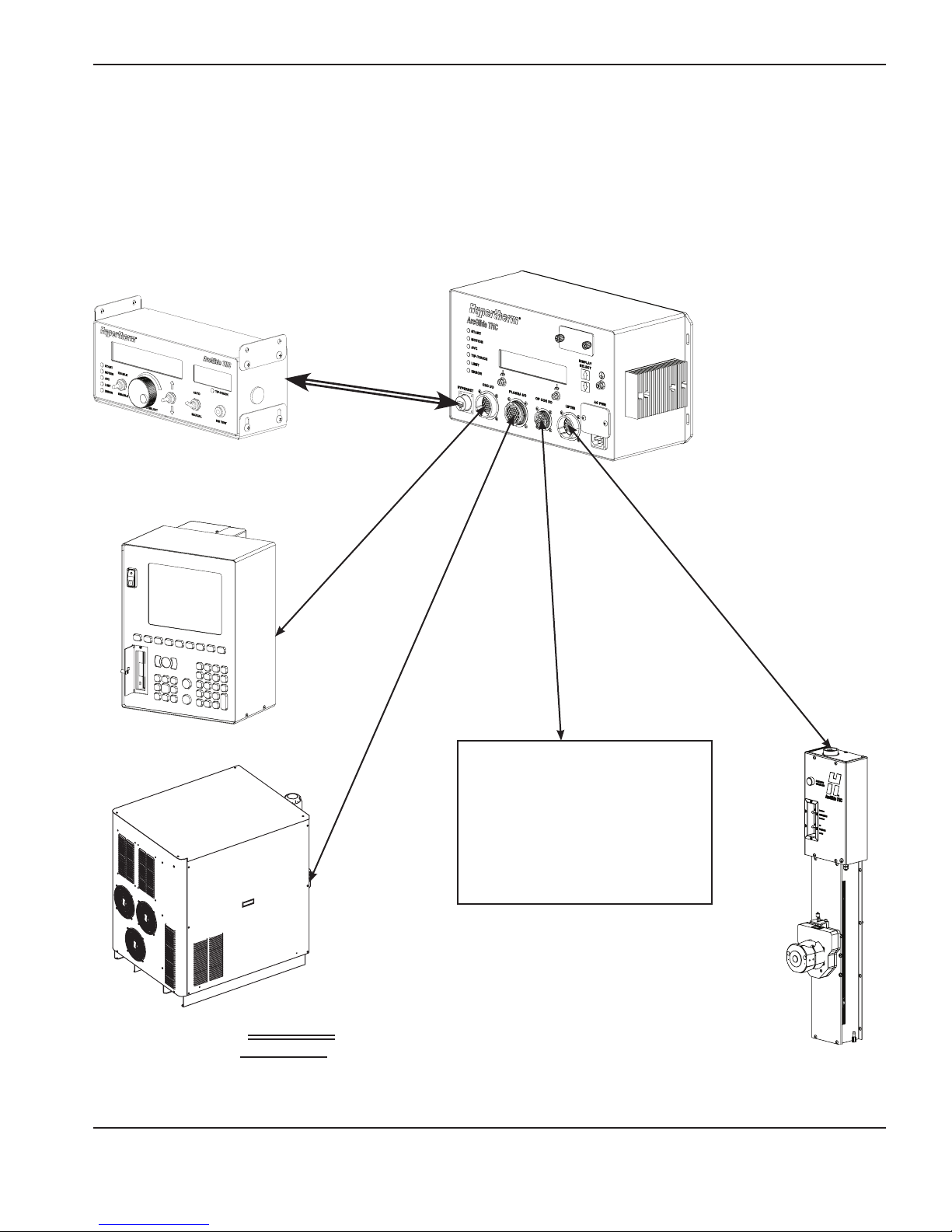
INSTALLATION
System description for a discrete configuration
The following diagram illustrates the cable and signal connections in a discrete communication configuration.
Note: For information on multidrop configurations, refer to the instruction manual for your plasma system.
HMI
Control module
CNC
Lifter
Plasma system
Customer-supplied operator console
(optional)
Station on/off/program switch
Station active light
Lifter up/down switch
Key:
Hypernet connection
Discrete connection
Discrete control and signal cables
ArcGlide THC Instruction Manual 2-11
2
Page 48

INSTALLATION
2-12 ArcGlide THC Instruction Manual
Page 49

ArcGlide THC Instruction Manual 2-13
Configuration examples
Multiple ArcGlide THCs with Hypernet connection to an EDGE Pro CNC and HPR or HPRXD plasma system
HYPERNET
(Optional) HMI
(Optional) HMI
EDGE Pro CNC
Rotary address
switch, set to 2
Rotary address
switch, set to 1
Shielded Ethernet cable, up to 61 m (200 ft)
5-, 8-, or 16-port industrial
Ethernet switch
Hypernet plasma interface
(141161), installed in plasma
system (below)
Rotary address
switch set to 1
HPR130, HPR260, HPR130XD,
HPR260XD, HPR400XD with
a built-in Ethernet adapter or
optional Ethernet kit.
Rotary address
switch set to 1
ArcGlide control module
Lifter interface cable
Rotary address
switch set to 2
ArcGlide control module
Interlock
ArcGlide
lifters
Rotary address
switch set to 2
Lifter interface cable
Hypernet plasma interface
(141161) installed in plasma
system (below)
Interlock
2
Page 50

2-14 ArcGlide THC Instruction Manual
ArcGlide THC with Hypernet connection to an EDGE Pro CNC and discrete connection to an HPR or HPRXD plasma system
HYPERNET
Plasma interface assembly (090052)
EDGE Pro CNC
DB37 to DB37 cable (123760)
HPR or HPRXD plasma system with discrete plasma interface (090052)
Plasma interface I/O cable
Interlock
Lifter interface cable
Rotary address switch, set to 1
ArcGlide lifter
Shielded Ethernet cable, up to
61 m (200 ft)
ArcGlide control module
DB37
DB37
DB50
Arc voltage sense wires
2
Page 51
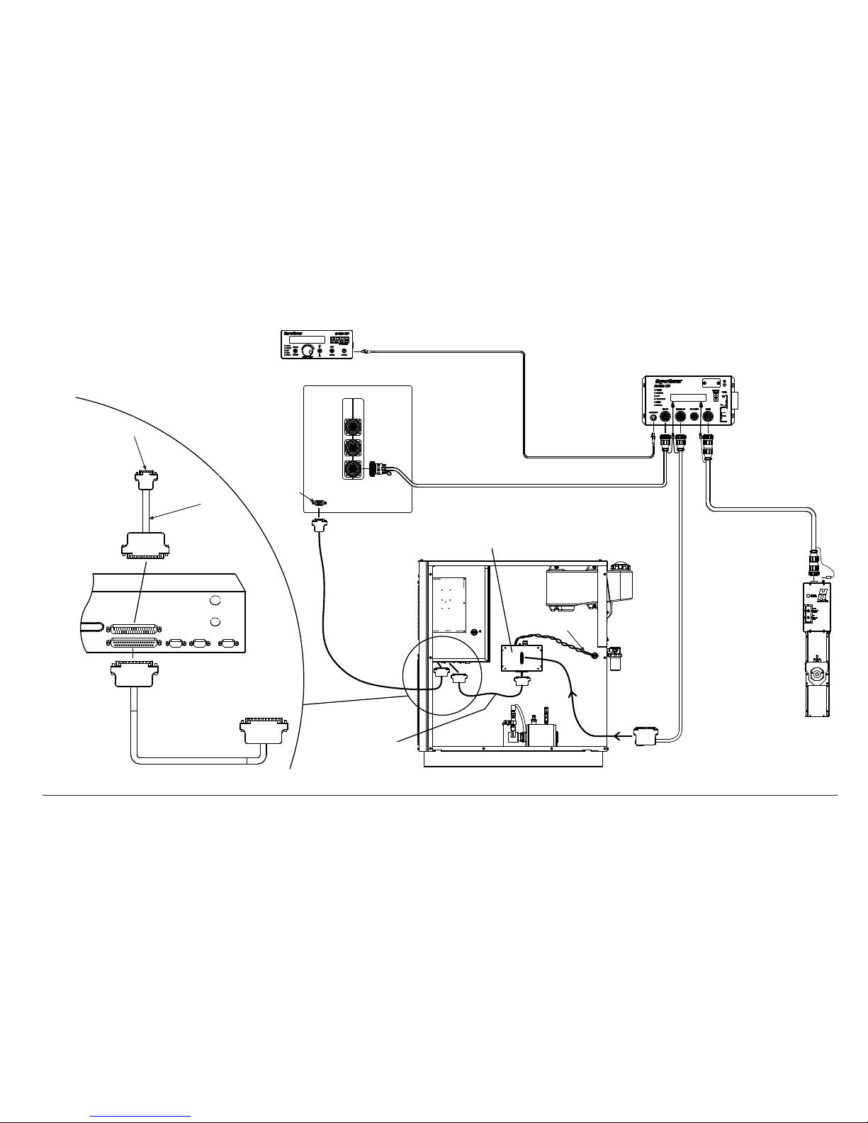
ArcGlide THC Instruction Manual 2-15
ArcGlide THC with discrete connection to a Picopath CNC and HPR or HPRXD plasma system
ArcGlide HMI
address 1
AXES 3,4
AXES 1,2
I/O
To CNC RS-422
port, terminate as
required
OEM-supplied
serial cable
DB37 female
HPR control PCB
DB37 male
Cable 223192
without serial
(with red
heatshrink)
Plasma interface (090052)
CNC I/O cable
Shielded Ethernet
cable
ArcGlide control
module address 1
Plasma interface cable
Arc voltage sense wires
Lifter interface cable
ArcGlide lifter
To plasma interface assembly
Cable 223192
without serial
(with red
heatshrink)
OEMsupplied
serial cable
ArcGlide
HMI address
1
DB37 female
RS-422 serial
port
CNC with Picopath interface and serial communication
Axes 3,4
Axes 1,2
I/O
DB50 male
2
Page 52
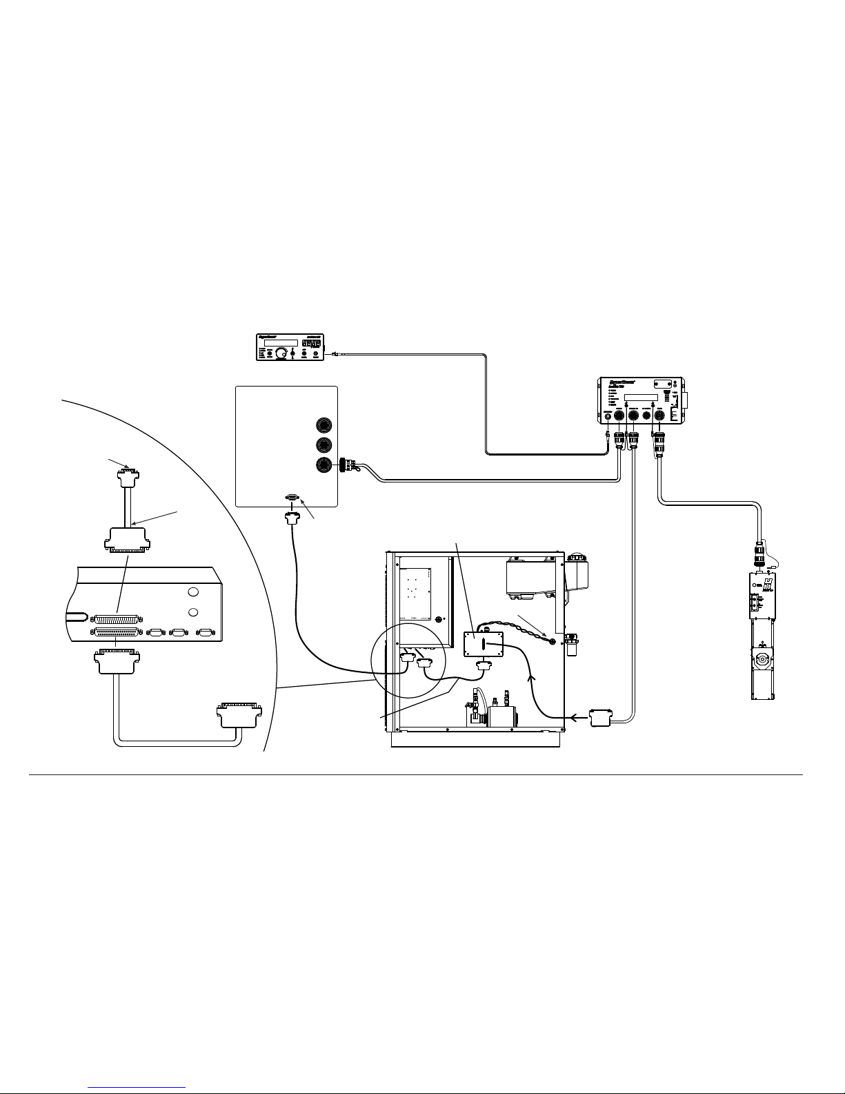
2-16 ArcGlide THC Instruction Manual
DB37F
DB37M
DB37F
To CNC RS-422 port,
terminate as required
OEM-supplied
serial cable
DB37 female
HPR control PCB
DB37 male
Cable 223192
without serial
(with red
heatshrink)
Plasma interface (090052)
CNC I/O cable
Shielded Ethernet cable
ArcGlide control module
address 1
Plasma interface cable
Arc voltage sense
wires
Lifter interface cable
ArcGlide lifter
To plasma interface
assembly
Cable 223192
without serial
(with red
heatshrink)
OEM-supplied serial
cable
DB37 female
RS-422 serial port
DB50 male
ArcGlide HMI
address 1
Generic CNC with serial communication
Axes 3,4
Axes 1,2
I/O
ArcGlide THC with discrete connection to a generic CNC and HPR or HPRXD plasma system
2
Page 53

ArcGlide THC Instruction Manual 2-17
ArcGlide THC with discrete connection to a generic CNC and HPR400XD
Shielded Ethernet cable
ArcGlide control module
address 1
ArcGlide HMI address 1
To CNC RS-422 port, terminate as
required
CNC I/O cable
Plasma interface cable
Lifter interface cable
ArcGlide lifter
DB50 male
Cable 223192 without serial
(with red heatshrink)
Arc
voltage
sense
wires
Plasma interface (090052)
DB37 female
Axes 3,4
Axes 1,2
I/O
Generic CNC with
serial communication
RS-422 serial port
OEM-supplied cable
2
Page 54

2-18 ArcGlide THC Instruction Manual
ArcGlide plasma interface with discrete connection to an HPR or HPRXD plasma system
PULL UP
* 24V
J2-2
FIELD COMMON
MOTION *
J2-1
COMMON
1
COMMON
J2-3
ERROR
FIELD COMMON
J2-4
J2-6
FIELD COMMON
RAMP ERROR
J2-5
COMMON
COMMON
J2-7
NOT READY
FIELD COMMON
J2-8
J2-10
FIELD COMMON
SPARE IN
J2-9
COMMON
COMMON
J2-11
COMMON
J2-12
COMMON
J2-13
J2-14
COMMON
J2-16
J2-15
J3-2
J3-1
CORNER B
RELAY
CORNER
CORNER A
J2
PIERCE A
PIERCE
RELAY
PIERCE B
J3-3
J3-4
J3-8
J3-7
PLASMA START **
RELAY
PLASMA START
PLASMA START A **
HOLD A
HOLD
RELAY
HOLD B
J3-5
J3-6
SPARE OUT A
SPARE
RELAY
SPARE OUT B
J3-9
J3-10
J3-12
J3-11
REMOTE ON B
RELAY
REMOTE ON
REMOTE ON A
J2-14
COMMON
COMMON
FIELD COMMON
J2-13
J2-15
+24V THC
FIELD +24V OUT
J2-16
FIELD +24V OUT
24V
J3
* 24V
PULL UP
PULL UP
* 24V
PULL UP
* 24V
FUTURE USE
NO CONNECT
NO CONNECT
FOR I/O USE IF NEEDED
500MA MAX
ARC XFER
D3
D4
THC ON
D2
PLASMA STRT
PLASMA ON
D1
16
1
16
Interface cable 123760
DB37 to DB37
To plasma system WORK +
To plasma system
Use ~0.9 mm squared (18 AWG) twisted
pair wire, rated 600 V or greater
To terminal block 2, pins 1 and 3
J3 OutputsJ2 Inputs
*Note: 24 V pullups on inputs are active only if they are set to dry on
the ArcGlide control module.
**Note: The minimum connections required are Plasma Start and
Motion. Use other signals if they are supported by the plasma
system.
To plasma system ELECTRODE -
Field 24 V out
Field 24 V out
Common
Common
Remote On B
Remote On A
Spare out B
Spare out A
Plasma Start B
Plasma Start A
Hold B
Hold A
Pierce B
Pierce A
Corner B
Corner A
Not connected
Not connected
Common
Common
Common
Common
Common
Spare in
Common
Not ready
Common
Ramp error
Common
Error
Common
Motion
Electrode (-)
Work (+)
J3
J2
Plasma interface (090052)
2
Page 55

ArcGlide THC Instruction Manual 2-19
ArcGlide THC with discrete communication to Picopath CNC and HSD130 plasma system
ArcGlide HMI address 1
ArcGlide control
module address 1
CNC with Picopath interface
HSD130
Plasma interface,
mounted externally by
customer.
Plasma interface I/O cable
Interface cable 123209
Arc voltage sense wires. Use ~0.9 mm squared (18 AWG) twisted pair
wire, rated 600 V or greater
Electrode (-)
Work (+)
CNC I/O cable
Lifter interface cable
Shielded Ethernet cable
DB50
DB37
ArcGlide lifter
Axes 3,4
Axes 1,2
I/O
DB37
Plasma
interface
(090052)
2
Page 56

2-20 ArcGlide THC Instruction Manual
ArcGlide THC with discrete connections to Picopath CNC and MAX200, HT2000, or HT2000LHF plasma system
MACHINE
1X6
Lifter interface cable
ArcGlide control module
address set to 1
ArcGlide HMI
address set to 1
CNC with Picopath interface
Plasma interface I/O cable
CNC I/O cable
Shielded Ethernet cable
ArcGlide lifter
To plasma system
Use ~0.9 mm squared (18 AWG) twisted pair wire, rated 600 V or greater
Plasma interface (090052)
1x6 Machine interface cable
Axes 3,4
Axes 1,2
I/O
MAX200
2
Page 57
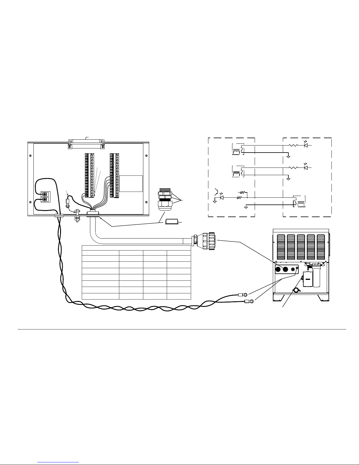
ArcGlide THC Instruction Manual 2-21
ArcGlide plasma interface with discrete connection to MAX200, HT2000, or HT2000LHF plasma system
IHS SYNC
J3-5
J3-6
HOLD
1
HOLD - WHT
RELAY
RELAY
PLASMA START
PULL UP
24V
J2-2
FIELD COMMON
MOTION - RED
START - BLU
J2-1
J3-8
J3-7
HOLD IGNITION
MACHINE MOTION
DELAYED
36(37)
31(32)
HOLD - BLK
MOTION - BLU
9
START
START - BLK
15
5
COMMON
COMMON
( ) - FOR HT2000, HT2000LHF
+24V
+24V
MAX200
To plasma system
WORK +
To plasma system
Use ~0.9 mm squared (18 AWG) twisted pair wire, rated 600 V or greater
To plasma system
ELECTRODE -
The plasma interface is mounted
externally by the customer.
No connection
Electrode (-)
Work (+)
Remove
Replace with
bushing 008245
Refer to HT2000, HT2000LHF manual
for the 1x6 connection.
1x6 Machine interface cable
Plasma interface termination
Signal Wire color Pin Cable label
Plasma Start A Blue 9 82
Plasma Start B Black 15 83
Hold A White 1 87
Hold B Black 5 86
Motion Red 36 (37) 84
Common Blue 31 (32) 85
Ring terminal to ground stud Shield wire No connection
For HT2000 and HT2000LHF, set
ArcGlide plasma inputs to dry contact
by sliding the switch on the control
module to D.
Numbers in () refer to HT2000 and
HT2000 LHF.
ArcGlide plasma interface
terminal blocks
Machine interface 1x6 CPC connector
Plasma Start B
Plasma Start A
Hold B
Hold A
Black
Blue
Common
Motion
Blue
Red
Shield
1
1
J2
J3
1616
Black
White
2
Page 58
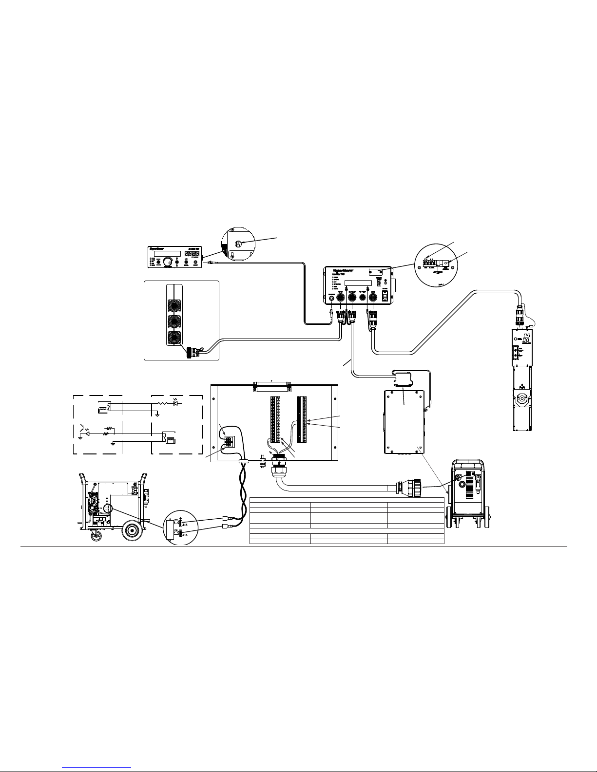
2-22 ArcGlide THC Instruction Manual
ArcGlide plasma interface connection to Powermax G3 series plasma system
ARCGLIDE PLASMA INTERFACE
POWERMAX MACHINE
RELAY
PLASMA START
PULL UP
24V
J2-2
FIELD COMMON
MOTION - RED
START - GRN
INTERFACE CONNECTOR
J2-1
TERMINAL BLOCKS
J3-8
J3-7
MACHINE MOTION
13
14
MOTION - BLK
3
START
START - BLK
4
COMMON
+24V
Rotary address switch,
set to 1.
ArcGlide control module
CNC with Picopath interface
Axes
3, 4
Axes
1, 2
I/O
Rotary address
switch, set to 1
ArcGlide HMI
Arc voltage sense wires. Use
~0.9mm squared (18AWG)
twisted pair wire, rated 600V or
greater
Plasma interface I/O cable
CNC I/O cable
ArcGlide lifter
No connection
Powermax G3
CAT- 5e shielded
Ethernet cable
Plasma
interface
(090052),
mounted by
the customer.
Powermax machine interface cable 023206
To Powermax
J15+
To Powermax
J16-
Plasma interface termination
Signal Wire color Pin
Plasma Start A Green 3
Plasma Start B Black 4
Motion Red 13
Common Black 14
Arc voltage
Electrode (-) ~0.9 mm squared (18 AWG) J16
Work (+) ~0.9 mm squared (18 AWG) J15
Set dry contacts by
sliding the switch to D.
Lifter interface cable
ArcGlide plasma interface
terminal blocks
Powermax machine
interface connector
Electrode (-)
Work (+)
Powermax G3
Plasma Start B
Plasma Start A
Common
Motion
Black
Green
Black
Red
1
1
J2 J3
16
16
2
Page 59

ArcGlide THC Instruction Manual 2-23
A
17
18
INPUT 12
OUTPUT 10
OUTPUT 11
OUTPUT 12
5
7
1
26
25
INTERLOCK
12
32
31
30
MOTION
CYCLE START
AVC DISABLE
IHS SYNC
24V COMMON COMMON
31
24V
PULL UP
24V
PULL UP
24V
PULL UP
CYCLE START
RELAY
RELAY
BREAKAWAY
BREAKAWAY
37
11
INPUT 11
22
21
COMMON
JUMPER
JUMPER
COMMON
29
30
TORCH
B
D S D S
CNC PLASMA
INPUT
24V
+24V
+24V
ArcGlide CNC interface with discrete connection to a Picopath CNC
ArcGlide control
module
Set dry contacts by sliding
the switch to D.
ArcGlide CNC
interface cable
CNC with Picopath interface
Picopath connector kit
(228490)
Axes 3, 4
Axes 1,2
I/O
Picopath CNC end A
ArcGlide control module end B
Picopath CNC end (A), terminated during installation ArcGlide end (B), terminated by Hypertherm
Pin Function Phoenix mapping name Wire color Pin Signal
32 Output 12 Cut control Red 1 Cycle start input+
31 Output 11 Hold ignition Blue 7 IHS sync input+
30 Output 10 Torch height disable Green 5 AVC disable input +
12 Input 12 Cut sense 1 Green 17 Machine motion output A
Jumper together
⊂
Red 18 Machine motion output B
Blue 29 Common
11 Input 11 Torch collision Yellow 21 Torch breakaway output A
Jumper together
⊂
Red 22 Torch breakaway output B
Green 30 Common
External switch
Orange 25 Interlock input+
Red 26 Interlock input -
37 24 V Common Yellow 31 Common
Backshell Ground Ground
• Start with Hypertherm-supplied ArcGlide CNC interface cable and terminate the Picopath end.
• This example uses CNC outputs 10, 11, 12, and inputs 11 and 12. Map I/O in Phoenix software accordingly.
• Multiple wires are the same color. Verify pin-to-pin connections before plugging cables into equipment.
• Incorrect wiring can cause permanent damage to Picopath or ArcGlide circuits.
• Set ArcGlide CNC inputs to dry with the slide switch on the control module.
• ArcGlide interlock must be satisfied (closed) to enable ArcGlide motion.
2
Page 60
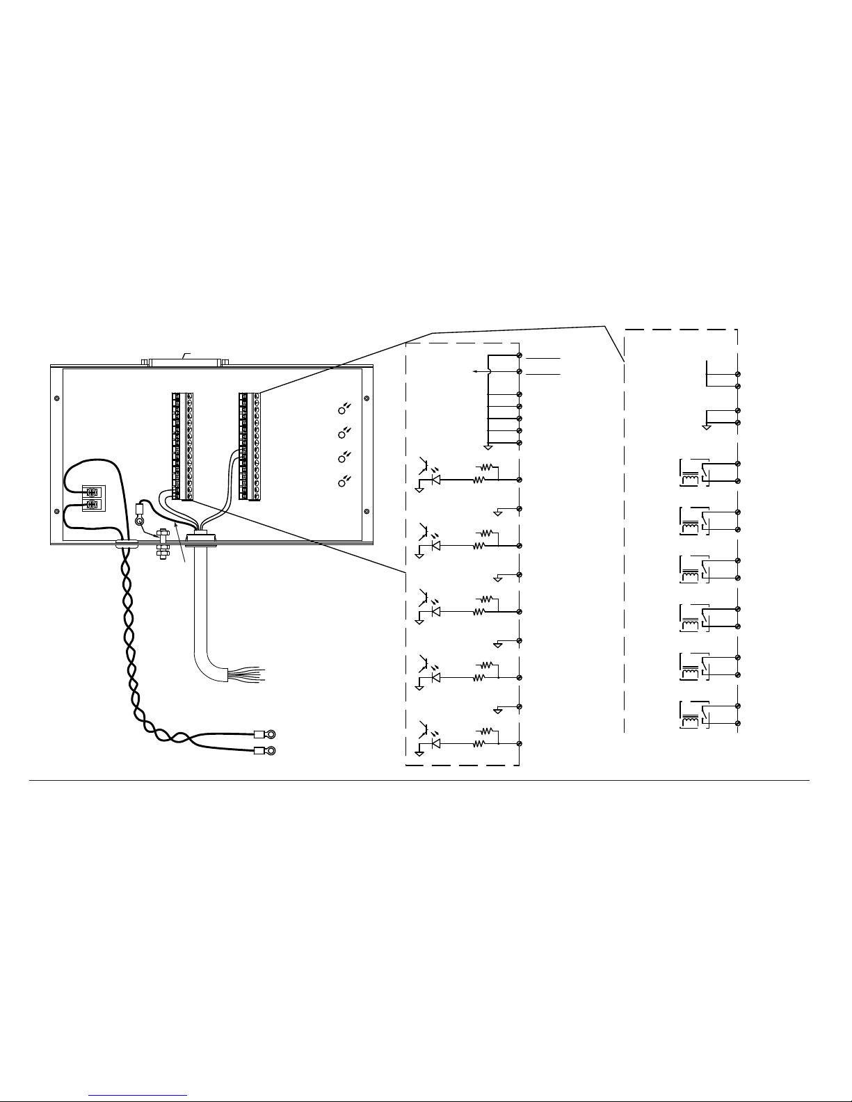
2-24 ArcGlide THC Instruction Manual
ArcGlide plasma interface discrete connection to any plasma system
PULL UP
* 24V
J2-2
FIELD COMMON
MOTION **
J2-1
COMMON
1
COMMON
J2-3
ERROR
FIELD COMMON
J2-4
J2-6
FIELD COMMON
RAMP ERROR
J2-5
COMMON
COMMON
J2-7
NOT READY
FIELD COMMON
J2-8
J2-10
FIELD COMMON
SPARE IN
J2-9
COMMON
COMMON
J2-11
COMMON
J2-12
COMMON
J2-13
J2-14
COMMON
J2-16
J2-15
J3-2
J3-1
CORNER B
RELAY
CORNER
CORNER A
PIERCE A
PIERCE
RELAY
PIERCE B
J3-3
J3-4
J3-8
J3-7
PLASMA START **
RELAY
PLASMA START
PLASMA START A **
HOLD A
HOLD
RELAY
HOLD B
J3-5
J3-6
SPARE OUT A
SPARE
RELAY
SPARE OUT B
J3-9
J3-10
J3-12
J3-11
REMOTE ON B
RELAY
REMOTE ON
REMOTE ON A
J2-14
COMMON
COMMON
FIELD COMMON
J2-13
J2-15
+24V THC
FIELD +24V OUT
J2-16
FIELD +24V OUT
24V
* 24V
PULL UP
PULL UP
* 24V
PULL UP
* 24V
FUTURE USE
NO CONNECT
NO CONNECT
FOR I/O USE IF NEEDED
500MA MAX
ARC XFER
D3
D4
THC ON
D2
PLASMA STRT
PLASMA ON
D1
16
1
16
* 24V
PULL UP
To plasma system
WORK +
J3 OutputsJ2 Inputs
To plasma system
ELECTRODE -
Field 24 V out
Field 24 V out
Common
Common
Remote On B
Remote On A
Spare out B
Spare out A
Plasma Start B
Plasma Start A
Hold B
Hold A
Pierce B
Pierce A
Corner B
Corner A
Not connected
Not connected
Common
Common
Common
Common
Common
Spare in
Common
Not ready
Common
Ramp error
Common
Error
Common
Motion
Electrode (-)
Work (+)
Arc voltage sense wires. Use
~0.9 mm squared (18 AWG)
twisted pair wire, rated 600 V or
greater
Shield
*Note: 24 V pullups on inputs are active only if they are set to “dry” on the
ArcGlide control module.
**Note: The minimum connections required are Plasma Start and Motion.
Use other signals if they are supported by the plasma system
J3
J2
No connection
To plasma system
machine interface
Plasma interface (090052)
2
Page 61
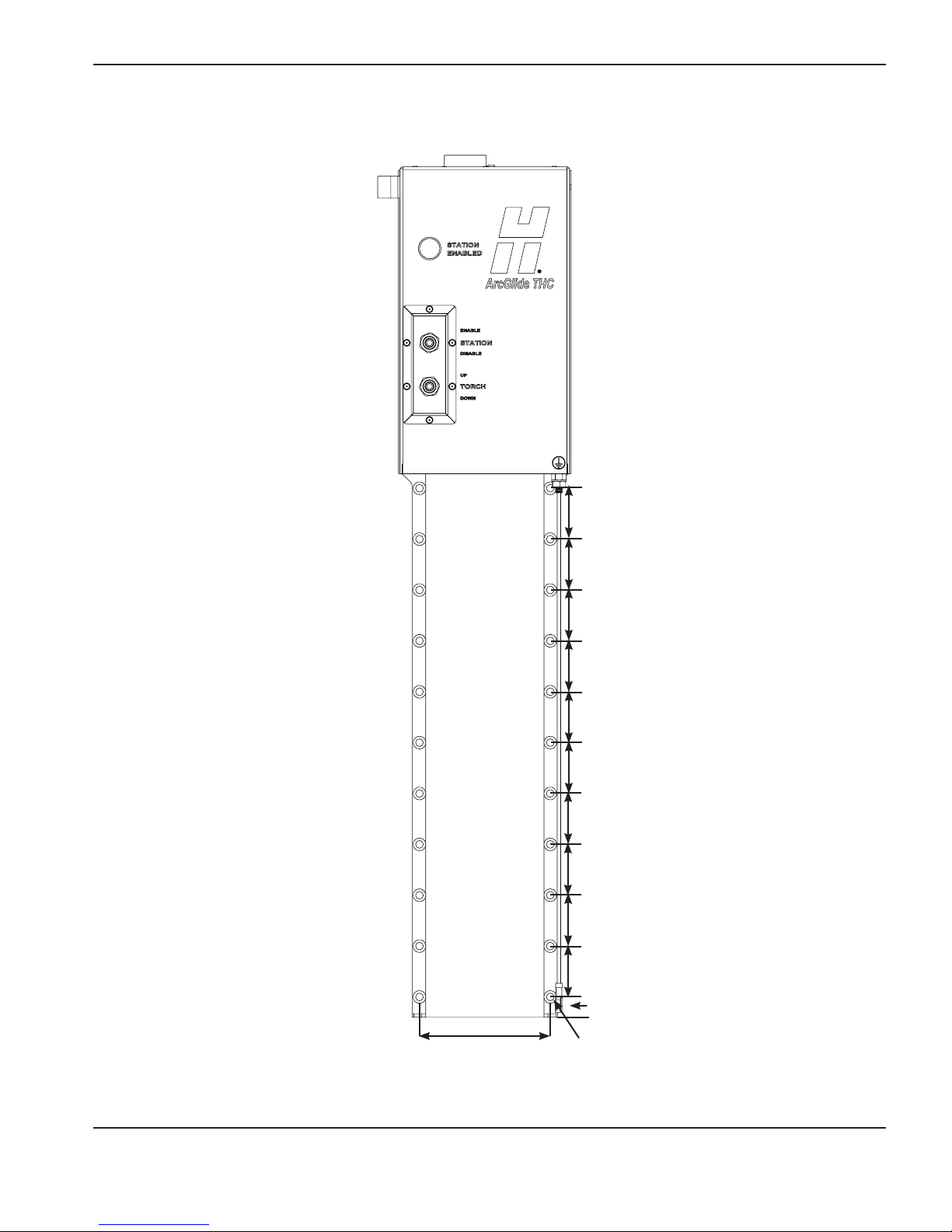
Install the lifter
INSTALLATION
44.45 mm (1.75”)
44.45 mm (1.75”)
44.45 mm (1.75”)
44.45 mm (1.75”)
44.45 mm (1.75”)
44.45 mm (1.75”)
44.45 mm (1.75”)
44.45 mm (1.75”)
44.45 mm (1.75”)
ArcGlide THC Instruction Manual 2-25
44.45 mm (1.75”)
114.3 mm
4.5”
6.7 mm
(0.266 in.)
diameter
Lifter mounting dimensions
17.8 mm (.7”)
Page 62

INSTALLATION
1. Position the lifter on the gantry:
• Low enough that the torch can reach the workpiece.
• High enough that the torch does not touch the table.
• The bottom of the lifter must be within 20.32 cm (8.00”) of the thinnest
workpiece.
• Mounting holes have the same spacing as the Sensor THC and Command THC
lifters.
2. Mount the lifter on the gantry:
a. Remove the side panels to expose the mounting screw holes.
b. Loosely fasten the screws in a diagonal pattern, top to bottom and right to left
(see the numbers in the illustration on right.)
c. Use a minimum of 4 screws to mount the lifter.
d. Place a level vertically along the side of the lifter to verify that it is mounted
vertically.
e. Tighten the screws using a maximum torque of 0.9 newton meter (8.0 inch
pounds).
f. When they are tightened, the tops of the screws must be below the surface of the
back panel of the lifter so the side panels can be replaced.
g. Reinstall the side panels.
1
3
b
5
d
3. Connect the lifter interface cable and secure it.
a. The cable connector is not rated for hard use or constant flexing. Support the
cable and add enough slack to prevent strain on the cable and prevent damage to
the cable assembly, lifter connector, or both.
b. Use the cable clamp that is included with the lifter to secure the cable to either
side of the lifter with a generous service loop.
c. Connect the cable ground to the ground connector on the top of the lifter.
Level
Side
panel
Side
panel
6
2
4
a
c
b
2-26 ArcGlide THC Instruction Manual
2
Page 63
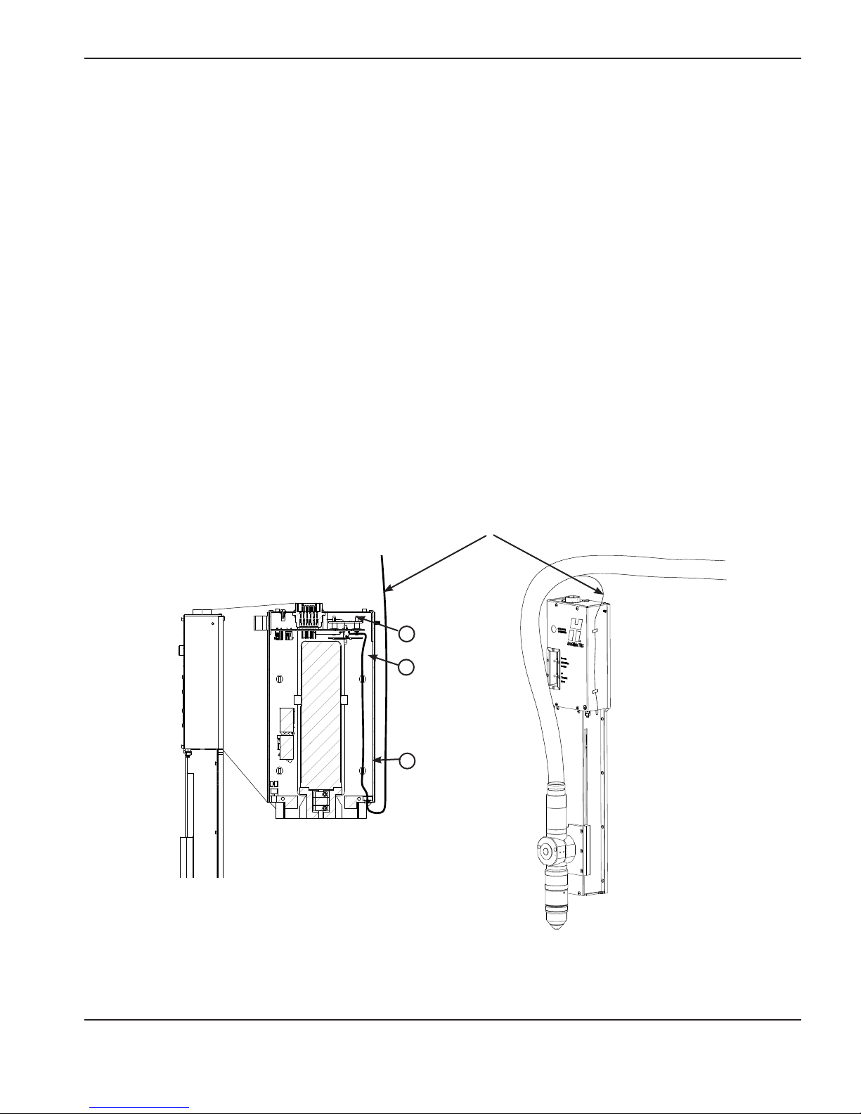
INSTALLATION
Connect the Ohmic wire to HPR XD plasma systems
Note Do not splice Ohmic wires.
To connect the Ohmic wire from an HPR XD torch to the ArcGlide lifter:
1. Remove the top cover of the motor compartment on the lifter.
2. Disconnect the existing Ohmic wire from the J5 connector on the underside of the lifter interface.
3. Remove the Ohmic wire from the motor compartment of the lifter.
4. Cut the terminal end off the Ohmic wire from the HPR XD torch and strip 5 mm (0.2 in) of the covering.
5. Insert the end of the Ohmic wire from the HPR XD system through the grommet in the bottom of the motor
compartment of the lifter.
6. Insert the stripped HPR XD Ohmic wire into the J5 connector on the underside of the lifter interface PCB.
7. Use tywraps to fasten the wire to the tywrap mounts on the inside back wall of the lifter compartment.
8. Refasten the top cover of the motor compartment.
Ohmic wire from HPR XD plasma system
Rear half of lifter compartment
Side of lifter
6
7
5
Connect the Ohmic wire for an HPR XD plasma system
ArcGlide THC Instruction Manual 2-27
2
Page 64

INSTALLATION
Connect the Ohmic wire to other plasma systems
Note Do not splice Ohmic wires.
If your plasma system is not an HPR XD system, connect the ArcGlide Ohmic wire to the torch:
1. Unfasten the tywrap around the coiled Ohmic wire and straighten the Ohmic wire.
2. Install the free end of the Ohmic wire on the IHS tab on the torch retaining cap.
2-28 ArcGlide THC Instruction Manual
2
2
Connect the Ohmic wire
Page 65
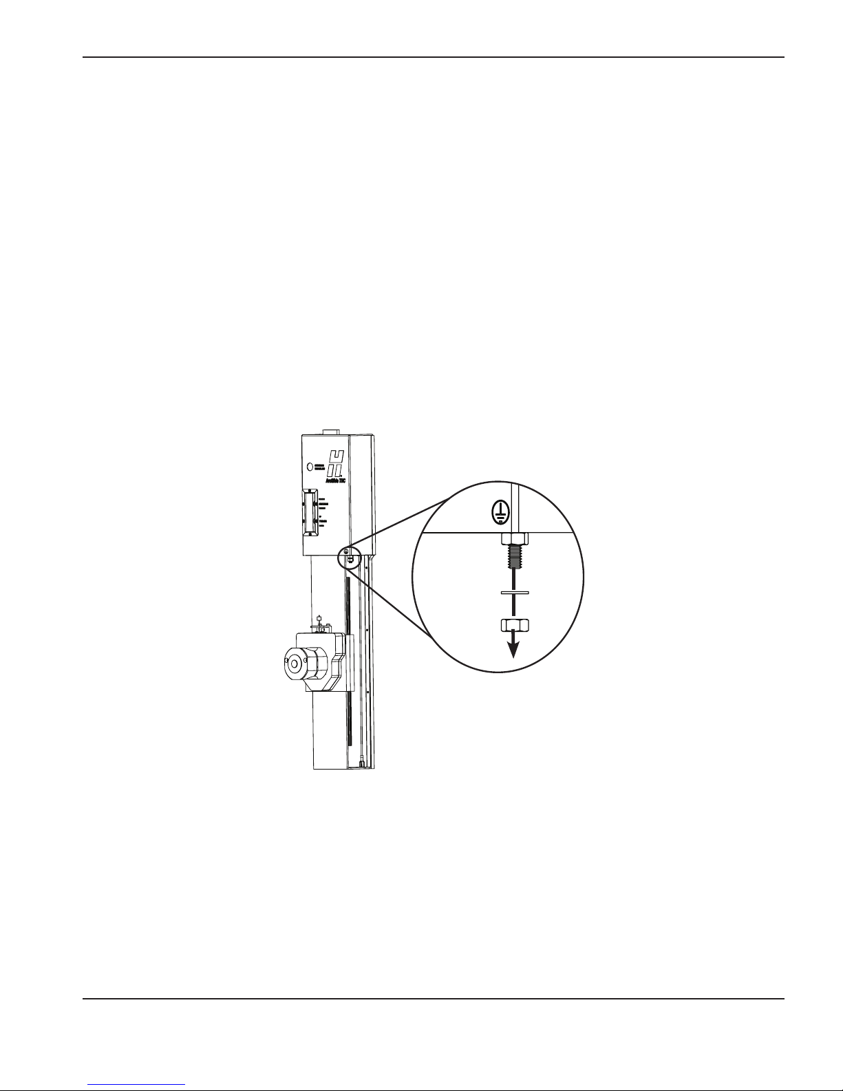
INSTALLATION
Ground the lifter
The lifter must be grounded correctly to insure accurate initial height sense (IHS)
To ground the lifter:
1. Remove the bottom nut and washer of the grounding assembly on the lifter.
2. Fit the ground wire terminal on the ground wire over the grounding post.
3. Replace the bottom nut and washer on the ground post and finger-tighten it so the ground terminal is in contact with
the washer and bottom nut.
4. Connect the other end of the ground wire to a terminal on the bus bar on the cutting table.
5. Ensure that the wire is not in the path of the lifter mechanics
For more information, see Recommended grounding and shielding practices.
ArcGlide THC Instruction Manual 2-29
Ground the lifter
2
Page 66

INSTALLATION
Install the control module
381.00 mm
(15.37”)
168.91 mm
(6.65”)
71.63 mm
(2.82”)
107.95 mm
(4.25”)
Control module front
5 mm (0.201 in.)
wide
358.65 mm
(14.12”)
6 mm (0.25”)
bolt
371.35 mm
(14.62”)
25.40 mm
(1.00”)
157.23 mm
(6.19”)
166.62 mm
(6.56”)
Control module right side
165.00 mm
(6.50”)
127.00 mm
(5.00”)
2-30 ArcGlide THC Instruction Manual
377.70 mm
(14.87”)
Control module mounting dimensions
Page 67

INSTALLATION
Install the control module where it will be easy to read the display and to reach the controls during installation and
troubleshooting. A dry, dust-free wiring cabinet is ideal. Leave clearance space of 20.32 cm (8.00 in) from the front of
the control module and 6.35 mm (0.25 in) from the heatsink.
1. Mount the control module with four screws.
2. Connect the end of the lifter interface cable with the red band to the connector marked Lifter (with the red circle).
Refer to Connect Hypernet cables or Connect discrete cables for more information on connecting cables to the
control module.
3. Attach one end of the power cord to the AC Power connector on the front of the control module. Prepare the other
end for the 120/240 VAC power outlet.
Ground the control module
To ground the controI module:
1. Remove the top nut and washer of the grounding assembly on the front of the control module.
2. Fit the ground wire terminal over the grounding post.
3. Replace the top nut and washer on the ground post and finger-tighten it so the ground terminal is in contact with the
washer and bottom nut.
4. Connect the other end of the ground wire to a terminal on the bus bar on the cutting table.
For more information, see Recommended grounding and shielding practices.
ArcGlide THC Instruction Manual 2-31
Ground the control module
Page 68

INSTALLATION
Install the optional HMI
117.60 mm
(4.63”)
HMI module front
298.00 mm
(11.73”)
19.43 mm
(0.77”)
130.58
mm
(5.14”)
101.60 mm
(4.00”)
65.00 mm
(2.50”)
20.00 mm
(0.79”)
10-32 x 9.52 mm
(3/8”) Phillips head
screw
9.55 mm
(0.38”)
HMI right side
5 mm (0.201
63.50 mm
(2.50”)
203.20 mm
(2.50”)
in.) diameter
HMI mounting dimensions
The mounting brackets on the top and bottom of the HMI allow you to install it singly or stacked, under or on another
piece of equipment, and level or tilted.
HMI mounted on a surface and
tilted up.
HMI mounted on a surface
and tilted down.
2-32 ArcGlide THC Instruction Manual
Two HMIs stacked and
mounted level under a
surface.
Page 69

INSTALLATION
To install the HMI:
1. Remove the mounting bracket from the HMI.
2. Place the mounting bracket on the surface where you will mount the HMI and attach the bracket with screws through
the holes in the bottom of the bracket.
3. Remount the HMI in the mounting bracket by loosely fastening the screws through the sides of the bracket into the
top or bottom holes in the sides of the HMI.
4. Adjust the HMI to the angle you want it and tighten the screws.
5. Attach one end of the power cord to the AC Power connector on the back of the HMI. Prepare the other end for the
120/240 VAC power outlet.
Ground the HMI
To ground the HMI:
1. Remove the top nut and washer of the grounding assembly on the back of the HMI.
2. Fit the ground wire terminal over the grounding post.
3. Replace the top nut and the washer on the ground post and finger-tighten it so the ground terminal is in contact with
the washer and bottom nut.
4. Connect the other end of the ground wire to a terminal on the bus bar on the gantry of the cutting table.
For more information, see Recommended grounding and shielding practices.
ArcGlide THC Instruction Manual 2-33
Ground the HMI
Page 70

INSTALLATION
123456
Connect Hypernet cables
A system configuration in which there is more than one Hypernet span requires an industrial-grade Ethernet switch. For
more information on the requirements for this switch, see Specifications.
In this type of configuration, the Hypernet links are made from the ArcGlide directly to the Ethernet switch and from
there to the CNC or plasma system. See System description for a Hypernet configuration, earlier in this section.
Notes: Each unit that is assigned to a station must have the same Hypernet unit address. This common unit
address allows the Ethernet switch to direct communications to the units at the appropriate station.
See the Maintenance section for the location of the unit address switches on the PCBs.
Hypernet connections and Ethernet connection to a LAN cannot be made through the same switch. If
your cutting system is connected to a LAN over Ethernet, you must use a separate Ethernet switch for
these connections.
To power supply 1
+
Power connections to the Ethernet switch
- -
To power supply 2
+
Hypernet connections to the Ethernet switch
It is also possible to have a mixed Hypernet and discrete configuration in which the ArcGlide THC communicates with
only the CNC or plasma system over Hypernet and uses discrete communication for the alternate link. Use the portions
of the following instructions that apply to your configuration.
1. Use a Hypernet cable to connect the control module
to the Ethernet switch:
a. Insert one end of the Hypernet cable into the
Hypernet connector on the front of the control
module.
b. Insert the other end of the cable into one of the
ports of the Ethernet switch.
2-34 ArcGlide THC Instruction Manual
2
To the Ethernet switch
Page 71

2. Use a Hypernet cable to connect the CNC to the
Ethernet switch:
a. Insert one end of the Hypernet cable into the
Hypernet port on the back of an EDGE Pro CNC or
to a Hypernet-configured, dedicated Ethernet port
on any other CNC.
b. Insert the other end of the cable into one of the
ports of the Ethernet switch.
To the Ethernet
switch
3. Use a Hypernet cable to connect the plasma system to the
Ethernet switch:
INSTALLATION
a. Insert one end of the Hypernet cable into the Hypernet
port on the plasma interface board in the plasma system.
b. Insert the other end of the cable into one of the ports of
the Ethernet switch.
Refer to the manual for your plasma system for detailed
instructions about these connections.
4. If your configuration includes the optional HMI, use a
Hypernet cable to connect it to the Ethernet switch:
To the
Ethernet
switch
a. Insert one end of the Hypernet cable into the Hypernet
port on the HMI.
b. Insert the other end of the cable into one of the ports of
the Ethernet switch.
ArcGlide THC Instruction Manual 2-35
To the Ethernet switch
Page 72

INSTALLATION
Connect discrete cables
In a discrete configuration, the communication links are made from the control module to the HMI, CNC, plasma system,
and optional operator console. In this type of configuration, the control module and HMI communicate over a single
span of Hypernet. This is the only configuration that does not require an Ethernet switch. See System description for a
discrete configuration, in this section.
It is also possible to have a mixed Hypernet and discrete configuration in which the ArcGlide THC communicates with
the CNC, the plasma system, or both over discrete connections and uses Hypernet communication for the remaining
link. In configurations where there is more than one span of Hypernet, an industrial-grade Ethernet switch is required for
the Hypernet connections.
Use the portions of the following instructions that apply to your configuration.
Note: Each port on the front of the control module is color-coded to match the connector on the interface cable
that connects to it, as shown in the illustrations for each cable later in this section.
1. Connect the HMI to the control module:
a. Insert one end of the HMI cable into the Hypernet
connector on the front of the control module.
b. Insert the other end of the cable into the Hypernet port
on the back of the HMI.
Connection between the HMI and
the control module
Ground all cables with circular connectors:
1. Remove the top nut and washer of the grounding assembly.
2. Fit the ground wire terminal on the cable over the grounding post.
3. Replace the top nut and the washer on the ground post and finger-tighten it so the
ground terminal is in contact with the washer and bottom nut.
For more information, see Recommended grounding and shielding practices.
2. Connect the CNC to the control module:
a. Insert the end of the CNC I/O cable with the yellow band
into the CNC I/O connector on the front of the control
module.
b. Connect the wires on the other end of the cable to the
I/O signals on the CNC.
For more information, see the description of the CNC I/O
cable, later in this section.
2-36 ArcGlide THC Instruction Manual
Discrete connection to the CNC
Page 73

3. Connect the plasma system to the control module:
a. Insert the end of the plasma interface I/O cable with the
blue band into the Plasma I/O connector on the front of
the control module.
b. Connect the other end of the cable into the plasma I/O
connector (J5) on the plasma interface PCB in the plasma
system.
For more information, see the description of the plasma I/O
cable, later in this section.
INSTALLATION
Discrete connection to
the plasma system
4. If your configuration includes a, optional, customized
operator console, connect it to the control module:
a. Connect the end of the operator console I/O cable with
the green band into the operator console I/O connector
on the front of the control module.
b. Connect the other end of the cable into the appropriate
connectors on the custom operator console.
For more information, see the description of the operator
console I/O cable, later in this section.
5. Use the instructions in Install the lifter in this section to
connect the ArcGlide lifter to the control module.
Discrete connection to
the operator console
ArcGlide THC Instruction Manual 2-37
Discrete connection to the lifter
Page 74

INSTALLATION
Cables
Lifter interface cable
Red band
Connect one end to the
connector on the control
module with the red
circle.
Part number Length Part number Length
223219 3.0 m (10 ft) 223115 23.0 m (75 ft)
223220 6.0 m (20 ft) 223116 30.5 m (100 ft)
223120 7.5 m (25 ft) 223117 45.5 m (150 ft)
223221 10.5 m (35 ft) 223118 61.0 m (200 ft)
223007 15.0 m (50 ft)
Pin number* Color Signal name
1 Red (16 AWG) Motor +
2 Black (16 AWG) Motor –
3 Black (18 AWG) Brake –
4 Brown (22 AWG) Common –
5 Brown (18 AWG) Power +24 VDC
6 Gray (22 AWG) Ohmic contact sense common
7 White (22 AWG) Ohmic contact sense
8 Violet (22 AWG) Ohmic contact sense bias +12 VDC
9 Black (22 AWG) Encoder common
10 Red (22 AWG) Lifter station active
11 White/Blue (22 AWG) Encoder input B –
12 Blue (22 AWG) Encoder input B +
13 White/Yellow (22 AWG) Encoder input A –
14 Yellow (22 AWG) Encoder input A +
15 White/Black (22 AWG) Common –
16 White/Red (22 AWG) Change consumables switch+
17 Green (22 AWG) Lifter down switch +
18 Orange (22 AWG) Lifter up switch +
19 White/Violet (22 AWG) Breakaway switch+
20 White/Orange (22 AWG) Upper limit switch +
21 White/Green (22 AWG) Lower limit switch +
22 White/Gray (22 AWG) Not connected
23 White/Brown (22 AWG) Common –
24 Not connected
* Pin numbers are the same on both ends of the cable.
Connect one end to
the top of the lifter.
2-38 ArcGlide THC Instruction Manual
Page 75

Hypernet and HMI interface cable
INSTALLATION
Connect this end to
the control module
or Ethernet switch.
Pin number* Signal name
1 TX + (transmit data +)
2 TX – (transmit data –)
3 RX + (receive data +)
4 Not connected
5 Not connected
6 RX – (receive data –)
Connect this end to the
ArcGlide HMI.
In a Hypernet or mixed configuration where there is more
than one Hypernet span, use these cables to connect the
components of the system to the Ethernet switch.
If you use Ethernet cable from another supplier, verify that
the cable is a standard, shielded RJ-45 Cat-5e cable.
Part number Length
223212 3.0 m (10 ft)
2232222 6.0 m (20 ft)
223119 7.5 m (25 ft)
223223 10.5 m (35 ft)
223008 15.0 m (50 ft)
223099 23.0 m (75 ft)
7 Not connected
8 Not connected
* Pin numbers are the same on both ends of the cable.
223100 30.5 m (100 ft)
223101 45.5 m (150 ft)
223102 61.0 m (200 ft)
ArcGlide THC Instruction Manual 2-39
Page 76
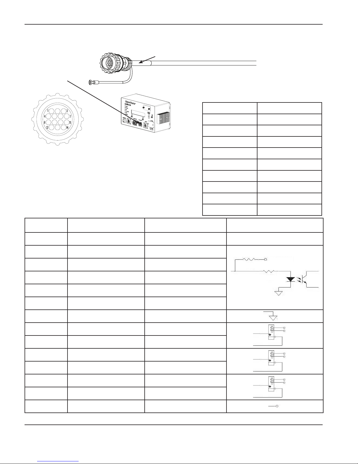
INSTALLATION
BAB
A
B
A
Operator console I/O cable
Connect this end to
the connector on the
control module with
the green circle.
Green band
Add the appropriate
connector for your
console on this end.
Contact your console
supplier for additional
information.
Part number Length
223216 3.0 m (10 ft)
223217 6.0 m (20 ft)
223121 7.5 m (25 ft)
Notes:
223218 10.5 m (35 ft)
• Input signals (pins 2 – 6) use 24 VDC; Output signals (pins
8 – 14) use dry contact closures at 24 VDC.
• For more information about discrete operator console I/O
223006 15.0 m (50 ft)
223111 23.0 m (75 ft)
223112 30.5 m (100 ft)
signals, see ArcGlide discrete interface signals.
223113 45.5 m (150 ft)
223114 61.0 m (200 ft)
Pin number* Color Signal name Dry contact circuit
1 Black Not connected
2 White Manual disable switch input +
+24 V
3 Red Manual select switch input +
4 Green Torch up switch input +
3.9 K
3.9 K
5 Orange Torch down switch input +
6 Blue Spare switch input +
7 White/black Common
8 Red/black Torch enabled output A
9 Green/black Torch enabled output B
10 Orange/black Error output A
11 Blue/black Error output B
12 Black/white Spare output A
13 Red/white Spare output B
14 Green/white Power +24 VDC output
* Pin numbers are the same on both ends of the cable.
2-40 ArcGlide THC Instruction Manual
2
A
B
A
B
A
B
+24 V
normally
open
normally
open
normally
open
Page 77

INSTALLATION
_
ArcGlide motor control CNC interlock kit (228594)
As part of a motion control system, the ArcGlide has an interlock to enable and disable Z-axis motion. This interlock
must be wired correctly and according to the appropriate national and local codes to allow the quick stop of motion.
The interlock must be closed (pins 25 and 26) to enable the Z-axis motion of the ArcGlide.
The interlock kit includes the connector, backshell, and pins that are necessary to build the interlock.
Pin number Signal name
25 Interlock input +
26
ArcGlide THC Instruction Manual 2-41
Interlock input
–
Circuit
+24 V
2
Page 78
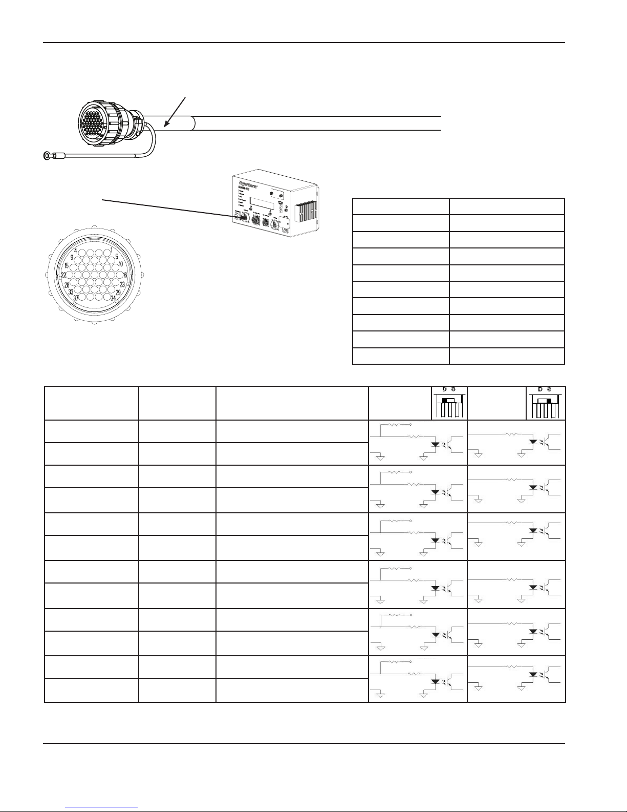
INSTALLATION
CNC I/O cable
Connect this end to the connector
on the control module with the
yellow circle.
Notes:
• All ArcGlide CNC inputs can be
• For more information about discrete
Yellow band
configured for dry contact closures
or 12 – 24 V sourced inputs.
CNC I/O signals, see ArcGlide
discrete interface signals.
Connect this end to
the CNC by adding the
appropriate connector for
your CNC.
Part number Length
223213 3.0 m (10 ft)
223214 6.0 m (20 ft)
223122 7.5 m (25 ft)
223215 10.5 m (35 ft)
223005 15.0 m (50 ft)
223107 23.0 m (75 ft)
223108 30.5 m (100 ft)
223109 45.5 m (150 ft)
223110 61.0 m (200 ft)
Pin number* Color Signal name
1 Red Cycle Start input +
2 Black Cycle Start input –
3 White Low gain input +
4 Black Low gain input –
5 Green AVC* Disable input +
6 Black AVC* Disable input –
7 Blue IHS Sync input +
8 Black IHS Sync input –
9 Yellow Spare Input 1 +
10 Black Spare Input 1 –
11 Brown Spare Input 2 +
12 Black Spare Input 2 –
Dry contact
circuit
+24 V
3.9 K
+
3.9 K
_
+
_
+
_
+
_
+
_
+
_
3.9 K
3.9 K
3.9 K
3.9 K
3.9 K
+24 V
3.9 K
+24 V
3.9 K
+24 V
3.9 K
+24 V
3.9 K
+24 V
3.9 K
Sourced
circuit
+
3.9 K
_
+
3.9 K
_
+
_
+
_
+
_
+
_
3.9 K
3.9 K
3.9 K
3.9 K
* Pin numbers are the same on both ends of the cable.
** AVC = Arc voltage control
2-42 ArcGlide THC Instruction Manual
2
Page 79

INSTALLATION
B
A
B
A
B
A
B
A
B
A
B
A
Pin number* Color Signal name
13 Orange IHS Complete output A
14 Black IHS Complete output B
15 White Retract complete output A
16 Red Retract complete output B
17 Green Machine Motion output A
18 Red Machine Motion output B
19 Blue THC Error output A
20 Red THC Error output B
21 Yellow Torch Breakaway output A
22 Red Torch Breakaway output B
23 Brown CNC Spare output A
24 Red CNC Spare output B
25 Orange Motion interlock input +**
Dry contact or sourced circuit
A
B
A
B
A
B
A
B
A
B
A
B
normally
+24 V
normally
open
normally
open
normally
open
normally
open
normally
open
open
26 Red
Motion interlock input
27 White Interlock output A
28 Green Interlock output B
29 Blue Common
30 Green Common
31 Yellow Common
32 Green Common
33 Brown +24 VDC output
34 Green +24 VDC output
35 Orange +24 VDC output
36 Not connected
37 Not connected
–**
-
A
B
normally
open
+24 V
+24 V
+24 V
* Pin numbers are the same on both ends of the cable.
** The input is closed if a jumper is used.
ArcGlide THC Instruction Manual 2-43
2
Page 80

INSTALLATION
Plasma interface I/O cable
Connect this end to
the port on the control
module with the blue
circle.
Blue band
Connect this end to the
discrete plasma interface
at the plasma system
Pins 38 – 50 are not used.
Part number Length Part number Length
223227 3.0 m (10 ft) 223103 23.0 m (75 ft)
223228 6.0 m (20 ft) 223104 30.5 m (100 ft)
223123 7.5 m (25 ft) 223105 45.5 m (150 ft)
223229 10.5 m (35 ft) 223106 61.0 m (200 ft)
223004 15.0 m (50 ft)
Note: For more information about discrete plasma I/O signals, see ArcGlide discrete interface signals.
Pin number* Color Signal name
1 Red RS422 Rx +
Dry contact
circuit
Sourced
circuit
2 Black RS422 Rx -
3 White RS422 Tx +
4 Black RS422 Tx –
5 Green RS422 common
6 Black Motion input +
7 Blue Motion input –
8 Black Error input +
9 Yellow Error input –
10 Black Rampdown error input +
11 Brown Rampdown error input –
12 Black Not ready input +
13 Orange Not ready input –
14 Black Spare input +
15 White Spare input –
+
_
+
_
+
_
+
_
+
_
3.9 K
3.9 K
3.9 K
3.9 K
3.9 K
+24 V
3.9 K
+24 V
3.9 K
+24 V
3.9 K
+24 V
3.9 K
+24 V
3.9 K
+
3.9 K
_
+
3.9 K
_
+
3.9 K
_
+
3.9 K
_
+
3.9 K
_
* Pin numbers are the same on both ends of the cable.
2-44 ArcGlide THC Instruction Manual
2
Page 81

INSTALLATION
B
A
B
A
B
A
B
A
B
A
B
A
Note: All ArcGlide CNC inputs can be congured for dry contact closures or 12 – 24 V sourced inputs.
Pin number* Color Signal name Dry contact or sourced circuit
16 Red Corner output A
17 Green Corner output B
18 Red Pierce output A
19 Blue Pierce output B
20 Red Hold output A
21 Yellow Hold output B
22 Red Start output A
23 Brown Start output B
24 Red Spare output A
25 Orange Spare output B
26 Red Remote on output A
27 White Remote on output B
28 Green Common
29 Blue Common
A
B
A
B
A
B
A
B
A
B
A
B
30 Green Common
31 Yellow +24 VDC output
32 Green +24 VDC output
33 Brown +24 VDC output
+24 V
+24 V
+24 V
34 Green 1/50 Arc voltage +
35 Orange
1/50 Arc voltage
–
36 and 37 Not connected
* Pin numbers are the same on both ends of the cable.
ArcGlide THC Instruction Manual 2-45
2
Page 82

INSTALLATION
Non-serial plasma interface cable
This cable connects the ArcGlide plasma interface PCB and control board inside the plasma system. Use this cable only
when the CNC provides serial communication directly to the control board.
red heatshrink
Part number Length Used in
223192 61 cm (2 ft) HPR130 XD, HPR260 XD
223193 2.3 m (7.5 ft) HPR400 XD
Pin number Color Signal name
1 Not connected
2 Not connected
3 Not connected
4 Not connected
5 Not connected
6 Black Motion input +
7 Blue Motion input –
8 Black Error input +
9 Yellow Error input –
10 Black Rampdown error input +
11 Brown Rampdown error input –
12 Black Not ready input +
13 Orange Not ready input –
14 Black Spare input +
15 White Spare input –
2-46 ArcGlide THC Instruction Manual
2
Page 83

Pin number Color Signal name
16 Red Corner output A
17 Green Corner output B
18 Red Pierce output A
19 Blue Pierce output B
20 Red Hold output A
21 Yellow Hold output B
22 Red Start output A
23 Brown Start output B
24 Red Spare output A
25 Orange Spare output B
INSTALLATION
26 Red Remote on output A
27 White Remote on output B
28 Green Common
29 Blue Common
30 Green Common
31 Yellow +24 VDC output
32 Green +24 VDC output
33 Brown +24 VDC output
34 Green 1/50 Arc voltage +
35 Orange
36 and 37 Not connected
1/50 Arc voltage
–
ArcGlide THC Instruction Manual 2-47
Page 84
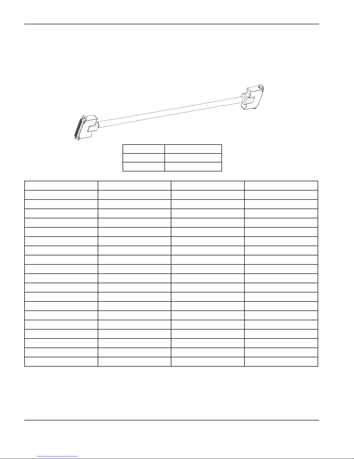
INSTALLATION
Serial plasma interface cable
This cable connects the ArcGlide plasma interface PCB and control board inside the plasma system. Use this cable
when serial communication is supplied to the plasma system by the ArcGlide THC.
Part number Length
123760 61.0 cm (2 ft)
123209 1.5 m (5 ft)
Pin number Signal Pin number Signal
1 HPR RX – 20 HPR Rx +
2 HPR TX – 21 HPR Tx +
3 RS422 Com 22 HPR powered on
4 Ground 23 Motion
5 Ground 24 Error
6 Ground 25 Rampdown error
7 Ground 26 HPR NR
8 Not connected 27 Not connected
9 Not connected 28 Not connected
10 Not connected 29 Not connected
11 Not connected 30 Not connected
12 Corner A 31 Corner B
13 Pierce A 32 Pierce B
14 Hold A 33 Hold B
15 Plasma station relay A 34 Plasma station relay B
16 Rem on A 35 Rem on B
17 Not connected 36 Ground
18 Ground 37 HPR plasma
19 Not connected 38 Ground
2-48 ArcGlide THC Instruction Manual
2
Page 85
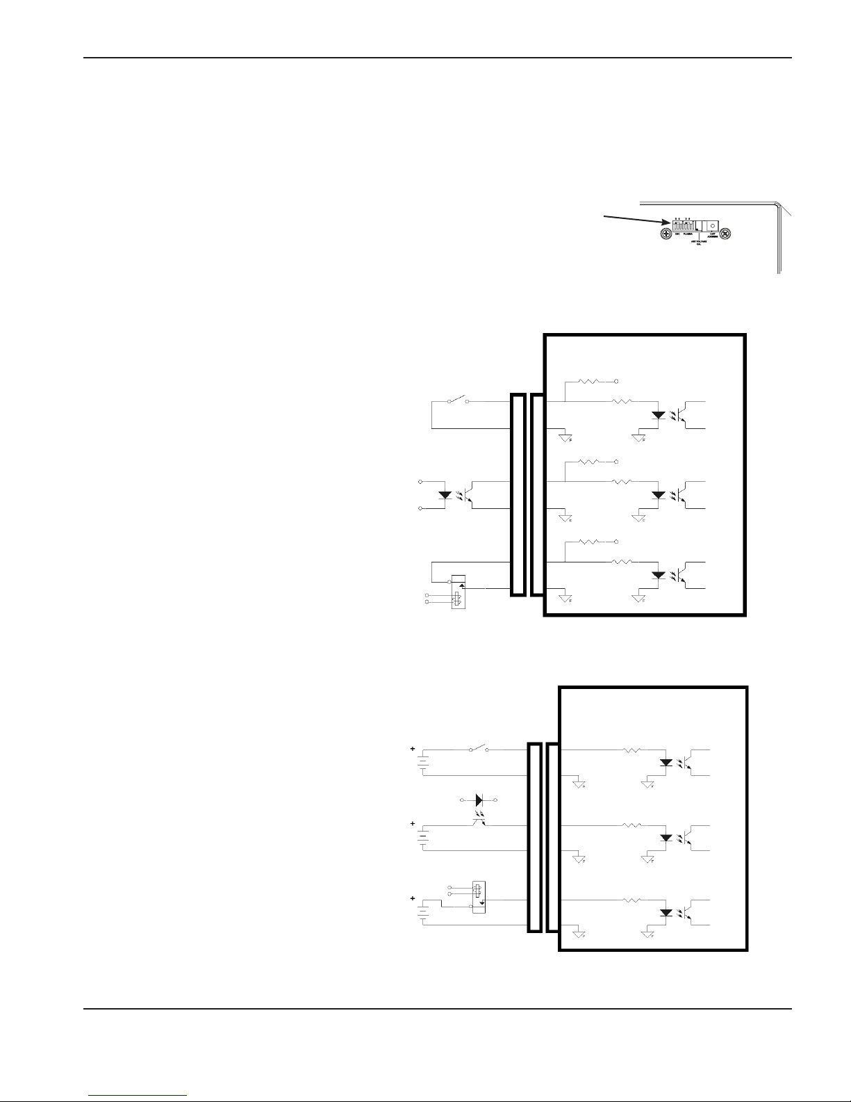
INSTALLATION
ArcGlide discrete interface signal examples
Inputs
The figures below show simplified schematics of the ArcGlide THC inputs. The inputs for both CNC and plasma can be
configured for dry contacts (no external voltage), the default, or for positive voltage sourced inputs. The inputs have two
different modes that are selected using switches behind the calibration and setup door on
the top right front of the control module.
The mode that is selected automatically compensates for the polarity reversal so that in both
cases a closed switch input will activate the signal.
All inputs to the lifter interface and operator console interface are fixed in the dry contact
mode.
ArcGlide internal circuitry
3.9 K
+24 V
+24 V
+24 V
Switch
Optoisolator
Relay
+
–
3.9 K
3.9 K
+
–
3.9 K
3.9 K
+
–
3.9 K
Dry contact inputs
ArcGlide internal circuitry
Switch
12 VDC to 24 VDC
12 VDC to 24 VDC
12 VDC to 24 VDC
(external supply)
+
3.9 K
–
+
3.9 K
–
+
3.9 K
–
Voltage sourced inputs
ArcGlide THC Instruction Manual 2-49
2
Page 86

INSTALLATION
Outputs
Most of the ArcGlide THC outputs are relay contacts and can be used for either AC or DC loads. All relay outputs are
protected with automatically resetable thermal fuses that protect against currents above 100 mA. The 24 V supply
is limited to a total of 2 Amps for all outputs. The figure below shows the simplified schematic of the ArcGlide THC
outputs.
ArcGlide internal circuitry
+24 V Field
Relay
Relay
Relay
PTC* 100 mA
PTC* 100 mA
PTC* 100 mA
*Positive Temperature Coefficient
A
B
Resistors
A
B
A
B
Relay outputs
Use internal field +24 VDC
LED
Optoisolator
+12 VDC to 24 VDC
(external supply)
Relay
Voltage 12 V to
24 VAC or VDC
2-50 ArcGlide THC Instruction Manual
Page 87
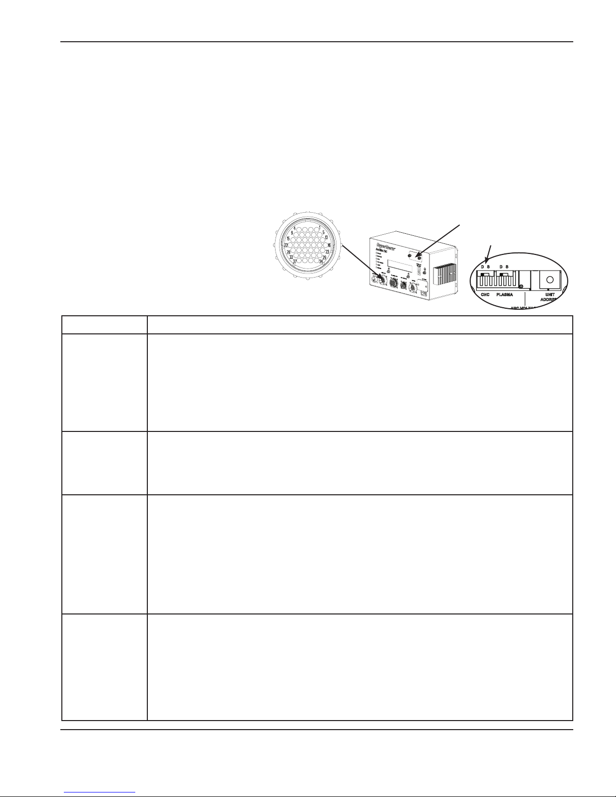
INSTALLATION
CNC discrete I/O
All the required discrete interface signals between the control module and the CNC are marked with asterisks (*) in the
following table. All other signals are optional for multiple torch operation, improved performance, or reduction in cycle
times. The inputs have two different modes that are selected using switches behind the calibration and setup door. The
inputs can be configured for dry contacts (no external voltage), or for positive voltage sourced inputs.
If the THC controller interface is configured with dry contacts, the operation of LEDs on the discrete plasma interface is
reversed and the LEDs turn OFF when input is active. With sourced inputs, LEDs turn ON when an input is active.
Note If the Hypernet interface to the CNC is used, only the Interlock Input signal must be wired on this
connector. If discrete signals are used, the required discrete signals on this connector must be connected.
Calibration and setup door
Dry or sourced input
switch
This connector has a
yellow ring.
CNC I/O Description
Cut Control*
Low Gain Input
Torch Height
Disable*
Hold Ignition
This is a required signal. It is an output from the CNC and an input to the ArcGlide. The CNC
should activate this signal to begin a plasma cut. This signal begins the entire process of IHS,
Plasma Start and Motion, and Automatic Voltage Control (AVC) followed by a retract at the end of
the cut when this signal is removed. This signal must be maintained during the plasma cut.
This input automatically reduces the AVC gain for marking. This improves the stability of the height
control during marking
This is an optional signal input to the ArcGlide. When active this signal will temporarily disable
the automatic height control and force the torch to hold its height position. It is primarily used to
disable the height control in corners or whenever the machine speed is not at the optimal cutting
speed. This signal improves cutting performance by disabling the height control when the machine
slows down for corners. This improves the corner cut quality and prevents the torch from diving
into the workpiece.
This is an optional input to the ArcGlide to allow multiple torches to start synchronized. For a
single torch installation, this signal is optional but recommended. The CNC should activate this
signal to delay plasma torch ignition until all active torches in a multiple torch configuration have
completed their IHS sequence and are in position and ready to fire. At this point all active torches
will return an active IHS Complete signal to the CNC and the CNC should remove all Hold
Ignition input signals and allow all active plasma torches to ignite simultaneously.
ArcGlide THC Instruction Manual 2-51
Page 88

INSTALLATION
CNC I/O Description
Spare inputs 1
and 2
IHS Complete
Retract Complete
Cut Sense*
These are unused inputs to the ArcGlide that are available for future use.
This is an optional signal output from the ArcGlide to the CNC. This signal is used to indicate that
the Initial Height Sensing (IHS) is complete and that the torch is in position and ready to fire. For
multiple torch installations the CNC should wait for all active torches to return an IHS Complete
signal before simultaneously removing the Hold Ignition signal and allowing all torches to ignite at
the same time. For single torch installations this signal is not used.
This signal is an output from the ArcGlide that is active when a cut is completed and the torch has
been raised to the selected Retract Height. The CNC uses this signal to delay the move to the
next cut and to clear any tip-ups. This signal is optional.
This is a required output from the ArcGlide to the CNC. This signal is issued after plasma torch
ignition and the Pierce Delay Time has expired. This signal indicates that the CNC should begin
the cutting motion.
For more information on Pierce Delay, see the Operation section.
This is an output from the ArcGlide to the CNC that indicates that the THC has encountered an
THC Error
Breakaway Error
Interlock Input*
Interlock Output The state of this independent contact closure is the same as the state of the Interlock Input.
error condition. The HMI displays the actual error condition.
For more information on ArcGlide error messages, see the Maintenance section.
This output from the ArcGlide indicates that the torch breakaway has separated. This output is
reset by replacing the torch breakaway.
This is a normally closed contact closure that allows ArcGlide motion. If this contact is opened,
the ArcGlide lifter motor drive will lose power. This circuit must be wired according to national and
local regulations.
2-52 ArcGlide THC Instruction Manual
Page 89
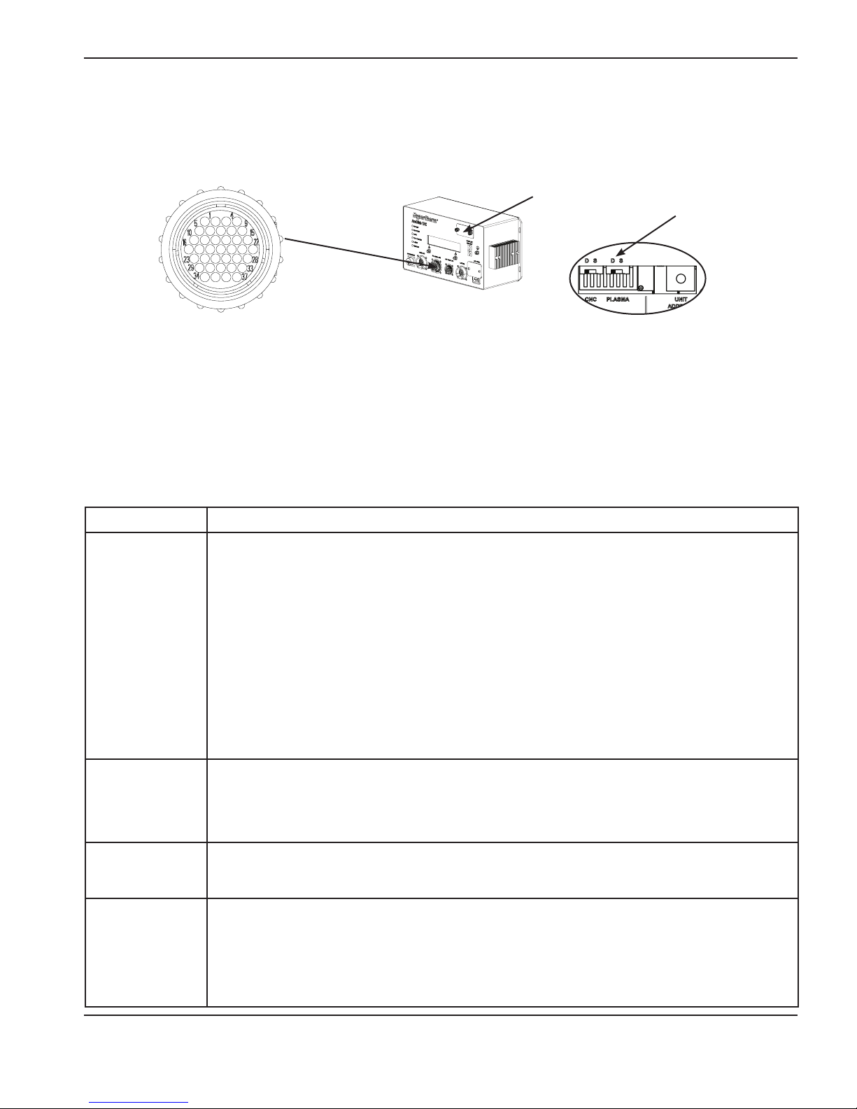
INSTALLATION
Plasma discrete I/O
All the required discrete interface signals between the control module and the plasma system are marked with asterisks
(*) in the following table. All other signals are optional for multiple torch operation, improved performance, or reduction in
cycle times.
Calibration and setup door
Dry or sourced input switch
This connector
has a blue ring
The inputs have two different modes that are selected using switches behind the calibration and setup door. The inputs
can be configured for dry contacts (no external voltage), or for positive-voltage sourced inputs. The following discrete
signals are used to connect the ArcGlide THC to the plasma system if the Hypernet interface is not used.
Notes: If the THC controller interface is configured with dry contacts, LED operation on the discrete plasma
interface is reversed and the LEDs will turn OFF when input is active.
If the plasma system uses the Hypernet Interface for communication with the ArcGlide, these discrete
signals are not used. If discrete signals are used, the required signals of this connector must be
connected.
Plasma I/O Description
This is an optional signal path that provides the serial interface to the HPR power supplies. If
connected to an HPR auto gas system then all plasma related parameters can be set using this
interface. For both HPR auto and manual systems this interface can be used to get information on
the plasma system status and errors.
RS422
Arc Transfer*
Plasma Error
Note: The ArcGlide THC does not support the HPR serial protocol. It only relays the data
sent from the CNC through the Hypernet interface to the plasma system. Any data
received from the plasma system over the RS422 serial is then relayed to the CNC
through the Hypernet interface. It is the responsibility of both the connected CNC
and HPR plasma to fully support the serial protocol used.
This is a required input to the ArcGlide. This signal is input to the ArcGlide from the plasma
system to indicate that arc transfer has occurred.
This is an optional signal that is output from the plasma system to indicate that an error has
occurred.
This is an optional output from the plasma system that indicates the plasma torch lost arc
Rampdown Error
transfer before the controlled arc turn off. This condition indicates that the consumable life may
be reduced. The user is encouraged to make any changes to the part programming to reduce or
eliminate these types of errors to achieve optimal consumable life.
ArcGlide THC Instruction Manual 2-53
Page 90

INSTALLATION
Plasma I/O Description
This is an optional output from the plasma system that indicates that the plasma system is not
Not Ready
Corner
Spare Input This is an extra input for future use.
Pierce
ready to receive a Plasma Start. The plasma system may be busy changing or purging gas flows
or be involved in some other time consuming operation. To insure proper operation the CNC
should check this signal before issuing a Plasma Start.
This is an optional output from the THC to the plasma system. This signal indicates that the
plasma system should reduce its output current to a pre-programmed level to improve the cutting
performance in corners. The default value is 50% of the normal cutting current.
This is an optional output from the THC and input to HPR supplies. This signal informs the
plasma system that the unit is piercing and the plasma system should maintain the high shield
gas preflow during the pierce. This signal is used to improve the piercing capability of HPR power
supplies only.
This is an optional output from the THC and input to the plasma system. For a single torch
installation, this signal is optional but recommended. The CNC should activate this signal to delay
plasma torch ignition until all active torches in a multiple torch configuration have completed their
Hold
IHS sequence and are in position and ready to fire. At this point, all active torches will return
an active IHS Complete signal to the CNC and the CNC should remove all Hold Ignition input
signals and allow all active plasma torches to ignite simultaneously. This signal can also be used
to save cycle time by performing gas preflow during the IHS sequence.
This output from the THC is used to start the plasma system. This signal is a maintained signal.
Start*
The plasma system will continue to power the plasma cutting torch until this signal is removed.
When the Start signal is removed the plasma system begins to ramp down and turn off the torch
power.
Spare Output This is an extra output for future use.
This is an optional output signal from the ArcGlide THC that can be used to power up or down
capable plasma power supplies. On capable systems, such as the HPR plasma supplies,
Remote On
deactivating this signal will remove the high power input to the plasma system and will turn off the
gas and torch cooling pump. For more information, see Hypernet plasma interface (141161) in
the Maintenance section.
This analog input to the THC provides the arc voltage feedback used for automatic height control.
1/50th Arc
Voltage
The signal is scaled so that 5 volts DC equals an arc voltage of 250 volts DC. The positive side of
this voltage should be connected to chassis ground. To provide high accuracy this voltage should
have an effective output resistance of 2 K Ohms or less.
2-54 ArcGlide THC Instruction Manual
2
Page 91

INSTALLATION
Optional operator console discrete I/O
The following discrete signals are used between the control module and the optional, customized operator console.
This connector
has a green ring
Operator
console I/O
Manual Disable
Switch
Manual Select
Switch
Torch UP Switch
Description
When this switch is active, its contact input signal indicates that the cutting station connected
to this THC is disabled and will not operate when an active Cut Control command is issued from
the CNC. If the plasma system is capable of remote power down, then it will be powered down
whenever this disable switch is active. When neither the Manual Disable nor Manual Select inputs
are active, the CNC can select the individual stations under program control.
This switch’s contact input signal indicates that the connected station will be manually forced into
the active state and will operate when an active Cut Control command is issued from the CNC.
When the Manual Disable or Manual Select inputs are inactive, the CNC can select the individual
stations under part program control.
This is a switch contact input signal that raises the torch. This input raises the torch manually
if the torch is not cutting. The manual motion starts as a 0.01-inch jog; after a 1/2 second, the
motion remains at the slow speed. After an additional second, the motion accelerates to the
intermediate programmed speed. If the torch is in the process of cutting, this input increases the
voltage set point at a rate of 0.2 volt every 1/4 second.
This is a switch contact input signal that can be used to lower the connected torch. This input
Torch DOWN
Switch
will cause the torch to lower manually. The manual motion starts as a 0.01-inch jog; after a
1/2second, the motion remains at the slow IHS speed. After an additional second, the motion
accelerates to the intermediate programmed speed. If the torch is in the process of cutting, this
input decreases the voltage set point at a rate of 0.2 volt every 1/4 second.
ArcGlide THC Instruction Manual 2-55
Page 92
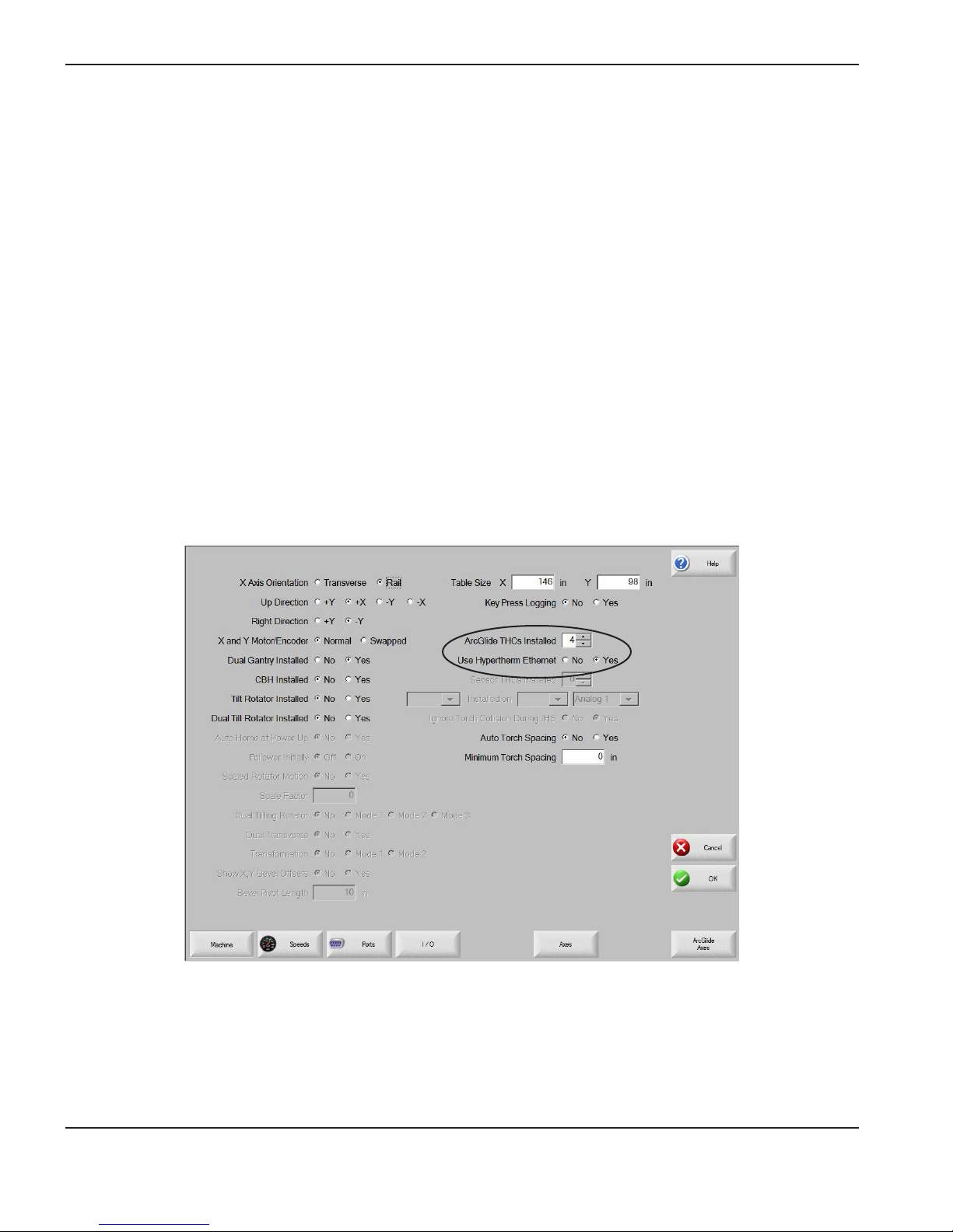
INSTALLATION
ArcGlide software setup
If you are installing the ArcGlide THC hardware with a Hypertherm CNC and Phoenix® software (version 9.5 or later)
and the Hypernet interface, refer to Phoenix Software Installation and Setup Manual for complete information.
Select ArcGlide and Hypertherm Ethernet
To select the ArcGlide THC and Hypernet:
1. Select Setups > Password and enter the Machine password.
2. On the Machine setup screen,use the scroll box next to ArcGlide THCs Installed to specify the number of ArcGlide
THCs you are configuring.
3. Select Yes next to Use Hypertherm Ethernet to configure the system for Hypernet communication. Select No to
configure the system for discrete communication.
ArcGlide THC parameters in the Machine setup screen in Phoenix software
2-56 ArcGlide THC Instruction Manual
2
Page 93
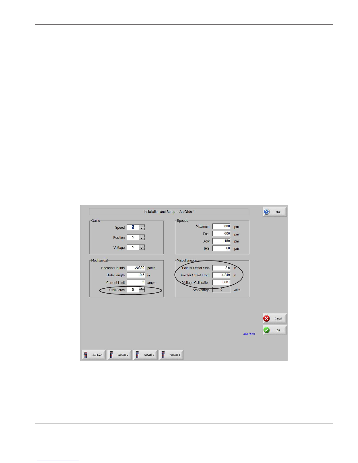
INSTALLATION
ArcGlide axes
Use the setup parameters on the ArcGlide axes screens to verify that the THC operates successfully for your
application.
To view ArcGlide axis setup parameters:
1. On the Machine Setup screen, select ArcGlide Axis > ArcGlide. If you have installed more than one ArcGlide
axis, the screen displays a numbered soft key for each axis.
2. Press or click the soft key for the ArcGlide axis you want to set up. Use the information in the table in this section to
set values for the parameters on the ArcGlide axes screens.
3. Click OK when you have nished setting up each axis.
The default values for each parameter on the ArcGlide axes screens are optimized for the majority of applications.
However, the following parameter values may need to be adjusted:
• Stall Force
• Pointer Offset Side
• Pointer Offset Front
• Voltage Calibration
ArcGlide Axes Setup screen in Phoenix software
ArcGlide THC Instruction Manual 2-57
2
Page 94

INSTALLATION
ArcGlide THC ports
To assign ports for the ArcGlide THC:
1. Verify that the ArcGlide setup fields are correct in the Machine setup screen. See Select ArcGlide and Hypertherm
Ethernet for more detail.
2. Select Setups > Password and enter the Station password.
3. Click Reset if ArcGlide THC does not appear in the Lifter dropdown list.
4. On the Station Configuration screen, select ArcGlide THC for each station on which you want to configure an
ArcGlide THC.
5. Click OK when you have nished assigning ArcGlide ports.
Note: The number of the station must correspond to the Hypernet address on any ArcGlide component that is
connected to Hypernet.
ArcGlide Station Configuration screen in Phoenix software
2-58 ArcGlide THC Instruction Manual
2
Page 95

INSTALLATION
ArcGlide setup parameters
Speed Gain
Description: This gain value regulates the speed of the lifter.
When to use: Optimize the Speed Gain value before attempting to change either the Position or Voltage gains.
How to use: Regulated speed moves are used for manual moves and for approaching the workpiece for automatic
IHS operation.
For the standard Hypertherm lifter, the value of 5 is appropriate. If this value is set too high, the lifter
speed regulation will become unstable and prone to oscillation. If this value is set too low, the speed
regulation can become slow and inaccurate. This value can be tested by repeatedly raising and
lowering the lifter in Manual Mode.
To optimize this gain, raise this value until a very slight oscillation is detected during manual operation
and then reduce the setting by one.
Range: 1 to 10, the default setting = 5
Position Gain
Description: This gain is used for closed loop positioning.
When to use: Adjust the Position Gain after the proper Speed Gain has been determined.
Position-based moves are used for moving to the IHS height and to the retract height at the end of
the cut.
How to use: For the standard Hypertherm lifter the value of 5 is appropriate. If this value is set too high, the lifter
positioning will become unstable and prone to oscillation. If this value is set too low, the positioning
can become slow and inaccurate.
This gain can be tested by repeatedly executing IHS TEST and checking that the lifter quickly and
accurately reaches the IHS and Retract Heights.
To optimize this gain, raise the value until a very slight oscillation is detected when settling into the
IHS or Retract positions and then reduce the setting by one.
Range: 1 to 10, the default setting = 5
Voltage Gain
Description: This gain is used when the THC is operating closed-loop arc voltage control.
When to use: Adjust the Voltage Gain after the proper Speed Gain has been determined
How to use: If this value is set too high, the lifter positioning during closed-loop arc voltage control will become
unstable and prone to oscillation. If this value is set too low, the arc voltage control can become slow
and inaccurate. For the Hypertherm 24.13-cm (9.5-inch) lifter, the value of 5 is appropriate.
The Voltage Gain can be tested by repeatedly performing a test cut under closed-loop arc voltage
control and checking that the THC quickly and accurately reaches the set arc voltage.
To optimize this gain, raise this value until a very slight oscillation is detected during a cut and then
reduce the setting by 1 or 2.
Range: 1 to 10, the default setting = 5
ArcGlide THC Instruction Manual 2-59
Page 96

INSTALLATION
ArcGlide setup parameters (continued)
Encoder Counts per Inch
Description: This value scales the position feedback.
When to use: During installation.
How to use: The value is based on the ball-screw pitch and the encoder resolution, it is equal to the number of
encoder counts per revolution multiplied by the number of revolutions required to travel one inch. The
encoder is operated in (4X) mode so the number of counts per revolution is equal to the number of
pulses per revolution multiplied by four.
The value used for the Hypertherm 24.13-cm (9.5-inch) lifter is 20,320 counts per inch. The
Hypertherm 24.13-cm (9.5-inch) lifter has an encoder with 1,000 pulses per revolution which
produces 4,000 counts per revolution in 4X mode. The Hypertherm 24.13-cm (9.5-inch) lifter has a
5 mm pitch ball-screw which requires 25.4 (in/mm) / 5 (mm) = 5.08 revolutions to travel one linear
inch. This results in a value of 5.08 (revolutions) x 4,000 (counts/revolution) = 20,320 counts per
linear inch of travel.
Example: 20,320 counts per linear inch.
Slide Length
Description: This value is the length of the lifter’s usable travel.
When to use: During installation.
How to use: The ArcGlide lifter has 9.45 inches of usable travel.
Example: 9.45 inches
Current Limit
Description: This is the maximum continuous motor current for which the lifter motor is rated.
When to use: During installation.
How to use: This value may be periodically exceeded for a couple of seconds during extreme acceleration but it
is used as the normal continuous operating current limit. The Hypertherm 24.13-cm (9.5-inch) lifter
uses a motor with a 3 Amp continuous current limit.
The motor can be damaged if the value for this parameter is set above the continuous current
operating limit for the installed motor.
Range: 1 to 6 Amps, the default setting = 3 Amps
2-60 ArcGlide THC Instruction Manual
Page 97

INSTALLATION
ArcGlide setup parameters (continued)
Stall Force*
Description: This value determines the amount of force used for the Stall Force backup to the normal Ohmic plate
sensing.
When to use: During installation and possibly when cutting thin material.
How to use: The values are relative values and start at 1 for the minimum force and 10 for the maximum force. This
value should be set high enough to avoid false stall detection but not so high that the excess force
causes a deflection of the workpiece and inaccurate IHS operation.
With the Hypertherm 24.13-cm (9.5-inch) lifter, the value of 5 is appropriate. It may be necessary to
reduce this value if the THC is used with a thin workpiece. Use the Test IHS function to optimize this
value.
Test this feature by disabling the Ohmic contact either by using the process menu or by removing the
Ohmic contact wire. The Stall Force value is optimum when there are no false workpiece detections
and the IHS operation is relatively accurate.
Range: 1 to 10, the default setting = 5
Voltage Calibration*
Description: This value is used to finely calibrate the measured arc voltage accuracy.
When to use: This parameter is not normally required. It can be used for fine tuning in multiple ArcGlide installations
or for long leads.
How to use: The measured input value is multiplied by the value of this parameter before being used for either
voltage control or display. To determine this value, measure the raw arc voltage. If the arc voltage in
the display is different, divide the raw arc voltage by the value in the display and enter the result as the
value for this parameter. For example, if the raw arc voltage is 120 and the value in the display is 125,
divide 120 by 125, the result, 0.96 would be the value for the Voltage Calibration parameter.
This calibration affects all of the ArcGlide hardware connected to this station including the HMI
display and the HPR Hypernet interface. When an ArcGlide is shipped from the factory, the voltage
has been calibrated in hardware and this value is set to (1.000). This parameter is normally only used
to adjust for the exact same arc voltage displays on multiple ArcGlide installations.
Range: 0.900 to 1.100, the default setting = 1.000
Arc Voltage Display
Description: This Arc Voltage value is for display only and cannot be edited. It is provided to check the results after
you change the Arc Voltage Calibration above.
When to use: During arc voltage calibration
How to use: This parameter is used for display only.
Range: 0 to 400
* Asterisks indicate values that may need to be adjusted.
ArcGlide THC Instruction Manual 2-61
Page 98

INSTALLATION
ArcGlide setup parameters (continued)
Maximum Speed
Description: This parameter sets the maximum linear speed that the THC can achieve.
This value depends on the lifter motor speed at 45 VDC, the screw pitch, the weight of the lifter load,
and the desired speed of operation. This value is used as the 100% speed value when scaling the
control equations. It is important that this value is set correctly because it affects the scaling of all the
other control loops.
When to use: During installation. Set this parameter before optimizing Speed Gain.
How to use: Set this value to a speed that can be achieved easily. Use a conservative setting assuming low
incoming AC line voltage. If this speed is set too high, the maximum available motor drive voltage will
be insufficient to drive the motor to the desired maximum speed. This will make the top of the linear
control range unavailable and result in sub-optimal operation. If the Maximum Speed is set too high, it
may be difficult for the THC to operate precisely at slow speeds when trying to control the arc voltage
or position to an accurate IHS distance. If this speed is set too low, the linear control range will only
cover the low portion of the available mechanics range and the result will be sub-optimal.
For the Hypertherm 24.13-cm (9.5-inch) lifter, this value is 0.1524 centimeters (600 inches) per
minute. At the low input line voltage limit, the motor drive is capable of supplying about 45 VDC. The
motor used in the Hypertherm 24.13-cm (9.5-inch) lifter will produce full rated torque at about 3,300
RPM driven by this voltage. The Hypertherm 24.13-cm (9.5-inch) lifter has a 5mm pitch ball-screw
which requires 25.4 (in/mm) / 5 (mm) = 5.08 revolutions to travel one linear inch. This results in a
value of 3,300 (RPM) / 5.08 (revolutions/inch) = 650 linear inches per minute (IPM) of travel speed.
This value was rounded down to the nearest even hundreds to guarantee a 100% value under all
conditions.
Example: 600 IPM
Fast Speed
Description: This speed is used for all automatic rapid moves such as the End-of-Cut-Retract or the Initial
Approach to the workpiece.
When to use: During installation.
How to use: This parameter is usually set equal to the value of Maximum Speed but it can be set lower if there is a
heavy load on the lifter.
With the Hypertherm 24.13-cm (9.5-inch) lifter this value is set to 600 IPM.
Example: 600 IPM
Slow Speed
Description: This speed is the Homing Speed and is the fastest speed used for manual moves. It is also the
maximum speed limit used during arc voltage control.
When to use: During installation
How to use: With the Hypertherm 24.13-cm (9.5-inch) lifter this value is set to 150 IPM.
Example: 150 IPM
2-62 ArcGlide THC Instruction Manual
Page 99

INSTALLATION
ArcGlide setup parameters (continued)
IHS Speed
Description: This parameter sets the slow speed for the final approach to the workpiece during an IHS operation. It
is also used as the slow speed for manual moves.
When to use: During installation.
How to use: With the Hypertherm 24.13-cm (9.5-inch) lifter, this value is set to 60 IPM. To avoid poor speed
regulation, do not set this value below 10% of Maximum Speed.
Example: 60 IPM
Pointer Offset Side*
Description: This value is the offset distance between the torch center and the laser pointer when looking from the
side of the cutting machine.
When to use: During installation.
How to use: Use the precise distance between the laser spot and the center of the torch to fine tune this value.
Example: 6.6 cm (2.600 inches)
Pointer Offset Front*
Description: This value is the offset distance between the torch center and the laser pointer when looking from the
front of the cutting machine.
When to use: During installation
How to use: Use the precise distance between the laser spot and the center of the torch to fine tune this value.
Example: 11 cm (4.249 inches)
* Asterisks indicate values that may need to be adjusted.
ArcGlide THC Instruction Manual 2-63
Page 100

INSTALLATION
2-64 ArcGlide THC Instruction Manual
 Loading...