

Page 1

Introduction
Hypertec ISDN 10T Router
USER'S MANUAL
Information in this document is subject to change without
notice. All rights reserved. All brand names are registered
trademarks of their respective companies.
1
Page 2

Introduction
WARNING
This equipment generates, uses, and can radiate radio frequency energy and, if not installed and used in
accordance with the instruction manual, may cause interference to radio communications. It has been
tested and found to comply with the limits for a Class A computing device pursuant to Subpart J of Para.
15 of FCC Rules, which are designed to provide reasonable protection against such interference when
operated in a commercial environment. Operation of this equipment in a residential area is likely to cause
interference in which case the user at his own expense will be required to take whatever measures may be
required to correct the interference.
NOTICE
The information contained in this manual is subject to change without notice
No warranty is made of any kind with regard to this material, including but not restricted to, the implied
warranty of fitness for a particular purpose. The vendor shall not be liable for errors contained herein or
for incidental or consequential damages in connection with the furnishing, performance or use of this
material.
Windows, Windows95, and Windows NT are trademarks of Microsoft Corporation
All rights reserved
2
Page 3

Introduction
Contents
Contents 3
1 INTRODUCTION 1-1
About this Manual 1-4
2 INSTALLATION 2-1
General 2-1
Hardware Installation 2-1
Software Installation 2-3
Installing EasyWeb 2-4
3. Concepts and Principles of Operation 3-1
ISDN Overview 3-1
Data Communication Services 3-3
Voice Communication Service 3-15
Basic Rate ISDN Provisioning for United States and Canada 3-15
4. Configuration and Management 4-1
Introduction 4-1
NMS 4-2
Monitoring Sta tus with ClearMon. 4-40
Managing the HyperRoute from a Console 4-40
Managing the HyperRoute from a Browser 4-42
5. Troubleshooting 5-1
Troubleshooting Tips 5-1
Index 6
3
Page 4

Introduction
INTRODUCTION
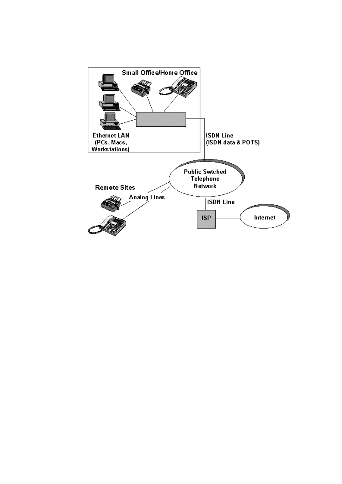
The Hypertec ISDN 10T Router is a compact router/bridge designed for small office and home
applications by providing a consolidated data and voice link to Internet, Intranet, and the telephone
network over a single ISDN line.
Figure 0-1 The Hypertec ISDN 10T Router
The Hypertec ISDN 10T Router provides an ideal means of connecting a local area network consisting of
Ethernet stations to the Internet through a local Internet Service Provider (ISP) and using conventional
voice and fax services over the same ISDN line.
Using the Hypertec Router, users at Ethernet workstations can communicate freely with each other over a
private Intranet and can access Internet servers all via the same ISDN line. The Hypertec Router
establishes the ISDN connection when required and automatically drops when it is not in use. The
Hypertec ISDN Router is of equal value in linking satellite branches with Novell IPX b ased networks to
their head office Novell Networks, using IPX spoofing to minimise call connection time.
By using up to 128 KBPS bandwidth of an ISDN digital line, the Hypertec ISDN Router overcomes the
slow response times, noise and data corruption which may be exhibited by modems using analog lines.
The Hypertec ISDN Router includes all the hardware and software necessary for accessing the Internet
and corporate LANs.
The Hypertec ISDN Router includes full management capabilities, which permit easy configuration o f the
router and ISDN parameters. Management may be performed from a console, through SNMP network
management software, or through a web browser.
4
Page 5
Introduction
A schematic of how the Hypertec ISDN Router is used is shown in Figure 0-2 A Hypertec ISDN Router
Application.
Figure 0-2 A Hypertec ISDN Router Application
The Hypertec ISDN Routersupports the following features:
ISDN
• U or ST interfaces
• Switched ISDN service for various switches worldwide :
National ISDN, ATT 5ESS, DMS switches in North America
EuroISDN(ETSI) switches in Europe
NTT switches in Japan
EuroISDN switches in Tai wan, Singapore
ATT 5ESS switches in Korea
• Detailed accounting including dialed numbers, disconnect causes, frame statistics
• Auto Dial-out triggered by outgoing LAN traffic, auto disconnect due to inactive connection
• Bandwidth-On-Demand, 0<->1<->2 bandwidth management,1B to 2B if traffic increases
beyond threshold,. 2B to 1B if traffic falls below threshold, 1B to 0B if traffic is idle for more
than an pre-defined period
Ethernet
• 4 port Ethernet Repeater with unlimited LAN users
Internet/Intranet
• PPP, MultiLink PPP (MLPPP), LCP, IPCP, IPXCP, and BCP
• Internet and Intranet connection profiles. Allows one B channel for Internet connection and the
other B channel for intranet connection
• STAC LZS data compression with 128 KPBS -> 512 KBPS, 4:1 compression ratio on normal
text file
• Static or dynamic IP address assignment
• Static or dynamic IP Route
5
Page 6

Introduction
Security
• CLID (caller ID)
• Call-Back (hang-up and dial the caller)
• PAP/CHAP ( PPP authentication protocol)
• Access List (filtering of packets bases upon IP address)
• NAT (network address translation). Hides internal IP addresses from outside world, no need to
change existing IP address assignments, allows the subscription of single IP address account for
the entire LAN.
Network Management
• From local console, NMS/SNMP or Web Browser/HTTP
• NMS runs on Windows 3.1, Windows95 and Windows NT platforms
• Alarm warning o n ISDN usage
• Configuration file save and restore
Analog Services
• 2 RJ-11 ports for telephone, modem or fax analog devices
Router Software
• Software up graded throug h TFTP and stored in FLASH memory
6
Page 7

Introduction
About this Manual
Chapter 2, Installation. This chapter provides details of how to install the Hypertec ISDN Router
hardware and software. Guidance is provided about the ISDN line that is required from your telephone
company and the personal computer requirements to use the Network Management System software.
Chapter 3, Concepts and Principles of Operation. This chapter covers the concepts and principles of
operation of three major topics : ISDN, Data Services, and voice services. The Hypertec ISDN Router
operation principles in the area of Internet/Intranet profiles, and bandwidth management are discussed in
detail. This chapter also includes information about ISDN line provisio ning.
Chapter 4, Set-up and Configuration. This chapter provides details of how to setup and configure your
Hypertec ISDN Router for operation. This chapter provides brief details of how to perform this from a
console or from a Browser. Full details are provided for the recommended method of setup and
configuration from the NMS software provided with the Hypertec ISDN Router.
Chapter 4, Troubleshooting. This chapter provides troubleshooting procedures in the unlikely event that
Hypertec ISDN Router does not function properly.
An index is provided at the end of the manual.
Hypertec ISDN 10T Router Packing List:
Your Hypertec ISDN 10T Router should contain the following:
• The Hypertec ISDN 10T Router
• Diskette : NMS software
• Express Route Manual
• ISDN Cable: RJ45!Black color, 4 copper wire with different color, 6 feet"RJ45
• DB cable: DB9 female!1.4meter "DB9 male
• DB converter: DB9 male !"DB 25 female
• Power Adapter: Output rate at 15DVC 600mA
7
Page 8
Installation
INSTALLATION
General
The Hypertec ISDN 10T Router is shipped in a box, which contains the following items:
• The Hypertec ISDN 10T Router
• One Power Adapter with cable
• One ISDN cable, 6 foot long with an RJ45 connector at each end
• One data cable with a DB9 connector at each end
• One changer DB9 (male) to DB25 (female)
• Two 3
• One 3
1
/2” diskette containing the Hypertec ISDN 10T Router NMS software
1
/2” diskette containing the Hypertec ISDN 10T Router EasyWeb software
• This Hypertec ISDN 10T Router user manual
Check the contents of the box and ensure that everything is included. If there are any items that are
missing or appear to be damaged, replace all the items back in the box and contact your sales
representative.
Hardware Installation
Before installing the hardware, you will need:
A 100 to 230 VAC wall outlet within a few feet of where you intend to place the Hypertec ISDN
10T Router.
An ISDN BRI line RJ45 termination within a few feet of where you intend to place the Hypertec
ISDN 10T Router.
If you intend to connect an analog modem, telephone or fax to your Hypertec ISDN 10T Router,
you will need a standard RJ11 telephone cable for each of the connected devices.
Each Ethernet LAN connection to the Hypertec ISDN 10T Router must use a normal straight
through twisted pair cable with an RJ45 connector. If the LAN employs coaxial cable, an adapter
converting the coaxial cable to a twisted pair RJ45 cable must be used.
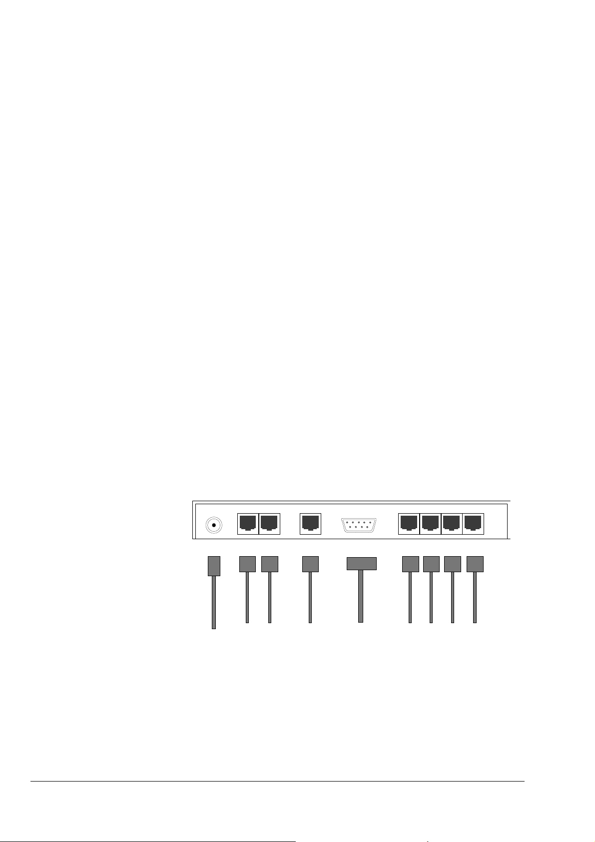
All connections during the hardware installation are made at the Hypertec ISDN 10T Router rear
panel shown in Figure 0-1, Hypertec ISDN 10T Router Rear Panel.
Power Phone1
DIN RJ 11 RJ 45 DB 9 RJ 45
Phone2
ISDN
Console
Ethernet
Power
Cord
To FAX or
Telephone
Lines
To ISDN
Line
To PC or Terminal
Console
To Ethernet Hubs
or Stations
Figure 0-1, Hypertec ISDN 10T Router Rear Panel
1
Page 9
Installation
1. Determine the place where the Hypertec ISDN 10T Router is to reside, it is designed to rest on a
flat level surface such as a desktop or table. Make sure that an AC power source and the ISDN
termination are nearby.
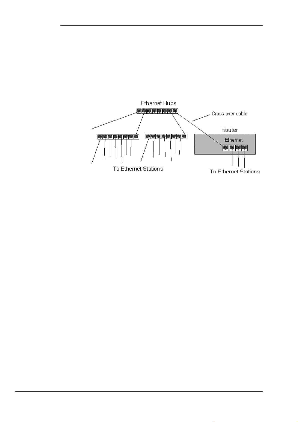
Connect the Ethernet LAN to any or all of the four RJ 45 ports labeled Ethernet using cables
with RJ45 connectors. You may daisy-chain the Hypertec ISDN 10T Router embedded repeater
to other external Ethernet hubs to accommodate more than 4 LAN users by using a cross-over
RJ45 cable (see Figure 0-2, Using Ethernet Hubs).
Figure 0-2, Using Ethernet Hubs, all Ethernet stations can access the Internet
through the Hypertec ISDN 10T Router
2. Connect the ISDN line to the Hypertec ISDN 10T Router using the supplied RJ45 cable.
Connect one end to the ISDN line termination and the other end to the RJ45 on the Hypertec
ISDN 10T Router rear panel labeled ISDN. If your Hypertec ISDN 10T Router is equipped with
ST interface, use the same RJ45 cable to connect the Hypertec ISDN 10T Router to the NT1
device (normally provided by the telephone company).
3. If you intend to connect analog devices such as modems, telephones or faxes to the Hypertec
ISDN 10T Router, use standard telephone RJ11 cable and connect them to the two RJ11 ports
on the Hypertec ISDN 10T Router rear panel labeled Phone1 and Phone2. These are general
purpose ports and either can be used for any analog devices, phone, modem, fax machine.
4. If you intend to use an alphanumeric terminal as a console for managing the Hypertec ISDN
10T Router, connect its RS232 port to the DB9 port on the Hypertec ISDN 10T Router rear
panel label ed Console. Use the DB9 to D B9 straight through cable. You may need a DB9 to
DB25 adapter at the terminal end if the terminal RS232 uses a DB25 connector.
5. Apply power to Hypertec ISDN 10T using the AC power adapter and cable supplied with the
Hypertec ISDN 10T Router. Connect the end of the cable with the small round DIN connector
to the DIN port on the rear panel of the Hypertec ISDN 10T Router labeled Power. Plug the
adapter into the AC wall outlet.
There is no ON/OFF switch on the Hypertec ISDN Router, when the adapter is plugged into the
wall outlet, the Hypertec ISDN 10T Router is automatically ON and is operational.
2
Page 10

Installation
Software Installation
The Hypertec ISDN 10T Router software diskettes contain two software packages, namely, NMS
and EasyWeb.
The Hypertec ISDN 10T Router Network M anagement System (NMS ) is used to manage the
Hypertec ISDN 10T Router from a Windows based PC equipped with a TCP/IP protocol stack.
NMS communic ates with the Hypertec ISD N 10T Router through Simple Network Management
Protocol (SNMP)
NMS consists of two applications, One is the SNMP management which is used to configure the
Hypertec ISDN 10T Router router and the other is Remote Monitor which displays the Hypertec
ISDN 10T Router real-time status in a front panel like mini-window.
EasyWeb, which also runs on a Windows95/NT (not Windows 3.1) based PC on the attached
Ethernet. EasyWeb is a proxy web server and acts as an adjunct to a PC web browser. EasyWeb
translates HTTP requests into SNMP requests and forwards them to the Hypertec ISDN 10T
Router. Likewise, SNMP responses from the Hypertec ISDN 10T Router are translated into HTTP
responses and delivered to the browser. EasyWeb makes it possible to manage the Hypertec ISDN
10T Router from any PC with a web browser.
Installing the Hypertec ISDN 10T Router NMS
1. Select a Windows-based PC on the Ethernet network that is attached to the Hypertec ISDN
10T Router directly or indirectly through another repeater. Insert the supplied Hypertec ISDN
10T Router NMS software diskette into the disk drive.
2. Under Windows 95/NT select Run in the Start Menu and type A:\Setup.exe in the Open field
and click OK.
Under Window 3.1 select Run in the File menu of the Program Manager window and type
A:\Setup. exe in the Command Line, and click OK.
Note: If the designation of the floppy disk drive is B: use this instead of A:.
3. The setup program will assign a default directory for the installed program. You will be asked
to either accept the default directory or assign a different one.
4. When the setup program is finished, you will see:
NMS and Remote Monitor in the Start/Programs menu under Windows 95/NT.
The NMS and Remote Monitor icons under Windows 3.1 (see Figure 0-3, Hypertec ISDN 10T
Router Software Icons) are :.
Figure 0-3, Hypertec ISDN 10T Router Software Icons
5. When the setup is complete, the programs may be launched. Details of launching and
operating the programs are described in Chapter 3.
3
Page 11

Installation
Uninstalling NMS
Under Window95/NT you ca n uninstall NMS by selectin g Add/Remove Programs in the
Start/Settings/Control Panel window. Select NMS from the list and click the Add/Remove button.
Installing EasyWeb
The procedure for installing EasyWeb depends upon whether your system has an installed HTTP
server or not.
Installing EasyWeb if there is NO installed HTTP server.
1. Select a Windows95/NT-based PC on the Ethernet network that is attached to the Hypertec
ISDN 10T Router and there is no HTTP server running. Stop the active HTTP server if there
one. Insert the supplied Hypertec ISDN 10T Router EasyWeb software diskette into the disk
drive.
2. Select Run in the Start Menu and type A:\Setup.exe in the Open field and click OK.
Note: If the designation of the floppy disk drive is B: use this instead of A:.
3. The setup program will assign a default directory for the installed pro gram. You will be asked
to either accept the default directory or assign a different one.
4. When the setup program is finished, the option will appear in the Start/Progra ms.
5. When the setup is complete, the programs may be launched. Details of launching and
operating the programs are described in Chapter 3.
Installing EasyWeb if there is an installed HTTP server.
1. Select a Windows95/NT-based PC on the Ethernet network that is attached to the Hypertec
ISDN 10T Router. Insert the supplied Hypertec ISDN 10T Router EasyWeb software diskette
into the disk drive.
2. Select Run in the Start Menu and type A:\Setup.exe in the Open field and click OK.
Note: If the designation of the floppy disk drive is B: use this instead of A:.
3. The EasyWeb setup program will install all the HTML files and the cgi executable file that
will be required to run EasyWeb. To make these files accessible to the browser you must
administer your existing web server.
4. Copy the cgi-bin file installed by Setup (found in the <install path>\EasyWeb directory) to the
directory specified by your web server cgi-bin. to the directory specified by your web
server cgi-bin. X
Note: <install path> is the path that was used to install EasyWeb during t he setup process
You may have t o consult yo ur web server vendor to find out how to configure aliases and
directories.
4
Page 12

Installation
Example using the Microsoft Personal web server on Win95.
1. Run the Microsoft Personal web server on Windows 95
2. Double click the icon on the right end of the task bar. A tagged Personal Web Server Properties)
dialog box pops up.
3. Select the Administration page.
4. Press the Administration button to launch the default web browser on your system.
5. The Internet Services Administration web page is shown on the browser. Select WWW
Administration to bring up the Internet Services Administrator-WWW page.
6. Select directories. A list of directories and aliases is displayed.
7. Add an alias for the EasyWeb html alias.
a) Click the hyperlink Add under Action
b) Enter the path of the installed web pages (<install path>\EasyWeb\).
c) Enter the alias name, for example, EasyWeb.
d) Set the access mode to READ
8. If cgi-bin is defined in the directory list, copy the cgi files into this director y. Other wise add the
cgi-bin alias.
a) Click the hyperlink Add under Action.
b) Enter the path of the installed cgi-bin file (<install path>\EasyWeb\cgi-bin)
c) Enter the alias name as cgi-bin.
d) Set the access mode to Execute and Read
Restart your web server. You can access by the URL: http//<your web server
name>/EasyWeb/login.htm.
Concepts and Principles of Operation
Hypertec ISDN 10T Router provides two types of communication services, namely, data communication
services and voice communication services.
The data communication service enables the LAN users to access the Internet resources by an ISDN dialup to an ISP, and access the corporate resources by the ISDN dial-up to the office.
The voice communication service enables users to place or receive phone calls using the ordinary analog
telephone, modem, or fax machine.
In this chapter, three major topics : ISDN, Data Service, and voice service are discussed in details. This
chapter also includes information about ISDN line provisioning, and the Hypertec ISDN 10T Router
operation principles in the area of Internet/Intranet profiles, and bandwidth management.
ISDN Overview
ISDN stands for Integrated Service Digital Network. The service is designed to deliver data, voice, video
traffic in digital format. ISDN Basic Rate Interface (BRI) consists of 2B+D channels. The D channel at 16
KBPS is mainly used for ISDN signaling to establish or tear down the 2 bearer (B) channels. Each B
channel operating at 64 KBPS is capable of delivering data or voice service. Although standardised by
international standard body IT U, many countries and regions implement their ISDN network slightly
different from each other. The Hypertec Router is designed to support different ISDN switches for
different countries and regions.
5
Page 13

Concepts and Principles of Operation
Physical Interface
The ISDN physical interface is a available in two types, U and S/T. The S/T interface relies on a external
device called NT1 to connect the user equipment to the ISDN line. The S/T interface is used in most parts
of the world. The U interface, widely used in North America, is designed for user equipment with built-in
NT1. The NT1 (also called ISDN DSU) built-in ISDN device is also allowed In Japan. The Japanese U
interface however works differently from the rest of the world.
ISDN Switch Variants
When your Hypertec Router is delivered, it is preset to use a default ISDN variant. The ISDN variant is
the type of ISDN operation run by your Telephone company.
Interface Type National ISDN Variants Default Setting
U North American National ISDN
S/T Japan NTT
S/T Rest of the World EURO-ISDN
You must have the right IS DN variant (switch) configured as provided by your ISDN service provider
or telephone company.
6
Page 14

Concepts and Principles of Operation
Directory numbers
A directory number is the address or telephone number for the ISDN line assigned by your ISDN service
provider or telephone company. The number of directory numbers allocated depends on which Service
Provider you are using. If you are using an NI-1 line, you will be assigned one directory number per Bchannel. Otherwise, you will be assigned one directory number per device.
Service Profile Identifiers (SPIDs)
Note: Service Profile Identifiers are only allocated by Service Providers in North America.
When you order an ISDN service, your Service Provider needs to know which ISDN features you
require, for example, Calling Line Identification (Caller ID). This is known as a service profile. Your
service provider then allocates you a unique Service Profile Identifier (SPID) that allows you to use
these particular features.
Depending on your ISDN variant, you will have none, one or two SPIDs assigned to your ISDN line a s
shown below.
ISDN Variant Directory numbers SPIDs
AT&T 5ESS P-P 1 (1 per device) None
AT&T 5ESS M-P 2 (1 per B-channel) 2 (1 per B-channel)
NTI DMS 2 (1 per B-channel) 2 (1 per B-channel)
NI-1 2 (1 per B-channel) 2 (1 per B-channel)
NI-2 1 (1 per device) 1 (1 per device)
European 1 (1 per device) None
1TR6 1 (1 per device) None
NTT 1 (1 per device) None
Austel (TS013) 1 (1 per device) None
AT&T Point to Point ignores the Directory number from the user equipment, so you could be sending
anything that will sync up, and it will place a call. One should leave the SPIDs blank while configure
the Hypertec ISDN 10T Router for AT&T Point to Point Switch. ATT Multi-point, NTI, and NI1 are
very specific about DN directory Number and SPID numbers. If they are wrong, you cannot place a
call.
56K/64K Rate Adaption
The Rate Adaptation of the line is the speed at which data can be transmitted over that line. This can be
64 KBPS or 56kbit/s. If you are connected to a European ISDN Service, always set the Rate
Adaptation to 64 KBPS (the default value). If you are connected to a North American ISDN Service,
always select 64 KBPS for local calls. You may need to select 56 KBPS for international or some
inter-state calls. Some area in North America, dialing 1+10 digit is required in order to access the
64kbit/s. You should generally select 64 KBP in most part of the world.
ISDN Permanent (Nailed) Circuit
Most telephone companies offer only switched ISDN circuits. In. Germany leased line ISDN service is
also offered as a option. German ISDN Permanent connection services (types 64S, S01 and S02) is
available from Deutsche Telekom. This service provides a permanently open leased line with an ISDN
interface at each end, which allows you to take advantage of Deutsche Telekom tariff rates.
Service type Number of channels
64S One B-channel
S01 One B- and one D-channel
S02 Two B- and one D-channel
Japan NTT also offers leased line ISDN service :
7
Page 15

Concepts and Principles of Operation
Service type Number of channels
DA64 One B-channel
DA128 Two B channels
Data Communication Services
Two widel y used inter-ne tworking mechanisms a re bridging and routing. Bridging offers a
straightforward method of interconnecting network segments. Bridges are si mple to use. However, i f
you are bridging across a WAN using ISDN, you can incur unnecessary costs from the ISDN bill. A
more controllable way of moving data cross networks is by routing. For Internet access, TCP/IP is the
routing protocol. For Intranet access, IPX, and bridging for other protocols (e.g. NETBIOS) may be
needed occasionally.
Bridging
A bridge automatically learns addresses of all active stations on its Local Area Network (LAN). It
examines all the packets on the LAN, reading their source and destination addresses, and does not forward
those packets which are intended for a local destination, while forwarding all others across the WAN to
the next LAN. This means that traffic that is intended only for the local segment does not cross the bridge.
However, there are some packets which a bridge must forward across the WAN to all parts of the network,
such as broadcasts, multicasts and packets with unk nown destinations to the bridge. The broadcast and
multicast transmission or transmission to an unknown destination may initiate an ISDN call. Every ISDN
call costs money. Bridging is not recommended unless absolutely necessary.
Routing
Routing is moving user data traffic across the inter-network from source to destination based on the
network layer address. Along the way, at least one intermediate router is typically encountered. Routing
and bridging is designed to accomplish precisely the same purpose. The primary difference between the
two is that bridging occurs at Layer 2 (the link layer) of the OSI reference model, while routing occurs at
Layer 3 (t he network layer). This distinction provides routing and br idging with d i fferent information to
use in the process of moving user data from source to destination. There are several different kinds of
routing in use, most widely used are IP, and IPX routing.
8
Page 16
Concepts and Principles of Operation
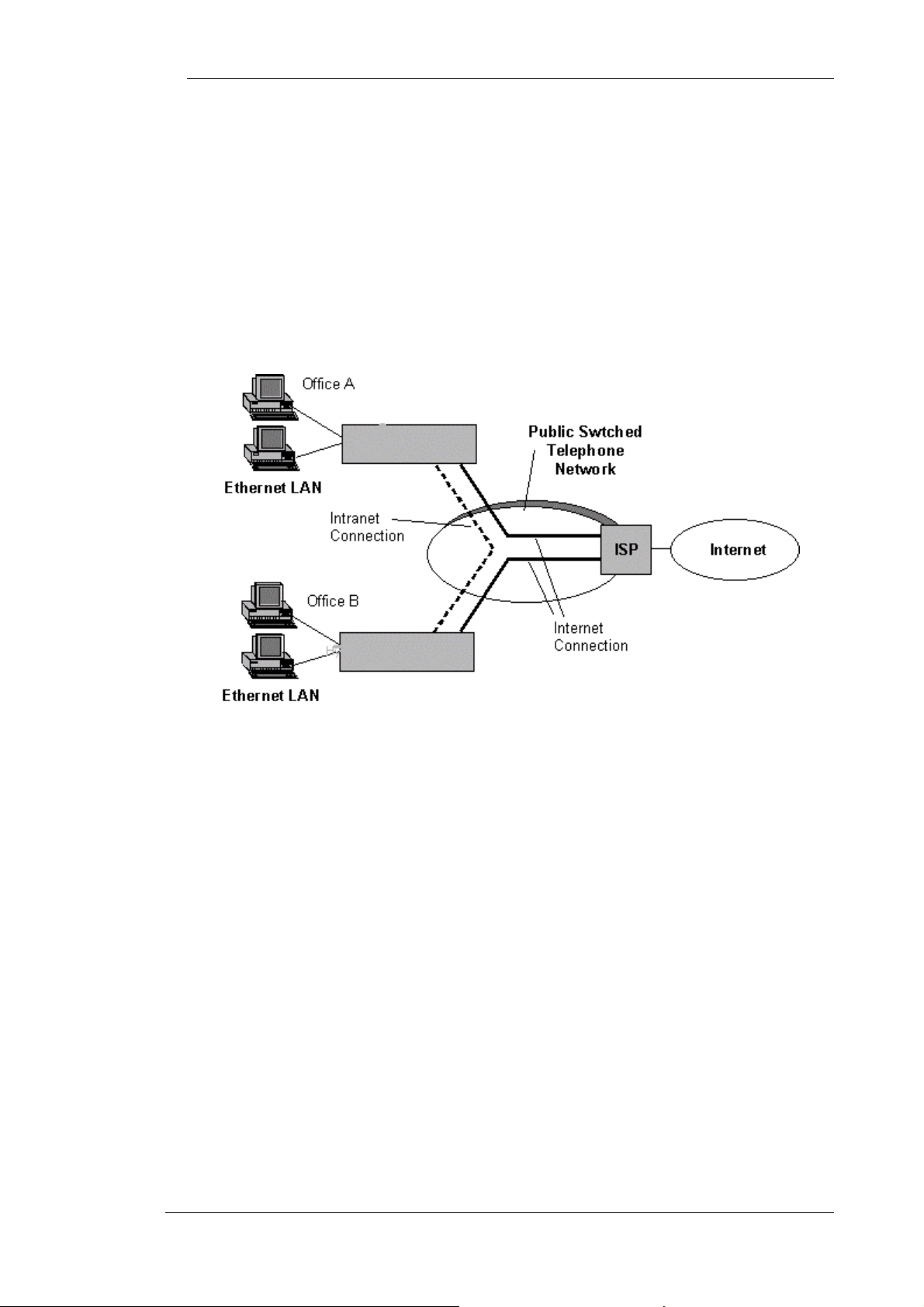
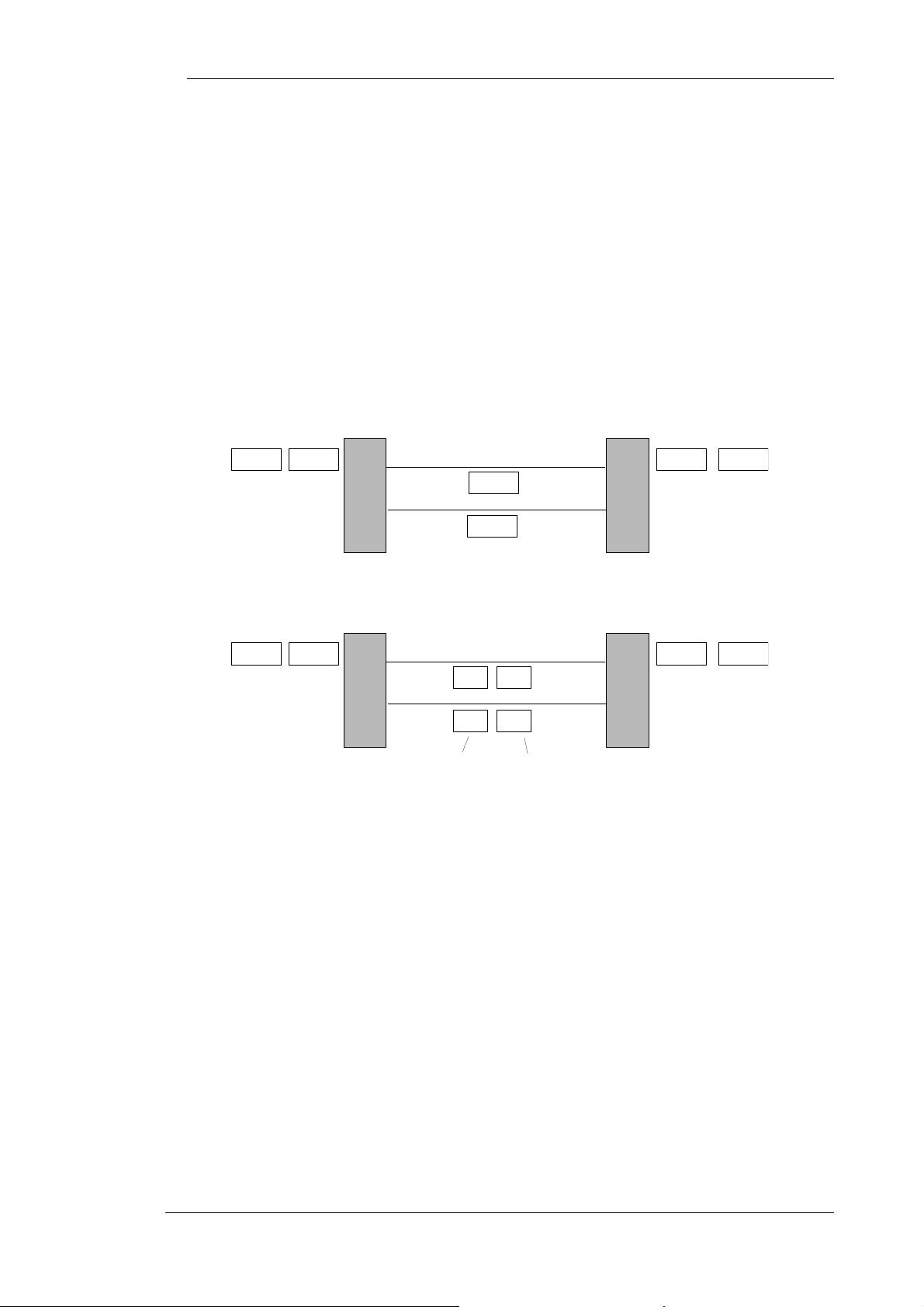
Internet and Intranet Connection Profiles
Hypertec ISDN 10T Router maintains two connection profiles one for Internet and the other for
Intranet. The Internet connection by definition is for users to reach Internet, the Intranet connection is
made between two offices. The Internet profile contains the configuration parameters required by the
Internet connection. The categories available under Internet profile are : ISDN, PPP, IP, and NAT. The
Intranet profile contains the configuration parameters required by the Intranet connection. The
categories available under the Intranet profile are ISDN, PPP, IP, IPX, and Bridge. NAT is intended
for Internet only where security and ISP monthly charge is of concerned. The IPX and Bridging
functions are intended for Intranet where protocols other than IP may be required. Users should make
sure not to configure conflicting information between these two profiles, such as setting the sa me
remote IP address or ISDN dialing number to both profiles. These two types of connections are shown
in Figure 0-1, Internet and Intranet Connections.
Figure 0-1, Internet and Intranet Connections
IP Address and Subnet Mask
The address used for IP routing is the IP address. An IP Address is a 32-bit address which must be
assigned to every host that wants to use IP to communicate across the Internet. If you are connecting to
the Internet, in general the IP addresses of the computers and router are assigned from your Internet
service provider unless Network Address Translation (NAT) is used which we will discuss later.
The IP address are specified in a.b.c.d where a,b,c,d are each decimal numbers between 0 and 255 with
some restrictions applied. The Hypertec Router Ethernet IP address must be on the same network as
your PCs on the LAN. A network can be subnetted into one or more physical networks which form a
subset of the main network. The Subnet Mask is a number identifying a subnet within a network.
Routing Table
In order to move data from port to port, the router has to make routing decision based on the routing
table. Each routing entry describes what network can be reached through which interface via a certain
gateway.
Some routing entries are system created based on the router interface configuration. Some routing
entries may be created by users & classified as static routes, and other may be created based on the
information learned from the router protocol (eg. RIP). Static Routes are a cost-saving feature which
avoids running RIP over WAN links. The active route is advertised by Hypertec Router via RIP (if
enabled) on its LAN interface. For the Hypertec ISDN router, the default route created by the system is
automatically set toward Internet remote router. Users need to enter static route entries only when there
are multiple subnets at the Intranet remote end.
IP Address, Un -Numbered, or Numbered
9
Page 17

Concepts and Principles of Operation
You can set Hypertec Router IP addresses to be 'un-numbered' or ‘numbered’. By setting it to “unnumbered”, you can route IP over a link between two devices without assigning IP addresses to the
ISDN interfaces. This allows you to save valuable IP address space. There are situations where a
traditional “numbered” IP address scheme is inevitable.
In Figure 0-2, Unnumbered ISDN Link, there is an unnumbered link between an ISDN router and a remote
router at the ISP site. These two devices can still communicate with each other, although neither of the
ISDN interfaces has been assigned an IP address. Instead, a route is assigned between a device and its
destination network, using interfaces instead of IP add r esses.
SOHO ISDN Router Remote Router at ISP
eth1
50.0.0.1
unnumbered link
eth1
90.0.0.1
Figure 0-2, Unnumbered ISDN Link
In Figure 0-3, Numbered ISDN Link, there is an numbered link between an ISDN router and a remote
router at the ISP site. An IP address is assigned at each end of the numbered link.
SOHO ISDN Router Remote Router at ISP
eth1
50.0.0.1
numbered link
66.0.0.1 66.0.0.2
eth1
90.0.0.1
Figure 0-3, Numbered ISDN Link
Dynamic IP address Assignment
If you are subscribing to a single user account, the ISP won’t assign you a static (semi-permanent) IP
address(es). Instead, an IP address is dynamically assigned at the login time. Hypertec ISDN 10T
Router will accept the dynamically assigned IP address for its ISDN interface and update the routing
table accordingly. The assigned IP address will be freed, and the associated routing table entry is
deleted when the session is closed. The NAT feature is required for multiple LAN users to access the
Internet using the single IP account.
10
Page 18

Concepts and Principles of Operation
IPX
IPX is the protocol used by Novel Netware as the network layer protocol. Novel IPX also uses
Routing Information Protocol (RIP) for routing protocol. The IPX address consists of two parts: a 4-
byte network number, and a 6- byte node number. Often, the node number is assigned as the Ethernet
MAC address. In a bridging environment, all Netware clients and servers share the same external
network number. In an IPX routing environment, networks connected by IPX routers are assigned with
unique IPX network numbers.
An IPX client wishing to connect to a Netware server first sends a “find nearest server” request trying
to locate a server. After the server's response to the request, the Netware client login process may
begin. If a Netware server is not locally connected to the client’s network, the router connecting to the
client’s network is responsible for responding to the “find nearest server” request. A router such as
Hypertec ISDN 10T Router learns of the existence of a remote server by manual configuration, and
through Servi ce Advertising Protocol (SAP).
Internal IPX net:
00-00-11-22
Internal IPX node:
00-00-00-00-00-01
server
client
Router
Router
IPX Address
external network AA-AA-AA-AA
Netware 3.x and later use the notations of external IPX address and internal IPX address. Any Netware
device physically connected to a network have an external IPX address. A Netware server such as a
file server is also assigned with an internal IPX address. The internal address refers to the internal
network within a server allowing internal processes to communicate. All external and internal
addresses must be unique from one another.
external network BB-BB-BB-BB
IPX Frame Type
The IPX frames can be encoded in 4 frame types of the following formats:
Ethernet II (0x81,0x37,...),
802.3 (length, 0xFF, 0xFF,....),
802.2 (length, 0xE0, 0xE0, 0x03, 0xFF, 0xFF,......), and
SNAP (length, 0xAA, 0xAA, 0x03, 0x00, 0x00, 0x00, 0x81, 0x37,...).
Among them, 802.3 and 802.2 are two most commonly used format. Hypertec ISDN 10T Router
routes only IPX traffic of certain frame type. Other frame type of IPX traffic may be bridged if so
enabled.
11
Page 19

Concepts and Principles of Operation
RIP
Novel IPX also uses Routing Information Protocol (RIP) as a routing protocol. Alt hough it is similarly
named to the IP equivalent, it uses a different protocol. IPX RIP broadcasts packets to the network
every 60 seconds to inform other IPX routers or servers about its network. Upon receiving an IPX RIP
packet, a router adds one to the hop count of each router advertised and broadcasts a RIP packet to
other networks it is connected to.
SAP
Netware Servers such as file servers use SAP protocols to advertise their service throughout the
network. A router such as Hypertec ISDN 10T Router listens to the SAP packets from servers to learn
what services are available in the local network. Routers also exchange SAP packets so that the router
can learn what services are available at the remote networks. With that global knowledge, the router is
able to respond the “find nearest server” request for the remote IPX networks.
IPX Spoofing
A Netware server regularly send a “keep alive” message to a logged -in client every 3-5 minutes for
connectivity verification. If a client fails to respond within the allowed limit, the server closes the
client’s connection. The IPX “keep alive” packets tend to keep the dial-up connection on line. To
minimize the un-necessary dial-up connection time, Hypertec ISDN 10T Router is equipped with an
IPX spoofing function which will return the “keep alive” on behalf of the remote Netware clients for a
pre-configured period. A dial-up call may be triggered by the “keep alive” packets only after the
spoofing timer expires.
PPP
The Point-to-Point Protocol (PPP) is the de-facto standard as the link encapsulation protocol for
Internet Access. PPP consists of a suite of protocols including LCP, PAP, CHAP, IPCP and other
related protocols. Link Control Protocol (LCP) is used to negotiate the link parameters, such as what
authentication protocol to use. LCP is specified in RFC 1570. Password Authentication Protocol
(PAP), and Challenge Authentication Protocol (CHAP) are used to inform the remote site (eg. ISP)
about which router is connecting to it. CHAP and PAP are specified in RFC 1334. IPCP is used to
negotiate IP specific parameters such IP address. IPCP is specified in RFC 1332.
PAP/CHAP
When a CHAP authentication connection to the ISP is attempted, the remote router or access server
sends a CHAP packet to HyperRoute. The CHAP packet "challenges" Hypertec Router to respond. The
challenge packet consists of an ID, a random number, and the host name of the remote router. The
required response consists of an encrypted version of the ID, a secret password, and the random
number of the local name. When the remote router or access server receives the response, it verifies the
secret password by performing the same encryption operation as indicated in the response and looking
up the required host/user name. Hypertec Router and the remote router must agree on the identical
secret passwords. By transmitting this response, the secret password is never transmitted in clear text,
preventing other devices from stealing it and gaining illegal access to the system. Without the proper
response, the remote will reject the PPP connection request.
If PAP authentication is enabled, when attempting to connect to the ISP or remote router, it is
necessary to send an authentication request including the user name and password. If the user name
and password are accepted, the ISP or the remote router sends an authentication acknowledgment to
conclude the authentication process.
There is a configuration choice of two sets of authentication protocol and password. One set for
Internet connection and one set for Intranet connections. Each set consists of two pairs of
authentication configuration. The Dial-out authentication password pair is ap p lied to the PPP
connection initiated by Hypertec ISDN 10T Router. The call-in authentication-password pair is app lied
to the PPP connection initiated from the remote end. The dial-out authentication protocol (none, PAP,
CHAP) specifies the authentication protocol that H ypertec ISDN 10T Router will insist on when
initiating a PPP connection. The remote end is supposed to accept the specified authentication protocol
for the PPP negotiation to proceed. The setting of “either” as the call-in authentication protocol allows
12
Page 20
Concepts and Principles of Operation
Hypertec ISDN 10T Router to negotiate for either PAP or CHAP authentication protocol whichever
the remote end prefers.
Multilink PPP
The PPP Multilink Protocol (RFC 1717) is a standards based extension of the PPP (Point-to-Point
Protocol) standard. It allows you to combine channels into a 'Multilink bundle' so that data can be sent
at higher rates. Multilink PPP can implement a feature known as 'packet fragmentation' where larger
individual packets are chopped into smaller fragments. These fragments are then distributed among
two channels in use. The receiver at the other end of the links collects the fragments, reassembles them
and delivers them in the original order.
Multilink PPP allows packet fragmentation over two B channels to reduce latency and speed up
transmission. The actual implementation of fragmentation howeve r demands significant CPU
overhead. This overhead prevents most ISDN SOHO router vendors from doing the packet
fragmentation, instead packets are distributed between two B channel in a round-robin fashion.
P1 P2 P2 P1
R1 R2
P1
P2
Figure 0-4, Packet transmission without fragmentation, round-robin
When packets are sent with fragmentation, the larger packets are chopped into two fragments of equal
size and distributed from Router 1 to Router 2 over the two channels in use.
P1 P2 P2 P1
F1
R1 R2
Packet 2 Packet 1
Figure 0-5, Packet transmission with fragmentation, chop-in-half
Not all ISDN routers or access servers accept packet fragmentation. To guarantee compatibility, the
Hypertec Router sends packets in round-robin over the Multilink PPP. Hypertec ISDN 10T Router can be
configured to accept both round-robin and fragmented packets. There is a possibility of packet out-ofsequence when sending and receiving packet in round-robin fashion, Hypertec ISDN 10T Router will reorder the packets when compression is enabled. This will minimize the history reset request caused by the
packet out-of-sequence. The diagram above illustrates how packet fragmentation changes the way packets
are transmitted between two routes. When packets are send in round-robin, packets are sent whole across
the B-channels.
F1
F2 F2
13
Page 21

Concepts and Principles of Operation
(
)
Dial on Demand
When the ISDN router receives packets from the Ethernet and decides to route packets to the WAN
interface, an ISDN call is automatically made to the remote end, followed by the PPP negotiation. The
PPP connection to the remote router is triggered automatically by the LAN traffic without user
intervention. On the other hand, when the traffic activity over the connection become idle for a certain
period, the ISDN router automatically releases the ISDN/PPP connection.
Bandwidth on Demand
If Multilink PPP is enabled, the router will bring up the second B channel when the traffic activity on
the first PPP channel passes beyond a certain threshold for a certain period, as specified in “1->2 util”
(increase from 1B to 2B), and “ave interval” (average) parameters. The router may also release the
second B channel when the data traffic activity on the second channel has fallen below a certain
threshold for a certain period, as specified in “2->1 util”(decrease from 2B to 1B), and “ave interval”.
Bandwidth
Kbits/sec
128
1
2
64
A
B
5
secs
01020
A = 80% volume of one B-Channel (64 Kbits/sec)
B = 30% volume of one B-Channel
3
30
Time (in seconds)
4
5
secs
40 50 60
5
Traffic bandwidth
Available bandwidth
128 Kbits/sec
Figure 0-6, Bandwidth on Demand
Bandwidth on Demand occ urs dynamically on an 'as needed' basis. Before you begin to set up
Bandwidth on Demand parameters, you need to d ecide at what point you want the second B -channel to
open. For example, you may want to open the second channel when the first is at 50% of its maximum
throughput . You also need to work out how long you want traffi c on the first B-channel to remain at
this percentage level before the second channel opens up. The diagram above illustrates how
Bandwidth on Demand works.
When an ISDN call is made, one B-channel is opened. Point 1 shows when data reaches the traffic load
percentage value. This means that the volume of data has reached the percentage value that you have
set on “1->2 util”. You can configure Hypertec Router to wait for a set length of time before bringing
the second B-channel into operation. In this case, data volume must exceed 80% volume for a certain
length of time, as in “ave interval” before the second B-channel is opened. Point 2 marks the point at
which data volume has exceeded the traffic load percentage value for five seconds. The second ISDN
B-channel now opens automatically, and remains open until data volume drops b elow a configurable
level as in parameter “2->1 util”. Data is shared equally between the two B-channels. At point 3 in the
14
Page 22

Concepts and Principles of Operation
diagram, traffic decreases temporarily before increasing again. Because bandwidth requirements can
change suddenly like this, the second B-channel waits for a period of time before closing down. In the
above diagram, this value has been set to 5 seconds. You can set this time to s uit your own
requirements.
At point 4, data drops below the lower traffic load percentage value. Because traffic volume must
remain below this threshold for a certain length of time, the second B-channel does not close until
point 5 (5 seconds later) has been reached.
Data Compression
Data compression allows the router to send and receive data more efficiently by compressing the data at
sending and de-compress the data at receiving. When compression is enabled, the Hypertec Router
negotiates using a STAC LZS compression sc heme using the Compression Control Protocol (CCP).
Hypertec ISDN 10T Router supports both Ascend’s pre-standard compression scheme, and the standard
compression scheme as specified by ITEF. Depending on the actual data pattern, the STAC compression
algorithm may accomplish the compression ratio of 4:1 against an ASCII file. No data compression can be
gained against a file which has already been compressed. When working with the Multilink PPP protocol,
the compression algorithm is inappropriate as the frequent packet out-of-sequence condition can cause
either end to request a compression history reset.
Calling Line Identification (CLID)
Calling Line Identification (CLI) or Caller ID is a mechanism for identifying incoming calls. You may be
able to order CLI from your telephone company as part of your ISDN Service. The Hypertec Router
allows one CLID for each Profile. In many circumstances, the incoming call indication signal does not
include the Calling Line Identification (directory number) of the device which has just called you, or the
Calling Line Identification (CLID) may not be passed to the Hypertec Router . You may want to disable
CLID authentication, instead, use the Challenge-Handshake Authentication Protocol (CHAP) for
additional security if these circumstances apply.
Callback
Callback is available on ISDN circuits. It allows a router to request a return call from a remote router,
meaning that when an incoming call is received on a circuit, the router drops that call and calls back
the originating router. This feature allows you to take advantage of any differences in call charges and
obtain centralized billing. Callback also provides additional security.
There are two scenarios of Callback operation:
1. Caller ID (CLID)
A call arrives at the Hypertec Router, which has been configured to accept Callback requests with
the CLID enabled. The HypertecRouter checks if the CLID matches its CLID configuration. If a
match is found, the Hypertec Router rejects the incoming SETUP message and calls back the
originator using the number presented by Caller ID. This method means that there is either no
charge or a minimal call setup charge (service provider dependent) to the originator. If the
originator is not configured to request Callback but the receiving circuit is configured to call back
the originator, then when a call arrives it will still be called back. If the originator is configured to
request Callback but the receiving end is not configured to call back, the receiving end will accept
the call and the originator will pay the cost of the call.
2. PPP
If CLID is disabled in configuration in the Hypertec Router, a call is accepted by the Listener
circuit then Callback is negotiated using PPP authentication. This method will mean a small cost is
incurred at the originating end since the call has to be accepted before Callback is negotiated. If the
PPP negotiation fails then the call is dropped as usual.
Packet Filtering, IP Access List
To provide an additional level of security once the connection is established, the Hypertec Router
allows users to configure access lists against the IP traffic. The access list specifies what kind of data
15
Page 23

Concepts and Principles of Operation
packets are to be filtered or forwarded. If no access list is specified, all valid packets will be forwarded.
You can specify in the IP access list the following criteria: source IP address, destination IP address,
source port number, destination port number, and the protocol which when matched will be forwarded
or filtered.
NAT
The ISP generally offers two type of accounts to SOHO users. The Single User account, and the LAN
Access (Multiple Users) account. The Single User account is often referred as Terminal Adapter or
Modem account where single user Internet access is assumed. The LAN Access account cost more
than the Single User account because multiple IP addresses are assigned. Network Tr anslation (NAT)
is designed to allow multiple users on the LAN to access Internet simultaneously using the Single User
account. In addition to cost saving, NAT is also useful in areas in which security or convenience are a
concern. It is convenient in the sense that, the users don’t have to change the private legacy IP
addressed already in use.
In order for the outside world to access the TCP/IP servers on the LAN, the Hypertec Router allows a
list of internal IP addresses to be associated with FTP, Telnet, HTTP, and Email servers. Traffic
destined for the list servers are forwarded to the specified IP addresses. The inbound traffic distribution
works only for static IP address arrangement where you can register an IP address against the domain
names. You will not have an IP address to register or publish when access to the Internet is via a
“single-user” account.
There are some limitation on the NAT application :
1. If the ISDN connection drops (e.g., because of an idle time-out), it is most likely that upon
reconnection you will get a different IP address assigned. For example, if you are using a web
browser and the connection drops because you go idle, if you then click on a link, you might get an
error message because you now have a different IP address.
2. Certain applications, like some UDP-based Internet games and chat client programs, will work
unreliably or not at all when using NAT because they report their private IP address to the server
instead of the "correct" dynamically assigned address. The remote application while sending UDP
packets toward the private IP address will not be able to deliver.
3.
NAT is available for Internet connections only. The Intranet connection is not affected by the
Internet NAT setting.
16
Page 24

Concepts and Principles of Operation
DHCP
Managing IP addresses in an organization is often a headache for the MIS staffs. To ease the IP
address management, the Dynamic Host Configura tion Protocol (DHCP) i s invented by IETF. DHCP
protocol works in a client server configuration. One or more DHCP servers may be installed in the
network. A workstation running DHCP client software (eg. Windows 95), whe n configured t o request
IP addresses from the network, will send a DHCP request to the network asking for IP add r ess
assignment. In addition to assigning the IP address, the DHCP server can also provide other TCP/IP
configuration data such as IP sub-net mask, default gateway IP address, DNS server IP address(s).
Hypertec ISDN 10T Router with DHCP enabled, can function as a DHCP server.
Voice Communication Service
Voice Preemption
If you pick up a phone while a 2-channel data call (Multilink PPP bundle) is active, the Hypertec
Router drops one of its data links to service the voice call unless the preemption is configured as
disabled. An AT&T 5ESS switch limitation prevents users o f AT&T Customer Multi-point or Point-to-
Point service from receiving voice calls, when both data channels are in use. Outgoing calls are not
affected by this switch limitation, because they are controlled locally at the Hypertec Router . If you
are using AT&T Multi-point or Point-to-Point service, and you want to make sure that voice calls are
received, you should configure the link encapsulation protocol to PPP for both Internet and Intranet
profile. However, this limits the Hypertec Router to 1-channel data calls, so each data call can handle a
maximum of 64 kbps. The voice call will not be accepted if there is two 1-channel data calls in active.
Basic Rate ISDN Provisioning for United States and Canada
Introduction
This document outlines the steps required to successfully order the correct BRI ISDN service from your
service provider for the Hyperte Router .
Line Provisioning Service
Line provisioning service can supply the ISDN provisioning information you require. T his information
is available at the following number (US and Canada only):
1-408-867-2045
Ordering the ISDN Line
You can order many different variants of ISDN. To ensure that you get the correct variant for the
Hypertec Router, you need to give your service provider certain information. In return, they will tell
you the correct parameters to use when configuring the Hypertec Router .
17
Page 25

Concepts and Principles of Operation
You must tell your service provider how you need the line configured for data, voice and other
optional services.
Your service provider needs to tell you:
• the ISDN service and switch type
• the ISDN directory (or phone) numbers
• associated Service Profile Identifiers (SPIDs) (if required).
ISDN Switches and Services Supported
The Hypertec Router supports the most common switch types used in Northern America:
• AT&T 5ESS
• Northern Telecom DMS-100
The Hypertec Router is also compatible with the National ISDN service offered through ,AT&T, Northern
Telecom switches.
There are different ISDN services available on these switches. The Hypertec Router supports the
following services:
Switch type ISDN Service
AT&T 5ESS Custom Point-to-Point
AT&T 5ESS Custom Point-to-Multipoint
NT DMS-100 Custome Point-to-Multipoint
AT&T 5ESS National ISDN 1 (NI-1)
AT&T 5ESS National ISDN 2 (NI-2)
NT DMS-100 National ISDN 1 (NI-1)
NT DMS-100 National ISDN 2 (NI-2)
18
Page 26

Concepts and Principles of Operation
Provisioning the ISD N Line
To make sure that you get the correct ISDN service for the Hyperte Router, you must tell your service
provider how you need the ISDN line provisioned. This means whether you want data, voice or a
combination of the two, what extra services you need and, possibly what terminal type you require.
Different service providers require this information in different ways; increasingly they are using ISDN
Order Codes for simplicity, but some still require specific s witch type details.
Using ISDN Order Codes
Placing an order for ISDN has been greatly simplified recently for National ISDN (NI-1 and NI-2)
services by the use of ISDN Order Codes (IOC). This allows you to order a specific service by simply
quoting an order code rather than having to use a lot of complex subscription parameters.
There are three ways of ordering ISDN using these ISDN Order Codes:
• Capability Packages
Note: The Hypertec Router complies with Capability S.
• Solution Sets
• EZ-ISDN
Note: The Hypertec Router complies with and is registered against EZ ISDN-1.
There are a number of other IOCs that can be used when ordering ISDN for the Hypertec Router .
They may not all be available in your area and you may need to check this with your service provider.
Capability Packages
The following list shows the Capability Packages that are appropriate for the Hypertec Router .
Note: The Order Code used will depend on the data and voice services required; the Hypertec Router
will not necessarily exploit all the features of a given service.
Capability
Package
B Only provides data on one B channel. Includes CLI (Calling Line
C Provides alternate voice/data on one B channel. Includes CLI.
G Includes voice on one B channel and data on the other B channel.
I Includes data on two B channels. No voice capability provided.
J Includes alternate voice/data on one B channel and data on the
K This is the same as J but also includes ACO for the voice.
M* Includes alternate voice/data on two B channels. Includes CLI.
R Almost the same as I except that two directory numbers are
S* Almost the same as M but always with two directory numbers.
U* Includes alternate voice/data on two B channels. Includes CLI and
V* Includes alternate voice/data on two B channels. Includes CLI and
ISDN Service
Identification or Caller ID).
Includes CLI and Additional Call Offering (ACO).
other B channel. CLI is included.
assigned. With package I, one or two directory numbers may be
assigned depending on the central site switch.
Includes CLI. (This service complies with and is registered against
EZ-ISDN 1.)
ACO.
ACO.
Those Capability Packages marked with a * are the recommended codes to use, if available. You will
get the most functionality from your Hypertec Router through these services.
19
Page 27

Concepts and Principles of Operation
Solution Sets
Solution Sets have been created to correspond to a particular customer application. The Solution Sets
appropriate to the Hypertec Router are:
Solution Set ISDN Service
Work at Home 3a
Work at Home 4a
Desktop Collaboration 2a
Provides voice on one B channel and data on the
other B channel. Includes ACO and CLI (Caller
ID).
Provides voice/data on one B channel and data
on the other B channel. ACO and CLI are
included.
Includes voice/data on one B channel and data
on the other B channel. ACO and CLI are
included
EZ-ISDN
EZ-ISDN codes mirror some of the Capability Packages described previously. They are another
method of ordering the correct ISDN service.
In addition, to simplify the process of provisioning an ISDN line, the Hypertec Router complies with
and is registered against EZ ISDN-1. You should ask your ISDN service provider for EZ ISDN-1
provisioning. The Hypertec Router conforms to Bellcore requirements for connection to National
ISDN-1 services. If EZ-ISDN is not selectable, the Hypertec Router also works fine with Intel-Blue
provisioning.
20
Page 28

Concepts and Principles of Operation
Using Specific Switch Parameters
Your service provider may require specific details about the parameters for the switch you are
connected to. The parameters will depend on the service you are selecting. The following information
provides the switch settings that are appropriate for the Hypertec Router connectivity.
AT&T 5ESS Custom
Switch Feature Value
Term Type A
Call Appearances 1
CSV 1 per Directory Number
CSV Limit 2
CSD 1 per Directory Number
CSD Limit 2
National ISDN 1 & National ISDN 2
For National ISDN 1, you receive two Directory numbers and, as a result, some of the switch features
are per Directory Number.
For National ISDN 2 you get one Directory Number.
Switch Feature Value
Term Type A
CSV 1
CSV Limit 2
CSD 2
CSD Limit 2
CSV Notification Busy Limit 1
CSD Notification Busy Limit 1
EKTS No
ACO Yes
Supplementary Services
There are some common supplementary data services that are applicable to the Hypertec Router,
namely:
• Calling Line Identification or Caller ID
• Multiple Subscriber Numbering (MSN)
Calling Line Identification (CLI) or Caller ID
CLI provides the caller’s telephone number when you receive a call. This information is provided by
the network and not the caller and so can be used as a security measure to identify calls to be accepted
and rejected.
You should order CLI if available.
Multiple Subscriber Numbering (MSN)
MSN allows multiple telephone numbers to be assigned to a single BRI connection. This allows you to
assign specific numbers to specific devices.
For the Hypertec Router, there will be one LAN connected and one or two analog devices (e.g.
telephone, fax). It is possible to give each device a separate number through multiple subscriber
numbering, allowing calls to be routed to the correct analog device. This will also depend on the
service you are connected to.
21
Page 29

Concepts and Principles of Operation
When connecting to AT&T 5ESS Custom, you are provided with one telephone number (directory
number). If you only need to connect one analog device (say a telephone) then one number is all that is
required, but if you have two analog devices then you will need to subscribe to MSN. This will allow
you to differentiate between the two analog devices and direct calls to the correct device.
When connecting to National ISDN 1, you are provided with two telephone numbers (directory
numbers). The Hypertec Router can differentiate between voice and data calls. This means one
telephone number can be assigned to, say, the telephone (and the call will be directed to the correct
device automatically) and the other directory number assigned to, say, the fax machine. There is no
requirement for extra MSN service in this case.
Terminal Types
When connecting to an AT&T switch, you may need to specify a terminal type to the service provider
as part of the ISDN provisioning. This is a letter that defines the type of device you are connecting to.
For the Hypertec Router the correct Terminal Type is A.
Information from your Service Provider - Directory numbers and SPIDs
In return for providing the ordering information, your service provider will provide you with Directory
Number(s) and SPID(s). SPIDs are not provided for the AT&T Custom service.
A Directory Number is simply the address or ISDN telephone number for the ISDN line assigned by
the service provider. Each ISDN line receives (at least) one telephone number, called the Primary
Directory Number. Depending on the service offered by your service provider, you may also have a
second directory number.
Your service provider will provide you with the Service Profile Identifiers (SPIDs). These are
associated with the service you have ordered and you must use these as part of the configuration for
Hypertec Router before any ISDN connections can be made (except for AT&T Custom).
The SPID is similar to the ISDN telephone number and its format is unimportant so long as the
information is entered correctly when configuring Hypertec Router .
If you subscribe to NI-1 you will get two directory numbers and two SPIDs. If you subscribe to NI-2
you will get one directory number and one SPID.
More Information
You can get more information on ISDN provisioning from the following Web sites:
• http://www.bellcore.com/ISDN/index.html (Bellcore’s ISDN home page)
• http://alumni.caltech.edu/~dank/isdn (Dan Kegel’s home page)
For more information on ISDN (including ISDN provisioning), consult the following book:
• ISDN for Dummies by David Angell, published by IDG Books. ISBN 1-56884-331-3.
Configuration and Management
Introduction
The Hypertec ISDN Router can be managed via three means :
1. NMS Windows Program
2. Web Browser
3. ASCII Console
NMS is a Windows application program running on Windows 3.1, Windows 95, and Windows NT
platforms. Among the above management tools, NMS delivers the richest set of functionality in
managing the Hypertec ISDN 10T Router . NMS consists of two applications : the SNMP
management, and the SNMP monitor (C l earMon). The SNMP manage ment is used to configure the
ISDN router, and SNMP monitor is used to monitor the LAN, ISDN channel activities, and events.
Most PCs nowadays have a web browser installed. Their popularity makes the Hypertec ISDN Router
manageable from virtually any PC workstation. When managed by a web b rowser, the HTTP requests
22
Page 30

a
from a web browser are delivered to a software module called EasyWeb, which translates the HTTP
requests into SNMP requests and forwards them to the Hypertec ISDN 10T Router. The ISDN router
returns the SNMP responses to the EasyWeb which in turn translates them back into HTTP responses
and forwards them back to the browser.
The console offers the most fundamental user interface for router management. The Hypertec Router
displays the ASCII based menu on a terminal, or on a PC running a terminal emulation program. The
console management focuses on the most basic management information such as “Quick Conf” for
Internet access, and Ethernet/ISDN statistical data.
Because it is the most feature rich and the easiest to use, the NMS alternative is clearly the
recommended choice for configuring and managing the Hypertec ISDN 10T Router. For this reason,
this chapter is mostly devoted to this alternative. Descriptions of the other two alternatives are
however, also included.
NMS
Configur
General
Once logged in, the main menu shows up with a title bar “ISDN Router NMS Manager” at the top,
system utilities (File, Diagnostic, Product info, View, Help) below it, and rest is the main body of the
main menu. The main body is organised into two levels. The top level menu contains si x items: Quick
Config, Local, Internet, Intranet, SNMP, and Statistics. Each top level menu contains one or more
bottom level items. The rest of the main body shows the contents of the active sub-menu which is
determined by the top level menu item, and the bottom level menu item.
NMS Menu Structure
23
Page 31

a
The NMS menus are organized into a hierarchical structure shown in Figure 0-1, NMS Menu
Structure:
Configur
24
Page 32

a
Login
Configur
Quick Config
Internet
Local Internet
ISDN
ISDN
IP
DHCP
PPP PPP
IP IP
NAT IPX
Intranet
ISDN
Bridge
SNMP Statistics
ISDNSNMPEthernet
Ethernet
Trace
Figure 0-1, NMS Menu Structure
The “Quick Config” menu provides a quick and easy way for users to configure the ISDN router for
Internet Access. For straightforward Internet access, this menu is probably the only menu that is
required. For more advanced configuration, the “Local”, “Internet”, and “Intranet” menu can be handy.
The “Local” menu is for configuration of the router itself. The “Internet” menu is for configuring
specifics of the Internet connection, and the “Intranet” menu is for configuring specifics of the Intranet
connection. The “SNMP” is used to set a basic MIB II system, MIB parameters and destination to
where the traps will be delivered when enabled. The “Statistics” menu provides a very useful tool for
monitoring the router operation and for trouble shooting.
In addition to the menus described above, there are a number of system utilities providing services
such as up/down loading of router configuration files, updating router firmware, resetting the device,
disconnecting Internet/Intranet, and help information.
NMS Windows
NMS displays use the Windows 3.1, Windows95/NT conventions for windows management such as
positioning, sizing, and closing windows.
A tab for each top menu is displayed across the top of all windows. Clicking one of these tabs displays
the window for that top-menu. In each top menu window, tabs for each of the top menu’s sub-menus
are displayed. Clicking a sub-menu tab, displays the window for that sub-menu.
Each sub-menu windows displays the parameters that can be selected or entered in the form of fields
displayed within the window.
25
Page 33

Configur
a
Figure 0-2, Example Sub-Menu window
Figure 0-2 shows the window for the Internet sub-menu under the Quick Config main windo w. T his is
indicated by the bold lettering of the Quick Config main menu tab and the Internet sub-menu tab.
Clicking in a field selects the field for entering a value. The selected field is indicated by a blinking
insertion point (vertical bar). The Tab key can be used to tab to the next field and the Shift-Tab keys
can be used to tab to the previous field.
When entering a value, the normal word processing functions of delete, backspace, etc. apply. Pressing
the Enter key signifies that the entry is complete. In many instances, entering an invalid entry (for
example, an invalid IP address) will cause the entry to be rejected with an error message.
Some fields require the selection of an item from a menu. These fields are indicated by a down
pointing triangle to the right of the field. In the example, the Encap Protocol is such a field. Clicking
on these fields causes a drop down menu to appear. The user must select an item from the menu by
clicking it with the mou s e.
Some fields are indicated by small round buttons (called radio buttons). In these fields, the user makes
a selection by clicking on a radio button. In the example, Data Service has two radio buttons, namely,
56K and 64K. Only one radio button can be selected at a time.
Each screen includes a Refresh button and an Update button. The Refresh button is used to restore all
the values in the fields to those when the window was opened. The Update button is used when the
displayed field values are correct and the values are to be stored in the Hypertec Router.
26
Page 34

a
NMS System Menus
In addition to the NMS menus, which are indicated by the tabs along the top of the displays, there are
five System Menus which are listed along the very top of the window. These menus are File,
Diagnostic, Product Info., View and Help.
The File menu consists of:
Save Config
Load Config
Download Config to Device
Reset Config
Load Code
Recent Files
Exit.
The “Save Config” is used to save the router configuration to a file, which may be restored at a later
time. The “Load Config” is used to restore the saved configuration file to the NMS and o ptionally to
the router. If you choose not to restore the configuration directly to the router, you can do it with
“Download Configuration to Device”. The “Reset Config” is used to reset the router configuration to
its manufacturer default values. Finally in this category, the “Load Code” is used to perform the TFTP
firmware update. Please use “Reset Config” and “Load Code” with care. The NMS will pop you a
warning dialog box for confirmation.
Configur
The Diagnostic menu consists of:
Ping
Reset Device
Disconnect Internet
Disconnect Intranet
The “Ping” utility is use to send ICMP messages to a destination station for connectivity check. The
“Reset Device” is used to reset the ISDN router. The “Disconnect Internet” is used to manually
terminate the Internet connection. And the “Disconnect Intranet” is used to manually terminate the
Intranet connection.
The Product Info. menu displays a window showing the version and release of the NMS product.
The View menu includes items for turning the Toolbar and Statusbar on and off.
The Help menu includes:
Index for accessing specific help topics
Using Help for information about the help system
About NMS for version and release information about NMS.
27
Page 35

a
NMS Toolbar
NMS also includes a toolbar of four items which are displayed as four icons at the top right of the
display.
Figure 0-2, NMS Toolbar
From left to right, these tools are:
• Open a file
• Save as
• About NMS
• Context sensitive help. Clicking this tool causes the mouse arrow to appear as a question mark.
The user can position the question mark over a field and click the mouse to get help information
about that field.
Required Information
Before configuring the Hypertec Router, certain information must be available. Some of this information
will be provided by the telephone company supplying the ISDN line (the ISDN provider), some will be
provided by the Internet Service Provider (ISP) and some by the local system administrator. The following
table shows the information that must be available.
Configur
Description Source Required or
Optional
Local Router Name ISP/MIS Required
Local IP Address ISP/MIS Required
Remote Router Name ISP/MIS Optional
Remote IP Address ISP/MIS Optional
Local IP Mask ISP/MIS Required
Remote IP Mask ISP /MIS Optional
Remote ISDN Number ISP Required
ISDN Switch Type Telephone Company Required
Phone Number 1 Telephone Company switch dependent
Phone Number 2 Telephone Company switch dependent
SPID 1 Telephone Company switch dependent
SPID 2 Telephone Company switch dependent
Dial-out Password ISP/MIS Required
Call-in Password ISP/MIS Optional
28
Page 36

a
Starting NMS
In Windows 95/NT, NMS is started by clicking Start/Programs/Wishco m NMS.
In Windows 3.1, NMS is started by clicking the NMS icon in the NMS window.
Logging Into NMS
The Login box pops up when you start the NMS program. The login dialog box serves two purposes:
It lets you enter the IP address to select a specific Hypertec ISDN 10T Router to manage, it also lets
you assign the IP address to an Hypertec ISDN 10T Router by clicking the associated check box.
This convenient way of assigning an IP address to the router does not require you to enter the IP
address through the console. If you assign an IP address to the Hypertec ISDN 10T Router through the
login dialog box, the Hypertec Router will reset itself after receiving the IP address assignment
request. The assigned IP address will be stored in the non-volatile RAM. The login dialog box will
wait about 10 seconds giving the router ample time to reset itself before polling the configuration data
from Hypertec Router and show you the main menu shown in next page.
There should be only one active Hypertec Router on the Ethernet when performing the IP address
assignment through the Login dialog box. If there is more than one Hypertec Router on the LAN,
power-down or detach from the LAN temporarily all the Hypertec Routers except the one that is
having its IP address assigned. Restore the other Hypertec Routers when the IP address has been
assigned.
Configur
Once you have successfully assigned the IP address to the router, you should not click the “assign IP
address” check box again next time you run the NMS program unless you want to change the router’s
IP address.
Figure 0-3 Login Dialog Box
29
Page 37

a
Quick Configuration Menu
The Quick Config (see Figure 0-4, Quick Config Menu) is the first menu you will see after co mpleting
the login dialog box.
There is only one sub-menu, Internet, for Quick Configuration menu.
If you have successfully logged into the router, you should see most fields in this page containing data;
if this is not the case, it indicates communication problems between NMS and the Hypertec Router.
See diagnostics hints in Chapter 5 if you run into such a problem.
For most users, the “Quick Config” menu is the only menu required to be entered for normal Internet
Access. The other menus such as “Local”, and “Statistics” are useful for diagnostics and advanced
manageme nt purposes.
Local Router Name
The local router name is the name assigned to this ISDN router. Any text character is acceptable up to 32
characters. The local router name is required by the ISP whenever you dial into your ISP’s point of
presence as part of the authentication procedure. It may be assigned to you by your ISP. Upper case or
lower case characters are significant for this field.
ISP Router Name
Configur
The remote router name is the name assigned to the remote router located at your ISP site. Any text
character is acceptable for up to 20 characters. The remote router name is used during the call-in
authentication process, and is not required when you want to dial into your ISP’s point of presence. In
general, your ISP assigns to you a remote router name for administration and reference purpose.
Figure 0-4, Quick Config Menu
30
Page 38

a
Local IP Address
The local IP address is the IP address assigned to this router. The IP address is entered in the standard
IP address format of a.b.c.d. The local IP address is required during the PPP negotiation. Please ask
your ISP if you don’t posse ss one, unless you have a conne ction with dynamic IP address allocation.
You would need to reset the router if this field gets changed.
Local IP Mask
The local IP mask is used to describe the local IP sub-netting. The IP mask is entered by clicking the IP
address bit map. The number of bits assigned for the IP subnet is shown next to the IP address bit map as a
decimal number for your reference. You would need to reset the router if this field get changed.
Dial (ISDN) number
The remote ISDN number is the ISP’s ISDN number you want to dial to gain access to the Internet. Your
ISP will provide you a list of ISDN numbers for you to choose from. In North America, the dialing of a ‘1’
followed by 10 digits is required in order to access the clean 64K BPS ISDN B channel(s). There should
be only digits in this field, no space or other termi nators are acceptable.
Encapsulation Protocol
Configur
The encapsulation protocol specifies the protocol you want to run over the data channel. Select PPP, if you
want to run single channel PPP. Select MLPPP, if you want two channel PPP.
Compression
The compression field specifies if the Stac compression protocol will be turned on for the Internet
connection.
Network Address Translation Enable
This field enables or disables the NAT function. This configuration becomes effective immediately after
setting.
Dial-out Authentication
The dial-out authentication field specifies which protocol you want to run as the PPP/MLPPP
authentication protocol when you initiate an ISDN call to your ISP. Most ISPs support PAP and CHAP
protocols.
Dial-out Password
The dial-out password specifies the password to use during the dial-out authentication process. This field
is case sensitive, and is given to you b y your ISP.
31
Page 39

a
ISDN Switch Type
The ISDN switch type specifies the type of ISDN switch to which your ISDN line is connected. The pull
down the "switch-type" menu, and select the one right for your ISDN line. The ISDN switch type has to be
correctly selected in order for your ISDN router to synchronize with the telephone company’s ISDN
switch. Please check your local phone company for the exact switch type. In Northern America, the
dominant switch type is National ISDN-1 (NI-1). For the rest of the world, the dominant switch type is
EuroISDN (ETSI). You would need to reset the router if this field get changed.
Phone Number 1
In Northern America, the local phone company assigns two phone numbers for each ISDN line. This
field specifies the first assigned phone number. This field is ignored outside Northern America. You
would need to reset the router if this field get changed.
Phone Number 2
In Northern America, the local phone company assigns two phone numbers for each ISDN line. This
field specifies the second assigned phone number. This field is ignored outside Northern America. You
would need to reset the router if this field get changed.
Configur
SPID 1
In Northern America, the local phone company assigns two SPIDs for each ISDN line. This field
specifies the first assigned SPID. This field is ignored for users outside Northern America.
The SPIDs, when given, come in different form usually in the format of prefix + phone number +
suffix. Please ask your local company for the exact assignment. You would need to reset the router if
this field get changed.
SPID 2
In Northern America, the local phone company assigns two SPIDs for each ISDN line. This field
specifies the second assigned SPID. This field is ignored for users outside Northern America.
The SPIDs when given come in different form usually in the format of prefix + phone number + suffix.
Please ask your local company for the exact assignment.
You would nee d to reset the r outer if you c hange this fi eld.
32
Page 40
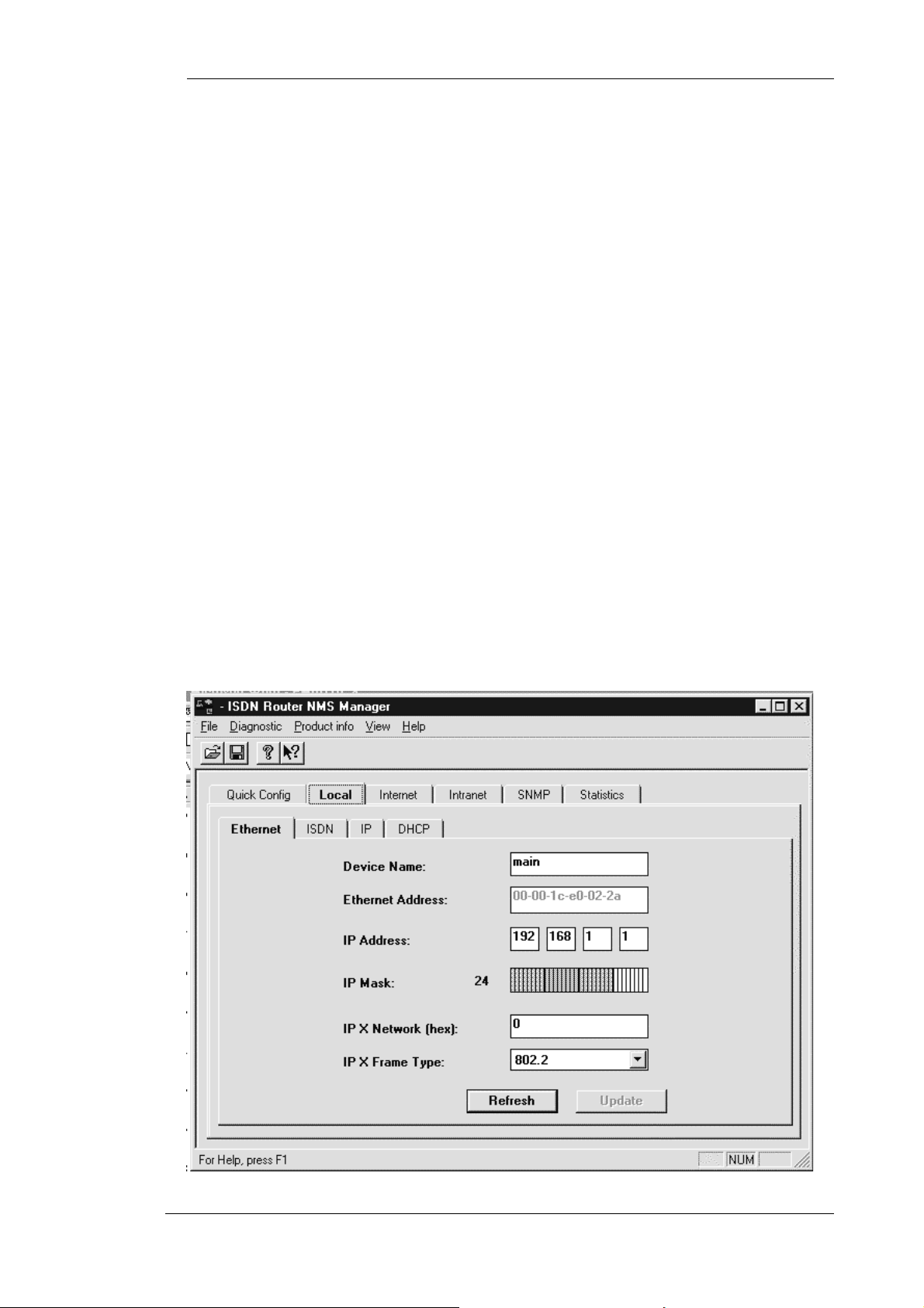
a
Dial-out Authentication
The dial-out authentication field specifies which protocol you want to run as the PPP/MLPPP
authentication protocol when you initiate an ISDN call to your ISP. Most ISPs support PAP and CHAP
protocols.
Dial-out Password
The dial-out password specifies the password to use during the dial-out authentication process. This field
is case sensitive, and is given to you b y your ISP.
Call-in Authentication
The call-in authentication field specifies which protocol you want to run as the PPP/MLPPP authentication
protocol when the ISP initiates an ISDN call to you. In normal operation, your ISP will not initiate a call
to you.
Call-in Password
The call-in password specifies the password to use during the call-in authentication process. This field is
case sensitive.
Configur
Local Menu
The local configuration contains the detailed local configuration information of this
router. Under the local configuration, there are three sub-menus : Ethernet, ISDN, IP,
and DHCP (server).
Local Ethernet Sub-menu
This Ethernet menu describes the Ethernet aspects of the local configuration. Some of the fields are linked
to the menu “Quic k Co nf ig”.
33
Page 41

a
Figure 0-5, Local Ethernet Window
Device Name
The device name specifies the name of this ISDN router. This field is linked to Local Router Name in the
menu “Quick Configuration”. Any text character is acceptable for up to 32 characters.
IP Address
The IP address describes the IP address assigned to this router by your ISP. This field is linked to Local
IP Address in menu “Quick Configuration”.
IP Mask
The IP mask describes the local IP sub-netting. This field is linked to Local IP Mask in menu “Quick
Configuration”.
IPX Network
The IPX network specifies the IPX network number of the Ethernet this router is directly connected to.
This 4-byte field is entered in 8 hex characters. With the given IPX network number, the Hypertec Router
creates a route entry in the IPX route table automatically. The IPX network has to be configured correctly
for the Hypertec Router to route IPX traffic.
Configur
IPX Frame Type
The IPX frame type specifies the frame encapsulation scheme this router will recognize as the IPX frames
from the local Ethernet. The IPX frame type is selected from the pull-down menu including Ethernet II,
802.3, 802.2, and SNAP. The Hypertec Router will route IPX packets of the specified IPX frame type.
Other frame type of IPX may be bridged if enabled.
Local ISDN Sub-menu
This Local ISDN menu (see Figure 0-6, Local ISDN Window) describes the ISDN aspects of the local
configuration. Certain parameters have to be set correctl y as given by your local telephone company for
the ISDN router to function properly. The switch type is a parameter that has to be entered precisely. For
North-America, the SPIDs are also required. Some of the fields are linked to the menu “Quick Config”.
Switch Type
The switch type specifies the switch type of the ISDN switch to which your ISDN line is con nected. The
switch type is selected by pulling down the switch-type box, and pick the one right for your ISDN line.
This selection has to be perfectly matched for your ISDN to function. Please check your local phone
company for the exact switch type. In Northern America, the dominant switch type is National ISDN-1
(NI-1). For the rest of the world, the dominant switch type is EuroISDN (ETSI) or NET3. For Germany
and France, the same EuroISDN switch type is supported.
B Channel Alarm Threshold
This field is used to set the alarm threshold. When the B channel usage level passes beyond this threshold,
the alarm LED will be flashed at high speed to catch your attention. Since there are two B channels in an
ISDN line, threshold set to 50% means either one of the B channel is in use 100% of the time, or both
channels are in use 50% of the time, or other equilibrium combinations of usage.
34
Page 42

Configur
a
Figure 0-6, Local ISDN Window
SPID 1
In Northern America, the local phone company assigns two SPIDs for each ISDN line. This field should
be ignored for users outside Northern America. Please refer to explanation under “Quick Config”.
SPID 2
In Northern America, the local phone company assigns two SPIDs for each ISDN line. This field should
be ignored for users outside Northern America. Please refer to explanation under “Quick Config”.
Phone Number 1
In Northern America, the local phone company assigns two phone numbers for each ISDN line. This field
specifies the first phone number. This field is ignored by users outside Northern America. Please refer to
explanation under “Quick Config”.
Phone Number 2
In Northern America, the local phone company assigns two phone numbers for each ISDN line. This field
specifies the first phone number. This field is ignored by users outside Northern America. Please refer to
explanation under “Quick Config”.
35
Page 43

a
Phone 1 Usage
The phone 1 usage specifies the which SPID the phone 1 is associated with. This field is ignored by users
outside Northern America.
Phone 2 Usage
The phone 2 usage specifies which SPID the phone 1 is associated with. This field is ignored by users
outside Northern America.
Data Usage
The data usage specifies which SPID(s) the data connection will be associated. This field is ignored by
users outside Northern America.
Local IP Sub-menu
The Local IP menu (see figure 0-8, Local IP Window) describes the IP protocol related parameters at the
local end of the ISDN router.
Configur
Route Table
For simple Internet Access where you want to connect an IP network to the Internet, the route table is
created automatically. You need to manipulate the IP route table only if you have more complicated
network topology. If your local Ethernet network is divided into multiple IP subnets, you need to add a
static route entry with interface (IF) marked as “ether” for each local subnet. If you plan to connect to a
remote office through the Intranet, and there are multiple IP subnets at remote site, you need to add a static
route entry with interface (IF) masked as “intra” for each remote IP subnets. You may choose to turn on
the RIP protocol to update the route table automatically instead of manipulating the route table.
Turning on the RIP protocol is not recommended. The periodical exchange of RIP protocol
packets will keep your ISDN line up all of the ti me, and results in an expensive ISDN bill.
36
Page 44

a
Route Table
Configur
Figure 0-7, Local IP Window
Access List
The access list is a filtering table for security application. You may selectively filter or forward certain
packet according to its source IP address, protocol, destination IP protocol, and destination port number.
For example, i f you intend t o block a web page being ret rieved from a certain web se rver, you ma y create
an entry for that particular IP address in the access list table to deny its traffic.
ARP Proxy
The ARP Proxy when enabled causes the ISDN router to send ARP responses to the LAN on behalf of
those remote IP addresses. ARP proxy enables the LAN users to communicate with the remote dial-up
users without configuring a static IP address for them.
RIP Protocol
The RIP protocol when enabled will cause the ISDN router to exchange RIP information with other RIPenabled routers in the system. Enabling the RIP protocol will create the complete IP route table. The IP
RIP packets are exchanged only when connection is up. IP RIP will not trigger ISDN connection.
37
Page 45

Configur
a
Local DHCP Sub-menu
The DHCP sub-menu contains the DHCP parameters which describe how the Hypertec Router as a
DHCP server operates, and what TCP/IP configuration information to release.
IP Address Pool (Start Address, En d Address)
The IP address pool as indicated by t he Start Address and End Address is used by the
DHCP server to release the IP addresses to the DHCP clients. The Hypertec Router
supports 16 IP addresses even if user specifies a IP address pool larger than 16 IP
addresses. The start address and end address are set by default having the same IP subnet
as the router’s Ethernet address.
Subnet Mask
While leasing an IP address to a client, the IP Subnet Mask is among other configuration information
available from DHCP server.
Gateway Address
While leasing an IP address to a client, the gateway IP address is among other configuration
information available from DHCP server.
Primary DNS
While leasing an IP address to a client, the primary DNS IP address is among other configuration
information available from DHCP server.
Secondary DNS
While leasing an IP address to a client, the secondary DNS IP address configuration information is also
available from the Hypertec Router DHCP server.
38
Page 46

a
Domain Name
While leasing an IP address to a client, the domain name configuration information is also available
from the Hypertec Router DHCP server.
Lease Duration
The lease duration describes the maximum time length the IP address is leased to a client. A client
usually renews the IP address half way before the lease duratio n expired.
The maximum lease duration is 100 days. The minimum lease duration is 1 day even if a duration of
less than one day is entered. Note that when NMS modifies the DHCP lease duratio n, the lea se
duration associated with a leased IP address remains unchanged until expired.
Active Lease(s)
This number indicates how many IP addresses have been leased to clients.
Lease Table Entry
Each table entry describes to whom the IP address was leased and for how long.
Configur
DHCP Enable
The check box lets the user dynamically enable or disable the DHCP function. Note that if all stations
including the NMS manager depend on H ype rtec Router for assigning I P addresses, and the NMS
manager disables the Hypertec Router DHCP function. Under that circumstance, the NMS may not be able
to communicate with the Hypertec Router if DHCP service is not re-enabled before the lease duration has
expired.
Internet Menu
The Internet configuration contains ISDN, PPP, IP, NAT sub-menus.Internet ISDN Sub-menu is used to
configure the ISDN connection to the Internet
Re mote ISDN number
The remote ISDN number field specifies the ISP’s ISDN number you would like to dial to. Your ISP will
provide this number to you.
Data Service
The data service field is to select 56 Kbps or 64 Kbps for the ISDN call bandwidth. 64Kbps is the most
common one. In rare situations such as international calls, where 56Kbps may be the only choice.
Preemption Allowed
This field specifies if the Internet connection is allowed to be preempted by phone call or not, and in what
way. The Internet connection can be blocked from preemption at all, or be allowed on the 2nd PPP only,
or 1st PPP as well.
Internet PPP Sub-menu
The Internet PPP menu (see fig 4.10) is used to configure the PPP parameters for the Internet connection.
39
Page 47

Configur
a
Figure 0-8, Internet PPP Window
Remote Router Name
The remote router name is the name assigned to the remote router located at the ISP end. Any visible
ASCII characters are acceptable. The remote router name is not required when you want to dial into your
ISP’s point of presence. In general, your ISP assigns to you a remote IP address for administration
purpose.
Compression
The compression field specifies if the Stac compression protocol will be turned on for the Internet
connection.
Encapsulation Protocol
The encapsulation protocol field specifies the protocol you want to run as the link protocol. Select PPP if
you want to run single channel PPP. Select MLPPP if you intend to run two channel PPP when traffic
becomes heavy.
Dial-out Authentication
The dial-out authentication field specifies which protocol you want to run as the PPP/MLPPP
authentication protocol when you initiate an ISDN call to your ISP. Most ISPs support PAP and CHAP
protocols.
Dial-out Password
The dial-out password specifies the password to use during the dial-out authentication process. This field
is case sensitive, and is given to you b y your ISP.
40
Page 48

a
Call-in Authentication
The call-in authentication field specifies which protocol you want to run as the PPP/MLPPP authentication
protocol when the ISP initiates an ISDN call to you. Under normal circumstances your ISP will not initiate
a call to you.
Call-in Password
The call-in password specifies the password to use during the call-in authentication process. This field is
case sensitive, and is gi ven to you by your ISP.
Ave Interval
The Average Interval(Ave Interval) specifies the period in seconds used for traffic measurement by the
bandwidth manager. A longer period (e.g. greater than 30 seconds) causes the ISDN channel to be added
or deleted in a slower but smoother pace. If this parameter is set too short, the ISDN channel may be
added due to a short burst of Internet traffic or be deleted due to short idle period. Therefore, internally,
the Ave Interval is set to minimum of 10 seconds. This parameter is available only if the MP protocol is
selected as the Internet encapsulation protocol.
Configur
1->2 Util
The 1->2 Utilization specifies the Internet connection traffic level; beyond which, the second ISDN
channel will be requested to enlarge the PPP bundle. The value ranges from 0% to 100%. This parameter
is available only if the MP protocol is selected as the data encapsulation protocol.
2->1 Util
The 2->1 Utilization specifies the Internet connection traffic level; below which, the second PPP channel
will be released from the PPP bundle. The value ranges from 0% to 100%. This parameter is available
only if the MP protocol is selected as the Internet encapsulation protocol.
1->0 Idle
The bandwidth management function will remove the (primary) Internet connecti on when it is being
detected idle for a specific period. The 1->0 Idle parameter specifies the idle period in seconds.
NB. Assigning 0 seconds to this parameter has special meaning. It disables the 1- >0 bandwidth
management. The user has to manually disconnect the Internet Connection! This could lead to
excessive bills.
41
Page 49

a
Internet IP Sub-menu
The Internet IP sub-menu (see figure 0-11) is used to configure the IP related parameters of the Internet
connection. For most Internet application, the un-numbered interface based configuration is appropriate.
You need only to specify a remote IP address, instead of a pair of IP addresses for local end and remote
end of the IP connection.
Remote SNMP Enable
This check box is to enable or disable SNMP management from remote. If disabled, the ISDN router will
only respond to the SNMP requests from the local Ethernet.
IP Enable
This parameter is to enable or disable the IP routing function. If IP routing is disabled, bridging must be
enabled for IP packet to be forwarded through the router. Bridging is rarely used as the protocol for
Internet access.
IP Address of Remote Ethernet
The remote IP address is the IP address of the remote router located at your ISP site. The IP address is
entered in the standard IP address format of a.b.c.d. The remote IP address is required during PPP
negotiatio n. Please ask from your ISP if you don’t p ossess one.
Configur
Figure 0-9, Internet IP Window
42
Page 50
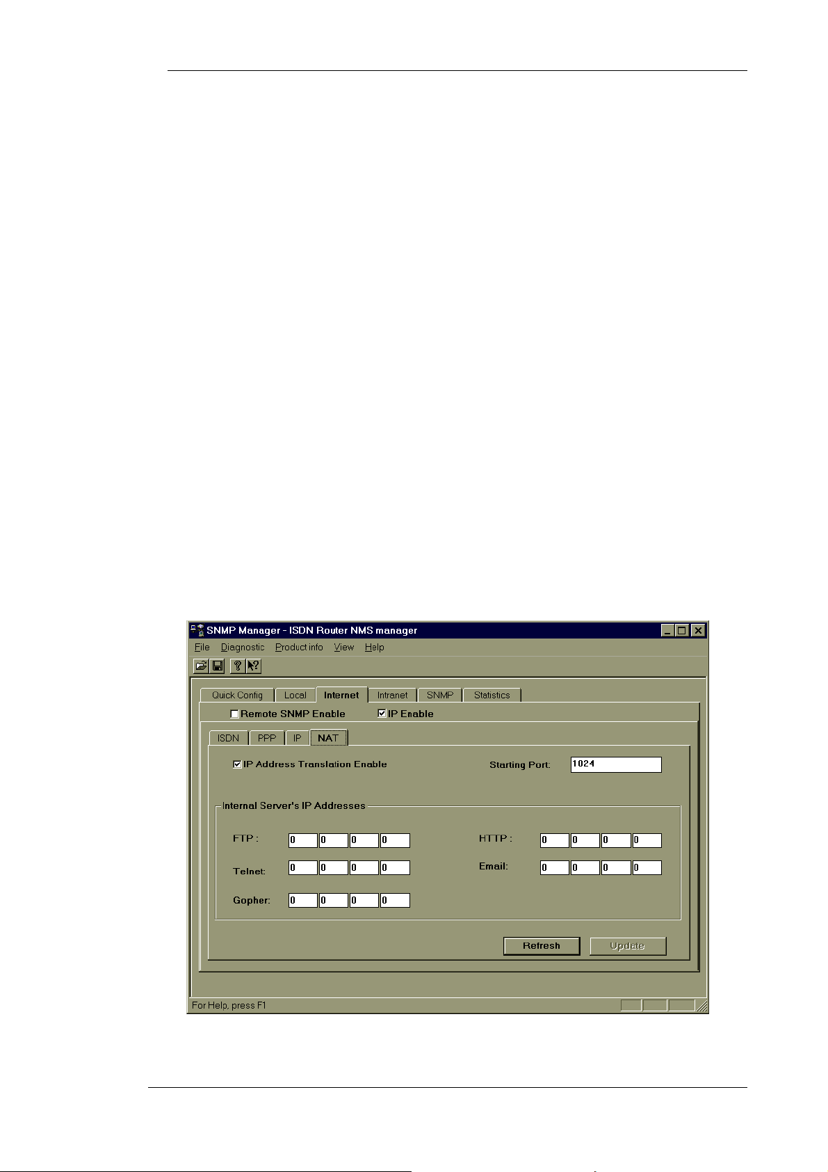
a
IP Mask of Remote Ethernet
The remote IP mask is used to describe the remote IP sub-netting. The IP mask is entered by clicking the
IP address bit map. The number of bits assigned for the IP subnet is shown next to the IP address bit map
as a decimal number, for your reference.
Local End IP Addre ss of ISDN Line
This field specifies the local end of the IP address of an IP connection. This field is applicable to the
“numbered interface” IP address setting.
Remote End IP Address of ISDN Line
This field specifies the remote end of the IP address of an IP connection. This field is applicable to the
“numbered interface” IP address setting.
IP Mask of ISDN L ine
This field specifies the IP mask of the ISDN line when the “numbered interface” IP address scheme is
used. Both local end and remote end should use the same IP mask.
Configur
Internet NAT Sub-menu
The Internet NAT sub-menu (see fig 4.12) is used to configure the NAT feature. NAT is a feature
designed for security protection and cost saving for Internet access. NAT hides internal IP addresses
from the outside world therefore decreasing the possibility of hacker attack. NAT translates the
internal IP addresses into a single IP address for Internet access. If the number of IP address assigned
by the ISP is a factor for billing, NAT can save the monthly bill.
Figure 0-10, Internet NAT Window
43
Page 51

a
Network Address Translation Enable
This field enables or disables the NAT function.
Starting Port
This field specifies the starting port number NAT would use to support the NAT function. 1024 is the
default port number.
FTP Server
The internal IP address of the FTP server that provides FTP service to the outside world. All incoming
FTP service requests are routed to the specified FTP server.
HTTP Server
The internal IP address of the HTTP server that provides HTTP service to the outside world. All incoming
HTTP service requests are routed to the specified HTTP server.
Telnet Server
Configur
The internal IP address of the Telnet server that provides Telnet service to the outside world. All incoming
Telnet service requests are routed to the specified Telnet server.
Email Server
The internal IP address of the Email server that provides Email service to the outside world. All incoming
Email service requests are routed to the specified Email server.
Gopher Server
The internal IP address of the Gopher server that provides Gopher service to the outside world. All
incoming Gopher service requests are routed to the specified Gopher server.
Intranet Menu
The Intranet configuration contains ISDN, PPP, IP, and IPX, sub-menus.
Intranet ISDN Sub-menu
The Intranet ISDN sub-menu is shown in Figure 0-11, Intranet ISDN Window. This window is used to
configure the ISDN connection for an Intranet access.
Re mote ISDN number
The remote ISDN number field specifies the ISP’s ISDN number you would like to dial to. Your ISP will
provide this number to you.
Data Service
The data service field is used to select 56 Kbps or 64 Kbps for the ISDN call bandwidth. 64Kbps is the
most common one. In rare situations such as international calls, 56Kbps may be the only choice.
44
Page 52
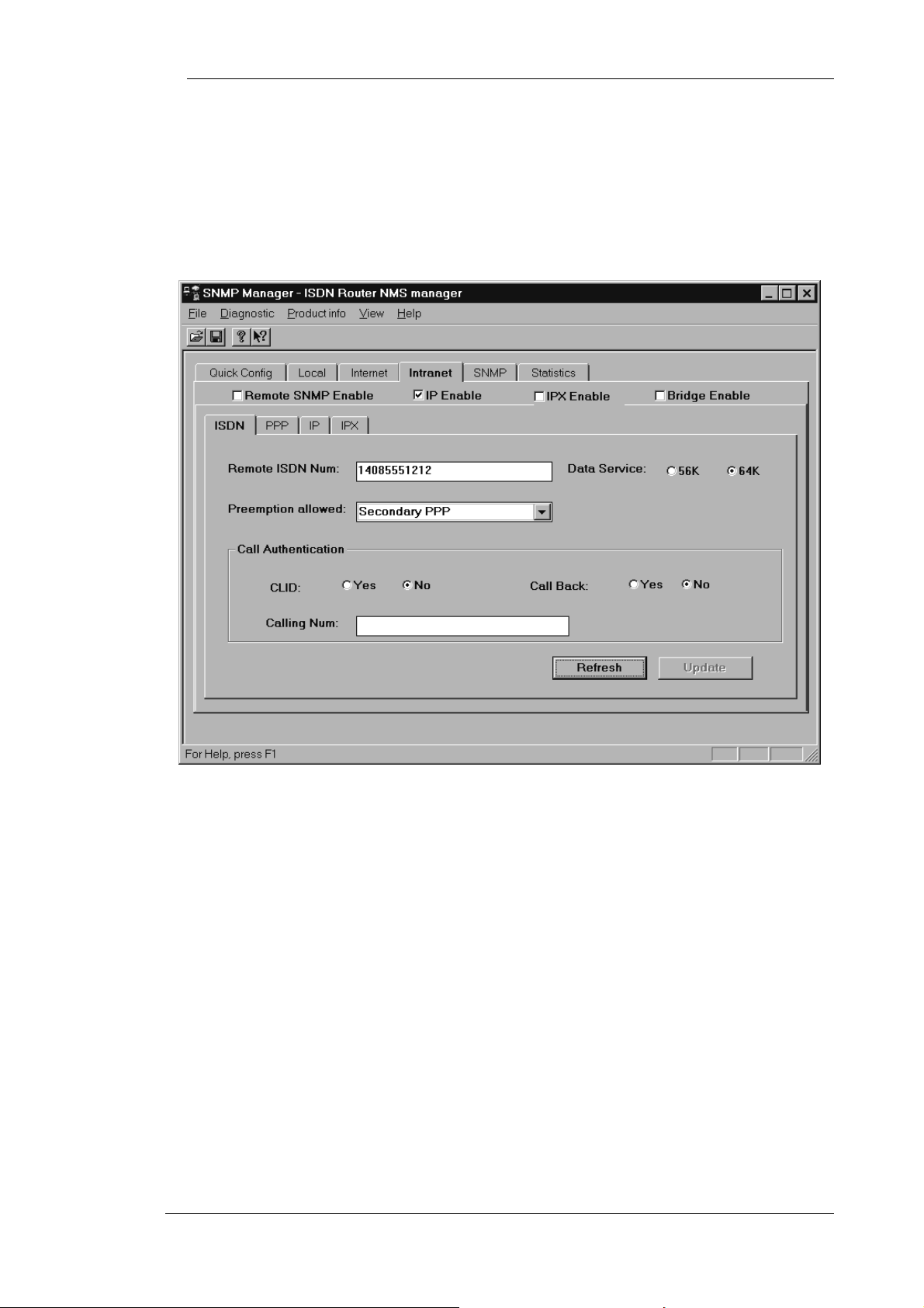
a
Preemption Allowed
This field is specified if the Internet connection is allowed to be preempted by a phone call or not, and in
what way. The Internet connection can be blocked from preemption at all, or be allowed on the 2nd PPP
only, or 1st PPP as well.
Configur
Figure 0-11, Intranet ISDN Window
CLID
Caller ID can be used to qualify the incoming call. Only the incoming call whose calling number matches
the CLID will be accepted. This is an Intranet feature. The data call will not be answered if the local
telephone company is not supplying the calling party number to the ISDN router. Please use with care.
Callback
Call back function is a security feature which enables the router to disconnect the incoming call upon
verification the CLID and call back to the CLID. This is an Intranet feature. And again the local telephone
company has to supply the calling party number to the ISDN router in order for this feature to work.
Calling Num
The number the router will call when the Callback function is enabled. This is an Intranet feature.
Intranet PPP Sub-menu
45
Page 53

a
The Intranet PPP sub-menu is shown in fig 4.14. This menu is used to configure the PPP parameters for an
Intranet connection.
Configur
Figure 0-12, Intranet PPP Window
Remote Router Name
The remote router name is the name assigned to the remote router located at the ISP end. Any visible
ASCII characters are acceptable. The remote router name is not required when you want to dial into your
ISP’s point of presence. In general, your ISP will assign you a remote IP address for administration
purpose.
Compression
The compression field specifies if the Stac compression protocol is to be used for the Internet
connection.
46
Page 54

a
Encapsulation Protocol
The encapsulation protocol field specifies the protocol you want to run as the link protocol. Select PPP if
you want to run single channel PPP. Select MLPPP if you intend to run two channel PPP when traffic
becomes heavy.
Dial-out Authentication
The dial-out authentication field specifies which protocol you want to run as the PPP/MLPPP
authentication protocol when you initiate an ISDN call to your ISP. Most ISPs support PAP and CHAP
protocols.
Dial-out Password
The dial-out password specifies the password to use during the dial-out authentication process. This field
is case sensitive, and is given to you b y your ISP.
Call-in Authentication
Configur
The call-in authentication field specifies which protocol you want to run as the PPP/MLPPP authentication
protocol when the ISP initiates an ISDN call to you. Under normal circumstances, your ISP would not
initiate a call to you.
Call-in Password
The call-in password specifies the password to use during the dial-in authentication process. This field is
case sensitive, and is gi ven to you by your ISP.
Ave Interval
The Average Interval specifies the period in seconds used for traffic measurement. A longer period (e.g.
greater than 30 seconds) causes the ISDN channel to be added or deleted in a slower but smoother pace. If
this parameter is set too short, the ISDN channel may be added due to a short burst of Internet traffic or be
deleted due to short idle period. Therefore, internally, the Ave Interval is set to minimum at 10 seconds.
This parameter is available only if the MP protocol is selected as the Internet encapsulation protocol.
1->2 Util
The 1->2 Utilization field specifies the Intranet connection traffic level beyond which the second ISDN
channel will be requested to enlarge the PPP bundle. The value range is from 0% to 100%. This parameter
is available only if the MP protocol is selected as the data encapsulation protocol.
47
Page 55
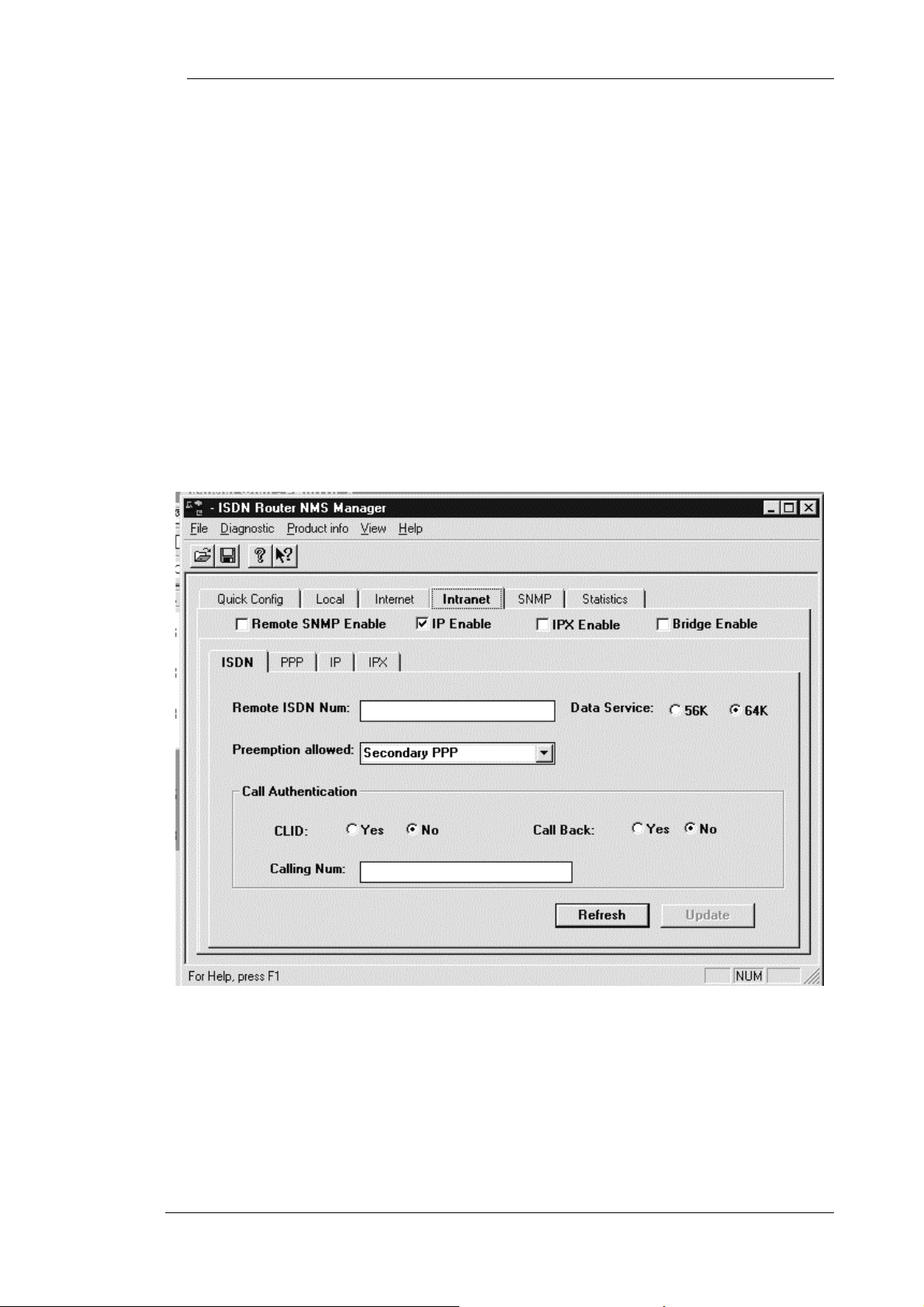
a
2->1 Util
The 2->1 Utilization specifies the Intranet connection traffic level; below which the second PPP channel
will be released from the PPP bundle. The value ranges from 0% to 100%. This parameter is available
only if the MP protocol is selected as the Internet encapsulation protocol.
1->0 Idle
The bandwidth management function will remove the (primary) Intranet connecti on when it is being
detected idle for a specific period. The 1->0 Idle parameter specifies the idle period in seconds. Assigning
0 second to this parameter has special meaning. It disables the 1->0 bandwidth management. The user has
to manually disconnect the Intranet Connection.
Intranet IP Menu
The Intranet IP sub-menu is shown in
Figure 0-13, Intranet IP Window. This menu is used to configure the IP related parameters of the
Intranet connection.
Configur
Figure 0-13, Intranet IP Window
Remote SNMP Enable
This check box is to enable or disable remote SNMP management. If disabled, the ISDN router will only
respond to the SNMP requests from the local Ethernet.
IP Enable
48
Page 56

a
This parameter is used to enable or disable the IP routing function. If IP routing is disabled, bridging
must be enabled for IP packets to be forwarded through the router. Bridging is rarely used as the
protocol for Internet access.
IP Address of Remote Ethernet
The remote IP address is the IP address of the remote router located at your ISP site. The IP address is
entered in the standard IP address format of a.b.c.d. The remote IP address is required during PPP
negotiation. Please ask your ISP if you don’t possess one.
IP Mask of Remote Ethernet
The remote IP mask is used to describe the remote IP sub-netting. The IP mask is entered by clicking the
IP address bit map. The number of bits assigned for the IP subnet is shown next to the IP address bit map
as a decimal number for your reference.
Local End IP Addre ss of ISDN Line
This field specifies the local end of the IP address of an IP connection. This field is applicable to the
“numbered interface” IP address setting.
Configur
Remote End IP Address of ISDN Line
This field specifies the remote end of the IP address of an IP connection. This field is applicable to the
“numbered interface” IP address setting.
IP Mask of ISDN L ine
This field specifies the IP mask of the ISDN line when the “numbered interface” IP address scheme is
used. Both local end and remote end should use the same IP mask.
Intranet IPX Menu
The Intranet IPX sub-me nu is shown in Figure 0-14, Int ranet IPX Window. This menu is used to
configure an IPX connection on an Intranet.
49
Page 57

Configur
a
Figure 0-14, Intranet IPX Window
RIP
The IPX RIP packets will always be exchanged over the WAN when the ISDN connection is up. The RIP
box when checked is to allow Netware RIP traffic to initiate the ISDN connection. This is not advised as
it will lead to unnecessarily high ISDN connection charg e s!
SAP
The IPX SAP packets will always be exchanged over the WAN when the ISDN connection is up. The
SAP box when checked will allow Netware SAP traffic to initiate the ISDN connection.
50
Page 58

a
Spoofing
The check box to enables or disables the IPX spoofing function. The spoofing function minimizes the
dial-up connection time by responding to the “keep alive” request on behalf of the remote IPX clients. The
spoofing function tries to minimize the ISDN dial-up against the IPX “keep alive” messages but does not
inhibit the the regular IPX or SPX messages.
Age
The IPX spoofing age configures how long the Hypertec Router will perform the spoofing function before
the ISDN dial-up is allowed by the “keep alive” message. Once the dial-up connection is up, the age timer
is reset.
IPX Route Table
An IPX rout e table entry contains IPX routing information for a known IPX network. The network number
identifies the unique IPX network. The gateway node is the node address for the gateway to that network.
The hop count indicates how far away the network is. The interface can be either local Ethernet or Intranet
through the ISDN connection.
Configur
For most applications, the user is not required to create or modify the IPX table.
IPX SAP Table
IPX SAP Table
An IPX SAP table entry contains information about a remote server. The server name is the name of
the server. The network is the internal network number of the server. The node number is the internal
node address of the server. The type is the service type of the server. The socket is the socket number
of the server. The hop count indicates the distance to the server. The NMS user is required to add a
SAP entry for every remote server the local clients intend to connect to. For a given SAP entry, the
Hypertec Router automatically adds a route entry in the IPX route table.
51
Page 59
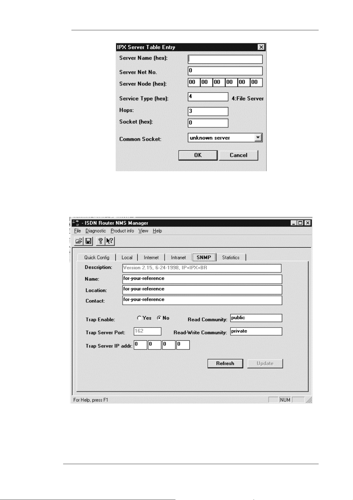
a
SNMP Menu
The SNMP menu (see Figure 0-15, SNMP Window) is used to configure the SNMP specific parameters.
Some of the parameters are corresponding to the objects defined in the system MIB. The rest are for
managing the SNMP access, and trap delivery
.
Configur
Figure 0-15, SNMP Window
52
Page 60

a
Description
The field gives a brief description of the product, as provided by the manufacturer.
Name
This field is used by the user to assign a name to this ISDN router.
Location
This field is used by the user to describe the location of this ISDN router.
Contact
This field is used by the user to describe the contact person for the ISDN router.
Read Community
This field is used to assign a “password” for SNMP read operation.
Configur
Read-Write Community
This field is used to assign a “password” for SNMP read-write operation.
Trap Enable
This parameter is used to enable or disable the trap delivery.
Trap Server Port
This parameter specifies which UDP port the traps are sent to.
Trap Server IP Address
This parameter specifies IP address where the traps are sent to.
Statistics Menu
Statistics Ethernet Sub-menu
The Statistics Ethernet sub-menu (see Figure 0-16, Statistics Ethernet Window ) contains the statistics data
collected on the Ethernet interface. Both directions of the traffic, receive and transmit, are monitored. .
The “refresh” button is used to collect a new page of statistics data. The “periodic on” button is used to
refresh this menu every second.
System Up Time
This is the time elapsed since the time the ISDN router has been powered-up, or reset.
Bytes
This counter displays the number of bytes the Ethernet has received or transmitted.
Frames
53
Page 61

a
This counter displays the number of frames the Ethernet has received or transmitted.
Broadcasts
This counter displays the number of broadcast frames the Ethernet has received or transmitted.
Configur
Figure 0-16, Statistics Ethernet Window
Errors
This counter displays the number of error frames the Ethernet has received or transmitted. The error
conditions are : too short, mis-alignment, excess collisio n.
54
Page 62
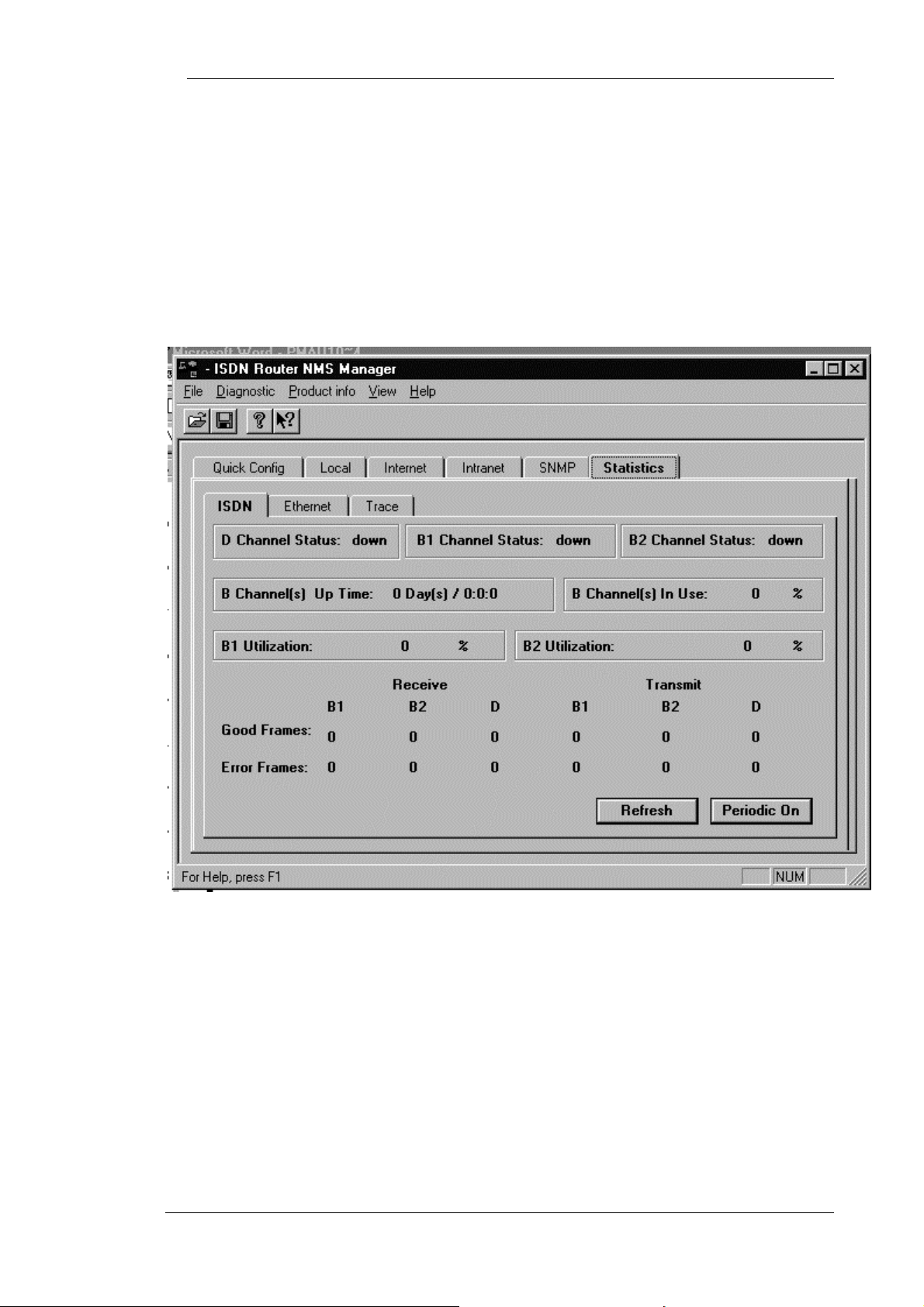
a
Discards
This counter displays the number of frames the Ethernet has discarded due to lack of buffer resource or
error detection..
Statistics ISDN Sub-menu
The Statistics ISDN menu (see Figure 0-17, Statistics ISDN Window) contains the statistics and status
data collected on the ISDN interface. The “refresh” button is used to collect a new page of statistics
data. The “periodic on” button is used to refresh this menu every second.
Configur
Figure 0-17, Statistics ISDN Window
D Channel Status
This field indicates the current D channel status. The D channel is either Up or Down.
B1 Channel Status
This field indicates the current B1 channel status. The B channel states are Up, Down, or Calling (in
the process of call establishment).
B2 Channel Status
This field indicates the current B2 channel status. The B channel states are in Up, Down, or Calling (in the
process of call establishment).
55
Page 63

a
B Channel(s) Up Time
This field display the time the ISDN channels, B1 or B2, have stayed up since last reset. Both channels up
for 1 minute is counted as 2 minutes.
B Channel(s) In Use
This field displays the percentage of time the B channel, B1 or B2, has stayed up since last reset. 50% in
use may mean one B channel is up all the time, and the other B is down all the time or both channels are
up for 50% of the time. 100% in use means both B channels are up all the time.
B1 Utilisation
This field displays the current B1 channel utilization, ranging for 0 to 100%. 0% means the channel is
currently idle. 100% means full 64 Kbps of the B channel bandwidth is busy in data traffic delivery.
B2 Utilisation
This field displays the current B2 channel utilization, ranging for 0 to 100%. 0% means the channel is
currently idle. 100% means full 64 Kbps of the B channel bandwidth is busy in data traffic delivery.
Configur
Good Frames
This field displays the number of good frames that are received or transmitted on the corresponding
channel.
Error Frames
This field displays the number of error frames received or transmitted on the corresponding channel. The
error conditions are : mis-alignment, or CRC error.
Statistics Trace Sub-menu
The Statistics Trace (see Figure 0-18, Statistics Trace Window) menu provides the trace information of the
ISDN router. This menu is the most useful menu for diagnostic purpose.
56
Page 64
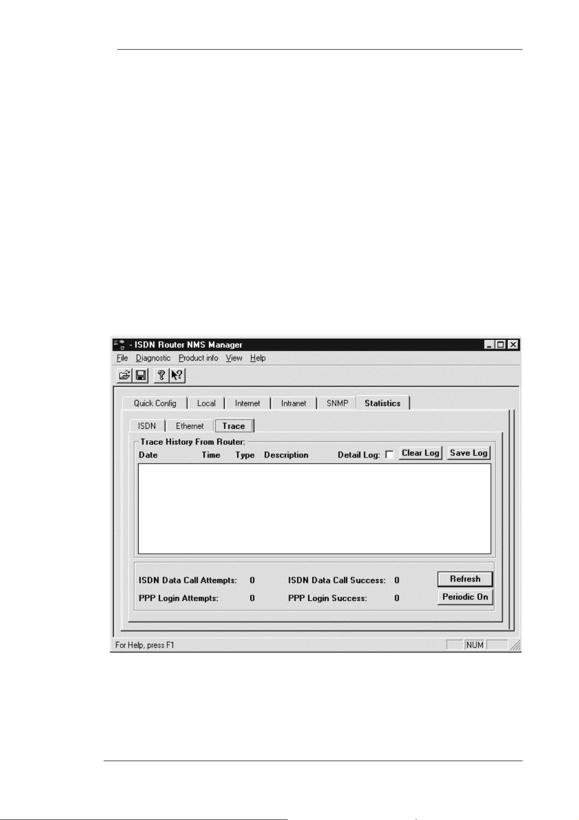
a
Trouble Shooting
Under the Detail Log, the trouble shooter enables the ISDN router to send more detailed IP, PPP, and
ISDN activity traps to NMS to enable trouble shooting. It should only be enabled during the trouble
shooting stage. Keeping it on all time will increase the Ethernet traffic, and work load to the ISDN router
and therefore is not beneficial to performance.
Clear Trap List
This click button is used to clear the traps previously stored in the trap histor y.
Detail Log Enable
This click button asks the Hypertec Router to send full detail traces. It is good source for trouble shooting.
At system reset time, the detail log is always disabled.
Trap History
Each trap is described in date, time, type, and a brief information about the cause of the traps. Within the
trap history area, up to 100 traps are stored for review with the most recent trap first.
Configur
Figure 0-18, Statistics Trace Window
ISDN Data Call Attempts
This field displays how many times the ISDN router has tried to make an ISDN data call since la st reset.
Note that an incoming ISDN data call does not contribute to this counter.
57
Page 65

a
ISDN Data Call Success
This field displays how many times the ISDN router has succeeded in making ISDN data calls since last
reset. Note that an incoming ISDN data call does not contribute to this counter.
PPP Attempts
This field displays how many times the ISDN router has tried to negotiate PP P d ata connections since
last reset.
PPP Success
This field displays how many times the ISDN router has succeeded in negotiating PPP data connections
since last reset.
Monitoring Status with ClearMo n.
ClearMon is a utility program which, while running, displays the Hypertec Router front panel
including real-time display of the LED status and activity lights. A typical ClearMon display is shown
in Figure 0-19, ClearMon Display
Configur
Figure 0-19, ClearMon Display
The top space will show the most recent trap received. You may click “History” to review old traps
maintained by ClearMon.
The virtual LED basically reflects what you would see on the Hypertec Router front panel. Under B1
and B2 vir tual LEDs, the “phone”, “Internet”(one networked PC), and “Intranet” (2 networked PC)
icons help to indicate if the B channel is used for voice, and data connection.
Managing the Hypertec Router from a Console
The Hypertec Router can be configured through an alphanumeric terminal (or a PC with a terminal
emulation program) which is used as a console by connecting it to the DB-9 connector on the Hypertec
Router rear panel. See Chapter 2, Installation for more details.
The terminal should be set to emulate a DEC VT100 terminal at 9600 bps with 8 character bits, no
parity bit and one stop bit.
The session can be started by pressing the Enter key a few times to display the login screen. A typical
login screen is shown in Figure 0-20, Console Login Screen. The example shown is one in which a PC
operating the Hyperterminal program is emulating a VT100.
58
Page 66
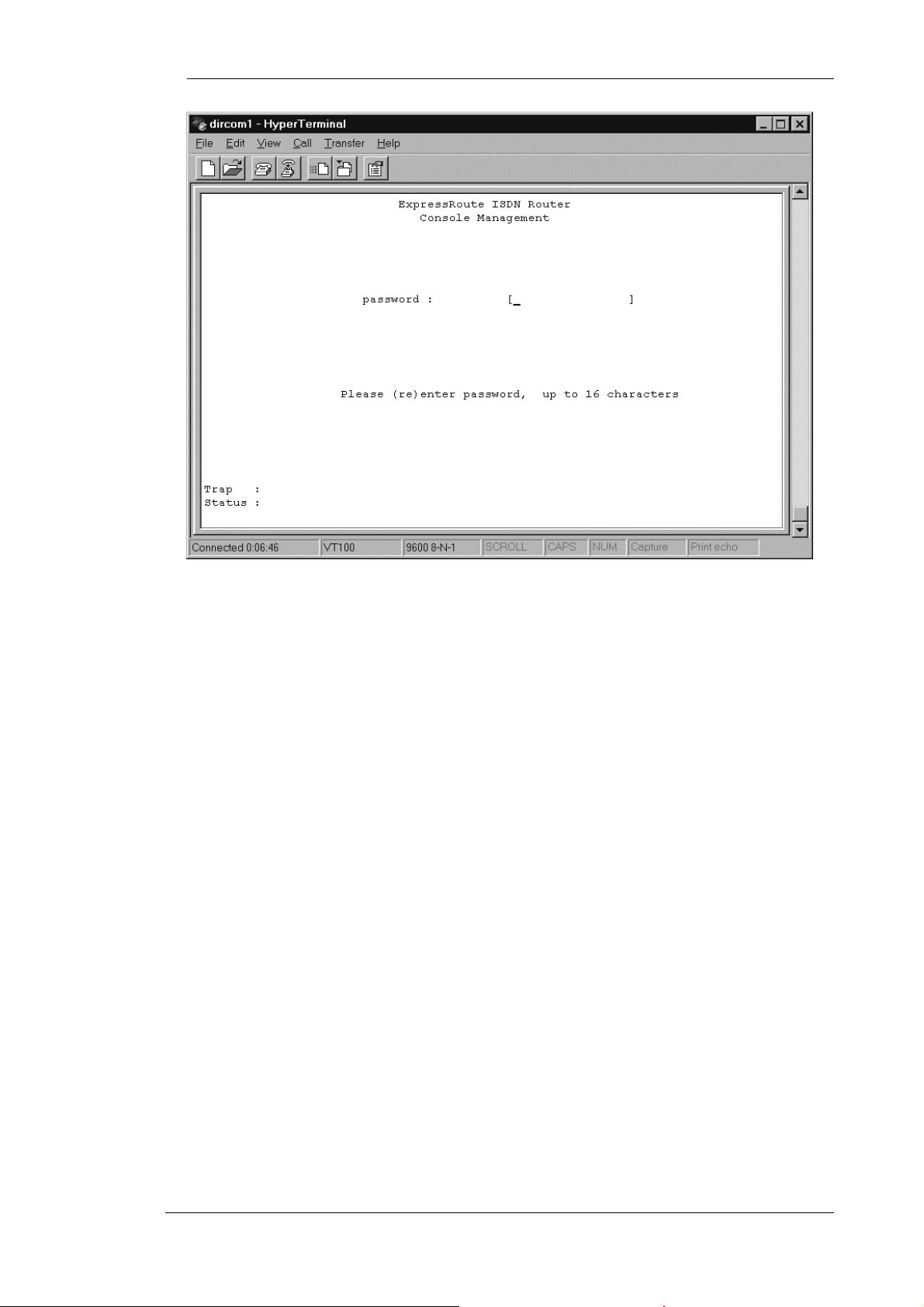
Configur
a
Figure 0-20, Console Login Screen
The login screen allows users to enter a password. The default password is “isdn”. Users are urged to
set up a new password, up to 16 alphanumeric characters, using “F2 Change User Password”.
When the password has been successfully entered, press the Enter key to display the console quick
config screen as shown in Figure 0-21, Console Quick Conf ig Screen.
59
Page 67
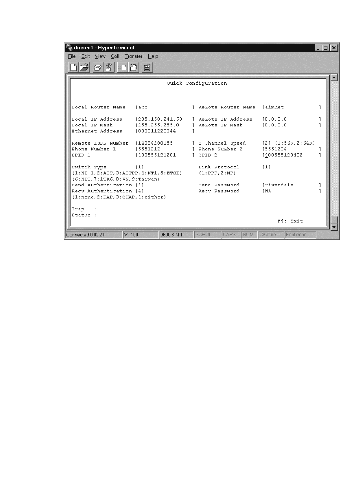
Configur
a
Figure 0-21, Console Quick Config Screen
The Console Quick Config screen permits the user to enter configuration data. Use the Tab key to
move to the next field and the Shift-Tab key to move to the previous field.
The Route Table data can be seen by pressing the F2 key and Statistics data by pressing the F3 key.
The F4 key is used to exit a screen.
Managing the Hypertec Router from a Browser
The Hypertec Router can be configured and managed from an attached Ethernet station using virtually
any standard Web Browser. The station must have the EasyWeb program installed as described in
Chapter 2.
Start the browser and enter the URL: http://<your web server name>/EasyWeb/login.htm. This will
cause the screen shown in Figure 0-22, EasyWeb SNMP Manager to be displayed.
Enter the IP Address and click on the Submit button.
Follow the instructions on the subsequent screens to configure and manage the Hypertec Router.
60
Page 68

Configur
a
Figure 0-22, EasyWeb SNMP Manager
Troubleshooting
This chapter explains how to isolate and resolve simple problems encountered with the Hypertec ISDN
Router. Problems may stem from incorrect configuration setting or improper installation. Follow the
following steps should help you resolve most of the symptoms. If problem persists, please contact
your technical support with a list of symptoms, LED display status.
PWR ALM B1 B2 D
ETHERNET
ISDN
Router
Figure 0-1, Front Panel LEDs
Express Route 80
61
Page 69

Troubleshooting
Troubleshooting Tips
Before you call technical support organization for assistance, check the following :
1. The power supply is connected and the power LED is on.
2. Turn the power off and on again, observe the alarm (ALM) LED
During power-up self-test, the ALM LED flashes.
If the ALM LED flashes and remains on for more than 10 seconds, there is an internal hardware
failure. Notify your reseller that the ISDN router has failed the self-test, and order a replacement.
If the LED goes off after the test has been completed, the power-up self-test has been successful.
3. Verify that the ISDN cable (RJ45, 8 pin position) is connected to the ISDN router and make
sure that it is an ISDN connection, not a plain old telephone connection.
The ISDN router will not operate if connected to an analog telephone wall jack. If your ISDN
router is equipped with U interface, make sure that the ISDN router is connected directly into the
ISDN wall outlet. If your ISDN router is equipped with a S/T interface, make sure that the ISDN
router is connected to an intermediate telephone device called NT-1.
62
Page 70

Troubleshooting
4. Monitor the status of the D channel LED
When you are connected to a live ISDN line, the D channel LED will be lit or flashing.
If the D channel LED remains off, it indicates that no ISDN signal present. It is likely that there
is a poor connection to the local telephone company. Make sure that the ISDN cable is in good
condition, and securely plugged-in. If the LED remains off, call your local telephone company
for trouble shooting assistance. The problem may be the ISDN link cable, or the telephone
company equipment.
If the D channel LED flashes, there is probably a mismatch between the settings of the ISDN line
and the ISDN router configuration. Check the switch type setting, and SPIDs (Northern
America). If the D channel LED does not lighted on after these verification, call your reseller for
line configuration and troubleshooting assistance.
If the D channel LED remains on, it indicates a valid communication channel has been
established and calls may be attempted by the user. The D channel LED should remain on all the
time until there is problem on the ISDN line or signaling.
5. Monitor the status of the B channel LEDs
There are two B channel LEDs : B1 LED and B2 LED B1 indicate your ISDN channel activities.
If the B channel LED is off, it indicates that the B channel is in idle state. If the B channel LED is
lighted on, the associated B channel is in use. It can be used for data connection or
voice/fax/modem connection.
6. Monitor the status of the Ethernet LEDs.
There are four Ethernet LEDs, each designated for an Ethernet Port.
If an Ethernet LED is lighted on, it indicates that there is an Ethernet device connected to the
associated Ethernet port transmitting valid Ethernet signal. If the Ethernet LED is off, either no
Ethernet device is connected at the remote end, or there is a problem with the Ethernet UTP cable
(RJ45) or with the Ethernet Network Interface Card (NIC).
An Ethernet LED will blink when there are Ethernet frames transmitted to or received from that
Ethernet device. The Ethernet LED indicates the presence of Ethernet traffic but not the volume
of the Ethernet traffic.
7. If your are unable to communicate with the router through console port
The ISDN router is designed to communicate with a VT100 terminal all time. If you are unable
to communicate with the router, make sure the RS232 cable is a 9-pin male to female straightthrough cable, and the baud rate is set to 9,600 baud per second.
63
Page 71

Troubleshooting
8. If your are unable to communicate with the router through NMS.
The Network Management System (NMS) communic ates with the router through Ethernet using
the SNMP protocol. If your NMS is unable to get SNMP response from the router, check the
following :
Ping a known active station in the local Ethernet. If you are unable to receive the ICMP
response, you may have problem with your TCP/IP installation. Chec k the NMS Ethernet cable,
NIC, and T C P/IP configuration.
If you are abl e to ping othe r TCP/IP stations but not t he ISDN router. Make sure t hat the ISDN
router is active, and it is assigned with the correct IP address.
9. If your are unable to make voice call
If you are unable to make a voice call when there is no B channel or only one B channel is in use
as indicated by the B channel LEDs. Check the RJ11 telephone cable and the analog device
itself.
10. If your are unable to make a data call
This is a more complicated problem than any of the previous list. It is suggested that you use
NMS statistics, and trace utilities to help you perform the diagnosis. The NMS trace utility show
you the network activities in detailed. The NMS statistics give you detailed LAN and WAN
frame count.
If you are sending traffic towards an Internet or Intranet, but the B channel LED or trace window
shows no ISDN activities. You should check your IP network configuration.
If the ISDN router fails at the ISDN dialing attempt, check the telephone number configured.
The number has to be one associated with an ISDN data device at the remote end. The trace
windows should provide you with the precise error message.
If the ISDN call is connected briefly for a few seconds, and then disconnected. Mostly likely
your PPP configuration mismatches the remote end. Check your PPP configuration including PPP
authentication protocol, and password.
Index
1
1->0 Idle.............................................. 4-20, 4-29
1->2 Utilization...................................4-20, 4-28
2
2->1 Utilization...................................4-20, 4-28
A
access list...................................................... 4-15
Analog Services features................................ 1-3
ARP Proxy.................................................... 4-15
average interval...................................4-20, 4-28
B
bandwidth-on-demand.................................. 3-11
B-channel alarm threshold............................ 4-12
bridging.......................................................... 3-4
browser management....................................4-42
C
call ID ...........................................................4-25
call-back........................................................4-25
Callback........................................................3-13
Caller ID ..............................................3-13, 3-20
call-in authentication.................. 4-10, 4-20, 4-28
call-in password......................... 4-10, 4-20, 4-28
calling number ..............................................4-25
Challenge Authentication Protocol.................3-9
CHAP..............................................................3-9
community
read ....................................................4-35
read-write...........................................4-35
compression.................................4-9, 4-19, 4-26
Concepts & Principles of Operations..............3-1
configuration and management.......................4-1
Connection Profile..........................................3-4
Console management ....................................4-40
64
Page 72

Index
contact.......................................................... 4-35
D
data compression.......................................... 3-12
data service field..................................4-18, 4-24
data usage..................................................... 4-14
device name.................................................. 4-11
dial-on-demand............................................. 3-11
dial-out authentication.........4-9, 4-10, 4-20, 4-28
dial-out password................4-9, 4-10, 4-20, 4-28
directory number............................................ 3-2
Dynamic IP address Assignment.................... 3-7
E
Email server.................................................. 4-24
encapsulation protocol..................4-9, 4-19, 4-27
Ethernet features............................................. 1-3
EZ-ISDN...................................................... 3-19
F
FTP server.................................................... 4-24
G
IP mask of remote ethernet...........................4-30
IP mask of the ISDN line..............................4-23
IPX frame type..............................................4-12
IPX network..................................................4-12
ISDN Capability Packages..........................
ISDN features .................................................1-2
ISDN Line Provisioning ...............................3-15
ISDN Order Codes........................................3-17
ISDN Overview ..............................................3-1
ISDN Permanent connection services.............3-3
ISDN switch type...................................4-9, 4-10
ISDN variant...................................................3-1
3-17
L
LCP.................................................................3-8
Link Control Protocol (LCP............................3-8
local
Ethernet Sub-Menu............................4-11
IP sub-menu.............................4-14, 4-16
ISDN sub-menu .................................4-12
local end IP address of ISDN line........4-22, 4-30
local IP address...............................................4-8
local IP mask...................................................4-8
local router name.............................................4-7
login in NMS ..................................................4-6
general description ......................................... 1-1
Gopher server............................................... 4-24
H
HTTP server................................................. 4-24
I
installation
E80 NMS.............................................2-4
EasyWeb..............................................2-4
general.................................................2-1
hardware.............................................2-1
software...............................................2-3
Internet
IP sub-menu.......................................4-21
ISDN sub-menu.................................4-17
NAT sub-menu..................................4-23
PPP sub-menu....................................4-19
Internet features.............................................. 1-3
Intranet
IP sub-menu.......................................4-29
IPX sub-menu....................................4-30
ISDN sub-menu.................................4-24
PPP sub-menu....................................4-26
IP address..............................................3-5, 4-11
IP address of remote Ethernet....................... 4-30
IP address translation enable................. 4-9, 4-23
IP enable.............................................. 4-21, 4-29
IP mask......................................................... 4-11
IP mask of ISDN line................................... 4-30
M
menu
quick configuration.............................4-7
Multilink PPP..................................................3-9
Multiple Subscriber Numbering (MSN).......3-20
N
NAT..............................................................3-14
Network Aaddress Translation...............4-9, 4-23
Network Management features.......................1-3
Network Translation (NAT) ..................3-7, 3-14
NMS................................................................4-2
login.....................................................4-6
menu structure......................................4-2
starting.................................................4-6
System Menus......................................4-4
toolbar..................................................4-5
windows...............................................4-3
NT1 interface..................................................3-1
numbered/unnumbered IP addresses...............3-6
P
packet filtering..............................................3-13
PAP.................................................................3-9
Password Authentication Protocol (PAP) .......3-8
phone 1 usage................................................4-14
phone 2 usage................................................4-14
Phone Number 1............................................4-9
Phone Number 2............................................4-9
4
Page 73

Index
phone number-1............................................ 4-13
phone number-2............................................ 4-14
Point-to-Point Protocol (PPP) ........................ 3-8
PPP................................................................. 3-8
preemption allowed............................. 4-18, 4-24
Provisioning ISDN....................................... 3-15
Q
quick configuration menu............................... 4-7
R
Rate Adaptation.............................................. 3-3
remote end IP address of ISDN line....4-22, 4-30
remote IP address......................................... 4-21
remote IP mask............................................. 4-22
remote ISDN number...................4-8, 4-18, 4-24
remote router name.......................4-7, 4-19, 4-26
remote SNMP enable...........................4-21, 4-29
Required Information.................................... 4-5
RIP protocol................................................. 4-15
route table..................................................... 4-14
Router Software features................................ 1-3
routing............................................................ 3-4
enable.................................................4-35
IP address...........................................4-35
server port..........................................4-35
Solution Sets...............................................
SPID 1............................................................4-9
SPID 2..........................................................4-10
SPID-1 ..........................................................4-13
SPID-2 ..........................................................4-13
spoofing ........................................................4-31
starting port...................................................4-24
statistics
3-19
Ethernet sub-menu.............................4-35
ISDN sub-menu .................................4-36
Trace sub-menu..................................4-38
subnet mask.....................................................3-5
switch type....................................................4-12
T
Telnet server .................................................4-24
terminal types................................................3-21
U
uninstalling NMS...........................................2-4
S
S/T interface................................................... 3-1
Security features............................................. 1-3
Service Profile Identifier (SPID).................... 3-2
SNMP trap
V
voice preemption...........................................3-15
5
Page 74

Product Warranty
Hypertec Limited warrants the hardware components of the product to be in good working order for
the life of the product from the date of purchase of the product from Hypertec or an authorised
Hypertec dealer. Should the hardware components of the product fail to be in good working order at
any time, Hypertec will, at its option, repair or replace the product.
Repair parts and replacement products will be furnished on an exchange basis, a nd will be either
reconditioned or new. All replaced parts will become the property of Hypertec.
This warranty applies only to the original registered end user purchaser of the product and does not
include service to repair damage resulting from accident, disaster, misuse, abuse or non-Hypertec
modification of the product.
Additional components installed by the dealer or end user are not covered by this warranty. Apart
from the above, no warranty is expressed or implied, including warranty of merchantability or
warranty of fitness for use for a particular purpose.
The liability of Hypertec is limited to the repair or replacement of the product with a functionally
equivalent or better product. Hypertec is not liable for any accidental, general, special, exemplary or
consequential damages resulting from any product failure, even if Hypertec has been advised of the
possibility of such damages.
Index
Hypertec Limited
Units 1-3 Station Road
Hungerford, Berkshire RG17 0DY
Ph: +44 (0)1488 686844
Fax: +44 (0)1488 686845
Web: www.hypertec.co.uk
Email: sales@hypertec.co.uk
4
 Loading...