

Page 1
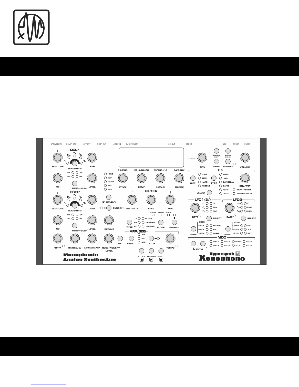
XENOPHONE
Rev 1.0
Reference Manual
WWW.HYPERSYNTH.COM
Page 2

XENOPHONE Reference Manual - - - - - - - - - - - - - - - - - - - - - - - - - - - - - - - - - - - - - - - - - - - - - - - - HYPERSYNTH
3
3
3
4
6
7
7
9
10
11
14
15
16
19
21
21
26
Table of Contents
ABOUT THIS MANUAL - - - - - - - - - - - - - - - - - - - - - - - - - - - - - - - - - - - - - - - - - - - - - - - - - -
SIGNAL FLOW - - - - - - - - - - - - - - - - - - - - - - - - - - - - - - - - - - - - - - - - - - - - - - - - - - - - - - - - -
SYNTH ENGINE - - - - - - - - - - - - - - - - - - - - - - - - - - - - - - - - - - - - - - - - - - - - - - - - - - - - - - -
OSCILLATOR 1 - - - - - - - - - - - - - - - - - - - - - - - - - - - - - - - - - - - - - - - - - - - - - - - - - - - - - - - -
OSCILLATOR 2 - - - - - - - - - - - - - - - - - - - - - - - - - - - - - - - - - - - - - - - - - - - - - - - - - - - - - - - -
OSCILLATOR 3 , NOISE GENERATOR - - - - - - - - - - - - - - - - - - - - - - - - - - - - - - - - - - - - - -
VOICE - - - - - - - - - - - - - - - - - - - - - - - - - - - - - - - - - - - - - - - - - - - - - - - - - - - - - - - - - - - - - - -
MIXER - - - - - - - - - - - - - - - - - - - - - - - - - - - - - - - - - - - - - - - - - - - - - - - - - - - - - - - - - - - - - -
FILTER - - - - - - - - - - - - - - - - - - - - - - - - - - - - - - - - - - - - - - - - - - - - - - - - - - - - - - - - - - - - -
ENVELOPES - - - - - - - - - - - - - - - - - - - - - - - - - - - - - - - - - - - - - - - - - - - - - - - - - - - - - - - - -
LFO 1,2,3 - - - - - - - - - - - - - - - - - - - - - - - - - - - - - - - - - - - - - - - - - - - - - - - - - - - - - - - - - - -
MAIN - - - - - - - - - - - - - - - - - - - - - - - - - - - - - - - - - - - - - - - - - - - - - - - - - - - - - - - - - - - - - - -
ARPEGGIATOR/SEQUENCER - - - - - - - - - - - - - - - - - - - - - - - - - - - - - - - - - - - - - - - - - - - -
MODULATION MATRIX - - - - - - - - - - - - - - - - - - - - - - - - - - - - - - - - - - - - - - - - - - - - - - - - -
APPENDIX A – MIDI IMPLEMENTATION CHART - - - - - - - - - - - - - - - - - - - - - - - - - - - - -
APPENDIX B – MIDI CC/NRPN TABLE - - - - - - - - - - - - - - - - - - - - - - - - - - - - - - - - - - - - -
APPENDIX C – SPECIFICATIONS - - - - - - - - - - - - - - - - - - - - - - - - - - - - - - - - - - - - - - - - -
2
Page 3
XENOPHONE Reference Manual - - - - - - - - - - - - - - - - - - - - - - - - - - - - - - - - - - - - - - - - - - - - - - - - HYPERSYNTH
ABOUT THIS MANUAL
This manual assumes that you have some knowledge about subtractive synthesizers, so it does not go
into depth of certain concepts such as how Filter, LFO or ENV work in detail, although the unique
features are described here briefly. There are plenty of resources for information about the theory of
sound synthesis. For more information about Connections, Basic Operation, Global settings, Saving,
loading and renaming patches please refer to Quick Start guide.
SIGNAL FLOW
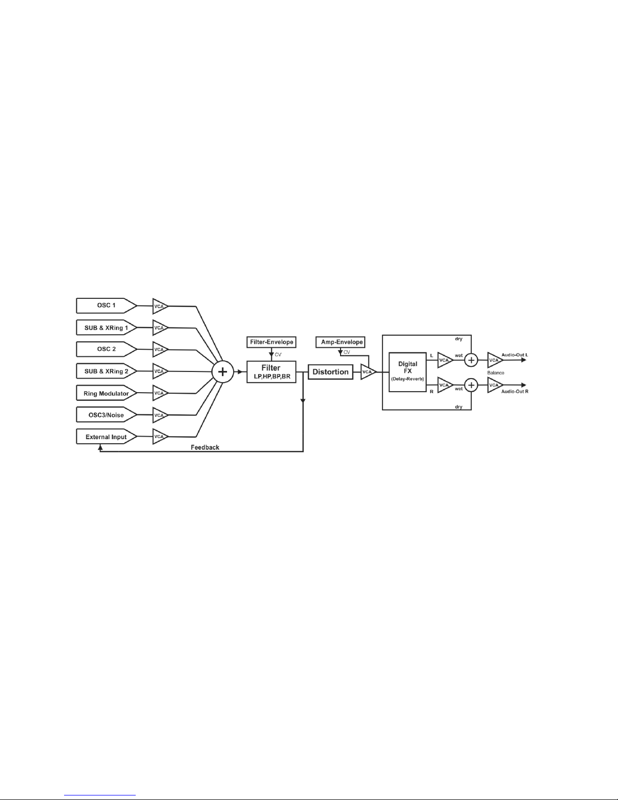
Xenophone’s signal path is 100% analog. This means that Oscillators, VCAs, Mixer, Filter and Distortion
are based on analog circuits and there is no D/A (digital to analog converter) in signal path. Except for
Digital FX which can be muted and leave the analog signal untouced. DFX stereo outputs are injected to
a pair of VCAs and then mixed with the master VCA output signal.
SYNTH ENGINE:
Xenophone is an analog subtractive synth while it follows a modern semi modular architecture. The
engine is customized in way to provide the important functions via hardwired connections and at the
same time giving you the option to route your own signals via Modulation Matrix. The synth engine
consists of 16 parts. Each part has several parameters which can specifically alter the sound shape,
pitch, timber and color. These parts are categorized in two groups: Audio and Mod.
Audio Group: Oscillator1, Oscilaltor2, Noise Generator/Oscillaotor3, Mixer, Filter, Main
Mod Group: Voice, Amplitude Envelope, Filter Envelope, Modulation Envelope, LFO1, LFO2, LFO3,
Arpeggiator, Sequencer, Mod Matrix.
Audio group includes parts that are basically the source of the sound or affect the sound shape or color
directly. The Audio group parameters are controlled by CVs “Control Voltages” that are generated by
Mod group. The Mod group parts do not generate any sound but produce control voltages to modulate
the Audio group parameters. Mod group can also modulate themselves via Modulation matrix. All these
16 parts are described one by one in the next pages of this manual.
3
Page 4
XENOPHONE Reference Manual - - - - - - - - - - - - - - - - - - - - - - - - - - - - - - - - - - - - - - - - - - - - - - - - HYPERSYNTH
Waveform
Description
Saw
Sawtooth
Sqr
Square
Tri
Triangle
SawSqr
Combined Saw and Square
TriSqr
Combined Triangle and Square
Off
Disconnects oscillator from the mixer, reduces background noise
StpSqr
Combined Square and Square (Stepped Square)
Xor1-2
Ring Modulation between oscillator 1 and 2 square wave
OSCILLATOR 1
Semitone: [-60…+60] sets oscillator base frequency over 10
octaves from C-1 to C9: 8Hz-8Khz (C4 is the middle C)
Cent: [-50…+50] fine tune the base frequency; 0 centered.
(50 cents = 1/2 semitone). (Soft Knob E3)
Keytrk: [on, off] enables/disables keyboard tracking for oscillator. For
regular playing it must be on. When [off], the oscillator frequency is
fixed and does not follow the played keys. (Soft Knob E4)
Waveform: see table:
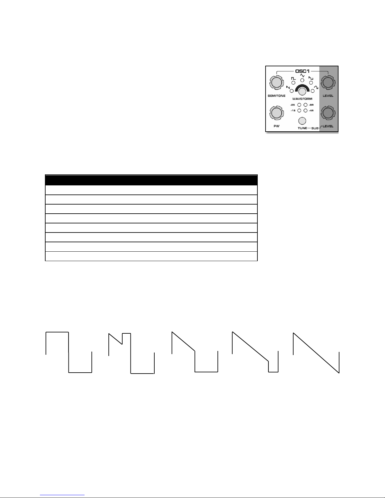
Saw, Square and Triangle are the classic waveforms. Xenophone oscillators are purely analog and not
wavetable based but they can produce new waves out of the classic ones using waveshaper circuit.
These new waves are called combined waveforms:
SawSqr is build from Saw and Square in time domain (not Amplitude). Using Shape parameter you can
morph between these two waveforms like the following example:
Shape 0 Shape 50 Shape 100 Shape 150 Shape 200
Besides Shape value the pulse width setting can also change the Square wave independently which
results in creating of more complex and unpredictable waveforms with rich harmonics. Don’t forget to
tweak the shape and pw to find the sweet spots. You can modulate the shape and pw at the same time
too.
4
Page 5
XENOPHONE Reference Manual - - - - - - - - - - - - - - - - - - - - - - - - - - - - - - - - - - - - - - - - - - - - - - - - HYPERSYNTH
XOR ring modulator is a kind of analog ring modulator that only receives square wave as input,
the output is square wave and result of the input multiplication. It has been used in many vintage
synths like Arp, Korg and etc.
XOR function is internally hardwired, after selection it automatically gets a square wave from OSC
2 while other waveforms can be selected on OSC2 at the same time. Except the OSC 2 Pitch other
settings do not affect the Xor funtion like: waveform, Oscillator level, etc.
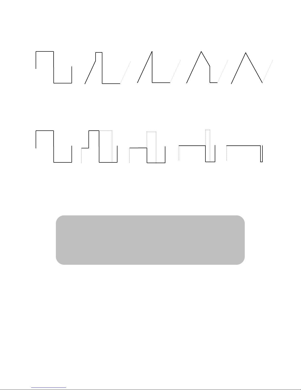
TriSqr has the same concept while it is built from a Triangle and Square wave:
Shape 0 Shape 50 Shape 100 Shape 150 Shape 200
StpSqr is a kind of square wave with double steps while the Pulse Width parameter only affects one
part. However, you can get a virtual PWM on the second part with modulating Shape:
Shape 0 Shape 50 Shape 100 Shape 150 Shape 200
Xor1-2: When it is selected, it replaces oscillator 1 output with “ring modulated” combination of
oscillators 1 and 2 square waves. Varying the frequency of oscillator 1 with respect to oscillator 2
produces a wide range of non-harmonic overtones useful for creating crunchy and gritty sounds.
PW: [0…200] determines the amount of Pulse Width for Square waveform.
Shape: [0…200] alters the wave shape for combined waveforms: SawSqr, TriSqr, StpSqr. (Soft Knob E4)
Phase: [0…127] sets the start phase for oscillator. It makes sense when at least two oscillators are used
in the patch (Soft Knob E4). See Phase Mode (page 4)
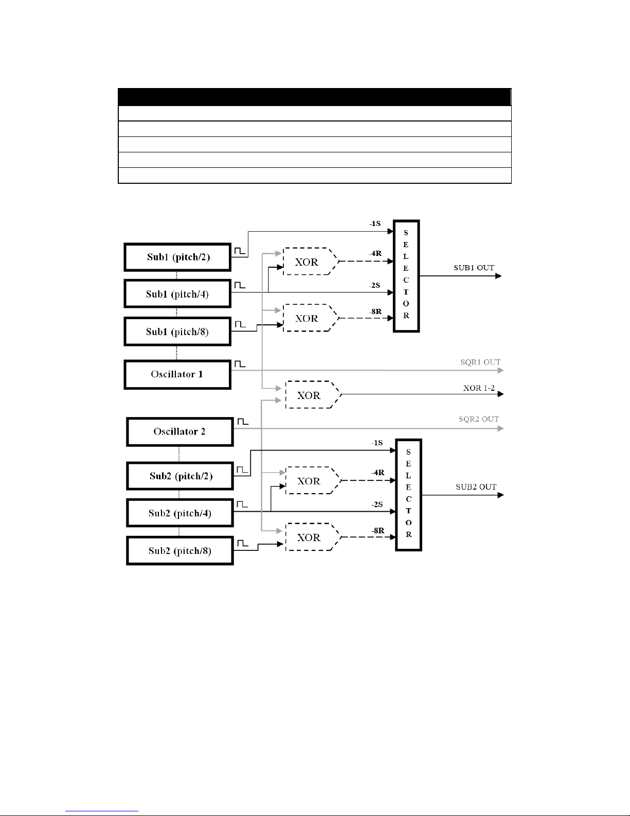
Subtype: [-1 Oct, -2 Oct, -4Ring, -8Ring, Off] each oscillator has a dedicated sub oscillator which can be
tuned 1 or 2 octave below the base frequency. Sub oscillator output is a square wave with 50% PW. The
sub output can be replaced by ring modulated combination of oscillator 1 and its sub which is tuned 2 or
4 octaves below the base. The ring modulator is XOR based and only accepts square wave, all signal
connections are hardwired internally like the following picture.
5
Page 6
XENOPHONE Reference Manual - - - - - - - - - - - - - - - - - - - - - - - - - - - - - - - - - - - - - - - - - - - - - - - - HYPERSYNTH
Sub Mode
Description
-1 Oct (-1S)
Sub Oscillator pitch : ½ base freq
-2 Oct (-2S)
Sub Oscillator pitch : ¼ base freq
-4 Ring (-4R)
Xor Ring =X*Y (X=oscillator signal , Y= sub oscillator ¼ base freq)
-8 Ring (-8R)
Xor Ring =X*Y (X=oscillator signal , Y= sub oscillator 1/8 base freq)
Off
Disconnects Signal from the mixer and reduces background noise
OSCILLATOR 2
All parameters of oscillator 2 are the same as oscillator 1. The Xor 1-2 is only available for oscillator 1
and not for oscillator 2 waveform.
6
Page 7
XENOPHONE Reference Manual - - - - - - - - - - - - - - - - - - - - - - - - - - - - - - - - - - - - - - - - - - - - - - - - HYPERSYNTH
Porta Type
Description
Legato Fixed
Portamento will occur only if you play a second key before lifting up the first key.
Always Fixed
Portamento always occurs regardless of the situation of the next keys.
Legato Scaled
Portamento will occur only if you play a second key before lifting up the first key.
Always Scaled
Portamento always occurs regardless of the situation of the next keys.
C64 type is a pitched noise which can be played by keyboard. it is like a lo-fi white noise while its
harmonics are emphasized by the base frequency of Oscillator 3. This type of noise is inspired from
the famous SID chip noise generator section that was found in old Commodore 64 game console.
When you modulate the pitch of the oscillator 3 it also affects the C64 noise pitch.
OSCILLATOR 3 / NOISE GENERATOR
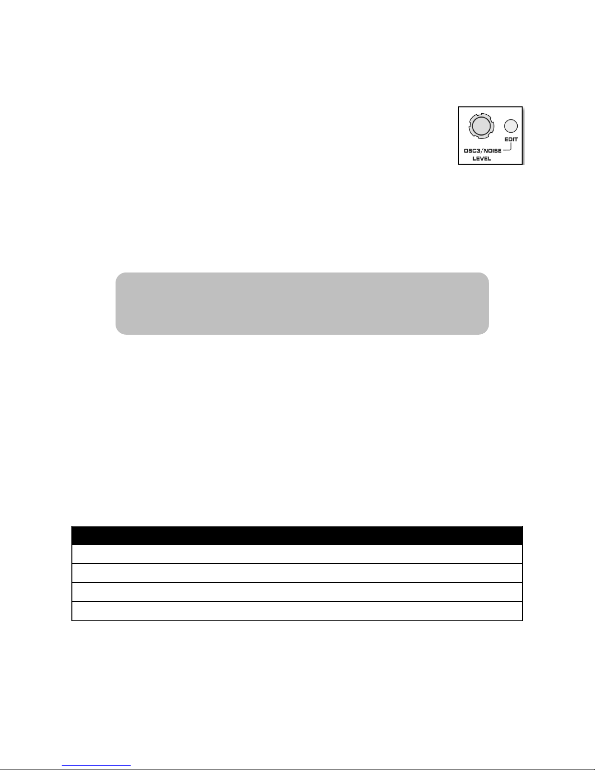
Oscillator 3 waveform is limited to Square wave. Oscillator 3 output and Noise
generator share a single VCA, you can only use and select one of them. The noise
generator module can produce standard White, Pink, Red and C64 noise.
Semitone: [-60…+60] sets oscillator 3 and pitched noise base frequency over 10
octaves from C-1 to C9: 8Hz-8Khz (C4 is the middle C) (Soft Knob E2)
Noise Type: [white, Pink, Red, C=64, SQR] determines the noise type or replaces the output with
Oscillator 3 signal. (EDIT Button)
Keytrk: [on, off] enables/disables keyboard tracking for the oscillator 3. (Soft Knob E4)
VOICE
Porta: [0…127] determines the Portamento/Glide time. Porta LED=On shows that the portamento time
is more than zero.
The portamento time can be fixed or scaled. In Fixed mode Portamento time is fixed regardless of the
distance between two played keys. In Scaled mode it is variable and represents the amount of time it
takes to glide a distance of one octave. For example if the distance between the first and the second key
is two octaves, the portamento time will be double.
Porta Type: see table.
Bend Range: [0…24] Determines how many semitones the incoming pitch wheel data can bend the
pitch of the oscillators. If you set it to zero, the pitch wheel will have no direct effect on the pitch,
although it can still be used in the Mod Matrix as a source of the modulation.
7
Page 8

XENOPHONE Reference Manual - - - - - - - - - - - - - - - - - - - - - - - - - - - - - - - - - - - - - - - - - - - - - - - - HYPERSYNTH
Analog drift is an algorithm which emulates the analog circuit components tolerance, temperature
effect and power supply noise. These flaws caused instability and tuning issues in old analog
synthesizers that used voltage based pitch control system. On the other hand and in a magical way
these flaws have a significant role in warmth and fatness of the sound when more than one
oscillator is used in the patch.
Voic:Dtune FM* Drft
* 0 740 26
Detune: [0…50] sets the amount of detuning between the three oscillators. The detune function
increases oscillator 1 pitch and decreases oscillator 2 pitch from 1 cent to 50 while leaves the oscillator 3
pitch untouched.
FM: [0…1022] sets the amount of FM depth, Zero means
disable. (Coarse Soft Knob E1, Fine E3)
FM is located in Voice section Page2. [E3] soft knob changes
value ±1 step and [E1] changes it ±10 steps.
Oscillator 2 Triangle signal always modulates oscillator 1 frequency (you cannot change the modulator
waveform here it is hardwired internally). Varying the pitch of oscillator 2 regarding FM depth will result
in frequency modulation of oscillator 1. Except the pitch, other settings of oscillator 2 does not affect on
FM function. For the best result Square should be selected as waveform in oscillator 1.
Drift: [0…127] sets the amount of Analog Drift. (Soft Knob E4)
Although the Xenophone’s oscillators are analog but the main pitch is controlled by a microprocessor
(based on digital tuning word not voltage) which makes the synth always in tune. Analog drift detunes
and modulates oscillators in micro-cents range. If you want to hear the effect of analog drift you should
use more than one oscillator and set the [Phase Reset] parameter to Free-run.
Sync: [Off, On] enables/disables Hard Sync. It synchronizes fundamental frequency of oscillator 1 with
frequency of oscillator 2, producing a “hard sync” effect. In order for synchronization to occur oscillator
2 must be set to some frequency preferably lower than the frequency of oscillator 1.
Phase Reset: [On, Free-run] when “on” forces oscillators to start at specific phase (usually zero) every
time a new note is played. Each Oscillator has a dedicated phase parameter that represents the starting
point in waveform. If OSC1 Phase and OSC2 Phase have the same value, [Phase Reset = On] forces them
to be phase synced. In some sounds like percussive or bass it helps to increase punch and overall audio
level specifically when the waveforms and settings on both oscillators are the same. (Soft Knob E3)
In Free-run mode the oscillators are working freely and the Note-On message does not reset the phase.
In most of the analog synths, oscillators are working in Free-run mode. You can get the best result for
creating vintage synth sounds and fat brasses Using Free- run mode + Analog drift at the same time.
8
Page 9
XENOPHONE Reference Manual - - - - - - - - - - - - - - - - - - - - - - - - - - - - - - - - - - - - - - - - - - - - - - - - HYPERSYNTH
OSC1 SUB1 OSC2 SUB2
54 0 53 127
RING FEED/EXT OSC3
11 0 23
Clipping: Like other analog mixers, Xenophone mixer has the potential to clip the output If the summation of the
input signals exceeds a certain level (clipping level). For example if you set OSC1, OSC2, SUB1 and SUB2 levels all to
127 you should not expect clip-less signal at the output. A good starting point for input levels is 64. If you hear
clipping in a patch, the first thing you should do is decreasing the levels of oscillators, subs, ring, ext and noise.
Beside the mixer, increasing the Feedback level and high resonance on 24db filter can also clip the signal. The
solution is only reducing the source levels or resonance amount.
MIXER
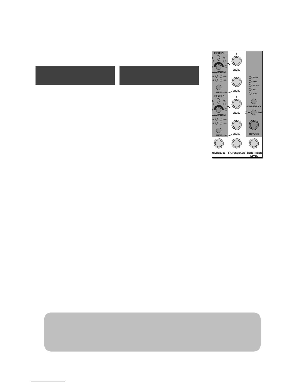
The Xenophone mixer has seven inputs that are categorized in two
pages on the display:
OSC1 Level: [0…127] Determines oscillator 1 level.
SUB1 Level: [0…127] Determines sub oscillator 1 level.
OSC2 Level: [0…127] Determines oscillator 2 level.
SUB2 Level: [0…127] Determines sub oscillator 2 level.
Ring Level: [0…127] Determines analog ring modulator level. Ring modulator
gets the oscillator 1 and 2 audio signal as input and multiplies the levels and
polarity of these signals. Varying the pitch of oscillator 1 or 2 will generate
various non-harmonics overtones at ring modulator output while keeping
fundamental frequencies of the inputs. Ring modulator is useful for creating
metallic and bell type sounds.
EXT/Feedback: [0…127] Determines “External Audio Level” or “Feedback Amount”. You can use only
one function regarding the connection of external TRS jack.
For processing external audio with filter and DFX you can inject an external audio signal into the
Xenophone input located at the back panel. Note that for hearing the audio the Amp Envelope must be
open this means that you must play a note or set the [Amp Env Release] to maximum value (Hold). A
pre-configured patch for this purpose is located in factory Bank0-Program122: MSC-Ext Audio 1.
When external jack is disconnected, Xenophone uses its path for injecting post-filter signal into the
mixer regarding the feedback level. Increasing feedback adds warmth and overdrive to the sound
besides it decreases resonance amount, when filter is set to LP or serial modes. For HP, BP and notch it
increases resonance.
Warning: Using feedback with level higher than 50 may cause self-oscillating with massive level at the
output, in order not to harm your ears and speakers use this parameter with care.
OSC3 Noise Level: [0…127] Determines oscillator 3 or Noise Generator level.
9
Page 10
XENOPHONE Reference Manual - - - - - - - - - - - - - - - - - - - - - - - - - - - - - - - - - - - - - - - - - - - - - - - - HYPERSYNTH
Filter Type
Self-Oscillating region
Self-Oscillating Wave
LP/HP -24dB
Res= 96…100
Sinus
18dBLP > 6dBHP
Res= 57…100 (scream)
Triangle
12dBLP > 6dBHP
Res = 57…100 (scream)
Clipped Triangle
Filter Type
Description
Available Slopes
LP
Low-Pass
-12dB, -18dB, -24dB
HP
High-Pass
-12dB, -18dB, -24dB
BP
Band-Pass
-12dB
Notch
Notch Filter
-12dB
18LP>6HP
Serial LP > HP 1
-24dB
12LP>6HP
Serial LP > HP 2
-18dB
EnvD Freq Res Ktrk
-25.2 1055 63 +67
Fltr:Type SLOPE FM
LP 18dB off
FILTER [VCF]
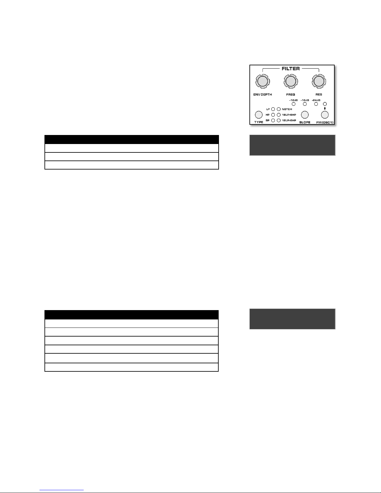
ENV Depth: [-50.0…+50.0] sets how much the filter envelope
modulates filter frequency.
Freq: [0…4095] sets the filter cut off frequency.
Res: [0…100] sets the filter resonance level. The 24dB and serial
filters self-oscillate at high resonance level. See table:
The table is valid only when the Feedback level is zero, non-zero feedback
level alters the resonance amount.
Keytrk: [-100…+100] sets how much the filter frequency tracks
the keyboard. For example, it makes filter frequency higher as
you play higher notes on the keyboard or lower as you play
lower notes. The keyboard tracking signal is the summation of
MIDI note number, portamento and pitchbend signal. A setting
of [0] means the keytracking have no effect on the filter
frequency. A setting of [+100] means the filter cutoff will follow
the keyboard pitch at a 1:1 ratio centered around C4 (MIDI note
60). (Soft Knob E4)
Type: Sets the filter type. see table:
Slope: [-12dB, -18dB, -24dB] sets filter slope. see table above.
FM(OSC1): [Off, On] enables audio rate modulation for filter
frequency via oscillator1. When [FM=On] oscillator1 signal will
be disconnected from the mixer.
10
Page 11
XENOPHONE Reference Manual - - - - - - - - - - - - - - - - - - - - - - - - - - - - - - - - - - - - - - - - - - - - - - - - HYPERSYNTH
History Feature: Xenophone remembers the last edited envelope and shows it by blinking related LED. Thus you
can switch back to the last tweaked envelop only by pressing [ENV] button one time. (For example, imagine the
display shows “Mod Env” page when you use [freq] knob to change filter frequency the display will jump to Filter
edit-page and the “Mod Env LED” start blinking, showing that you can switch back to Mod Env by pressing ENV
button again)
UI-Fixed Mode: As you can only edit envelops with soft-knobs, this feature allows you to edit envelops parameters
and other synth parts at the same time without screen jump. It temporarily enables/disables the “Display Mode =
Fixed”, while you are tweaking envelops in “Display Mode = Jump”. For enabling UI-Fixed mode, press [enter]
button in envelop edit-page, then the screen will be locked to env edit-page while you can change other
parameters at the background. For disabling it, press [enter] again.
ENVELOPES
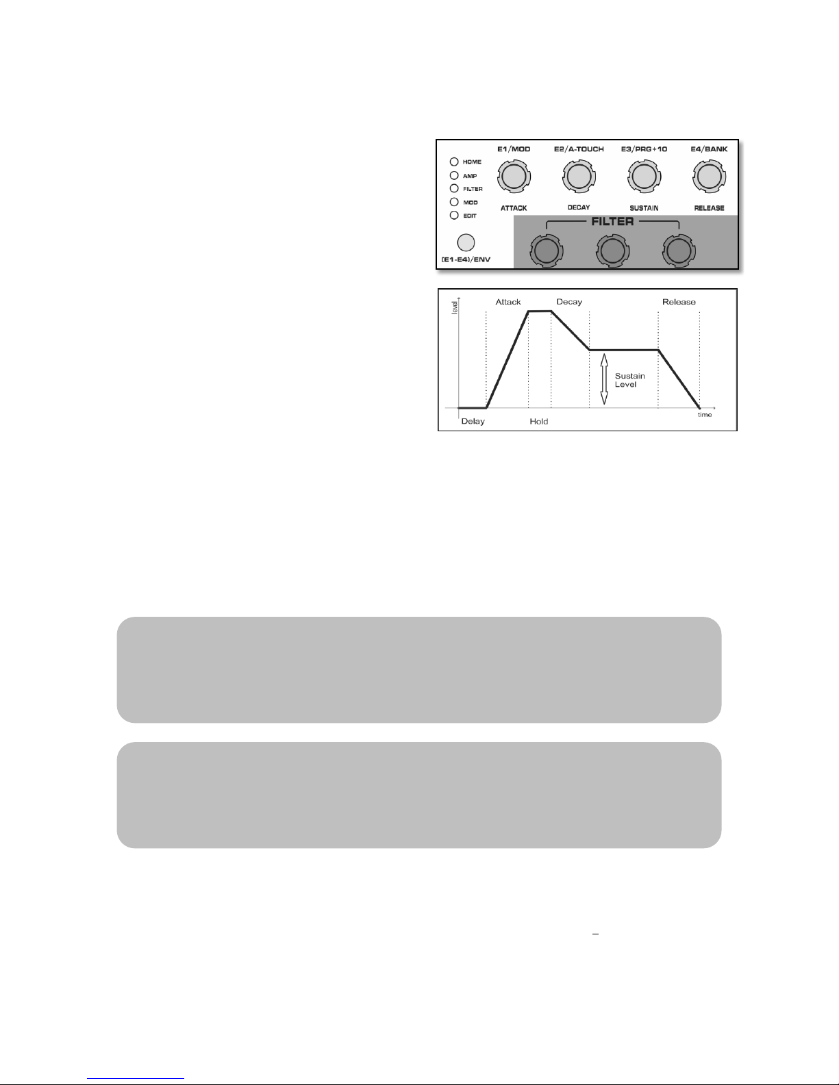
Xenophone has 3 envelopes: Amp, Filter and
Mod. Amp ENV is connected to the master VCA
and Filter ENV is connected to the VCF. Mod
ENV is an auxiliary envelope. All three
envelopes are available as mod source in modmatrix.
Unlike the regular 4 stage ADSR envelopes, here
envelopes have 6 stages DAHDSR:
Delay, attack, decay, hold, sustain, release.
The delay stage provides adjustable wait time
after the envelope trigger, which is useful for
creating delayed-vibrato effect.
The Hold stage freezes the envelope signal level after the attack stage that can be used for increasing
punch in percussive sounds with fast attack and decay. Filter and Mod envelopes have 6 stages, but the
Amp envelope has 5 stages (without delay).
How to change envelopes settings?
Using [E1-E4/ENV] button you can select the envelope edit pages and edit the parameters by soft knobs.
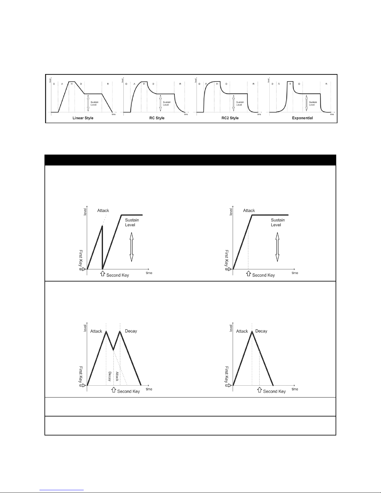
Envelope Style: Besides stage timing, the envelope architecture has a significant role in shaping
and forming the output signal of the envelope. Xenophone features 4 envelopes styles and you can set
different style for each envelope. Linear style is what you can found in most of the digital synths that
has its own linear character. The RC style is based on the vintage envelope design that follows
11
Page 12
XENOPHONE Reference Manual - - - - - - - - - - - - - - - - - - - - - - - - - - - - - - - - - - - - - - - - - - - - - - - - HYPERSYNTH
Trigger Mode
Trigger Mode
Always: Always starts from the beginning of the
attack stage.
Legato: For the first key it forces the envelope to start
from the beginning of the attack stage, For the second
key it continues from the current state/level of the
envelope.
Analog1: Always starts the attack stage from the
current level of the envelope without reset to zero
level. It makes sense when long decay or release
time is used.
Analog2: It is the legato version of Analog1.
LFO2SH: Forces the envelope to start from the beginning of the attack stage at each clock cycle of LFO2 when
S&H is selected as waveform.
#FootP: Forces the envelope to start from the beginning of the attack stage, only after receiving MIDI Foot
Pedal message CC#64.
exponential curve of capacitor charge/discharge voltage. RC2 is like RC1 with steeper curve and
Exponential style uses negative slope for attack stage.
Envelope Trigger: Determines where your envelope starts when you play notes:
12
Page 13
XENOPHONE Reference Manual - - - - - - - - - - - - - - - - - - - - - - - - - - - - - - - - - - - - - - - - - - - - - - - - HYPERSYNTH
A:250mS S:100 P1>
D:1mS R:1.02S Amp
< Amp Env P2>
Velo:100 Hold:1ms
< Amp Env P3>
Stl:Lin Trig:Always
A:250mS S:100 P1>
D:1mS R:1.02S Flt
< Filter Env P2>
Dly:1ms Hold:1ms
< Filter Env P3>
Stl:Lin Trig:Legato
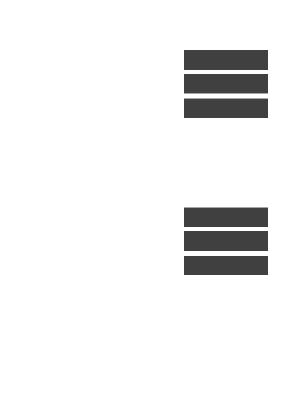
AMPLITUDE ENVELOPE (AHDSR)
Attack: [1mS…29.9S] sets attack time for Amp Envelope.
Decay: [1mS…29.9S] sets decay time.
Sustain: [0…100] sets sustain level.
Release: [2mS…29.9S] sets release time.
Velo: [0…127] sets velocity amount. (Soft Knob E1)
Hold: [1mS…29.9S] sets hold time. (Soft Knob E3)
Stl: [Lin, RC, Exp] sets the envelope style. (Soft Knob E1)
Trig: [Always, Legato, Analog1, Analog2] sets the trigger
mode. (Soft Knob E3)
loop: when [release = 0] the loop function is enabled this means that the envelope will continuously
switch back to the beginning of the attack stage after finishing the decay cycle.
Hold: when [release > 29.0S] it will force the envelope to be opened even without receiving the note-on
message. This feature is useful when you want to hear the external audio without playing a key on the
keyboard.
FILTER ENVELOPE (DAHDSR)
Attack: [1mS…29.9S] sets attack time for Filter Envelope.
Decay: [1mS…29.9S] sets decay time.
Sustain: [0…100] sets sustain level.
Release: [2mS…29.9S] sets release time.
Delay: [0…127] sets delay time. (Soft Knob E1)
Hold: [1mS…29.9S] sets hold time. (Soft Knob E3)
Stl: [Lin, RC, RC2, Exp] sets the envelope style. (Soft Knob E1)
Trig: [Always, Legato, Analog1, LFO2S&H, Analog2, #FootP] sets the trigger mode. (Soft Knob E3)
loop: when [release = 0] the loop function is enabled this means that the envelope will continuously
switch back to the beginning of the attack stage after finishing the decay cycle. In this case the envelope
can be used as LFO with an unusual waveform.
MOD ENVELOPE (DAHDSR)
MOD envelope parameters are the same as filter envelope.
13
Page 14
XENOPHONE Reference Manual - - - - - - - - - - - - - - - - - - - - - - - - - - - - - - - - - - - - - - - - - - - - - - - - HYPERSYNTH
SNC RATE1 WAV DEPTH
off 02.06 Tri +22.0
LFO1 Target Reset
none Frrun
LFO1
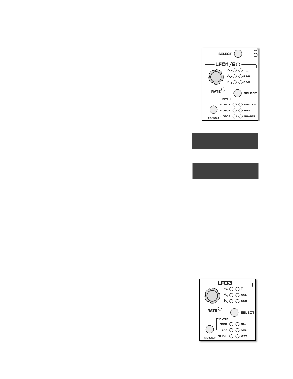
Rate: [0.00…99.90 Hz] sets the LFO frequency.
Sync: [On, Off] when on, The LFO rate can be controlled with note
values between 1/2 and 1/32 notes. The rate is then dependent
on the tempo setting. (Soft Knob E1)
Waveform: sets the LFO waveform:
[Sinus, Tri, Saw, Sqr, Sample & Hold, Sample & Glide]
Depth: [-100.0…+100.0] sets LFO depth. Depth represents the
modulation depth at the same time you can set the LFO with
different depth in mod-matrix slot. The depth range covers 1
octave when OSC1/2/3 pitch is selected. (Soft Knob E4)
Target: sets the modulation target for LFO1:
[none, Oscillator 1 Pitch, Oscillator 2 Pitch, Oscillator 3 Pitch,
Oscillator 1 level, Oscillator 1 PW, Oscillator 1 Shape]
OSC1/2/3 options can be selected at the same time.
Reset: [Always, Legato, Freerun] sets LFO reset behavior regarding
the played notes. “Always” forces the LFO waveform to start at
zero phase after receiving each note-on message. “legato” only
resets the LFO signal for the first key. “Free-run” never resets LFO.
(Soft Knob E4)
LFO2
For quick accessing to LFO2 settings you can use the [select] button. LFO2 does not have independent
modulation targets, other parameters are the same as LFO1.
LFO3
All parameters of LFO3 are the same as LFO1, except the mod targets:
[none, Filter Freq, Filter Resonance, Noise Level, Main Balance,
Main Volume, DFX Wet Level]
14
Page 15
XENOPHONE Reference Manual - - - - - - - - - - - - - - - - - - - - - - - - - - - - - - - - - - - - - - - - - - - - - - - - HYPERSYNTH
Type
P0 [0…200]
P1 [0…200]
P2 [0…200]
Room
Pre-delay
Reverb Time
Damp
Hall
Pre-delay
Reverb Time
Damp
Cathedral
Pre-delay
Reverb Time
Damp
Gated
Pre-delay
Reverb Time
Damp
Plate
Time
LF Response
HF Response
Delay
Left Delay
[0-1000 ms]
Right Delay
[0-1000 ms]
Delay + Reverb
Delay
[0-690 ms]
Repeats
Reverb
Ping Pong
Delay
Left Delay
[0-500 ms]
Right Delay
[0-500 ms]
Repeats
Sync L-dly R-dly Rep
On 1/8 !1/4 101
Main:Wet Bal Vol
51 0 120
Main:DFX Dist
PngPong Light
MAIN
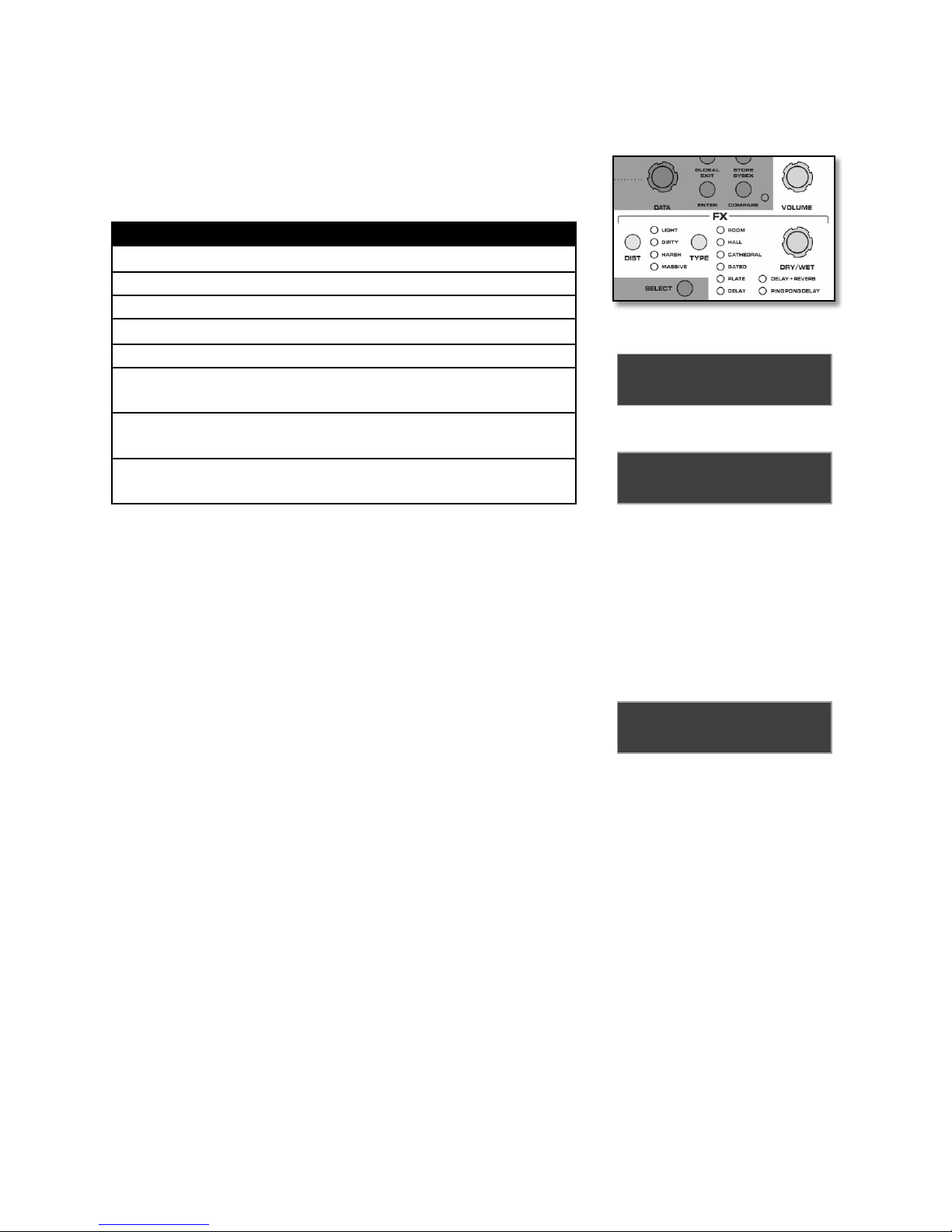
DFX type: sets digital FX type. DFX has three parameters: P0, P1, P2.
These parameters are different for every algorithm: (Soft Knobs E2-4)
Sync: [On, Off] when on, DFX delay time can be controlled with note values between 1/2 and 1/32
notes. The rate is then dependent on the tempo setting. If the selected synced rate for Px is more than
the maximum delay length of the algorithm, it will be marked with an exclamation point “!” on the
screen showing that you must switch to a shorter delay time. (Soft Knob E1)
Distortion: [Light, Dirty, Harsh, Massive] sets the distortion type.
Dry/Wet: [0…127] sets how much the DFX wet (processed) signal is
added to the dry (unprocessed) signal. “0” means 0% Wet (no
effect).
Balance: [-50…+50] sets the amount of balance between Left and
right outputs. (Soft Knob E3)
Volume: [0…127] sets the amount of main volume (program level).
15
Page 16
XENOPHONE Reference Manual - - - - - - - - - - - - - - - - - - - - - - - - - - - - - - - - - - - - - - - - - - - - - - - - HYPERSYNTH
Arp :Div Gate Tempo
1/32t 90 120.5
Arp :Span Range Latc
Up 3 oct off
step 1 4 8 12 16
ARPEGGIATOR/SEQUENCER
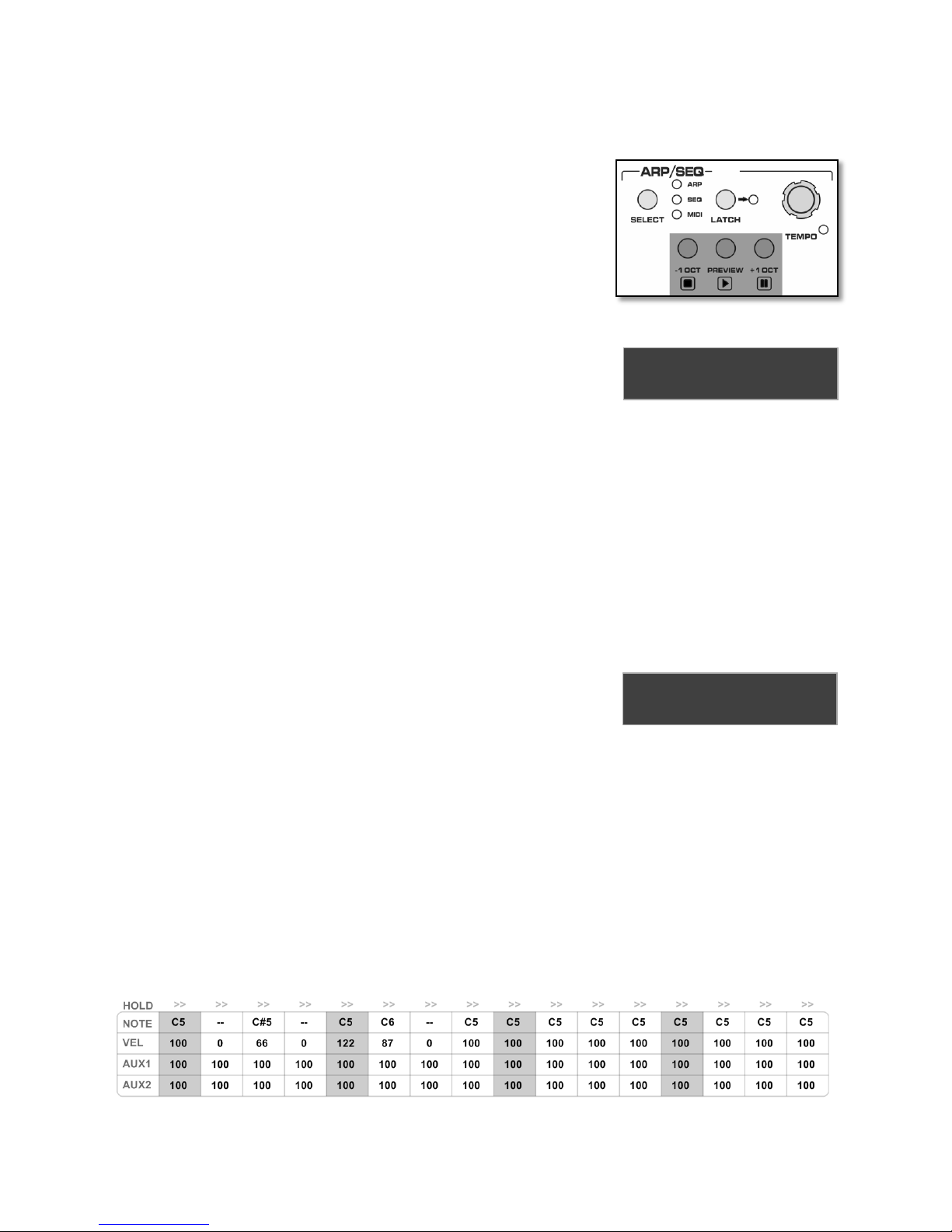
Using The [Select] button you can access the arp/seq edit pages.
The clock settings are shared between the arpeggiator and
sequencer. Arpeggiator and sequencer cannot be used at the same
time. The “Span” option determines which one of them is active.
For both modules, the “gate” value defines note length.
Arpeggiator settings:
Div: [1/32 , 1/16 , 1/8 , 1/4 , 1/2 , 1/32d, 1/16d, 1/8d, 1/4d,
1/2d, 1/32t , 1/16t , 1/8t , 1/4t , 1/2t] sets the duration between
two notes and thus defines the speed, at which the notes are
played. “D” stands for dotted and “T” is for triolic note lengths. (Soft
Knob E2)
Gate: [0…127] defines the gate signal duration. Gate represents the
length of each note. When the gate is set to 64, the length of each
note is half of the time between two successive notes. (Soft Knob E3)
Tempo: [50.0…250.0 bpm] sets the master tempo. Tempo controls
arp/seq speed, LFOs synced rates and DFX synced delay. (fine tune: Soft
Knob E4)
Span: [Off, Up, Down, Up/Down, Step] when off arp/seq function is
off. Up, Down and Up/Down define the arp melodic order. Step
activates sequencer and deactivates arpeggiator. (Soft Knob E2)
Range: [1...3 octave] determines over how many octaves the notes
are spread. (Soft Knob E3)
Latch: [Off, On] When on, latch LED is lit and notes played on the
keyboard will continue to arpeggiate after the keys are released.
The latch function also works when arp/seq is off. (latch button)
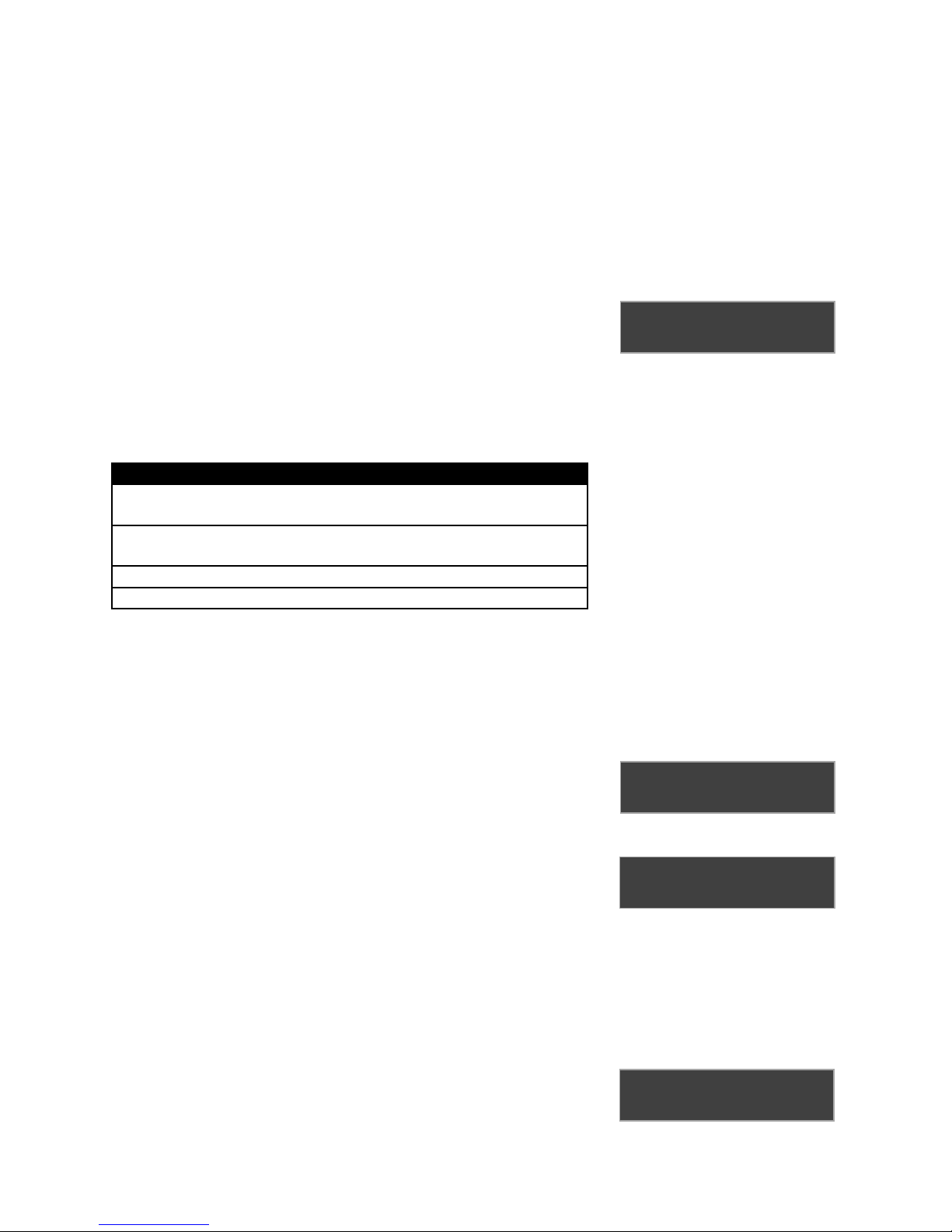
Sequencer: can be configured to function as 4 x 16 “analog-style” step sequencer or 4x16 “digital
style” Step-LFO:
16
Page 17
XENOPHONE Reference Manual - - - - - - - - - - - - - - - - - - - - - - - - - - - - - - - - - - - - - - - - - - - - - - - - HYPERSYNTH
Trigger Mode
Description
Key-RST
Sequencer always starts from the first step for each played
note.
No-Reset
Sequencer keeps playing notes from the last step, every time a
new note is played.
Stp-LFO
Free running Step-LFO without reset to first step.
StpLRst
Step-LFO always starts from the first step for each played note.
Seq:Wrap Trigger Ktr
16 Key-RST On
Seq:Velocity
Step
Seq:- ->- - --> -
S4 RST Note:C5 HL
Seq:- ->- - --> -
S1 Velo:100
Each configuration can generate four separate sequence tracks (Note, Velocity, AUX1 and AUX2) at the
same time. When configured as “sequencer” the note track controls voice pitch and the velocity track
controls velocity regarding the “velocity” option. AUX1 and AUX2 are auxiliary tracks and by default they
have no function. All four tracks can be set as a mod source in mod-matrix in order to modulate targets.
When configured as “Step-LFO”, the pitch and velocity control are disabled but all tracks can be used in
mod-matrix. “Trigger” option defines which mode is active.
Wrap: [1…16] sets the loop point for sequencer. When Wrap is set
to 8 for example, the arranged sequence will be restarted every 8
steps. (Soft Knob E2)
Trigger: sets the trigger mode also defines the sequencer or stepLFO mode. (Soft Knob E3)
Ktr: [Off, On] enables/disables key tracking option for sequencer.
When “on” it transposes the arranged sequence regarding the key
you press on your keyboard. When off the pressed key only triggers
the arranged sequence without the pitch transpose. (Soft Knob E4)
Velocity: [Step, Key] When set to “Step” the sequencer uses the
velocity from the velocity track for each step. When set to “Key” it
uses the incoming MIDI note velocity for all steps. (Soft Knob E2)
Sequencer Note Step1…16: [0…127 C0…F#10] sets note number in
sequence track 1 (Soft Knob E3, Symbol “-”). For inserting “rest” in step,
note number must be set to 127 (Soft Knob E2, Symbol “ ”).
Hold Step1…16: [Off, On] activates the hold function for selected
step. When hold is on, the sequencer does not generate gate-off
signal for that step. Hold is useful for generating pitch slide while
portamento defines the slide time. (Soft Knob E4, Symbol “>”)
Sequencer Velocity Step1…16: [1…127] sets the velocity value in
sequencer track 2. (Soft Knob E3)
17
Page 18
XENOPHONE Reference Manual - - - - - - - - - - - - - - - - - - - - - - - - - - - - - - - - - - - - - - - - - - - - - - - - HYPERSYNTH
Seq:- ->- - --> -
S1 AUX1:12
Seq:- ->- - --> -
S1 AUX2:51
Seq :Vel AUX1 AUX2
Slew 0 45 120
Seq:- ->- - --> -
S4 RST Note:C5 HL
Seq:- ->- - --> -
S1 RST Note:PRESS-
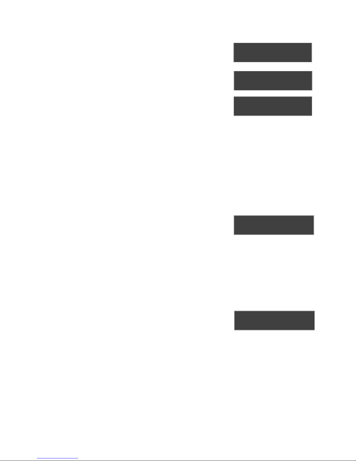
Sequencer AUX1 Step1…16: [1…127] sets AUX1 value in sequencer
track 3. (Soft Knob E3)
Sequencer AUX2 Steps1…16: [1…127] sets AUX2 value in sequencer
track 4. (Soft Knob E3)
Velocity Slew rate: [1…127] sets slew rate for velocity track. Slew
rate function works like a “lag processor” which limits the rate at
which a signal can increase or decrease in value. (Soft Knob E2)
AUX1 Slew rate: [1…127] sets slew rate for AUX1 track. (Soft Knob E3)
AUX2 Slew rate: [1…127] sets slew rate for AUX2 track. (Soft Knob E4)
How to build a sequence manually?
1. Press arp/seq [select] button and make sure “span” option is
set to “step”, wrap option is set to a number more than 1, and
trigger is set to Key-RST.
2. Press arp/seq [select] button again until the “step edit” page is
displayed:
3. Use [E1] knob to select the steps then enter/change notes with
[E3].
4. Press [preview] button or any key on your keyboard to hear
the arranged sequence.
How to record a sequence via MIDI?
1. Press arp/seq [select] button until the “step edit” page is
displayed, then press [Enter] button. The xeno will write PRESS
on the right corner of the screen, jump to the first step and the
seq LED blink:
2. Play notes on your external keyboard, the sequencer automatically jumps to the next step after you
play a note until it reaches the wrap point.
3. Press arp/seq [select] button to stop recording
4. Press [preview] button or any key on your keyboard to hear the arranged sequence.
18
Page 19
XENOPHONE Reference Manual - - - - - - - - - - - - - - - - - - - - - - - - - - - - - - - - - - - - - - - - - - - - - - - - HYPERSYNTH
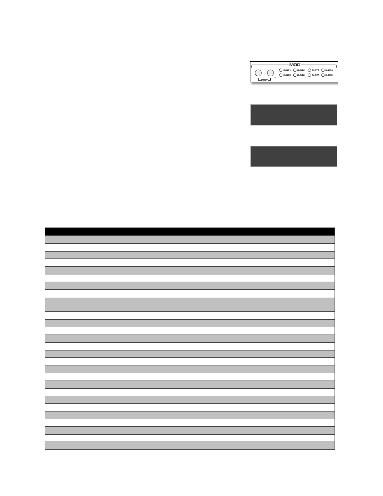
Source Name
Description
Signal Polarity
none
No source.
--
LFO1
Current value of the LFO1.
bipolar
LFO2
Current value of the LFO2.
bipolar
LFO3
Current value of the LFO3.
bipolar
Amp Env
Current value of the Amplitude envelope.
unipolar
Flt Env
Current value of the Filter envelope.
unipolar
Mod Env
Current value of the Mod envelope.
unipolar
keytrkU
MIDI Note number (0-127).
unipolar
keytrkB
MIDI Note number that uses C4 (MIDI note 60) as the center. Higher keys than the center key
transmit positive values, lower keys negative values.
bipolar
KeyFllw
It is like KeytrkB but it truly tracks the voice pitch including portamento and pitchbend signal.
bipolar
Velocit
MIDI Note-On velocity information.
unipolar
P-Wheel
MIDI Pitch wheel data.
bipolar
M-Wheel
MIDI modulation wheel data (CC#01) or [E1] knob on homepage.
unipolar
A-Touch
MIDI aftertouch/channel pressure data or [E2] knob on homepage.
unipolar
#Breath
MIDI Breath controller (CC#2).
unipolar
#Foot
MIDI Foot controller (CC#4).
unipolar
#Exp
MIDI Expression Pedal controller (CC#11).
unipolar
#Pedal
MIDI Sustain Pedal controller (CC#64).
unipolar
Rand-U
A random unipolar source.
unipolar
Rand-B
A random bipolar source.
bipolar
RandKey
A random bipolar value that will be generated after pressing a key.
bipolar
Altrnat
Sends a constant value of 1 after pressing the first key and -1 after pressing the second key.
bipolar
Constnt
Sends a constant value of 1. This can be useful for offsetting a certain parameter.
unipolar
CV-In
Current value of the CV in voltage. (CV connector must be configured as input in global menu)
bipolar
EXT-Lvl
Current level of external input signal. (An audio source must be connected to external input)
unipolar
LFO1*MW
LFO1 multiplied by Mod Wheel data. (Useful for creating variable depth vibrato)
bipolar
LFO2*MW
LFO2 multiplied by Mod Wheel data.
bipolar
Source1 Target1
Mod Env OSC1 Level
Source1 Depth=+26.5
Mod Env OSC1 Level
MODULATION MATRIX
Xenophone features 8 slots modulation matrix. Every slot has a
dedicated LED, which shows that the modulation is active or not. If
the depth is set to zero or “none” is selected as source or target, the
slot LED will turn off showing that there is no modulation on that
path. Using [+/-] buttons you can select the different slots.
Source 1…8: [] sets modulation source (see source table). (Soft Knob E1)
Target 1…8: [] sets modulation target (see target table). (Soft Knob E3)
Depth 1…8: [] sets modulation depth. (Coarse Soft Knob E2, Fine E4)
All sources, whether it is MIDI data or hardware modulator, are converted to the same range. The range
covers [0…+1] for unipolar and [-1…+1] for bipolar sources. Unipolar means that the source is only
increasing (or if applied with negative depth, decreasing) the target’s value. Bipolar means that the source
can increase or decrease the target's value.
Source Table
19
Page 20
XENOPHONE Reference Manual - - - - - - - - - - - - - - - - - - - - - - - - - - - - - - - - - - - - - - - - - - - - - - - - HYPERSYNTH
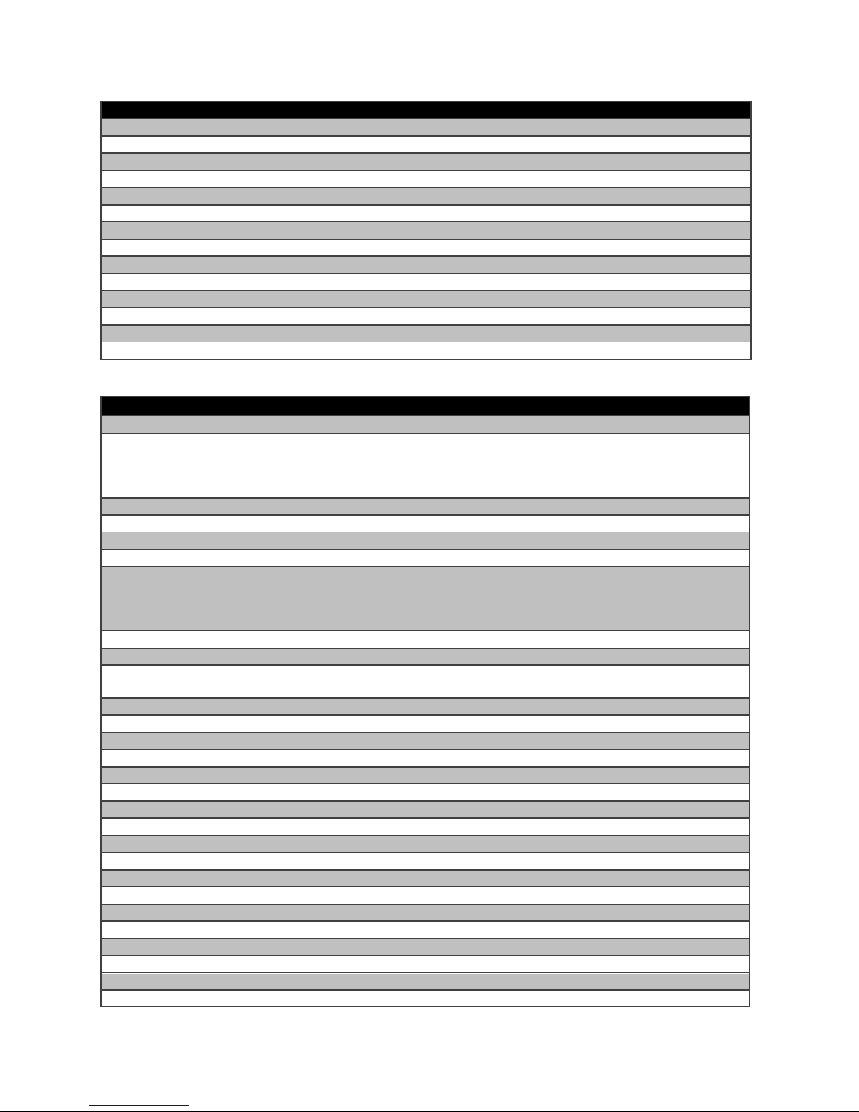
Source Name
Description
Signal Polarity
LFO3*MW
LFO3 multiplied by Mod Wheel data.
bipolar
LFO1*AT
LFO1 multiplied by Aftertouch data. (Useful for creating variable depth vibrato)
bipolar
LFO2*AT
LFO2 multiplied by Aftertouch data.
bipolar
LFO3*AT
LFO3 multiplied by Aftertouch data.
bipolar
LFO1*E3
LFO1 multiplied by Modulation Envelope (ENV3).
bipolar
LFO2*E3
LFO2 multiplied by Modulation Envelope (ENV3).
bipolar
LFO3*E3
LFO3 multiplied by Modulation Envelope (ENV3).
bipolar
LFO1*2
LFO1 multiplied by LFO2.
bipolar
LFO1*3
LFO1 multiplied by LFO3.
bipolar
SEQ-T1
Current value of sequencer track1 (note).
unipolar
SEQ-T2
Current value of sequencer track2 (velocity).
unipolar
SEQ-T3
Current value of sequencer track3 (AUX1).
unipolar
SEQ-T4
Current value of sequencer track4 (AUX2).
unipolar
ATouchP
MIDI Polyphonic aftertouch data.
unipolar
Target Name
Description
Target Name
Description
None
No source.
Master Bal
OSC1 Pitch
The tuning of oscillator 1 in semitones (+12…-
12). A mod depth value of +100% transposes the
oscillator one octave up, -100% transposes one
octave down.
DFX Wet
--
OSC2 Pitch
See OSC1 Pitch description
LFO1 Rate
--
OSC3 Pitch
See OSC1 Pitch description
LFO2 Rate
--
OSC1+2 Pitch
Oscillator 1 and 2 pitch
LFO3 Rate
--
Main Pitch
Oscillator 1, 2 and 3 pitch
LFO1 Depth
--
OSC1 PitchW
The tuning of oscillator 1 in octave (+10…-10). A
mod depth value of +100% transposes the
oscillator 10 octaves up, -100% transposes 10
octaves down. (Wide Pitch)
LFO3 Depth
--
OSC2 PitchW
See OSC1 PitchW description
Amp Env A
Amp Envelope Attack
OSC3 PitchW
See OSC1 PitchW description
Amp Env H
Amp Envelope Hold
OSC1+2
PtchW
Oscillator 1 and 2 wide pitch
Amp Env D
Amp Envelope Decay
Main PitchW
Oscillator 1, 2 and 3 wide pitch
Amp Env R
Amp Envelope Release
OSC1 Level
Oscillator 1 level
Flt Env A
Filter Envelope Attack
OSC2 Level
Oscillator 2 level
Flt Env H
Filter Envelope Hold
Sub1 Level
Sub Oscillator 1 level
Flt Env D
Filter Envelope Decay
Sub2 Level
Sub Oscillator 2 level
Flt Env R
Filter Envelope Release
OSC3/N Level
Oscillator 3 or Noise generator level
Mod Env A
Mod Envelope Attack
Ring Level
Ring Modulator level
Mod Env H
Mod Envelope Hold
EXT Level
External Input or Feedback level
Mod Env D
Mod Envelope Decay
OSC1 PW
Oscillator 1 Pulse Width
Mod Env R
Mod Envelope Release
OSC1 Shp
Oscillator 1 Shape
Matrix Dpth1
The depth of slot1
OSC2 PW
Oscillator 2 Pulse Width
Matrix Dpth2
The depth of slot2
OSC2 Shp
Oscillator 2 Shape
Matrix Dpth3
The depth of slot3
Fm Depth
--
Matrix Dpth4
The depth of slot4
Porta Time
--
DFX P0
--
Filter Freq
--
DFX P1
--
Flter Res
--
DFX P2
--
Flt Env Dpth
--
CV-OUT
CV output level
Master Level
--
Target Table
20
Page 21
XENOPHONE Reference Manual - - - - - - - - - - - - - - - - - - - - - - - - - - - - - - - - - - - - - - - - - - - - - - - - HYPERSYNTH
Function
Transmitted
Recognized
Remarks
Basic Channel
Default
Changed
1
1-16 1 1-16 User selectable
Mode
Default
Changed
MODE 3
X
MODE 4*
X
Note number
Sound range
0-127
0-127
Velocity
Note On
Note Off
O 0-127
X
O 1-127
X
Aftertouch
Keys
Channels
X
O* O O *[E2] Knob
Pitchbend
X O
Control Change
O O Program Change
Actual No.
O 0-127
O 0-127
Displayed 1-128
System Exclusive
O O
NRPNs
O O RPNs
X X
System
Common
Song Position
Song Select
Tune Request
X
X
X
X
X
X
System Real
Time
Clock
Commands
O X O X
Aux Messages
Local On/Off
All Notes Off
Act. Sensing
Reset
X
X
X
X
X
O
X
X
Parameter
CC
NRPN
Range
Description
OSC 1-Semitone
3 0-120
center=60
OSC 1-Cent
5 0-100
center=50
OSC 1-Keytrck
13 0-1
off=1, on=0
OSC 1-Waveform
9 0-7
OSC 1-PW
0 0-200
Duty cycle 50% = 100
OSC 1-Shape
1 0-200
OSC 1-Phase
10 0-127
OSC 1-Sub Type
12 0-4
OSC 2-Semitone
14 0-120
center=60
OSC 2-Cent
15 0-100
center=50
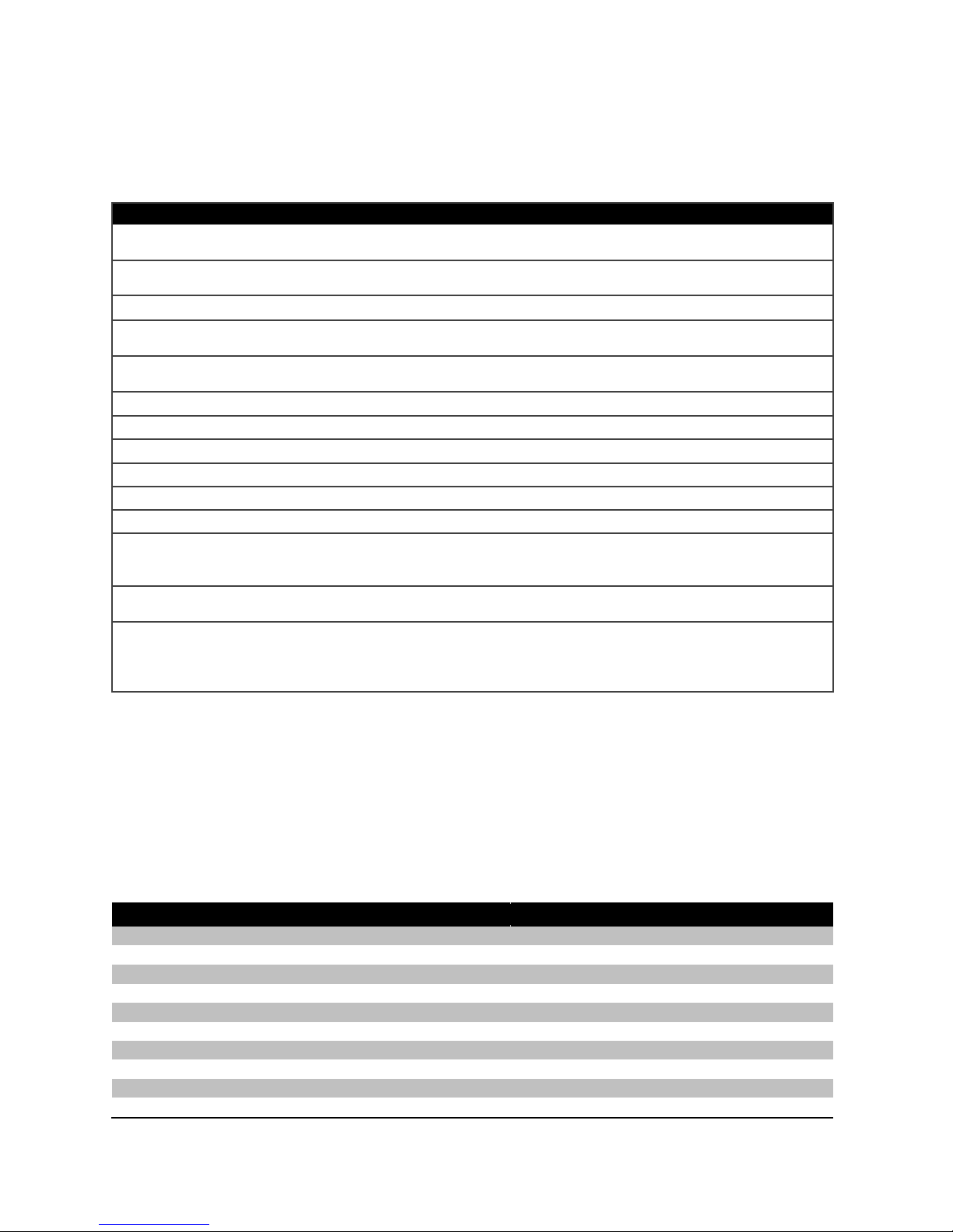
APPENDIX A
MIDI Implementation Chart
O = implemented Modes: Mode 1 - Omni On, Poly Mode 3 - Omni Off, Poly
X = not supported Mode 2 - Omni On, Mono Mode 4 - Omni Off, Mono
APPENDIX B
MIDI CC/NRPN Table
21
Page 22

XENOPHONE Reference Manual - - - - - - - - - - - - - - - - - - - - - - - - - - - - - - - - - - - - - - - - - - - - - - - - HYPERSYNTH
Parameter
CC
NRPN
Range
Description
OSC 2-Keytrck
19 0-1
off=1, on=0
OSC 2-Waveform
16 0-7
OSC 2-PW
3 0-200
Duty cycle 50% = 100
OSC 2-Shape
4 0-200
OSC 2-Phase
17 0-127
OSC 2-Sub Type
18 0-4
OSC 3-Semitone
20 0-120
center=60
OSC 3-Type
21 0-4
OSC 3-Keytrck
119 0-1
off=1, on=0
Mixer-OSC 1 Level
29 0-127
Mixer-OSC 1 Sub Level
30 0-127
Mixer-OSC 2 Level
31 0-127
Mixer-OSC 2 Sub Level
33 0-127
Mixer-OSC 3 Level
36 0-127
Mixer-Ring Level
34 0-127
Mixer-Feed/EXT Level
35 0-127
Voice-Porta Time
22 0-127
Voice-Porta Type
23 0-3
Voice-Bend Range
28 0-24
Voice-Detune
24 0-50
Voice-FM Depth
5 0-1022
Voice-Analog
26 0-127
Voice-Sync
25 0-1
off=0, on=1
Voice-Phase Mode
27 0-1
freerun=0, Phase Reset=1
Filter-Freq
6 0-4095
Filter-Resonance
37 0-100
Filter-Keytrk
10
0-200
Center=100 (key track : off)
Filter-Env Depth
9 0-1000
Filter-Type
39 0-5
Filter-Slope
40 0-2
12dB=0, 18dB=1, 24dB=2
Filter-FM
41 0-1
off=0, on=1
Amp Env-Attack
14
0-255
1mS…29.9S
Amp Env-Hold
17
0-255
1mS…29.9S
Amp Env-Decay
15
0-255
1mS…29.9S
Amp Env-Sustain
48 0-100
2mS…29.9S
Amp Env-Release
16
0-255
Loop=0, Hold=255
Amp Env-Velocity
51 0-127
Amp Env-Style
49 0-3
Amp Env-Trigger
50 0-3
Flt Env-Delay
18
0-255
1mS…29.9S
Flt Env-Attack
19
0-255
1mS…29.9S
Flt Env-Hold
22
0-255
1mS…29.9S
Flt Env-Decay
20
0-255
1mS…29.9S
Flt Env-Sustain
52 0-100
Flt Env-Release
21
0-255
Loop=0 (2mS…29.9S)
Flt Env-Style
53 0-3
Flt Env-Trigger
54 0-5
Mod Env-Delay
23
0-255
1mS…29.9S
Mod Env-Attack
24
0-255
1mS…29.9S
Mod Env-Hold
27
0-255
1mS…29.9S
Mod Env-Decay
25
0-255
1mS…29.9S
22
Page 23

XENOPHONE Reference Manual - - - - - - - - - - - - - - - - - - - - - - - - - - - - - - - - - - - - - - - - - - - - - - - - HYPERSYNTH
Parameter
CC
NRPN
Range
Description
Mod Env-Sustain
55 0-100
Mod Env-Release
26
0-255
Loop=0 (2mS…29.9S)
Mod Env-Style
56 0-3
Mod Env-Trigger
57 0-5
LFO1-Sync
59 0-1
off=0, on=1
LFO1-Rate
29
0-1000
0.00…99.9 Hz
LFO1-Rate_Synced
60 0-14
LFO1-Waveform
58 0-5
LFO1-Reset
61 0-2
LFO1-Target
62 0-8
LFO1-Depth
28
0-2000
LFO2-Sync
65 0-1
off=0, on=1
LFO2-Rate
30
0-1000
0.00…99.9 Hz
LFO2-Rate_Synced
66 0-14
LFO2-Waveform
63 0-5
LFO2-Reset
67 0-2
LFO3-Sync
70 0-1
off=0, on=1
LFO3-Rate
32
0-1000
0.00…99.9 Hz
LFO3-Rate_Synced
71 0-14
LFO3-Waveform
69 0-5
LFO3-Reset
72 0-2
LFO3-Target
73 0-6
LFO3-Depth
31
0-2000
MOD Matrix-Source1
75 0-40
MOD Matrix-Target1
75 0-54
MOD Matrix-Depth1
33
0-2000
MOD Matrix-Source2
76 0-40
MOD Matrix-Target2
77 0-54
MOD Matrix-Depth2
34
0-2000
MOD Matrix-Source3
78 0-40
MOD Matrix-Target3
79 0-54
MOD Matrix-Depth3
35
0-2000
MOD Matrix-Source4
80 0-40
MOD Matrix-Target4
81 0-54
MOD Matrix-Depth4
36
0-2000
MOD Matrix-Source5
82 0-40
MOD Matrix-Target5
83 0-54
MOD Matrix-Depth5
37
0-2000
MOD Matrix-Source6
84 0-40
MOD Matrix-Target6
85 0-54
MOD Matrix-Depth6
38
0-2000
MOD Matrix-Source7
86 0-40
MOD Matrix-Target7
87 0-54
MOD Matrix-Depth7
39
0-2000
MOD Matrix-Source8
88 0-40
MOD Matrix-Target8
89 0-54
MOD Matrix-Depth8
40
0-2000
Distortion Type
43 0-4
DFX-Type
42 0-7
DFX-Sync
45 0-1
off=0, on=1
DFX-P0
11
0-200
23
Page 24

XENOPHONE Reference Manual - - - - - - - - - - - - - - - - - - - - - - - - - - - - - - - - - - - - - - - - - - - - - - - - HYPERSYNTH
Parameter
CC
NRPN
Range
Description
DFX-P1
12
0-200
DFX-P2
13
0-200
DFX-P0_Synced
46 0-14
DFX-P1_Synced
47 0-14
DFX-Wet
44 0-127
Master-Balance
8 0-126
center=64
Master-Volume
7 0-127
ARP-Tempo
42
500-2500
50.0…250.0 bpm
ARP-Clock Divider
90 0-14
ARP-Gate
94 0-127
ARP-Span
91 0-4
ARP-Range
92 0-2
ARP-Latch
93 0-127
off=0..63, on=64…127
SEQ-Wrap
102 0-15
SEQ-Keytrk
103 0-1
off=0, on=1
SEQ-Trigger
104 0-3
SEQ-Velocity
105 0-1
step=0, key=1
SEQ-Vel Slew
106 0-127
SEQ-AUX1 Slew
107 0-127
SEQ-AUX2 Slew
108 0-127
SEQ-Note Step1
43
0-127
Rest=127
SEQ-Note Step2
44
0-127
Rest=127
SEQ-Note Step3
45
0-127
Rest=127
SEQ-Note Step4
46
0-127
Rest=127
SEQ-Note Step5
47
0-127
Rest=127
SEQ-Note Step6
48
0-127
Rest=127
SEQ-Note Step7
49
0-127
Rest=127
SEQ-Note Step8
50
0-127
Rest=127
SEQ-Note Step9
51
0-127
Rest=127
SEQ-Note Step10
52
0-127
Rest=127
SEQ-Note Step11
53
0-127
Rest=127
SEQ-Note Step12
54
0-127
Rest=127
SEQ-Note Step13
55
0-127
Rest=127
SEQ-Note Step14
56
0-127
Rest=127
SEQ-Note Step15
57
0-127
Rest=127
SEQ-Note Step16
58
0-127
Rest=127
SEQ-Velocity Step1
59
0-127
SEQ-Velocity Step2
60
0-127
SEQ-Velocity Step3
61
0-127
SEQ-Velocity Step4
62
0-127
SEQ-Velocity Step5
63
0-127
SEQ-Velocity Step6
64
0-127
SEQ-Velocity Step7
65
0-127
SEQ-Velocity Step8
66
0-127
SEQ-Velocity Step9
67
0-127
SEQ-Velocity Step10
68
0-127
SEQ-Velocity Step11
69
0-127
SEQ-Velocity Step12
70
0-127
SEQ-Velocity Step13
71
0-127
SEQ-Velocity Step14
72
0-127
SEQ-Velocity Step15
73
0-127
24
Page 25

XENOPHONE Reference Manual - - - - - - - - - - - - - - - - - - - - - - - - - - - - - - - - - - - - - - - - - - - - - - - - HYPERSYNTH
Parameter
CC
NRPN
Range
Description
SEQ-Velocity Step16
74
0-127
SEQ-AUX1 Step1
75
0-127
SEQ-AUX1 Step2
76
0-127
SEQ-AUX1 Step3
77
0-127
SEQ-AUX1 Step4
78
0-127
SEQ-AUX1 Step5
79
0-127
SEQ-AUX1 Step6
80
0-127
SEQ-AUX1 Step7
81
0-127
SEQ-AUX1 Step8
82
0-127
SEQ-AUX1 Step9
83
0-127
SEQ-AUX1 Step10
84
0-127
SEQ-AUX1 Step11
85
0-127
SEQ-AUX1 Step12
86
0-127
SEQ-AUX1 Step13
87
0-127
SEQ-AUX1 Step14
88
0-127
SEQ-AUX1 Step15
89
0-127
SEQ-AUX1 Step16
90
0-127
SEQ-AUX2 Step1
91
0-127
SEQ-AUX2 Step2
92
0-127
SEQ-AUX2 Step3
93
0-127
SEQ-AUX2 Step4
94
0-127
SEQ-AUX2 Step5
95
0-127
SEQ-AUX2 Step6
96
0-127
SEQ-AUX2 Step7
97
0-127
SEQ-AUX2 Step8
98
0-127
SEQ-AUX2 Step9
99
0-127
SEQ-AUX2 Step10
100
0-127
SEQ-AUX2 Step11
101
0-127
SEQ-AUX2 Step12
102
0-127
SEQ-AUX2 Step13
103
0-127
SEQ-AUX2 Step14
104
0-127
SEQ-AUX2 Step15
105
0-127
SEQ-AUX2 Step16
106
0-127
SEQ-HOLD Step1
107
0-1
off=0, on=1
SEQ-HOLD Step2
108
0-1
off=0, on=1
SEQ-HOLD Step3
109
0-1
off=0, on=1
SEQ-HOLD Step4
110
0-1
off=0, on=1
SEQ-HOLD Step5
111
0-1
off=0, on=1
SEQ-HOLD Step6
112
0-1
off=0, on=1
SEQ-HOLD Step7
113
0-1
off=0, on=1
SEQ-HOLD Step8
114
0-1
off=0, on=1
SEQ-HOLD Step9
115
0-1
off=0, on=1
SEQ-HOLD Step10
116
0-1
off=0, on=1
SEQ-HOLD Step11
117
0-1
off=0, on=1
SEQ-HOLD Step12
118
0-1
off=0, on=1
SEQ-HOLD Step13
119
0-1
off=0, on=1
SEQ-HOLD Step14
120
0-1
off=0, on=1
SEQ-HOLD Step15
121
0-1
off=0, on=1
SEQ-HOLD Step16
122
0-1
off=0, on=1
25
Page 26

XENOPHONE Reference Manual - - - - - - - - - - - - - - - - - - - - - - - - - - - - - - - - - - - - - - - - - - - - - - - - HYPERSYNTH
APPENDIX C
Specifications
TYPE: Programmable Subtractive Analog Synthesizer
POLYPHONY: Monophonic
PROGRAM MEMORY: 896 Preset Programs, 7 banks, 128 Patches per bank
SOUND ENGINE: 3 oscillators, 1 multi-mode filter, 1 analog ring modulator, 3 envelope generators, 3 LFOs, Arpeggiator, 4x16
Sequencer and modulation matrix.
EFFECTS: Analog distortion, 24-bit Stereo Digital FX
FILTER FREQUENCY RESPONSE: 20-22K Hz
AUDIO OUTPUTS: 2x 1/4" TRS jacks (Impedance Balanced), Stereo L/R
MAXIMUM OUTPUT LEVEL: +17dBV (6.17 VRMS)
OUTPUT IMPEDANCE: 100 Ohm
AUDIO INPUT: 1x 1/4" TRS jack (Unbalanced)
MAXIMUM INPUT LEVEL: -5.5dBV (0.53 VRMS)
INPUT IMPEDANCE: 75k Ohm
HEADPHONE OUT: 1x 1/4" TRS stereo jack
CV/GATE INPUT/OUTPUT: 1x 1/4" TRS jack
CV/GATE OUT RANGE: CV=0…+10v DC, Gate=0/5v DC
CV/GATE IN RANGE: CV=-5…+5v DC, Gate=0…12v DC
MIDI CONNECTIONS: MIDI In, MIDI Out
USB PORT: 1x Type B
OPERATING SYSTEM: Flash Upgradeable Via USB
REAL-TIME CONTROLLERS: 26 endless encoders, 27 Buttons
POWER CONSUMPTION: 10 Watts max (12v DC)
DIMENSIONS (WXHXD): 12.9" L x 1.9" W x 6.5" H (32.8 cm x 5 cm x 16.7 cm)
WEIGHT: 2.8 lb (1.3 kg)
Specifications are subject to change without notice.
If you encounter any problems, or you have suggestions for future revisions, don’t hesitate to contact our technical
support at: [email protected]
Copyright © 2008-2015 HyperSynth
www.HyperSynth.com
26
 Loading...