

Page 1
Hypersen Technologies Co., Ltd. HPS-LC010
September 2018 Rev.1.1 1/70
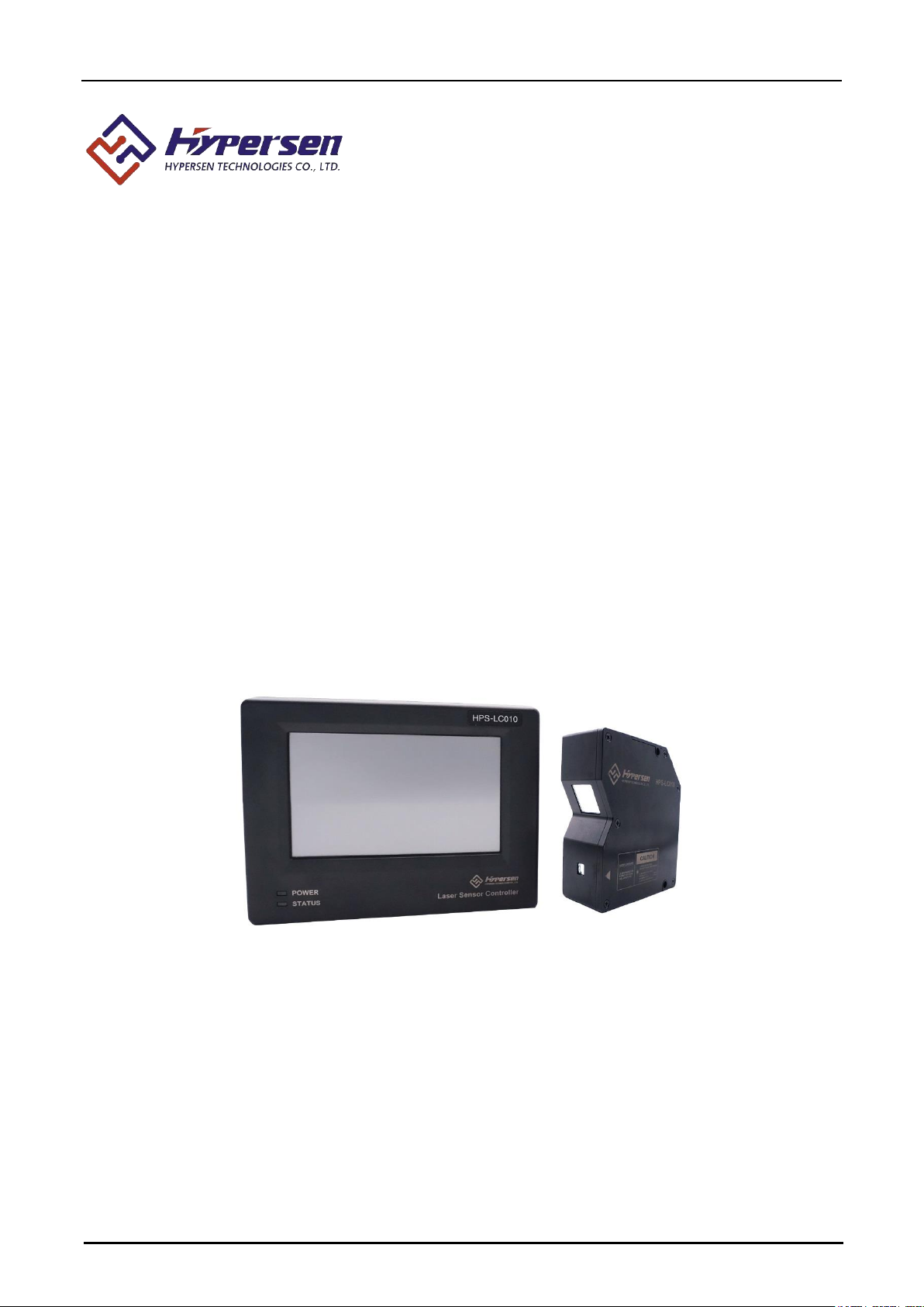
HPS-LC010
High-Accuracy Laser Displacement Sensor
User’s Manual
Page 2

Hypersen Technologies Co., Ltd. HPS-LC010
September 2018 Rev.1.1 2/70
Introduction
This manual describes the basic operations and hardware functions of the HPS-LC010 laser displacement
sensor. Before using the sensor, read this manual carefully to ensure complete understanding so that you can
take full advantage of this product’s performance and functions. Please deliver this manual to the end users of
this product.
Safety Preautions
General Precautions
• At startup and during operation, be sure to monitor the functions and performance of the HPS-LC010.
• It is recommanded that you take substantial safety measures to avoid any damage in case of product failure
• Do not modify it or use it in any way other than as described in the specifications. The warranty will be voided
in such cases.
• When it is used in combination with other devices, functions and performance may be degraded depending on
the operating conditions and surrounding environment.
• Do not use this product for the purpose to protect a human body or part of a human body.
• This product is not intended for use as an explosion-proof product. Do not use this product in a hazardous
location or potentially explosive atmosphere.
• Do not allow the temperature to change sharply around the HPS-LC010, including the accessories. Otherwise,
condensation may lead to a malfunction.
Warning
Ensuring safe operation
• Use the proper power supply voltage as specified. Failure to do so may cause a fire, electric shock, or
malfunction.
• Do not attempt to disassemble or modify the unit. Doing so may cause a fire, electric shock or unit malfunction.
Handling abnormal conditions
Turn off the power immediately in the following cases. Using in an abnormal condition could cause product
breakdown.
• If liquid or foreign matter enters the unit.
• If the unit is dropped or the housing is damaged.
• If smoke or an abnormal odor is emitted from the controller.
Caution
Ensuring safe operation
• Be sure to turn off the power to the HPS-LC010 and connected devices when you connect/disconnect the cable
to/from them. Failure to do so may result in product damage.
• Do not turn off the power while any item is being set. Part or all of the settings may be lost.
• Do not block the vent holes on the unit. The rise in the internal temperature may cause product failure.
Page 3

Hypersen Technologies Co., Ltd. HPS-LC010
September 2018 Rev.1.1 3/70
Installation environment
To use the HPS-LC010 properly and safely, avoid installing it in the following locations. Doing so may lead to
product breakdown.
• Location that is humid, dusty or poorly ventilated
• Location where the temperature becomes high, such as a place exposed to direct sunlight
• Location where there are flammable or corrosive gases
• Location where the product may be directly subjected to vibration or impact
• Location where water, oil or chemicals may splash onto the product
• Location where static electricity is readily generated
Noise control
When the product is installed near a noise source such as a power source or high-voltage lines, noise may cause
a malfunction or failure of the unit. Take corrective actions against noise by using noise filters, laying cables in a
separate conduit, and/or providing insulation when installing the controller and sensor head.
Influence of ambient temperature
Changes in the ambient temperature may cause the measurement to fluctuate. Be sure to keep the temperature
constant at all times. When the ambient temperature changes by 10°C, it takes about 60 minutes until the
temperature inside the unit is uniformly distributed.
Ambient light
Do not use the product near a lighting system that repeatedly turns on and off rapidly. If it is unavoidable to use
the unit in such a place, install a light shielding board or a similar object so that the light will not affect the
measurement.
Warming up
After turning on the power, wait approximately 30 minutes before using. Since the circuit is not stable immediately
after the power is turned on, the measured value may gradually change during this period.
Influence of dust or dirt
The measurement may be incorrect when dirt, dust or fluid such as water or oil interferes with measurement in
the following ways.
• Adhesion on the protective glass: Blow the dirt off with clean air. If dirt persists, wipe the glass surface gently
using a soft cloth moistened with alcohol.
• Adhesion on the surface of the measurement target: Blow the dirt off with clean air or wipe it off.
• Intrusion of floating dust or splash of fluid into the light-axis range: Take corrective action such as installing a
protective cover or air purge.
Other considerations
Influence of vibration
When the measurement target is vibrating, the measured value may fluctuate. In this case, increase the number
of averaging measurements to ensure more accurate measurement.
Page 4
Hypersen Technologies Co., Ltd. HPS-LC010
September 2018 Rev.1.1 4/70
Measurement target
The measured value may be incorrect if the shape or surface condition of the target varies with individual targets.
In this case, measure a known target and use the calibration function to correct the error.
Handling
Do not wipe the unit with a wet cloth, benzene, or thinner. This may cause discoloration or deformation of the
housing. If the unit becomes dirty, wipe it off with a cloth moistened with a mild detergent and then wipe with a
soft dry cloth.
Effect of atmospheric motions
Slow atmospheric motions may affect the measurement and result in fluctuation of the measured value. In such
a case, enclose the sensor head in an appropriate enclosure.
Precautions on CE Marking
The product conforms to the CE Marking under the conditions that the following requirements are satisfied. In
order to use the product be sure that the following requirements have already been satisfied beforehand. The
applicable standards (EMC Directive) are listed below:
EMI: EN61326-1, Class A
EMS: EN61326-1
Limit the length of the power supply cable and all input/output cables that are connected to the terminal panel of
the controller to 10 m or less. For those USB cables that are connected to the terminal panel of the controller,
winding two rounds of cable around a ferrite core at the distance of 100mm or closer to the USB interface of the
controller
Precautions on wiring
See Chapter 3 I/O terminals
Safety precautions on laser products
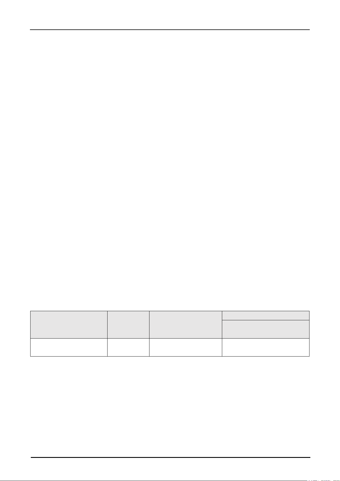
Reference distance and
measurement range
Resolution
Beam diameter
Type
Compliance with JIS/IEC
standards
When diffuse reflection,
55±10mm
0.1um
Approximately Φ30um
(reference distance)
HL-C205BE
Precautions on class III laser products
MPE (maximum permissible exposure): 2.5 mW/cm2
Follow the instructions mentioned in this manual. Otherwise, injury to the human body (eyes and skin) may result.
• Do not directly look at or touch the laser beam and its reflection from a mirror-like surface.
• Do not direct the beam at other people or into areas where other people unconnected with the laser work might
be present.
• Prevent the diffusion of the laser beam. Make the laser path as short as possible and be sure to terminate it
with a diffusion reflector or diffusion absorber which has proper reflectance and thermal characteristic. (It is
recommanded that you install a protective enclosure.)
Page 5
Hypersen Technologies Co., Ltd. HPS-LC010
September 2018 Rev.1.1 5/70
• Install the laser product carefully so that the laser beam is not unintentionally directed at mirror-like surfaces.
• Wear protective eye goggles appropriate for the laser beam wavelength.
• Do not disassemble this product. Laser emission from this product is not automatically stopped when it is
disassembled.
• Clean the aperture regulary. In addition, stop the emission of the laser beam when cleaning.
• Use an interlock function to block laser radiation in an emergency.
• Prevent prohibited laser radiation use by providing a button-operated switch or other control on the control
panel.
• Install the products so that the path of the laser beam is not as the same height as that of human eye.
Safety features of the laser product
Precautions on class I II or 3R laser products
After the controller is power on, the sensor head does not emit laser by default. Only when the LaserON button
at the top of the screen is pressed, the sensor head will emit laser light. At the same time, the input port of the
controller can be configured to control the laser emission of the sensor head through an external signal.
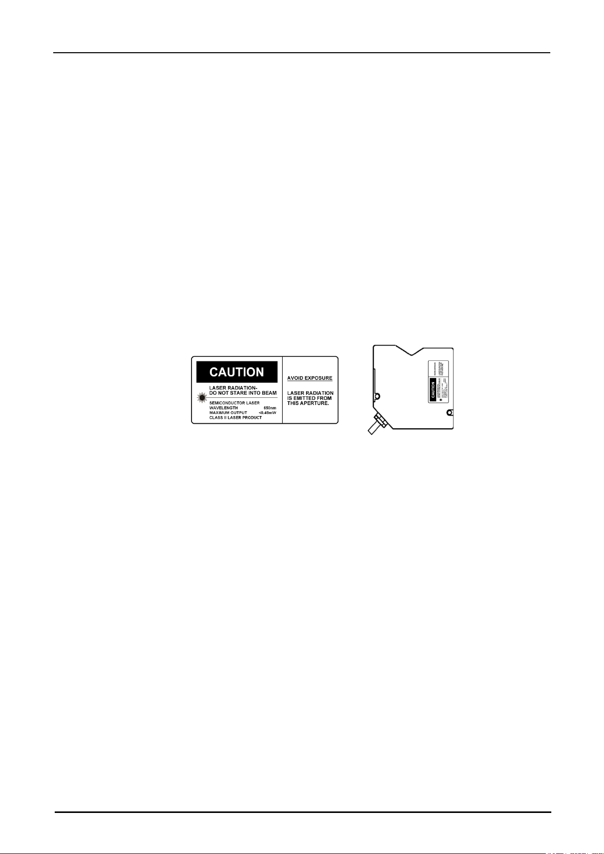
Warning label description and location
Label description location
Page 6

Hypersen Technologies Co., Ltd. HPS-LC010
September 2018 Rev.1.1 6/70
Content
Introduction ......................................................................................................................................................... 2
Safety Preautions ............................................................................................................................................... 2
General Precautions ................................................................................................................................. 2
Warning ...................................................................................................................................................... 2
Caution ....................................................................................................................................................... 2
Other considerations ................................................................................................................................ 3
Precautions on CE Marking ..................................................................................................................... 4
Precautions on wiring ............................................................................................................................... 4
Safety precautions on laser products ..................................................................................................... 4
Chapter 1 Before use ................................................................................................................................................ 9
System Configuration ........................................................................................................................................ 9
Checking the Package Contents ...................................................................................................................10
Part Names and Functions .............................................................................................................................11
Controller .................................................................................................................................................. 11
Sensor head ............................................................................................................................................. 12
Mounting / Connecting Device .......................................................................................................................12
Mounting the sensor head ..................................................................................................................... 12
Mounting the sensor head according to the measurement target ................................................... 13
Mounting the controller ........................................................................................................................... 13
Mounting the sensor head ..................................................................................................................... 14
Controller main interface ........................................................................................................................ 14
Chapter 2 Operations during Measurement ........................................................................................................16
Set tolerance comparator value .....................................................................................................................16
Auto-Zero ..........................................................................................................................................................17
Set specified value as zero point ...................................................................................................................17
Program Function.............................................................................................................................................17
Switch Program Number .................................................................................................................................18
Set Sensor Head ..............................................................................................................................................18
Set measurement parameters .......................................................................................................................18
Use filters to stabilize the measurement.............................................................................................. 18
Set the median filter ................................................................................................................................ 18
Set the average filter .............................................................................................................................. 19
Set measurement mode ......................................................................................................................... 19
Data storage function ......................................................................................................................................24
Set data storage ...................................................................................................................................... 25
Set Operation Environment ............................................................................................................................25
Function list and initial value ................................................................................................................. 25
Set screen backlight brightness ............................................................................................................ 25
Set the backlight maintenance time ..................................................................................................... 25
Set touch screen auto-lock time ........................................................................................................... 26
Set warning output .................................................................................................................................. 26
Recalibrate the touch screen................................................................................................................. 26
Page 7

Hypersen Technologies Co., Ltd. HPS-LC010
September 2018 Rev.1.1 7/70
Set communication method ................................................................................................................... 26
Chapter 3 I/O Terminals ..........................................................................................................................................28
Names and Functions of the I/O Terminals ..................................................................................................28
12-pin terminal block (Terminals) .......................................................................................................... 28
Power Terminal ........................................................................................................................................ 30
Function of the I/O signal ....................................................................................................................... 30
Input terminal configuration ............................................................................................................................30
Configuration for Auto-Zero ................................................................................................................... 31
Configuration for Cancel Auto-Zero function ....................................................................................... 31
Configuration for Clock Synchronization function .............................................................................. 32
Configuration for Laser Control function .............................................................................................. 32
Output Terminal Configuration .......................................................................................................................33
Configuration for GO output .................................................................................................................. 33
Configuration for HI output..................................................................................................................... 33
Configuration for LO output ................................................................................................................... 34
Configuration for ALARM output ........................................................................................................... 34
Chapter 4 Firmware upgrade .................................................................................................................................34
Chapter 5 Communication Command ..................................................................................................................35
Command and returned data format .............................................................................................................35
Commands ........................................................................................................................................................36
Command #1 Read Controller Version Information ........................................................................... 36
Command #2 Read DSP Algorithm Version Information .................................................................. 36
Command #3 Read Sensor Head Version Information ..................................................................... 37
Command #4 Set Zero-Offset Value .................................................................................................... 37
Command #5 Auto-Zero or Cancel Auto-Zero .................................................................................... 38
Command #6 Read Current Zero-Offset Value .................................................................................. 39
Command #7 Single Measurement ...................................................................................................... 39
Command #8 Continuous Measurement ............................................................................................. 40
Command #9 Program Setting ............................................................................................................. 41
Command #10 Set or Read Current Program Number ..................................................................... 42
Command #11 Set or Read Laser Status ............................................................................................ 43
Command #12 Set or read measurement mode ................................................................................ 44
Command #13 Set or Read Data Storage Parameters..................................................................... 45
Command #14 Start or Stop Data Storage ......................................................................................... 46
Command #15 Read Saved Data ......................................................................................................... 47
Command #16 Read Stored Data ........................................................................................................ 48
Command #17 Set or Read Input Port Configuration ........................................................................ 49
Command #18 Set or Read Output Port Configuration .................................................................... 50
Command #19 Set or Read Filter Parameters ................................................................................... 51
Command #20 Set or Read Controller Sampling Times ................................................................... 52
Command#21 Set or read alarm source ............................................................................................. 53
Command #22 Set or Read Backlight Brightness Value ................................................................... 54
Command #23 Set or Read Backlight Timeout .................................................................................. 55
Command #24 Set or Read Screen Lock Time .................................................................................. 56
Page 8

Hypersen Technologies Co., Ltd. HPS-LC010
September 2018 Rev.1.1 8/70
CRC16 C language implementation ..................................................................................................... 58
Chapter 6 Specification ...........................................................................................................................................63
Specification ......................................................................................................................................................63
Controller .................................................................................................................................................. 63
Sensor head ............................................................................................................................................. 64
Dimension .........................................................................................................................................................65
HPS-LC010 controller ............................................................................................................................ 65
HPS-LC010 sensor head ....................................................................................................................... 65
Appendix ...................................................................................................................................................................67
Troubleshooting ................................................................................................................................................67
Option list ..........................................................................................................................................................69
Revision history ................................................................................................................................................69
Product warranty policy ...........................................................................................................................................70
Page 9
Hypersen Technologies Co., Ltd. HPS-LC010
September 2018 Rev.1.1 9/70
Chapter 1 Before use
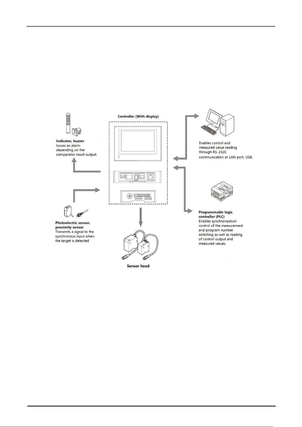
System Configuration
Page 10
Hypersen Technologies Co., Ltd. HPS-LC010
September 2018 Rev.1.1 10/70
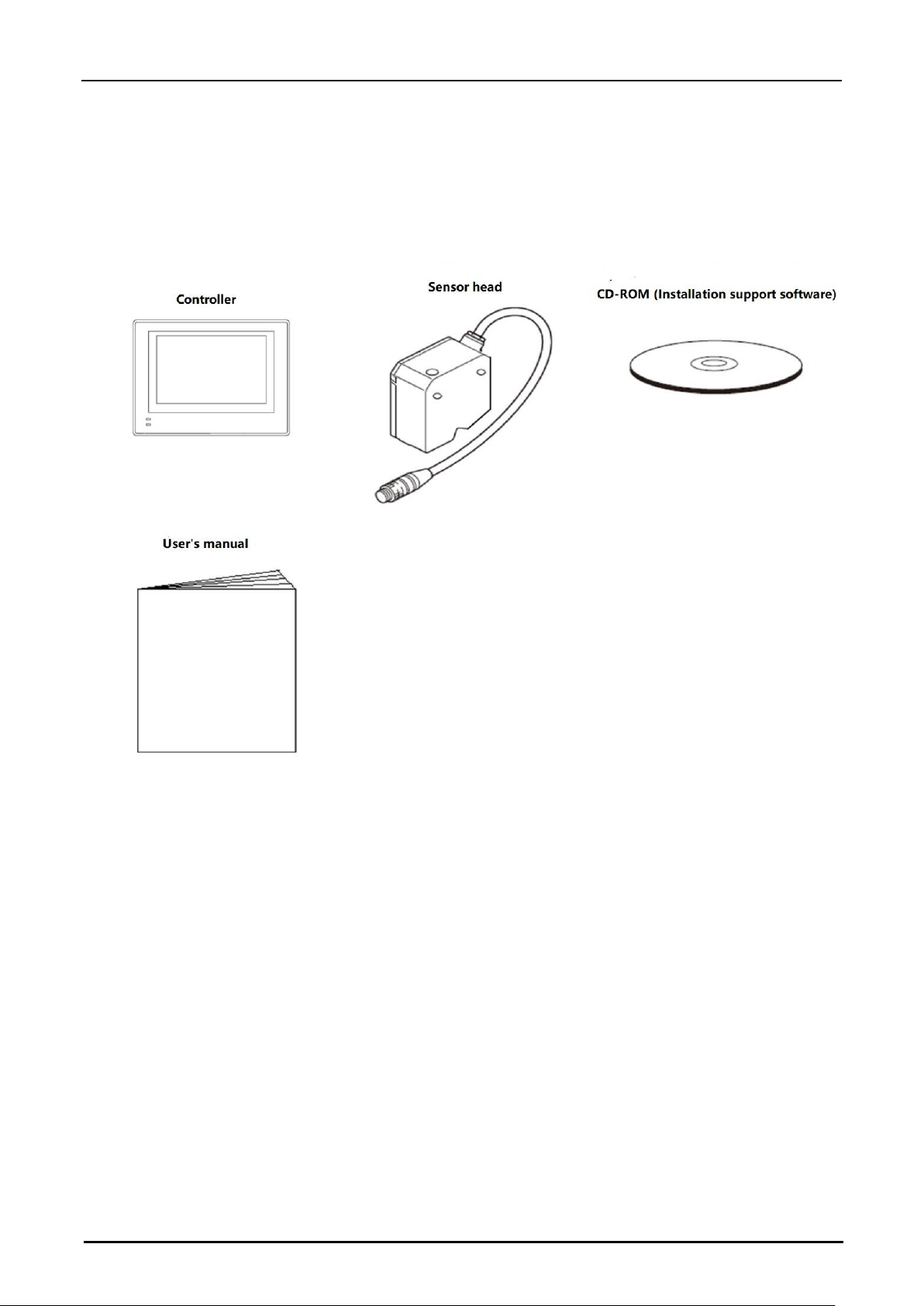
Checking the Package Contents
Ensure that all the components and accessories listed below are included in the package of the model you
purchased before using the unit.
Page 11
Hypersen Technologies Co., Ltd. HPS-LC010
September 2018 Rev.1.1 11/70
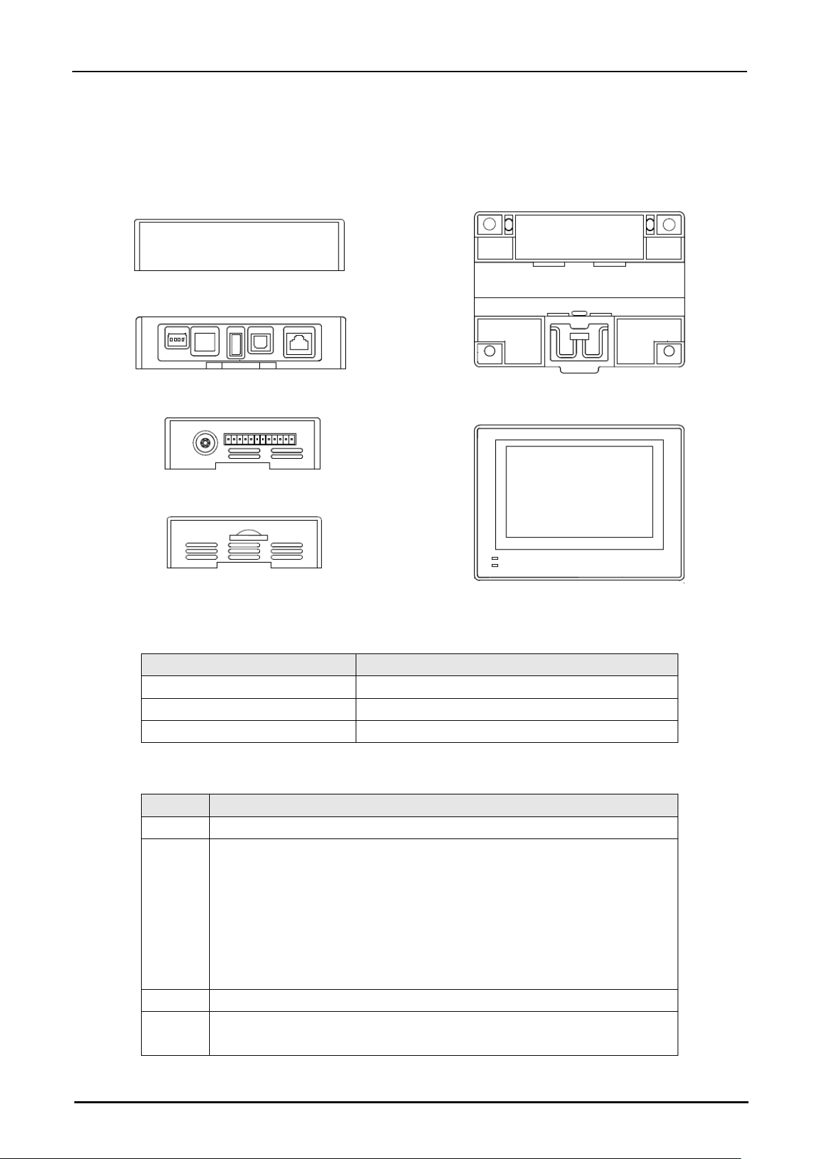
Part Names and Functions
Controller
The items displayed on the detection value display and their meanings
Display
Meaning
99.9999
Exceed maximum range
-99.9999
Exceed minimum range
88.8888
Insufficient light signal received
Operation button
Button
Function
PRO
• Press this button for 3 seconds during a test to change the program group.
SET
• Press this button to enter the tolerance setting mode. First press enters
maximum tolerance setting mode.
• Second press enter minimum tolerance setting mode.
• Third press quit tolerance setting mode, previous setting value will not be
saved.
• In setting, continuously press button could cancel setting and back to
measuring screen.
ENT
• In setting, press this button to save the setting value
ZERO
• Press this button to set the measurement value to zero, press this button
for 3 seconds to return the ABS measurement mode.
Page 12
Hypersen Technologies Co., Ltd. HPS-LC010
September 2018 Rev.1.1 12/70
Sensor head
(1) Laser emission LED,
lights or flashes while the product is in operation.
(2) Mounting holes
(3) Connecting cable, connected to the head-to-controller cable.
(4) Transmitter emits the laser beam, receiver receives the laser beam for measurement. Two parts work
simultaneously for measurement this part is protected with a glass cover.
(5) Working status of indicator:
Target is at the center of the measurement range
Green light on
Target is within the measurement range
Green light flash
Target is outside the measurement range.
Red light flash
Mounting / Connecting Device
Mounting the sensor head
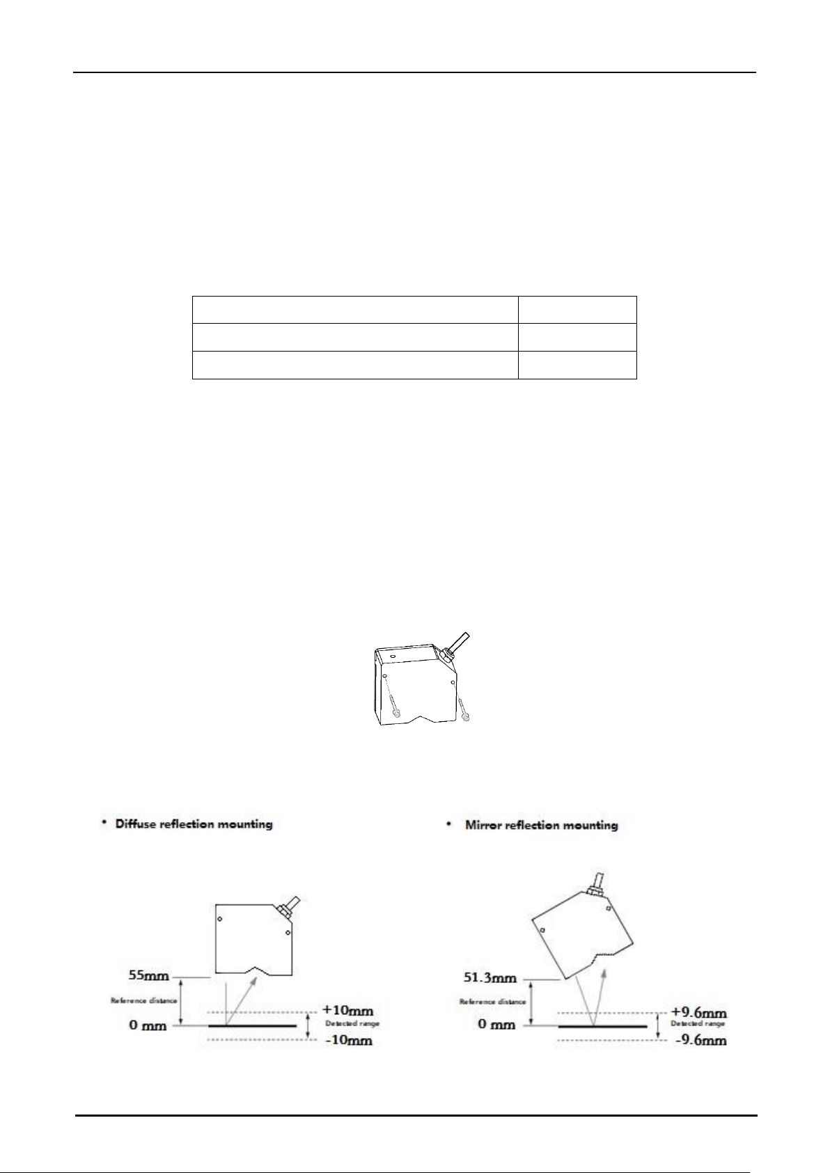
Determine the distance between the sensor head and the measurement target, and secure the head using
screws through the two mounting holes. When the sensor head is mounted onto a plastic object, limit the ambient
temperature to 45°C or lower. It is recommanded that you provide insulation when the product is used in a
positive ground environment.
HPS-LC010 mounting method
HPS-LC010 measurement range
Page 13
Hypersen Technologies Co., Ltd. HPS-LC010
September 2018 Rev.1.1 13/70
For both diffuse-reflection mounting and mirror-reflection mounting, the laser emission LED lights in green when
the target is within approximately ±2.0 mm of the reference position, the laser emission LED lights in green flash
when the target is in other positions within the reference position. The laser emission LED lights in red flash
when the target is out of the reference position. The sensor head’s reference tilt is 15° in mirror reflection
mounting, the real displacement is △d = △L*cos(15°),△
L is measured value.
Mounting the sensor head according to the measurement target
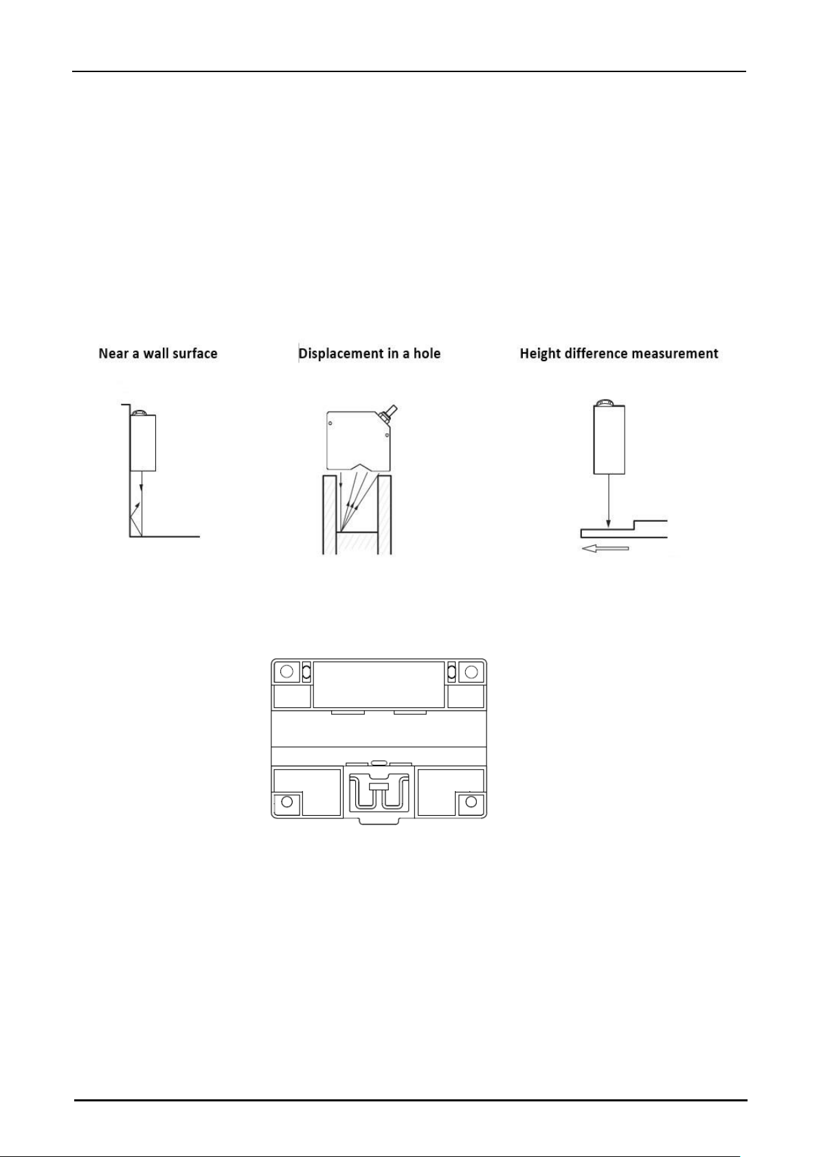
Measurement distance
Sensor head is most stable detecting when as close to the reference distance.
It is recommanded to mount the sensor head in the orientations indicated in the figures below.
Mounting the controller
Mount the controller to the DIN rail or secure it with screws.
To secure the controller with the screws on the bottom
Provide clearance of 50 mm or more above, 30 mm or more on each side, and 30 mm or more at the rear of the
controller for ventilation. In addition, for ensuring the safety of the cable connection work, leave 65 mm or more
space in front of the terminal panel of the controller.
To mount the controller to the DIN rail
Provide clearance of 30 mm or more between the controllers, 50 mm or more above and 30 mm or more below
the controller.
Page 14
Hypersen Technologies Co., Ltd. HPS-LC010
September 2018 Rev.1.1 14/70
CAUTION
Do not block the ventilation holes on the top and bottom of the controller. The heat may stay inside and cause a
malfunction. When the temperature inside the control panel exceeds the specified ambient temperature,
decrease the temperature of the controller bottom to the specified ambient temperature or lower by using forced
air cooling or by providing more clearance around the controller.
Mounting the sensor head
Connect the connector of the sensor head cable to the sensor head connector on the controller. A Press sounds
to indicate that the connector has been inserted. When disconnect the cable, press the pressure plug in the
direction of the cable and pull out the connector.
Connecting Power
1. Remove the terminal block from the controller and loosen the screw with a screwdriver.
2. Connect the 24 VDC power supply to the 11th and 12th terminals of the terminal block. The 11th terminal is
connected to the positive terminal of the power supply, and the 12th terminal is connected to the negative terminal
of the power supply. It is also recommanded to connect the 10th terminal (protective terminal) of the terminal
block to the chassis ground.
3. Gently pull each lead to ensure it is properly seated.
4. Put the terminal block back on the controller.
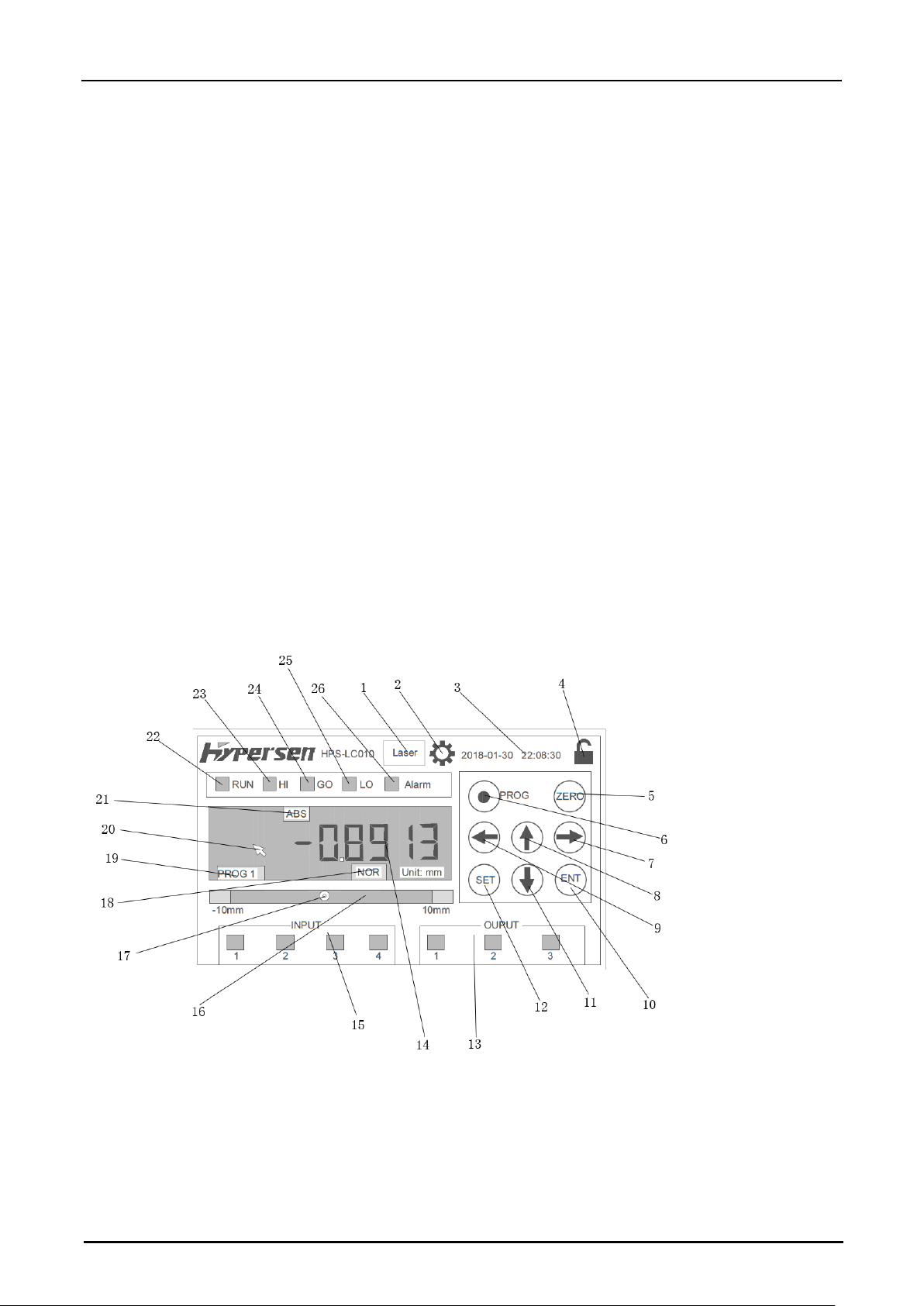
Controller main interface
1: Laser control and status button
Green: Laser On
Red: Laser Off
2: Set menu button
Page 15

Hypersen Technologies Co., Ltd. HPS-LC010
September 2018 Rev.1.1 15/70
3: System time
4: Screen lock button
Press this button can lock or unlock the touch screen.
5: Automatic zeroing button
Shorly press can automatically zeroing, press it for 3 seconds can cancel automatically zeroing, return to
absolute displacement mode (screen displays ABS icon).
6: Program group switch button
Press this button for 3 seconds can switch program group.
7: Right arrow
In setting mode, used to move the editing position to the right.
8: Up arrow
In setting mode, editing value will increase 1 by a single press.
9: Left arrow
In setting mode, used to move the editing position to the left.
10: Confirm button
Used to save setting values in setting mode.
11: Down arrow
In setting mode, editing value will decrease 1 by a single press.
12: Tolerance setting button
Edit the tolerance set value of the current program group. 1st press set the edit upper tolerance value, 2nd press
set the edit tolerance lower tolerance value, and 3rd press quit the edit mode (the setting values will not be
saved).
13: Output port status
14: Current measured value
15: Input port status
16: CMOS photosensitive area indication
17: The physical position of the laser spot on the CMOS sensor
18: Current measurement mode
19: Current program group number
20: Touch screen pointer
21: Automatic zeroing / ABS indicator
No display in automatic zero
ing mod
e and shows “ABS” in abosolutely displacement mode.
22: Operation status indication
23: Exceeds the tolerance upper limit indication, when the measured value is greater than the tolerance upper
limit, indicates red
24: Within tolerance range indication, when the measured value is within tolerance range, indicates green
25: Exceeds the tolerance lower limit indication, when the measured value is greater than the tolerance lower
limit, indicates red
26: Warning indication, when a warning signal is generated, indicates red
Page 16
Hypersen Technologies Co., Ltd. HPS-LC010
September 2018 Rev.1.1 16/70
Chapter 2 Operations during Measurement
Set tolerance comparator value
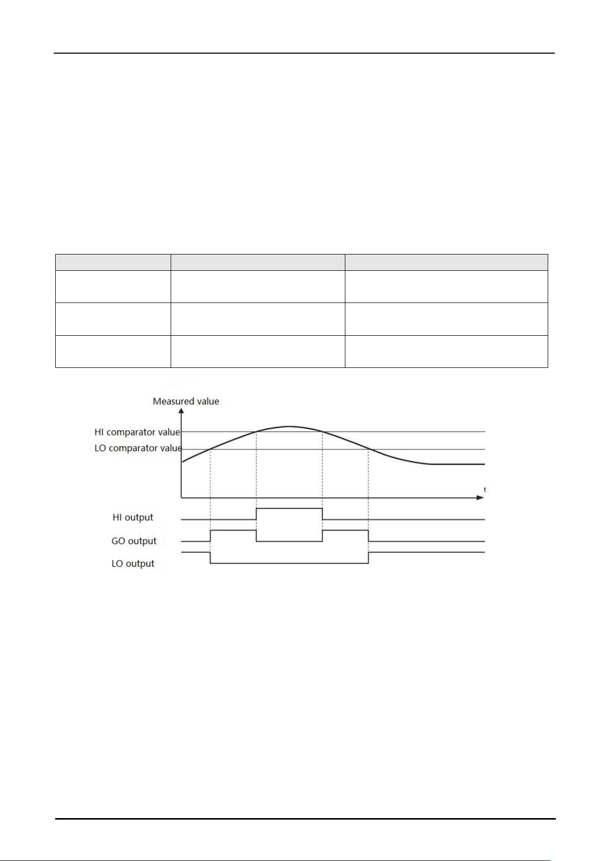
The function of the tolerance comparator setting
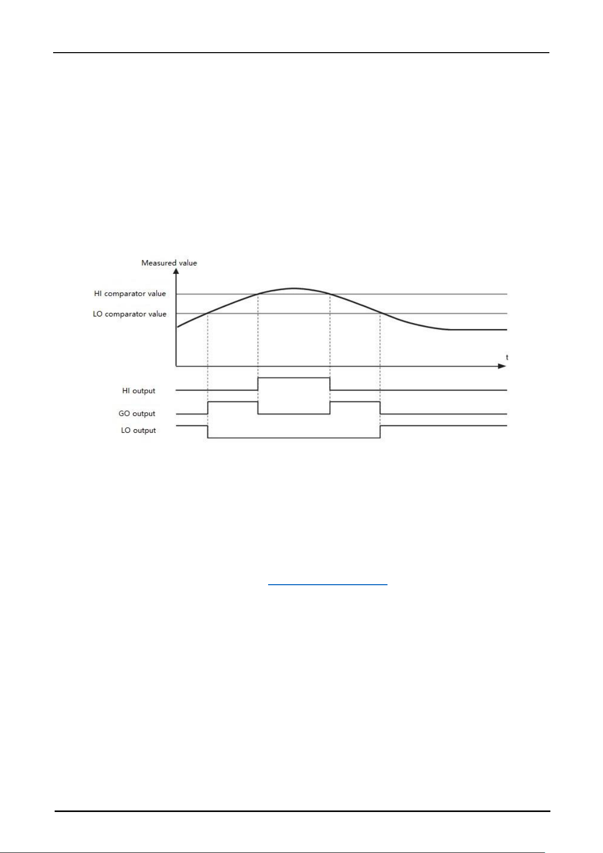
You can set tolerance values (tolerance comparator values) used to decide whether the measured value is within
the allowable range. The measured values are classified into three levels based on the tolerance: HI when the
value exceeds the upper limit, LO when the value is below the lower limit, and GO when the value is within the
allowable range.
Comparator status
Range
Display
HI
HI comparator value < Measured
value
The "HI" LED lights and is indicated in red.
GO
LO comparator value < Measured
value < HI comparator value
The "GO" LED lights and is indicated in
green.
LO
Measured value < LO comparator
value
The "LO" LED lights and is indicated in red.
Note:
1
.
Need to set the OUT output port to enable this function.
2
.
The output polarity of the OUT port can be set by sending command (command #18) or on the controller operation interface.
Set the tolerance through controller operation interface (tolerance comparator value)
1. Press the SET button. The system enters the tolerance HI comparator setting mode.
2. Press the up and down arrows to edit the value. Press the left and right arrows to move the editing position
left and right. A red arrow will flash above the currently edited position.
3. Press the SET button. The system enters the tolerance LO comparator setting mode.
4. Set LO compatator value, the method is same as step 2
5. Press ENT to save the current tolerance setting and return to the measurement mode. Press the SET button
again cancels this setting and returns to measurement mode.
Page 17
Hypersen Technologies Co., Ltd. HPS-LC010
September 2018 Rev.1.1 17/70
Auto-Zero
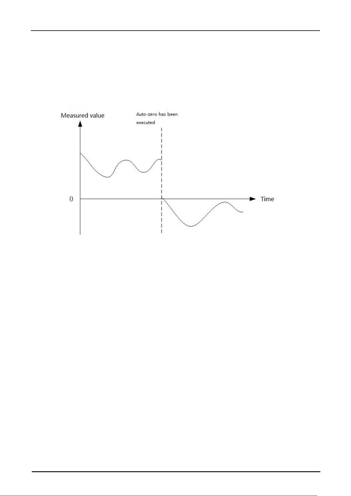
The auto-zero function can be used to set a reference point at "0", for example, when the target is changed. You
can instantaneously reset the currently displayed value to "0" by pressing the [ZERO] button or other operation.
Set the auto-zero from the display panel
1. Align the sensor head with the detection target and adjust the position of the sensor head so that the laser
spot is within the measurement range.
2. Press the ZERO button. The measured value display shows zero.
• Press ZERO button for 3 seconds will cancel AUTO-ZERO setting, return to abosolute displacement mode.
Automatic zeroing through I/O terminal input: When any one of the input terminals is configured as “Zero”
function, the external device can perform auto-zero setting through this terminal. When any one of the input
terminals is configured as "Reset" function, the auto-zero setting can be canceled through this terminal.
Automatic zeroing using LAN, USB, UART communication interface: An external device can be used to send
command #5 via the communication interface to execute or cancel auto-zero.
Set specified value as zero point
Send command #4 could set specified value as sensor’s zero point.
Program Function
The sensor can store 9 sets of program parameters and allow switching during measurement for different
measurement target. All program groups share a common set of input and output ports.
Page 18
Hypersen Technologies Co., Ltd. HPS-LC010
September 2018 Rev.1.1 18/70
Switch Program Number
Use the controller:
Press PRGO button for 3 seconds switches between program groups.
Use the communication interface (USB, LAN, UART):
Use an external device to send the command #10 via
the communication interface to switch program groups.
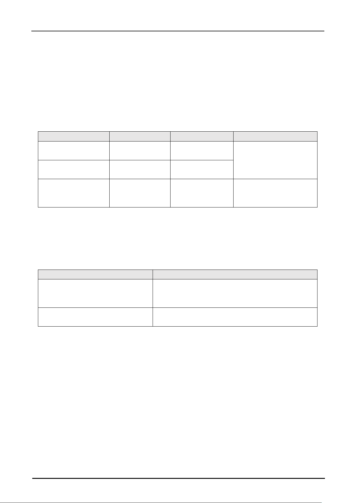
Set Sensor Head
Item
Setting range
Initial value
Note
Tolerance upper limit
value
measuring range
Maximum range
value
Tolerance setting value
should not exceed setting
range.
Tolerance lower limit
value
measuring range
Minimum range value
Measuring mode
Ordinary/transparent
object
Ordinary
Should adjust sensor head’s
tilt to measure transparent
object.
Set measurement parameters
Use filters to stabilize the measurement
HPS-LC010 provides follwing 2 filters:
Filter’s name
Function
Moving average filter
Calculate the moving average of the measured values and
set the number of measurements to obtain the average
value.
Median filter
Fluctuations of measuring result are prevented by ignoring
sudden changes in the measured values.
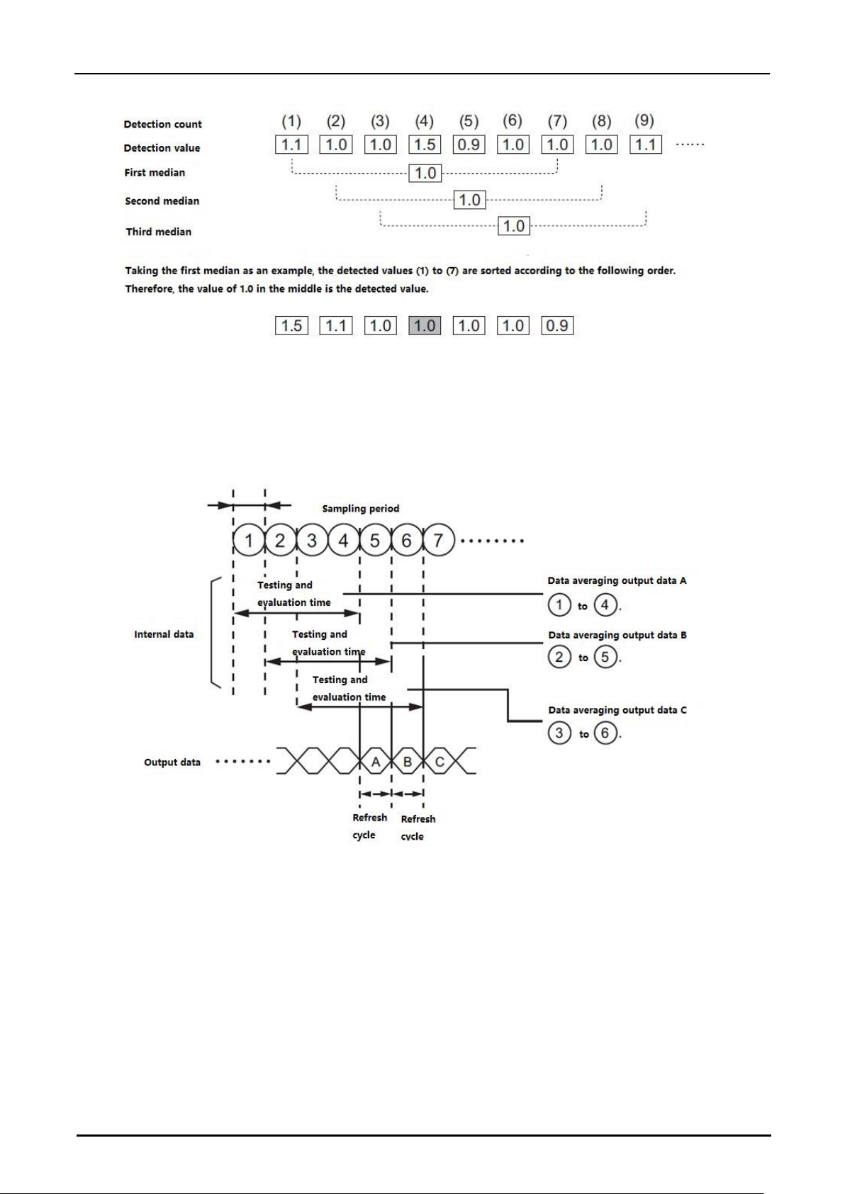
Set the median filter
This function uses a median filter of 7, 15, or 31 data to prevent fluctuations of measuring result by ignoring
sudden changes in the measured value. This function is useful when the target is moving quickly. This function
can be set by sending commands through the operation interface or communication interface.
Example when using 7 data median filters:
The 7 measuring results are alined according to the values, and the middle value is outputted as the result.
Page 19
Hypersen Technologies Co., Ltd. HPS-LC010
September 2018 Rev.1.1 19/70
Set the average filter
The average value filter calculates the moving average of the measured values in the range of 1 to 4096 times.
The following is an example of processing in which the average number of detection times is set to four. The
actual sampling period and refresh cycle vary depending on the different measuring materials.
Set measurement mode
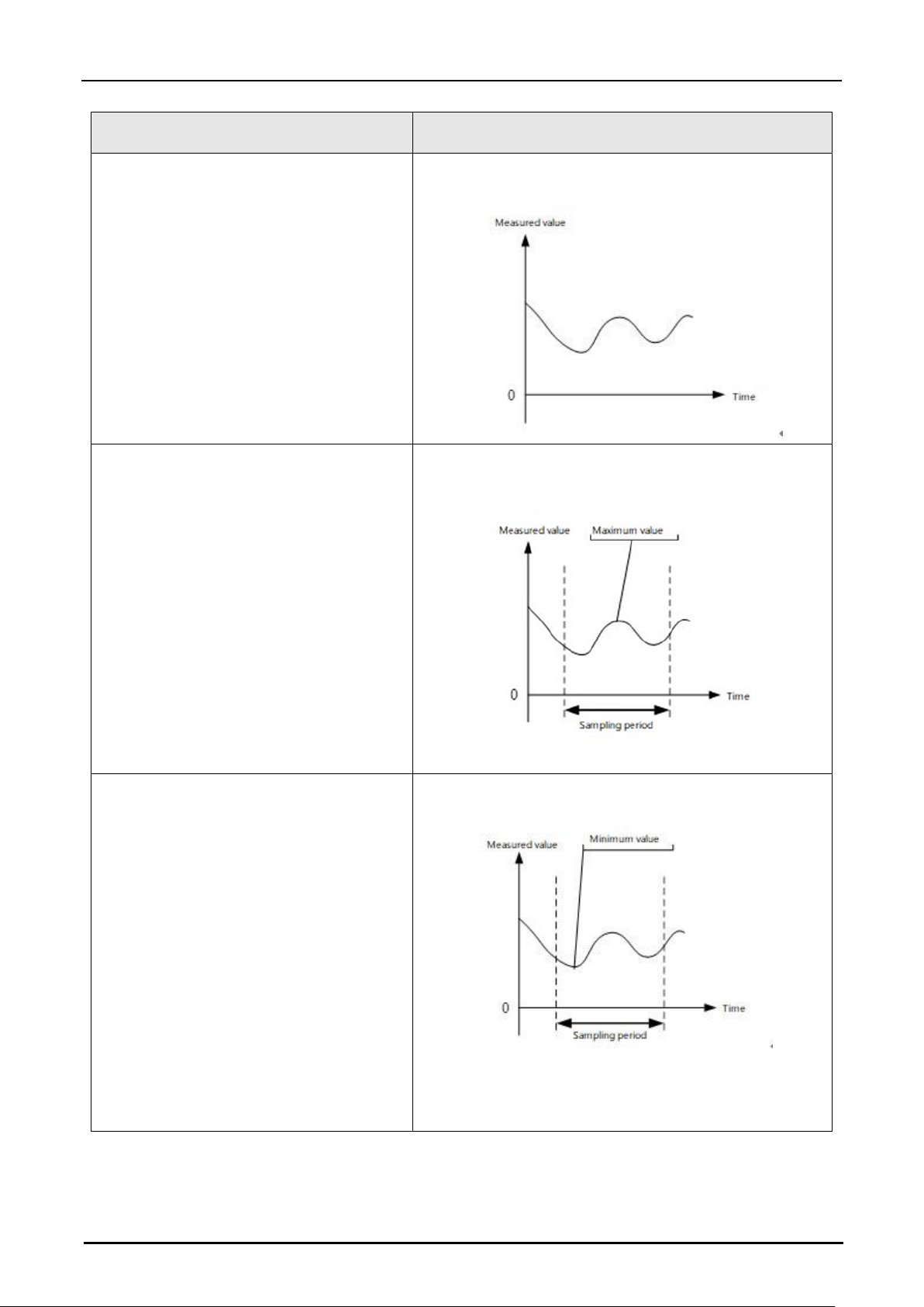
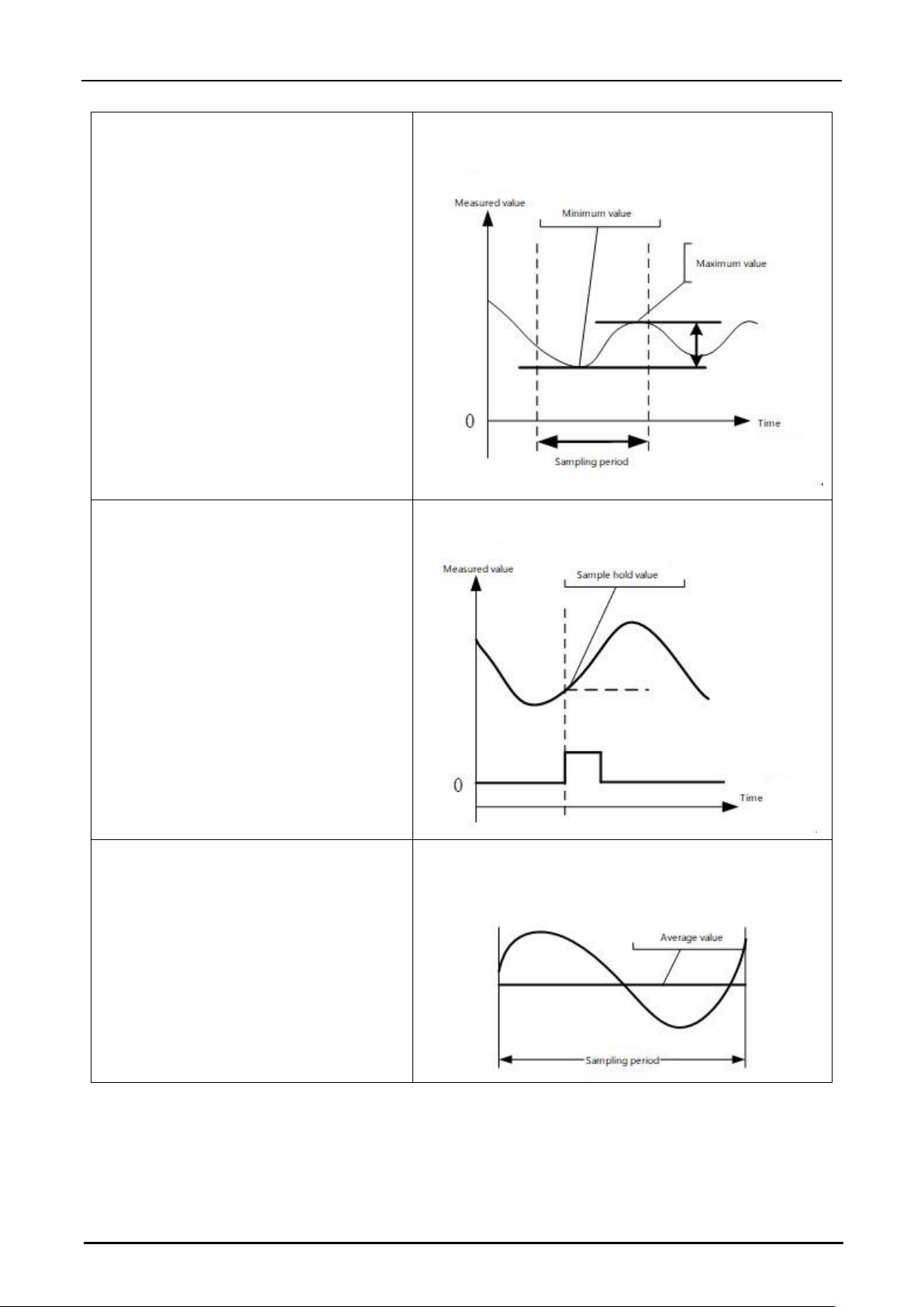
HPS-LC010 provides 6 measurement modes
Below chart introduce these measurement modes, set these modes through controller interface or
communication port command.
Page 20
Hypersen Technologies Co., Ltd. HPS-LC010
September 2018 Rev.1.1 20/70
Mode name
Description
Normal
Measurement results can be displayed/output
continuously
Hold peak
Measure maximum values during specified period
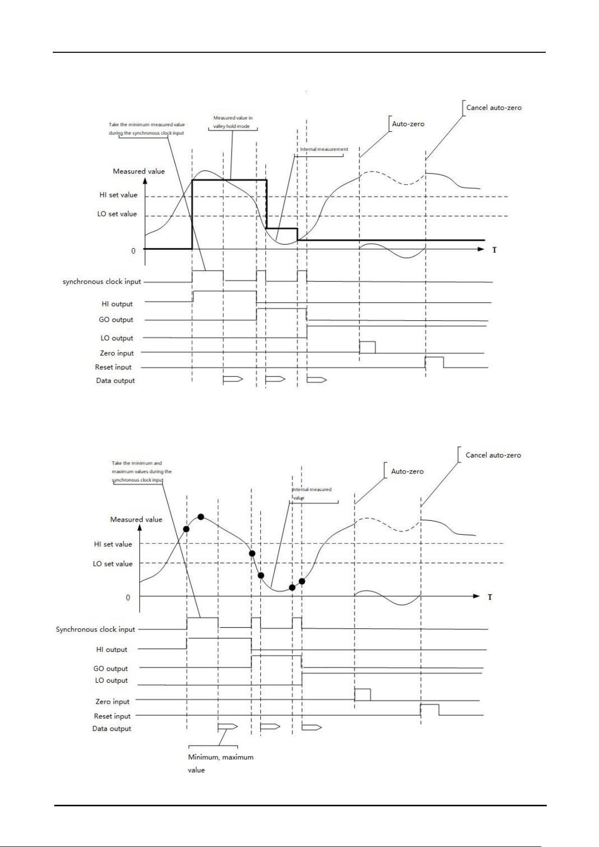
Hold valley
Measure minimum values during specified period
Page 21
Hypersen Technologies Co., Ltd. HPS-LC010
September 2018 Rev.1.1 21/70
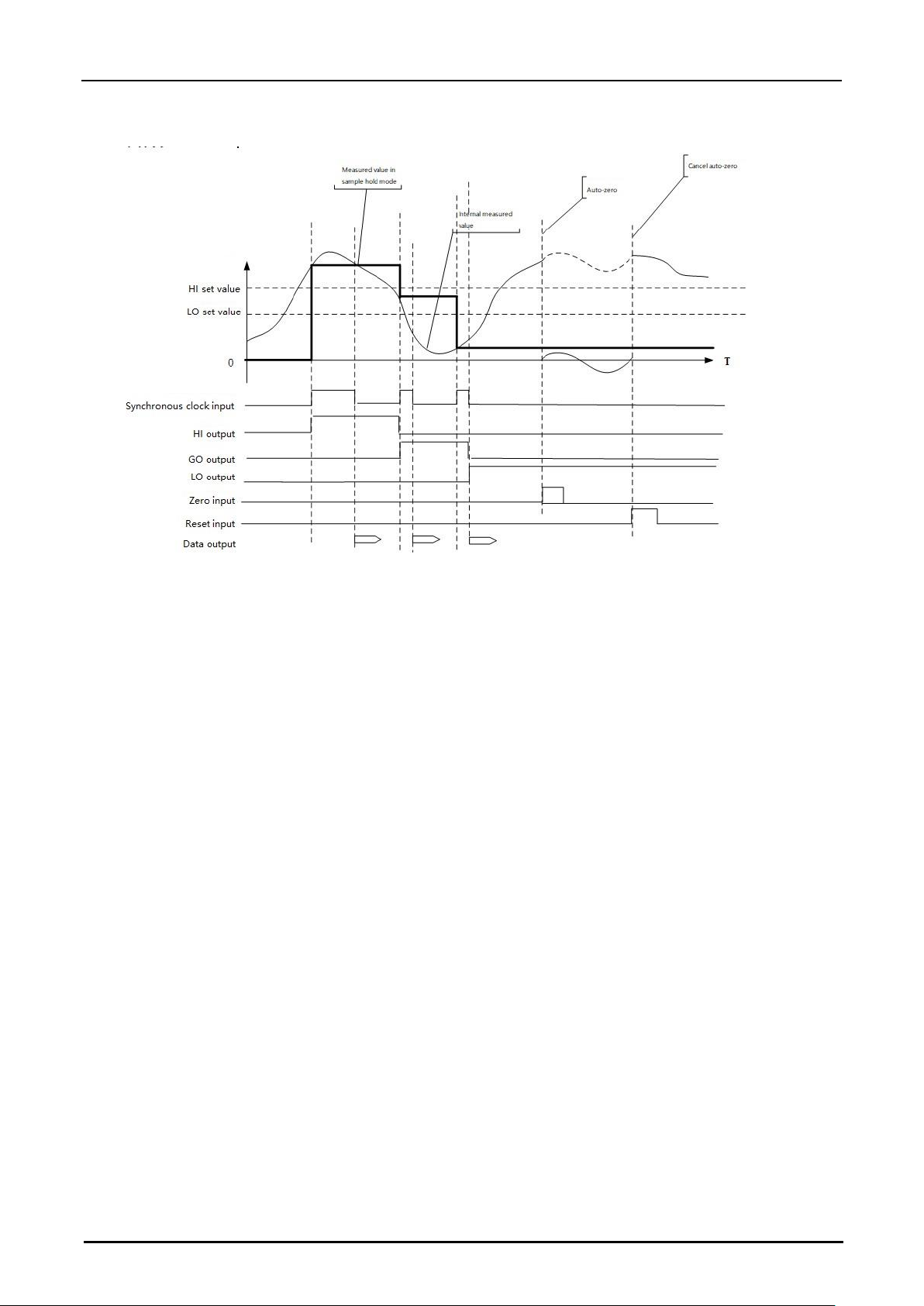
Peak-valley hold
Measure maximum and minimum values during specified
period
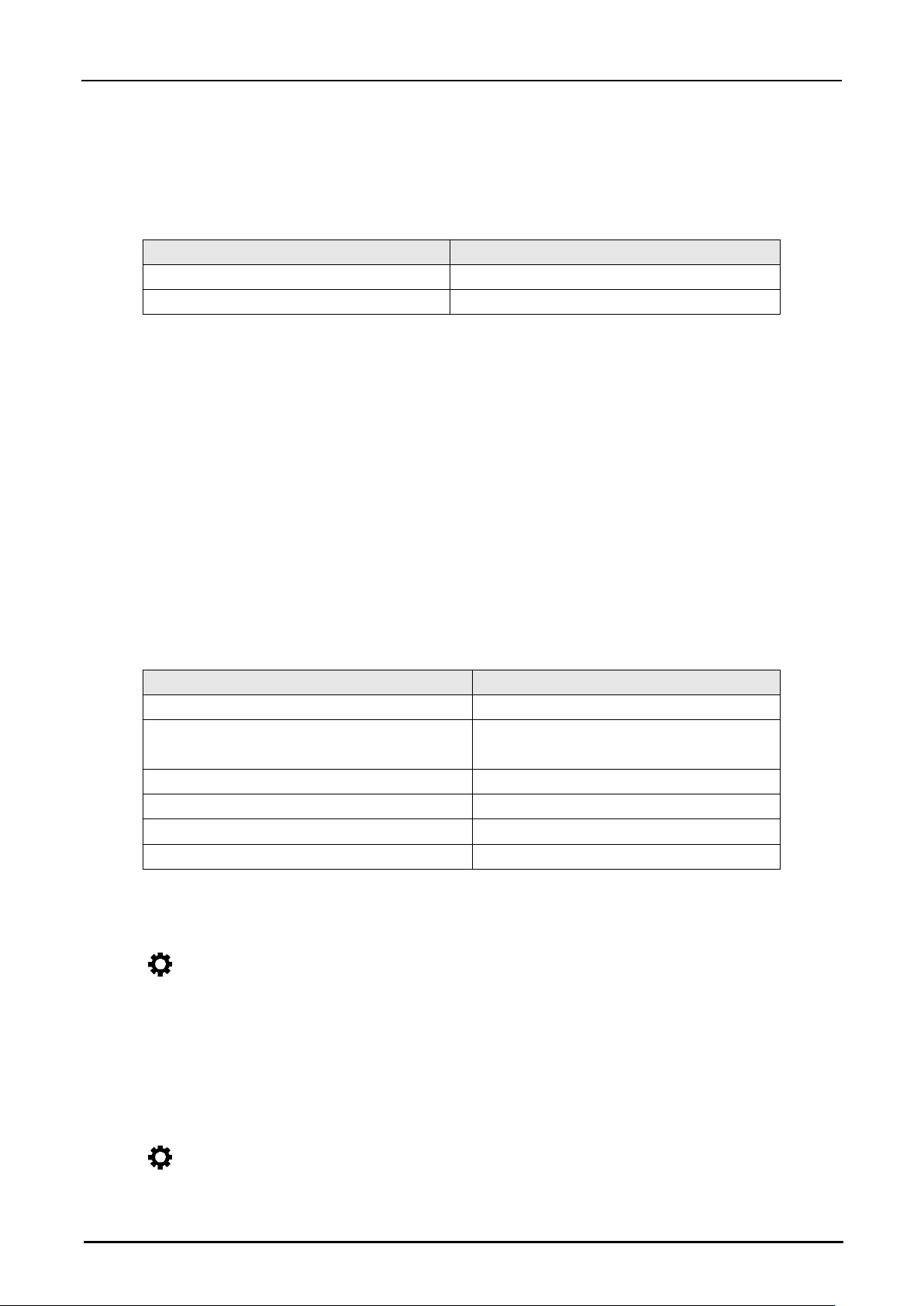
Sample hold
Measure specified moment’s value
Average hold
Measure average value during specified value
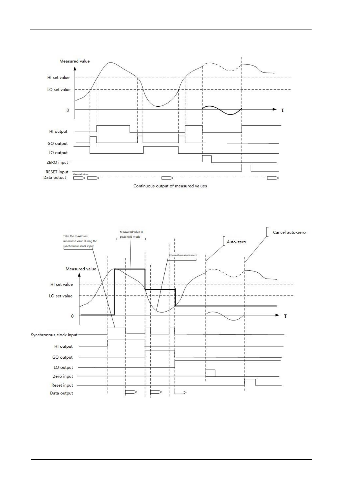
Note: Except normal mode, other five measurement modes require an input terminal configured for clock
synchronization.
Page 22
Hypersen Technologies Co., Ltd. HPS-LC010
September 2018 Rev.1.1 22/70
Normal mode
Note: The above figure shows an example where the level of the input/output port is set to active high.
Peak hold
Page 23
Hypersen Technologies Co., Ltd. HPS-LC010
September 2018 Rev.1.1 23/70
Valley hold
Peak-peak hold
Page 24
Hypersen Technologies Co., Ltd. HPS-LC010
September 2018 Rev.1.1 24/70
Sample hold
Data storage function
In the internal memory, HPS-LC010 can store up to 1,200,000 measured values. Send the command through
the communication interface to read the stored data.
This function stores the measured value in the controller's internal memory.
Up to 1,200,000 measurement point data can be stored in the internal memory for each synchronization input
signal duration or storage period. The measurement mode will determine whether to use "Synchronize with
sample period" or "Synchronize with sync input" mode when storing. You can use the communication interface
to send commands to start or stop the data storage. After the data is stored, it will not be lost until new storage
is started.
When the storage period is synchronized with the sampling period
1.The data can be stored according to the "condition for starting data storage (storage period)"
2.Stored measured values are determined by the "sampling period"
3.Measured results will be stored in the internal memory
4.Stop storing measurement data according to “Condition for stop data storage”
5.After the data storage function is stopped, the measurement result is no longer stored, and the controller sends
a "storage complete" data packet through the current communication interface.
When the storage period is "synchronous input"
1.Start storing measurement data according to “condition for starting data storage (External synchronization
input signal)”
2.Store measured values are determined by the "sampling period"
Page 25
Hypersen Technologies Co., Ltd. HPS-LC010
September 2018 Rev.1.1 25/70
3.Measured results will be stored in the internal memory
4.Stop storing measurement data according to “Condition for stop data storage”
5.After the data storage function is stopped, the measurement result is no longer stored, and the controller sends
a "storage complete" data packet through the current communication interface.
Storage period
Storage counting
x1
Store all measuring data
Synchronous input
Store data in every synchronous input
Set data storage
Send following commands through communication interface:
Command #13 set data storage configuration
Command #14 start data storage
The stored quantity can be obtained by command #15 in the stored procedure.
After the data storage is completed, the controller will automatically send a packet with RID 0xFE to indicate
that the storage is completed. At this time, the stored data can be obtained by using command #16.
Set Operation Environment
Function list and initial value
Function
Default
Backlight brightness
2/3 of maximum brightness value
Brightness maintenance time without
operation
300s
Touch screen auto lock time without operation
300s
Output warning
System warning
Language
English
Communication interface
Off
Set screen backlight brightness
1. Press button
2. Press System button
3. Drag Backlight slider to adjust the brightness
Send Command #22 to set backlight brightness through communication port
Set the backlight maintenance time
1. Press button
Page 26

Hypersen Technologies Co., Ltd. HPS-LC010
September 2018 Rev.1.1 26/70
2. Press S
ystem butto
n
3. Press Backlight input box, type in number (unit: second) on buttonboard, press Enter to confirm, press ESC
to cancel input
4. Press Set button to save the settings
Send Command #23 to set backlight overtime time through communication port
Set touch screen auto-lock time
1. Press button
2. Press System button
3. Press To uch Screen AutoLock input box, type in number (unit: second) on buttonboard, press Enter to confirm,
press ESC to cancel input
4. Press Set button to save the settings
Send Command #24 to set backlight auto-lock time through communication port
Set warning output
There are three warning sources: system warnings, overrange warnings, and all warnings.
System warning: When the hardware initialization fails or other hardware errors occur, the common problem
such as connection between the sensor head and the controller is abnormal, and the warning output will be
triggered.
Overrange warning: When the measured value is outside the measurement range, the warning output will be
triggered.
All warnings: The warning output is triggered when there is a system warning or an overrange warning.
The warning output can be set in the following two ways.
1. Press button
2. Press System button
3. Choose warning source
Send the command #21 via the communication interface to set.
Recalibrate the touch screen
1. Press button
2. Press System button
3. Press Calibrate button, the system will reboot and enter the screen calibration procedure
Set communication method
This function is used to set the communication interface between the controller and external devices. Three
communication interfaces are available: LAN, USB and UART.
Page 27

Hypersen Technologies Co., Ltd. HPS-LC010
September 2018 Rev.1.1 27/70
LAN settings
1. Press button
2. Press Communication button
3. Select LAN from Data output drop-down menu
4. Set the IP, subnet mask, and communication port number by pressing the edit box.
5. Press Set button to save the settings
USB-S settings
After the HPS-LC010 is connected to a PC, the USB-S interface will be virtualized as an Ethernet interface,
which makes the secondary development on PC much easier.
1. Make sure USB-S does not connect to external device, if connect, please disconnect the physical connection
2. Press button
3. Press Communication button
4. Choose USB-S from Data Output drop-down menu
5. Set the IP, subnet mask, and communication port number by pressing the edit box.
6. Wait for 3 seconds after pressing set button
7. Connect the controller to an external device using a USB-S cable
UART settings
1. Press button
2. Press Communication button
3. Choose UART from Data Output drop-down menu
4. Select the corresponding baud rate, number of data bits, parity and stop bits by Pressing the drop-down box.
5. Press Set button to save the settings
Page 28
Hypersen Technologies Co., Ltd. HPS-LC010
September 2018 Rev.1.1 28/70
Chapter 3 I/O Terminals
Names and Functions of the I/O Terminals
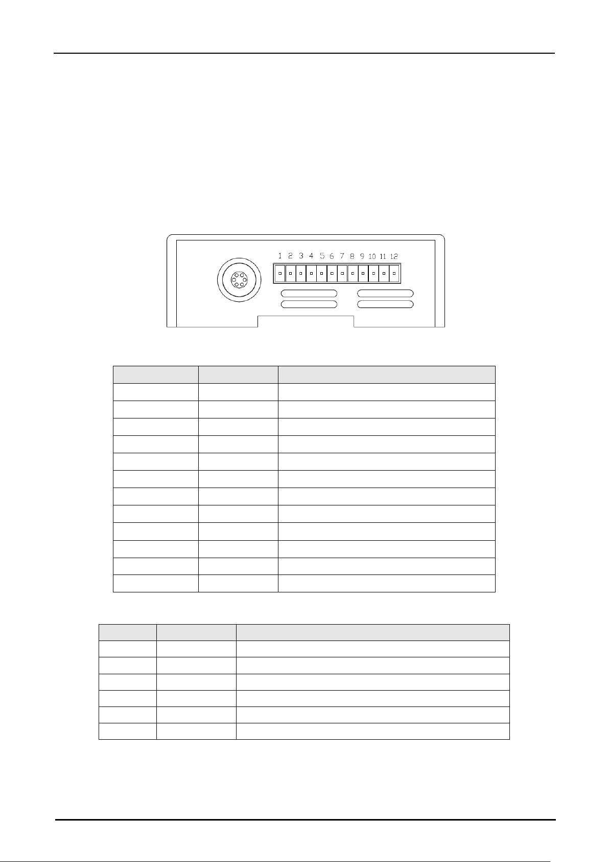
12-pin terminal block (Terminals)
Terminal Number
Signal definition
Description
1
COM_IN
COM for input
2
IN1
Input terminal 1
3
IN2
Input terminal 2
4
IN3
Input terminal 3
5
IN4
Input terminal 4
6
COM_OUT
COM for output
7
OUT1
Output terminal 1
8
OUT2
Output terminal 2
9
OUT3
Output terminal 3
10
Earth
Chassis ground
11
DC+
Power positive (DC 12V~26V, typical DC 24V)
12
DC-
Power negative
RS-232 Terminal Definition
Pin number
Terminal name
Description
1
NC
Not used
2
NC
Not used
3
TXD
Receive signal terminal (input)
4
GND
Signal ground
5
RXD
Transfer signal terminal (output)
6
NC
Not used
Page 29
Hypersen Technologies Co., Ltd. HPS-LC010
September 2018 Rev.1.1 29/70
• Precautions on wiring:
Parts of the input/output circuits of the product are common internally. Be careful that no potential difference
is generated between the internally common terminals due to the potential difference between the
cables/external devices. The COM OUT and COM IN terminals are common through choke coils and 24VDC
(-). Be careful of the potential difference being generated among these terminals. A connection error will result
in a malfunction of the product or an external device.
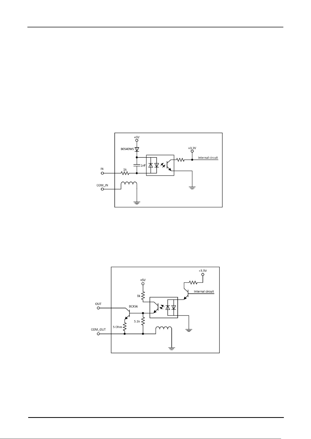
• Input port
The input terminals of the HPS-LC010 are non-voltage input type, and the COM_IN terminal is a common
terminal through a choke coil and 24V DC (-). When the IN and COM_IN terminals are short-circuited, the
COM_IN terminal is in the input state. If the IN terminal is to be operated in the voltage input mode, the maximum
input voltage is DC 28V. Exceeding this voltage will result in malfunction of the product or external equipment.
• Output port
The output terminals of the HPS-LC010 are NPN open-collector output type. The COM_OUT terminal is a
common terminal through a choke coil and 24V DC (-). The OUT terminal and the COM_OUT terminal are turned
on when the output signal is present. The maximum voltage diffenence between the OUT terminal and the
COM_OUT terminal is 80 V. The maximum current is 1 A. If the voltage or current exceed the above ranges, the
product or external device may malfunction.
• Electrical specifications for all type models
The 24VDC (-) terminal, the SG (GND) of the USB terminal, and the SG (GND) of the RS-232C interface become
the common terminal through
the choke coil. Please note that there is no potential difference between these
terminals and external devices such as a PC or PLC. If there is a potential difference, disconnect the I/O
terminals of any HPS-LC010 other than those used by the main power supply
, RS-232C, and USB.
Page 30
Hypersen Technologies Co., Ltd. HPS-LC010
September 2018 Rev.1.1 30/70
• Precautions for use in a positive grounding environment
When using the HPS-LC010 in a positive grounded environment, pay attention to the short circuit caused
by the COM terminal.
• Considerations for connecting a PC or other external device
In a positive groundi
ng environment, when connect a PC via USB or LAN, or when use a PC for RS-232C
communication, pay attention to a short circuit between the PC internal parts and the SG (GND) terminal
of the HPS-LC010. The 24VDC (-) terminal, the SG (GND) of the USB terminal, the SG (GND) and 24VDC
(-) of the RS-232C interface, and the SG (GND) of the LAN port become the common ground through the
corresponding chokes. Please note that there is no potential difference between these terminals and
external devices such as a PC or PLC. If there is a potential difference, disconnect any external devices
other than those used in the power supply, RS-232C, USB, and LAN, and the I/O terminals of the HPS-
LC010.
If the power supply terminal (24VDC) is short-circuited through the PC's internal parts and the HPSLC010's SG (GND) terminal, the product may malfunction. If this happens, disconnect the PC. The internal
wiring of the PC or PLC varies depending on the device.
Power Terminal
Name
Description
Protective ground terminal #10
Chassis ground, need to connect to ground
Power positive terminal #11
DC 12V-26V, typical DC 24V
Power negative terminal #12
Power negative flow back to ground
Function of the I/O signal
This section includes functions of the I/O signal.
Input
Name
Description
Input terminal #2 #3 #4 #5
Function and active polarity configurable input terminals
COM_IN terminal #1
COM IN terminal
Output
Name
Description
Output terminal #7 #8 #9
Function and active polarity configurable output terminals
COM_OUT terminal #6
COM OUT terminal
Input terminal configuration
The input terminals can simplify the use of common functions of the controller, especially devices which do not
have the LAN, USB or UART communication interfaces such as PLCs, which can greatly reduce the cost of use.
This product supports two configurations:
Set through the controller interface
1. Press the button
Page 31
Hypersen Technologies Co., Ltd. HPS-LC010
September 2018 Rev.1.1 31/70
2. Press I/O Port button
3. Press the Input Port tab and set the desired terminal
Note: When any input terminal is configured as "off" or "laser control function", if the input level signal does not
match the set polarity, the corresponding terminal status lights in red. When the input level signal is the same
as the set polarity, it lights in green. This feature is convenient for the user to debug the input terminals.
Set via communication interface (LAN, USB or UART)
1. Configure the communication interface in the controller interface
2. Configure via command #17
Configuration for Auto-Zero
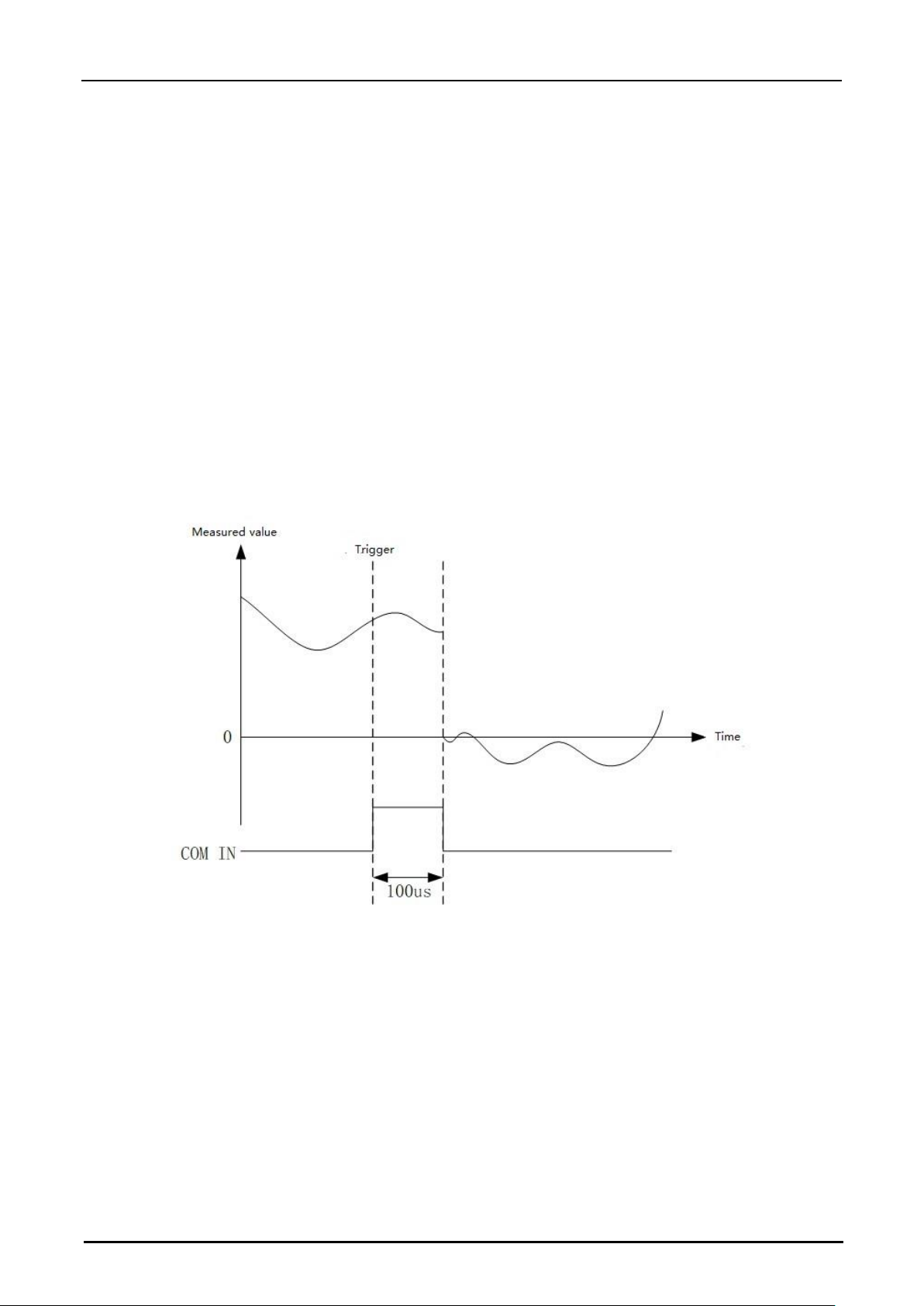
After the external device and the terminal are connected, when any input terminal is configured as an Auto-Zero
function input, only a level signal is required to trigger the Auto-Zero function of the measurement. When the
external devices do not have the LAN, USB or UART communication interfaces, this function will be very
convenient. Trigger mode can be configured as rising edge or falling edge trigger.
Timing diagram (when using rising edge trigger)
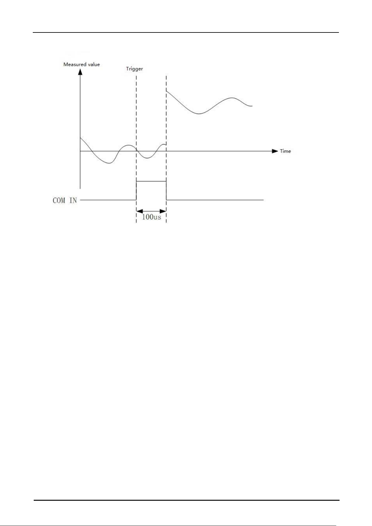
Configuration for Cancel Auto-Zero function
After the external device and the terminal are connected, when any input terminal is configured as Cancel AutoZero function, only a level signal is required to trigger the Cancel Auto-Zero function. When the external devices
do not have the LAN, USB or UART communication interfaces, this function will be very convenient. Trigger
mode can be configured as rising edge or falling edge trigger.
Page 32
Hypersen Technologies Co., Ltd. HPS-LC010
September 2018 Rev.1.1 32/70
Timing diagram (when using rising edge trigger)
Configuration for Clock Synchronization function
After the external device and the terminal are connected, when any input terminal is configured as Clock
Synchronization function, only a level signal is required to trigger the Clock Synchronization function. When the
external devices do not have the LAN, USB or UART communication interfaces, this function will be very
convenient. Trigger mode can be configured as rising edge or falling edge trigger.
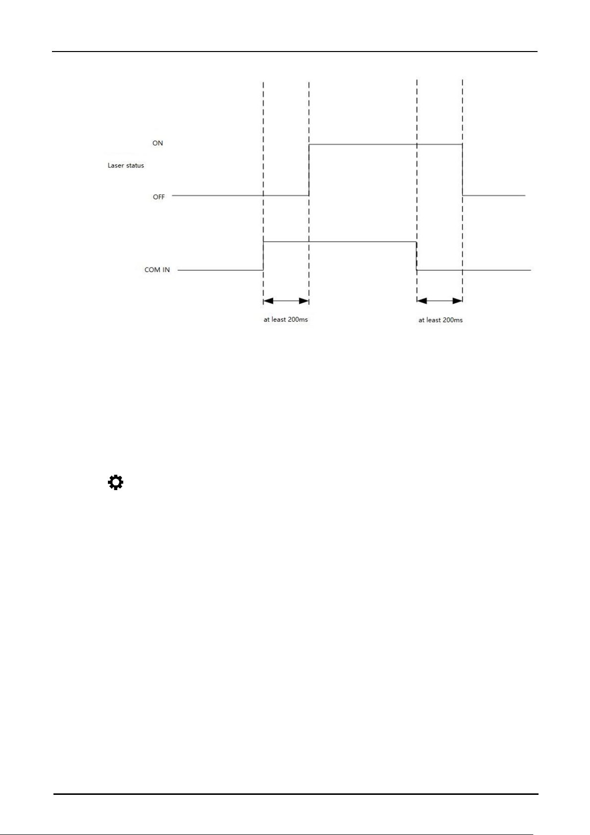
Configuration for Laser Control function
After the external device and the terminal are connected, when any input terminal is configured as Laser Control
function, only a level signal is required to trigger the Laser Control function. When the external devices do not
have the LAN, USB or UART communication interfaces, this function will be very convenient. Trigger mode can
be configured as rising edge or falling edge trigger.
Page 33
Hypersen Technologies Co., Ltd. HPS-LC010
September 2018 Rev.1.1 33/70
Timing diagram (when using high level trigger)
Output Terminal Configuration
The output terminals can provide signal prompts during measurement. Some functions of the output terminals
need to be used with a tolerance comparator. This product supports two configurations:
Set through the controller interface
1.Press the button
2. Press I/O Port button
3. Press the Output Port tab and set the desired terminal
Note: The signal polarity of the output terminals depends on the output terminal polarity settings.
Set via communication interface (LAN, USB or UART)
1. Configure the communication interface in the controller interface
2. Configure via command #18
Configuration for GO output
When the measured value is between the tolerance upper limit value and the tolerance lower limit value, the
configured output terminal outputs a GO signal.
Configuration for HI output
When the measured value is greater than the tolerance upper limit, the configured output terminal outputs a HI
signal.
Page 34
Hypersen Technologies Co., Ltd. HPS-LC010
September 2018 Rev.1.1 34/70
Configuration for LO output
When the measured value is lower than the tolerance lower limit, the configured output terminal outputs the LO
signal.
Configuration for ALARM output
When the system warning or over-range warning occurs, the configured output terminal outputs an ALARM
signal. The source of the warning depends on the settings of the warning output.
Timing diagram (when using high level trigger)
Chapter 4 Firmware upgrade
This product supports firmware upgrade function. Once the product's firmware is updated, it means that
some bugs have been fixed or the performance has been improved. Please refer to the official website of
Hypersen Technology (Shenzhen) Co., Ltd.: http://www.hypersen.com to see if there is a new firmware
released.
Upgrade the firmware using the latest version of the LC-010 client software on PC, which supports the
upgrading via LAN, USB or UART interfaces. Note: Before the firmware upgrading, make sure that the
power supply is stable. If the power is interrupted during the upgrading, the sensor firmware may be
damaged. Please refer to the the LC-010 client software operating instructions for details.
Note: Due to the influence of the serial communication speed, if UART is used as the upgrading interface,
it requires more time than using LAN or USB interfaces.
Page 35
Hypersen Technologies Co., Ltd. HPS-LC010
September 2018 Rev.1.1 35/70
Chapter 5 Communication Command
This chapter describes the format of commands which can be used to communicate with the controller. The
command can be received by the controller during measurement, and the controller will send back a command
response after correctly processing the received command.
Note: 1. For all communication interfaces (LAN, USB, and UART), the commands and returned data formats
are the same. 2. For values greater than one byte, both the command parameters and the returned value follow
the “high byte first” format, for example:
If a parameter or returned value is 0x12345678, N [0] =0x12, N [1] = 0x34, N [2] = 0x56, N [3] = 0x78
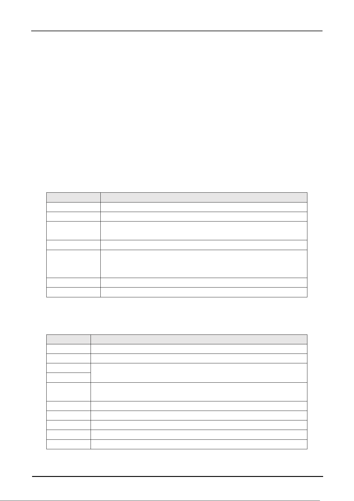
Command and returned data format
The length of command is not fixed, which is composed of header + message length + message + CRC16. The
details are as below:
Byte Number
Description
0
0x3F Header 1
1
0xF3 Header 2
2
N=3~255, indicating the remaining data length, at least 1 command byte and
2 CRC bytes
3
Command byte, participate in CRC16 check
N-3 byte
command
parameter
Parameter,
participate in CRC16 check
3+N-2
CRC high byte
3+N-1
CRC low byte
The returned data of the sensor is a variable length format, which is composed of header + message length +
message + CRC16 + message end. The details are as follows:
Byte Number
Description
0
0x5F Header 1
1
0xF5 Header 2
2
N=6~255, indicating the remaining data length, at least 1 RID byte, 1 reply byte,
2 trailing bytes and 2 CRC value bytes
3
4
RID byte, used to indicated returned data packet type, this byte is included in
CRC16 calculation
…
N-5 return data, this byte is included in CRC16 calculation
4+(N-4)
CRC high byte
4+(N-3)
CRC low byte
4+(N-2)
0xF5
4+(N-1)
0x5F
Page 36
Hypersen Technologies Co., Ltd. HPS-LC010
September 2018 Rev.1.1 36/70
Commands
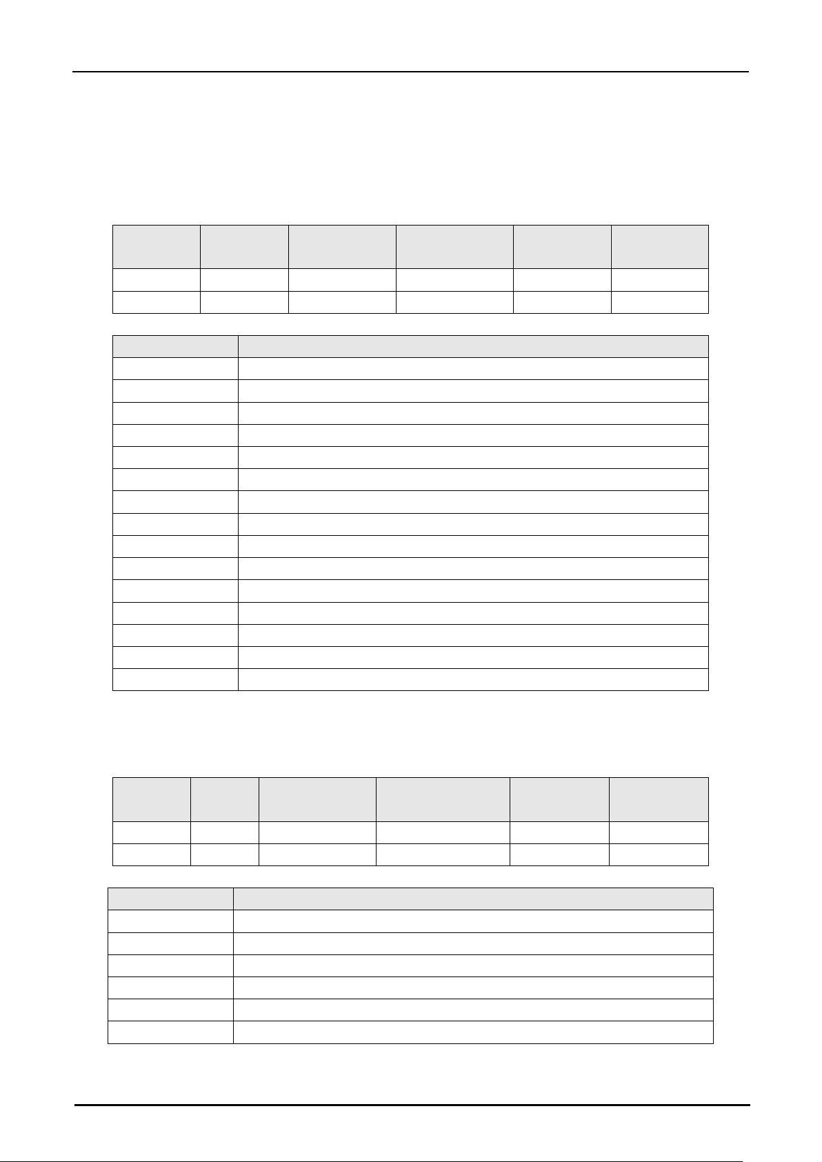
Command #1 Read Controller Version Information
This command is used to read controller software version information
Header 1
Header 2
Message
length
Command
bytes
CRC high
byte
CRC low
byte
Byte0
Byte1
Byte2
Byte3
Byte4
Byte5
0x3F
0xF3
0x3
0xA2
0x74
0x58
Returned data:
Byte number
Description
0
0x5F: Header 1
1
0xF5: Header 2
2
0x00: Message length high byte
3
0x0B: Message length low byte
4
0xA2: RID byte
5
Year, for example: 18 indicates 2018, in Hex is 0x12
6
Month
7
Day
8
Major version
9
Small version
10
Amendment No.
11
CRC high byte
12
CRC low byte
13
0xF5: Message end 1
14
0x5F: Message end 2
Command #2 Read DSP Algorithm Version Information
This command is used to read DSP algorithm version information
Header 1
Header
2
Message length
Command byte
CRC high
byte
CRC low
byte
Byte0
Byte1
Byte2
Byte3
Byte4
Byte5
0x3F
0xF3
0x3
0xA4
0x14
0x9E
Returned data:
Byte number
Description
0
0x5F: Header 1
1
0xF5: Header 2
2
0x00: Message length high byte
3
0x0B: Message length low byte
4
0xA4: RID byte
5
Year, for example: 18 indicates 2018, in Hex is 0x12
Page 37
Hypersen Technologies Co., Ltd. HPS-LC010
September 2018 Rev.1.1 37/70
6
Month
7
Day
8
Major version
9
Small version
10
Ammendment No.
11
CRC high byte
12
CRC low byte
13
0xF5: Message end 1
14
0x5F: Message end 2
Command #3 Read Sensor Head Version Information
This command is used to read sensor head version information
Header 1
Header 2
Message
length
Command
byte
CRC high
byte
CRC low
byte
Byte0
Byte1
Byte2
Byte3
Byte4
Byte5
0x3F
0xF3
0x3
0xA3
0x64
0x79
Returned data:
Byte number
Description
0
0x5F: Header 1
1
0xF5: Header 2
2
0x00: Message length high byte
3
0x06: Message length low byte
4
0xA3: RID byte
5
Version number
6
CRC high byte
7
CRC low byte
8
0xF5: Message end 1
9
0x5F: Message end 2
Command #4 Set Zero-Offset Value
This command is used to set the zero-offset value. The setting values will be automatically saved to the internal
non-volatile memory and reloaded with each power up. The zero value of the parameter = the real value
*1000000.
Byte number
Description
0
0x3F: Header 1
1
0xF3: Header 2
2
0x08: Message length
3
0xB5: Command byte
4
0x01: Confirmation byte
5
Zero-offset value [31:24]
6
Zero-offset value [23:16]
Page 38
Hypersen Technologies Co., Ltd. HPS-LC010
September 2018 Rev.1.1 38/70
7
Zero-offset value [15:8]
8
Zero-offset value [7:0]
9
CRC high byte
10
CRC low byte
Returned data:
Byte number
Description
0
0x5F: Header 1
1
0xF5: Header 2
2
0x00: Message length high byte
3
0x06: Message length low byte
4
0xB5: RID byte
5
0x01: Confirmation byte
6
CRC high byte
7
CRC low byte
8
0xF5: Message end 1
9
0x5F: Message end 2
Command #5 Auto-Zero or Cancel Auto-Zero
This command is use to active or cancel the auto-zero function.
The setting values will be automatically
saved to the internal non-volatile memory and reloaded with each power up.
Byte number
Description
0
0x3F: Header 1
1
0xF3: Header 2
2
0x04: Message length high byte
3
0xBB: Command byte
4
0x01: Auto-zero, 0x2: Cancel auto-zero
5
CRC high byte
6
CRC low byte
Returned data:
Byte number
Description
0
0x5F: Header 1
1
0xF5: Header 2
2
0x00: Message length high byte
3
0x06: Message length low byte
4
0xBB: RID byte
5
0x01: Confirmation byte
6
CRC high byte
7
CRC low byte
8
0xF5: Message end 1
9
0x5F: Message end 2
Page 39
Hypersen Technologies Co., Ltd. HPS-LC010
September 2018 Rev.1.1 39/70
Command #6 Read Current Zero-Offset Value
This command is used to read the current Zero-offset value. The returned value = real value *1000000.
Header1
Header2
Message
length
Command
byte
CRC high
byte
CRC Low
byte
Byte0
Byte1
Byte2
Byte3
Byte4
Byte5
0x3F
0xF3
0x3
0xA7
0x24
0xFD
Returned data:
Byte number
Description
0
0x5F: Header 1
1
0xF5: Header 2
2
0x00: Message length high byte
3
0x09: Message length low byte
4
0xA7: RID byte
10
offset value [31:24]
11
offset value [16:23]
12
offset value [15:8]
13
offset value [7:0]
14
CRC high byte
15
CRC low byte
16
0xF5: Message end 1
17
0x5F: Message end 2
Command #7 Single Measurement
This command is used to read a frame of measured result from the controller, returned value = real value
*1000000.
Header1
Header2
Message
length
Command
value
CRC High
byte
CRC Low
byte
Byte0
Byte1
Byte2
Byte3
Byte4
Byte5
0x3F
0xF3
0x3
0xA1
0x44
0x3B
Returned data:
Byte number
Description
0
0x5F: Header 1
1
0xF5: Header 2
2
0x00: Message length high byte
3
0x09: Message length low byte
4
0xA1: RID byte
10
Measured value [31:24]
11
Measured value [16:23]
12
Measured value [15:8]
13
Measured value [7:0]
14
CRC high byte
Page 40
Hypersen Technologies Co., Ltd. HPS-LC010
September 2018 Rev.1.1 40/70
15
CRC low byte
16
0xF5: Message end 1
17
0x5F: Message end 2
Command #8 Continuous Measurement
This command is used to activate the controller to continuously output the measured results. The returned value
= real value *1000000.
Header1
Header2
Message
length
Command
byte
Parameters
CRC High
byte
CRC Low
byte
Byte0
Byte1
Byte2
Byte3
Byte4
Byte5
Byte6
0x3F
0xF3
0x4
0xA6
0x00: ON
0x01: OFF
Depends on
parameters
Depends on
parameters
Returned data:
Byte number
Description
0
0x5F: Header 1
1
0xF5: Header 2
2
0x00: Message length high byte
3
0x06: Message length low byte
4
0xA6: RID byte
5
0x01: Confirmation byte
6
0xBA: CRC high byte
7
0xF6: CRC low byte
8
0xF5: Message end 1
9
0x5F: Message end 2
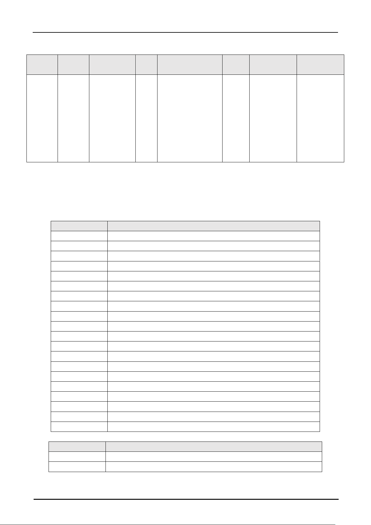
In the continuous measurement mode, the controller continuously outputs the measured values via the selected
communication interface (USB, LAN or UART), RID = 0xFD, a data packet may contain multiple measured
values. When decoding the data, the number of measured values in the data packet need to be calculated by
the message length. The format of output packet in normal measurement mode, peak hold mode, valley hold
mode, sample hold mode, and average hold mode is as below:
Header1
Header2
Message
length
RID
Measured value
CRC16
Message end
1
Message end
2
0x5F
0xF5
[15:0]
0xFD
Measured value
1[31:0]
Measured value
2[31:0]
…
Measured value
n[31:0]
[15:0]
0xF5
0x5F
Page 41
Hypersen Technologies Co., Ltd. HPS-LC010
September 2018 Rev.1.1 41/70
In peak-peak hold mode, the format of data packet is as below:
Header1
Header2
Message
length
RID
Measured value
CRC16
Message end
1
Message end
2
0x5F
0xF5
[15:0]
0xFD
Minimum value
1[31:0]
Maximum value
1[31:0]
…
Minimum value
n[31:0]
Maximum value
n[31:0]
[15:0]
0xF5
0x5F
Command #9 Program Setting
This command is used to set the tolerance range and zero-offset value for a specified program. The parameter
value (tolerance upper limit / tolerance lower limit /zero-offset value) = actual value *1000000. The setting values
will be automatically saved to the internal non-volatile memory and reloaded with each power up.
Byte number
Description
0
0x3F: Header 1
1
0xF3: Header 2
2
0x11: Message length high byte
3
0xA8: Command byte
4
0x00: Read, 0x01: Set
5
Program No. 1~9, for read command only program No. is required
6
Tolerance upper limit [31:24]
7
Tolerance upper limit [16:23]
8
Tolerance upper limit [8:15]
9
Tolerance upper limit [0:7]
10
Tolerance lower limit [31:24]
11
Tolerance lower limit [16:23]
12
Tolerance lower limit [8:15]
13
Tolerance lower limit [0:7]
14
Zero-offset value [31:24]
15
Zero-offset value [23:16]
16
Zero-offset value [15:8]
17
Zero-offset value [7:0]
18
CRC high byte
19
CRC low byte
Returned data of Set Command:
Byte number
Description
0
0x5F: Header 1
1
0xF5: Header 2
Page 42

Hypersen Technologies Co., Ltd. HPS-LC010
September 2018 Rev.1.1 42/70
2
0x00: Message length high byte
3
0x06: Message length low byte
4
0xA8: RID byte
5
0x01: Confirmation byte
6
0x99: CRC high byte
7
0xF9: CRC low byte
8
0xF5: Message end 1
9
0x5F: Message end 2
Returned data of Read Command:
Byte number
Description
0
0x5F: Header 1
1
0xF5: Header 2
2
0x00: Message length high byte
3
0x12: Message length low byte
4
0xA8: RID byte
5
Program No.
6
Tolerance upper value [31:24]
7
Tolerance upper value [23:16]
8
Tolerance upper value [15:8]
9
Tolerance upper value [7:0]
10
Tolerance lower value [31:24]
11
Tolerance lower value [23:16]
12
Tolerance lower value [15:8]
13
Tolerance lower value [7:0]
14
Zero-offset [31:24]
15
Zero-offset [23:16]
16
Zero-offset [15:8]
17
Zero-offset [7:0]
18
CRC high byte
19
CRC low byte
20
0xF5: Message end 1
9
0x5F: Message end 2
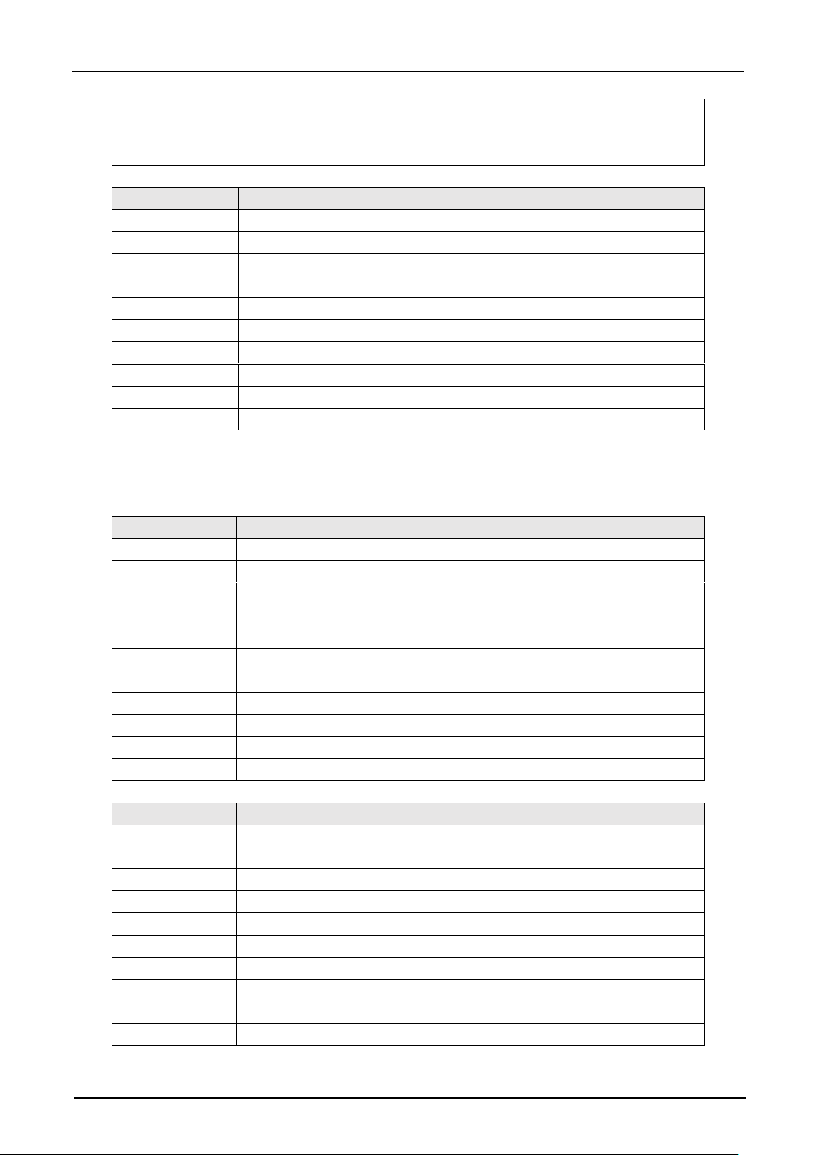
Command #10 Set or Read Current Program Number
This command is used to set or read the current program number. The setting values will be automatically saved
to the internal non-volatile memory and reloaded with each power up.
Byte number
Description
0
0x3F: Header 1
1
0xF3: Header 2
2
0x05: Message length
3
0xB3: Command byte
4
0x00: Read, 0x01: Set
Page 43
Hypersen Technologies Co., Ltd. HPS-LC010
September 2018 Rev.1.1 43/70
5
Program number 0~9, for read command, this byte can be neglected
11
CRC high byte
12
CRC low byte
Returned data:
Byte number
Description
0
0x5F: Header 1
1
0xF5: Header 2
2
0x00: Message length high byte
3
0x06: Message length low byte
4
0xB3: RID byte
5
For the read command, this byte is program number, otherwise it is 0x01
6
CRC high byte
7
CRC low byte
8
0xF5: Message end 1
9
0x5F: Message end 2
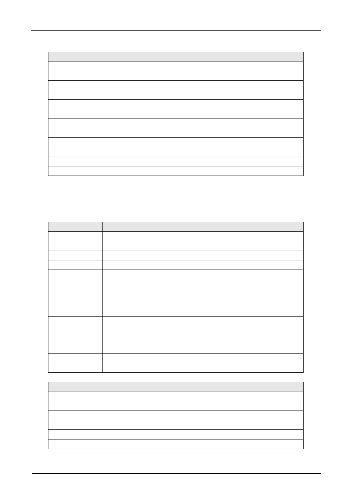
Command #11 Set or Read Laser Status
This command is used to set laser's ON/OFF or read the laser status.
Byte number
Description
0
0x3F: Header 1
1
0xF3: Header 2
2
0x07: Message length
3
0xA9: Command byte
4
0x00: Read, 0x01: Set
5
0x00: laser OFF, 0x01: laser ON; For read command, this byte can be
neglected
6
Reserved, 0x00. For read command, this byte can be neglected
7
Reserved, 0x00. For read command, this byte can be neglected
8
CRC high byte
9
CRC low byte
Returned data of Set Command:
Byte No.
Description
0
0x5F: Header 1
1
0xF5: Header 2
2
0x00: Message length High byte
3
0x06: Message length Low byte
4
0xA9: RID byte
5
0x01: Confirmation byte
6
CRC High byte
7
CRC Low byte
8
0xF5: Message end 1
9
0x5F: Message end 2
Page 44
Hypersen Technologies Co., Ltd. HPS-LC010
September 2018 Rev.1.1 44/70
Returned data of Read Command:
Byte No.
Description
0
0x5F: Header 1
1
0xF5: Header 2
2
0x00: Message length high byte
3
0x08: Message length low byte
4
0xA9: RID byte
5
0x00: Laser is OFF status, 0x01: Laser is ON status
6
Arbitrary value, reserved
7
Arbitrary value, reserved
8
CRC high byte
9
CRC low byte
10
0xF5: Message end 1
11
0x5F: Message end 2
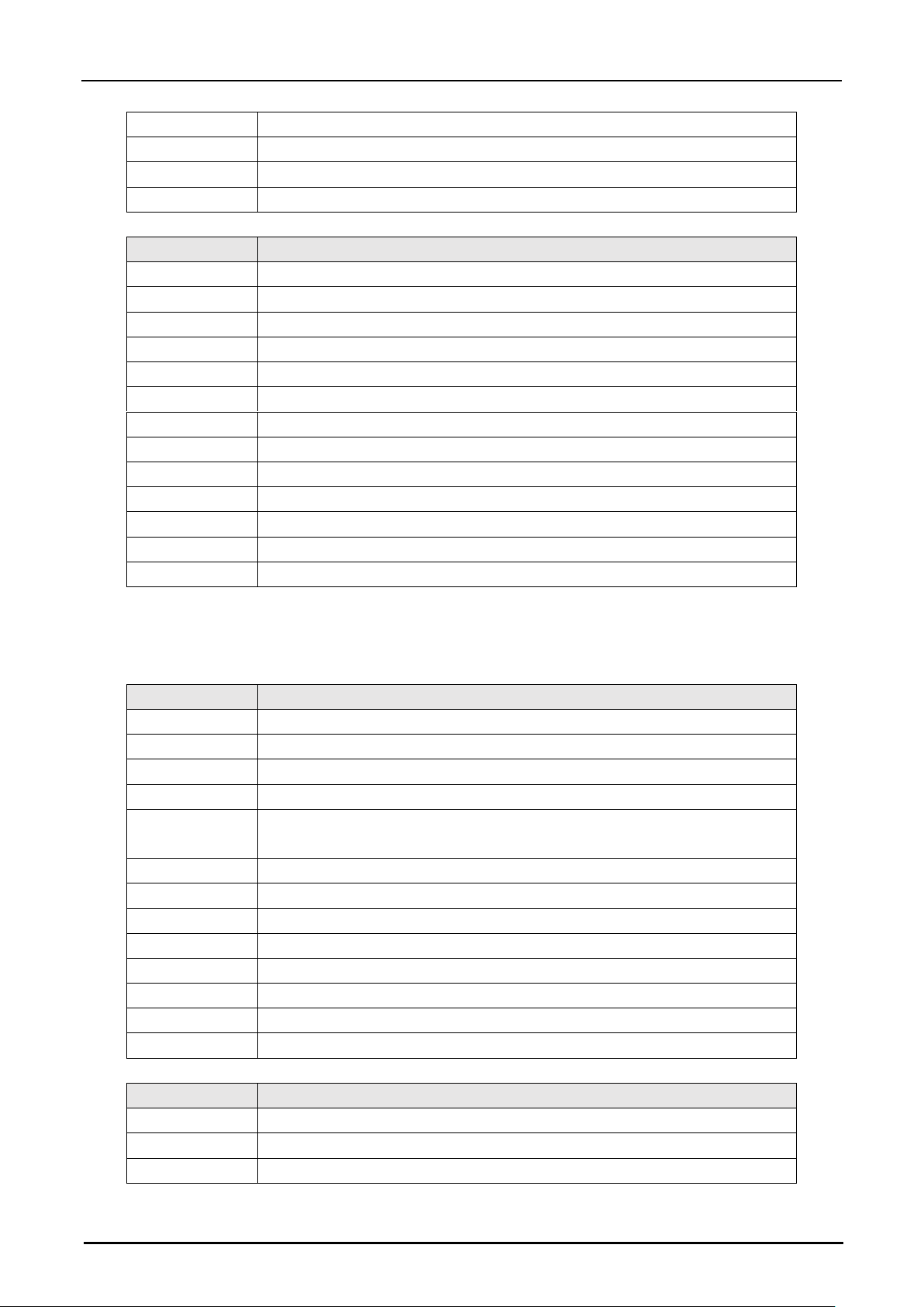
Command #12 Set or read measurement mode
This command is used to set or read the current measurement mode. The setting values will be automatically
saved to the internal non-volatile memory and reloaded with each power up.
Byte No.
Description
0
0x3F: Header1
1
0xF3: Header2
2
0x06: Message length
3
0xAC: Command byte
4
0x01: Set, 0x00: Read
5
Measurement mode:
0x01: normal mode 0x02: peak hold 0x03: valley hold 0x04: peak-peak hold
0x05: sampling hold 0x06: average hold;
For read command, this byte can be neglected.
6
Material:
0x01: ordinary 0x02: transparent 0x03: reserve 0x04: reserve 0x05:
reserved.
For read command, this byte can be neglected.
7
CRC high byte
8
CRC low byte
Returned data of Set Command:
Byte No.
Description
0
0x5F: Header 1
1
0xF5: Header 2
2
0x00: Message length high byte
3
0x06: Message length low byte
4
0xAC: RID byte
5
0x01: Confirmation byte
Page 45
Hypersen Technologies Co., Ltd. HPS-LC010
September 2018 Rev.1.1 45/70
6
CRC high byte
7
CRC low byte
8
0xF5: Message end 1
9
0x5F: Message end 2
Returned data of Read Command:
Byte No.
Description
0
0x5F: Header 1
1
0xF5: Header 2
2
0x00: Message length high byte
3
0x09: Message length low byte
4
0xAC: RID byte
5
0x01: Confirmation byte
6
Measurement mode
7
Material
8
Reserved
9
CRC high byte
10
CRC low byte
11
0xF5: Message end 1
12
0x5F: Message end 2
Command #13 Set or Read Data Storage Parameters
This command is used to set or read the current data storage parameters, such as the number of storage points.
Byte No.
Description
0
0x3F: Header 1
1
0xF3: Header 2
2
0x0A: Message length
3
0xAF: Command byte
4
0x01: Set, 0x03: Read. For read command, storage quantity and reserved
byte can be neglected.
5
Storage quantity [31:24]
6
Storage quantity [23:16]
7
Storage quantity [15:8]
8
Storage quantity [7:0]
9
Reserved
10
Reserved
11
CRC high byte
12
CRC low byte
Returned data of Set Command:
Byte No.
Description
0
0x5F: Header 1
1
0xF5: Header 2
2
0x00: Message length high byte
Page 46
Hypersen Technologies Co., Ltd. HPS-LC010
September 2018 Rev.1.1 46/70
3
0x06: Message length low byte
4
0xAF: RID byte
5
0x01: Confirmation byte
6
CRC high byte
7
CRC low byte
8
0xF5: Message end 1
9
0x5F: Message end 2
Returned data of Read Command:
Byte No.
Description
0
0x5F:Header1
1
0xF5:Header2
2
0x00: Message length High byte
3
0x12: Message length Low byte
4
0xAF: RID byte
5
0x00: Currently in stop storage status
0x01: Currently in storage status
6
Set storage quantity [31:24]
7
Set storage quantity [23:16]
8
Set storage quantity [15:8]
9
Set storage quantity [7:0]
10
Reserved
11
Reserved
12
CRC high byte
13
CRC low byte
14
0xF5: Message end 1
15
0x5F: Message end 2
Command #14 Start or Stop Data Storage
This command is used to start or stop data storage. After the storage parameters are configured, user needs to
send this command to start data storage.
Byte No.
Description
0
0x3F: Header 1
1
0xF3: Header 2
2
0x06: Message length
3
0xAF: Command byte
4
0x02
5
0x00: Stop storage, 0x01: Start storage
6
0x00: Delete old data, 0x01: Add the new data just after the end of old data
7
CRC high byte
8
CRC low byte
Page 47
Hypersen Technologies Co., Ltd. HPS-LC010
September 2018 Rev.1.1 47/70
Returned data of Set Command:
Byte No.
Description
0
0x5F: Header 1
1
0xF5: Header 2
2
0x00: Message length high byte
3
0x06: Message length low byte
4
0xAF: RID byte
5
0x01: Confirmation byte
6
CRC high byte
7
CRC low byte
8
0xF5: Message end 1
9
0x5F: Message end 2
When the data storage length reaches the set value, the storage will be automatically triggered to stop, and the
controller will send a “storage completed” data packet to the external device through the communication interface.
The format of the data packet is:
Byte No.
Description
0
0x5F: Header 1
1
0xF5: Header 2
2
0x00: Message length high byte
3
0x06: Message length low byte
4
0xFE: RID byte
5
0x01: Confirmation byte
6
CRC high byte
7
CRC low byte
8
0xF5: Message end 1
9
0x5F: Message end 2
Command #15 Read Saved Data
This command is used to read the stored measurement data.
Byte No.
Description
0
0x3F: Header 1
1
0xF3: Header 2
2
0x04: Message length
3
0xB0: Command byte
4
0x02
11
CRC high byte
12
CRC low byte
Returned data:
Byte No.
Description
0
0x5F: Header 1
1
0xF5: Header 2
2
0x00: Message length high byte
Page 48
Hypersen Technologies Co., Ltd. HPS-LC010
September 2018 Rev.1.1 48/70
3
0x09: Message length low byte
4
0xB0: RID byte
5
Storage quantity [31:24]
6
Storage quantity [23:16]
7
Storage quantity [15:8]
8
Storage quantity [7:0]
9
CRC high byte
10
CRC low byte
11
0xF5: Message end 1
12
0x5F: Message end 2
Command #16 Read Stored Data
This command is used to read the stored data and can specify the data length and start position for each read.
Byte No.
Description
0
0x3F: Header 1
1
0xF3: Header 2
2
0x0A: Message length
3
0xB0: Command byte
4
0x01
5
Starting offset [31:24]
6
Starting offset [23:16]
7
Starting offset [15:8]
8
Starting offset [7:0]
9
Read quantity [15:8]
10
Read quantity [7:0]
11
CRC high byte
12
CRC low byte
Note: The starting offset refers to the offset position of the first data to be read in the stored data. This value
cannot be greater than the stored data length.
The length of the read back data packet depends on the "Read quantity" parameter. Each measured value
occupies 4 bytes, the actual measured value = measured value / 1000000.0, the lower address stores the high
byte, refer to the multi-byte command parameter.
Returned data:
Header1
Header2
Message
length
RID
Measured value
CRC16
Message end1
Message end2
0x5F
0xF5
[15:0]
0xB0
Measured value 1 [31:0]
Measured value 2 [31:0]
…
Measured value n [31:0]
[15:0]
0xF5
0x5F
Page 49

Hypersen Technologies Co., Ltd. HPS-LC010
September 2018 Rev.1.1 49/70
Command #17 Set or Read Input Port Configuration
This command is used to set or read the configuration and parameters of the IN port. The setting values will be
automatically saved to the internal non-volatile memory and reloaded with each power up.
Byte No.
Description
0
0x3F: Header 1
1
0xF3: Header 2
2
0x07: Message length
3
0xB1: Command byte
4
0x01: Set, 0x00: Read
5
For read command, only the port number is needed:
0x00: IN1; 0x01: IN2; 0x02: IN3; 0x03: IN4
6
Function:
0x00: OFF, 0x01: Reset Zero (Reset), 0x02: Clock Synchronization (Timing),
0x03: Set the currently measured value to zero (Zero), 0x04: laser control
7
Polarity:
0x00: low active, 0x01: high active
11
CRC high byte
12
CRC low byte
Returned data of Set Command:
Byte No.
Description
0
0x5F: Header 1
1
0xF5: Header 2
2
0x00: Message length high byte
3
0x06: Message length low byte
4
0xB1: RID byte
5
0x01: Confirmation byte
6
CRC high byte
7
CRC low byte
8
0xF5: Message end 1
9
0x5F: Message end 2
Returned data of Read Command:
Byte No.
Description
0
0x5F: Header 1
1
0xF5: Header 2
2
0x00: Message length high byte
3
0x08: Message length low byte
4
0xB1: RID byte
5
Port number
6
Function:
0x00: OFF, 0x01: Reset Zero (Reset), 0x02: Clock Synchronization (Timing),
0x03: Set the currently measured value to zero (Zero), 0x04: laser control
Page 50
Hypersen Technologies Co., Ltd. HPS-LC010
September 2018 Rev.1.1 50/70
7
Polarity:
0x00: low active, 0x01: high active
8
CRC high byte
9
CRC low byte
10
0xF5: Message end 1
11
0x5F: Message end 2
Command #18 Set or Read Output Port Configuration
This command is used to set or read the configuration and parameters of the OUT port. The setting values will
be automatically saved to the internal non-volatile memory and reloaded with each power up.
Byte No.
Description
0
0x3F: Header 1
1
0xF3: Header 2
2
0x07: Message length
3
0xB1: Command byte
4
0x01: Set, 0x00: Read
5
For read command, only port number is needed:
0x04: OUT1, 0x05: OUT2, 0x06: OUT3
6
Function:
0x00: OFF, 0x05: Alarm, 0x06: GO, 0x07: HI, 0x08: LO
7
Polarity:
0x00: low active, 0x01: high active
11
CRC high byte
12
CRC low byte
Returned data of Set Command:
Byte No.
Description
0
0x5F: Header 1
1
0xF5: Header 2
2
0x00: Message length high byte
3
0x06: Message length low byte
4
0xB2: RID byte
5
0x01: Confirmation byte
6
CRC high byte
7
CRC low byte
8
0xF5: Message end 1
9
0x5F: Message end 2
Returned data of Read Command:
Byte No.
Description
0
0x5F: Header 1
1
0xF5: Header 2
2
0x00: Message length High byte
3
0x06: Message length Low byte
Page 51

Hypersen Technologies Co., Ltd. HPS-LC010
September 2018 Rev.1.1 51/70
4
0xB2: RID byte
5
Port number
6
Function:
0x00: OFF, 0x05: Alarm, 0x06: GO, 0x07: HI, 0x08: LO
7
Polarity:
0x00: low active, 0x01: high active
8
CRC high byte
9
CRC low byte
10
0xF5: Message end 1
11
0x5F: Message end 2
Command #19 Set or Read Filter Parameters
This command is used to set or read the filter parameters. The setting values will be automatically saved to the
internal non-volatile memory and reloaded with each power up.
Byte No.
Description
0
0x3F: Header 1
1
0xF3: Header 2
2
0x09: Message length
3
0xB4: Command byte
4
0x00: Read; 0x01: Set
5
Filter Type:
0x00: OFF, 0x01: Reserved, 0x02: Reserved, 0x03: Moving Average Filter,
0x04: Median Filter
For read command, the filter type parameter is not needed
6
Filter parameters:
When the filter type is moving average, this parameter indicates the filter FIFO
length 1~4096; when the filter type is median, this parameter indicates the
filter FIFO length, optional: 7,15, 31, the parameter is 4 bytes in length,
[6] =
Filter parameters [31:24]
[7] =
Filter parameters [23:16]
[8] = Filter parameters [15:8]
[9] = Filter parameters [7:0]
7
8
10
11
CRC high byte
12
CRC low byte
Returned data of Set Command:
Byte No.
Description
0
0x5F: Header 1
1
0xF5: Header 2
2
0x00: Message length high byte
3
0x06: Message length low byte
4
0xB4: RID byte
5
0x01: Confirmation byte
Page 52
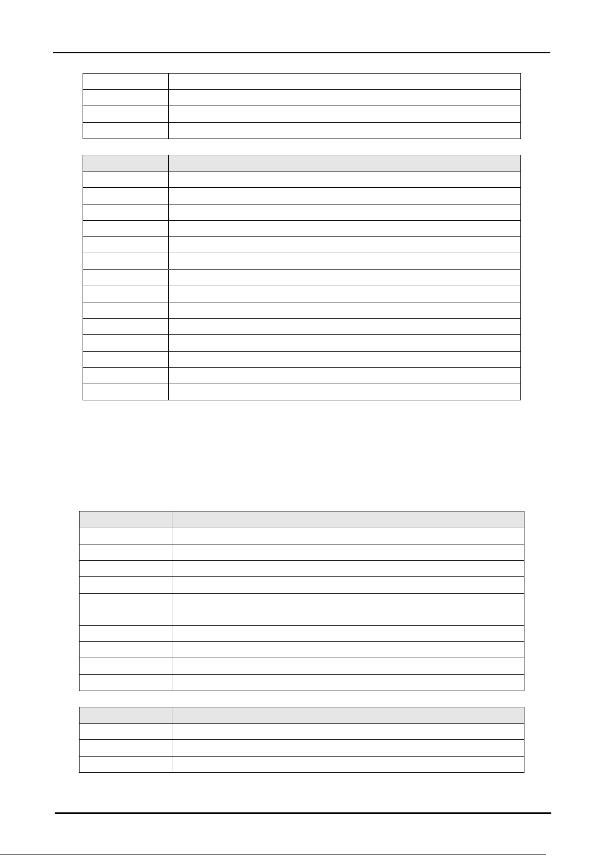
Hypersen Technologies Co., Ltd. HPS-LC010
September 2018 Rev.1.1 52/70
6
CRC high byte
7
CRC low byte
8
0xF5: Message end 1
9
0x5F: Message end 2
Returned data of Read Command:
Byte No.
Description
0
0x5F: Header 1
1
0xF5: Header 2
2
0x00: Message length high byte
3
0x0A: Message length low byte
4
0xB4: RID byte
5
Filter type
6
Filter parameter [31:24]
7
Filter parameter [23:16]
8
Filter parameter [15:8]
9
Filter parameter [7:0]
10
CRC high byte
11
CRC low byte
12
0xF5: Message end 1
13
0x5F: Message end 2
Command #20 Set or Read Controller Sampling Times
This command is used to set the internal sampling times of the controller. The more sampling times, the more
the average number of internal calculation results is, the more stable the data is, but the output rate of the data
will be reduced. This setting is a public setting, and all the program groups share the same setting. The setting
values will be automatically saved to the internal non-volatile memory and reloaded with each power up.
Byte No.
Description
0
0x3F: Header 1
1
0xF3: Header 2
2
0x06: Message length
3
0xB6: Command byte
4
0x0: Read, 0x01: Set. For read command, the following sampling frequency
parameters are not needed.
5
Sampling frequency [15:8]
6
Sampling frequency [7:0]
7
CRC high byte
8
CRC low byte
Returned data of Set Command:
Byte No.
Description
0
0x5F: Header 1
1
0xF5: Header 2
2
0x00: Message length High byte Message
Page 53
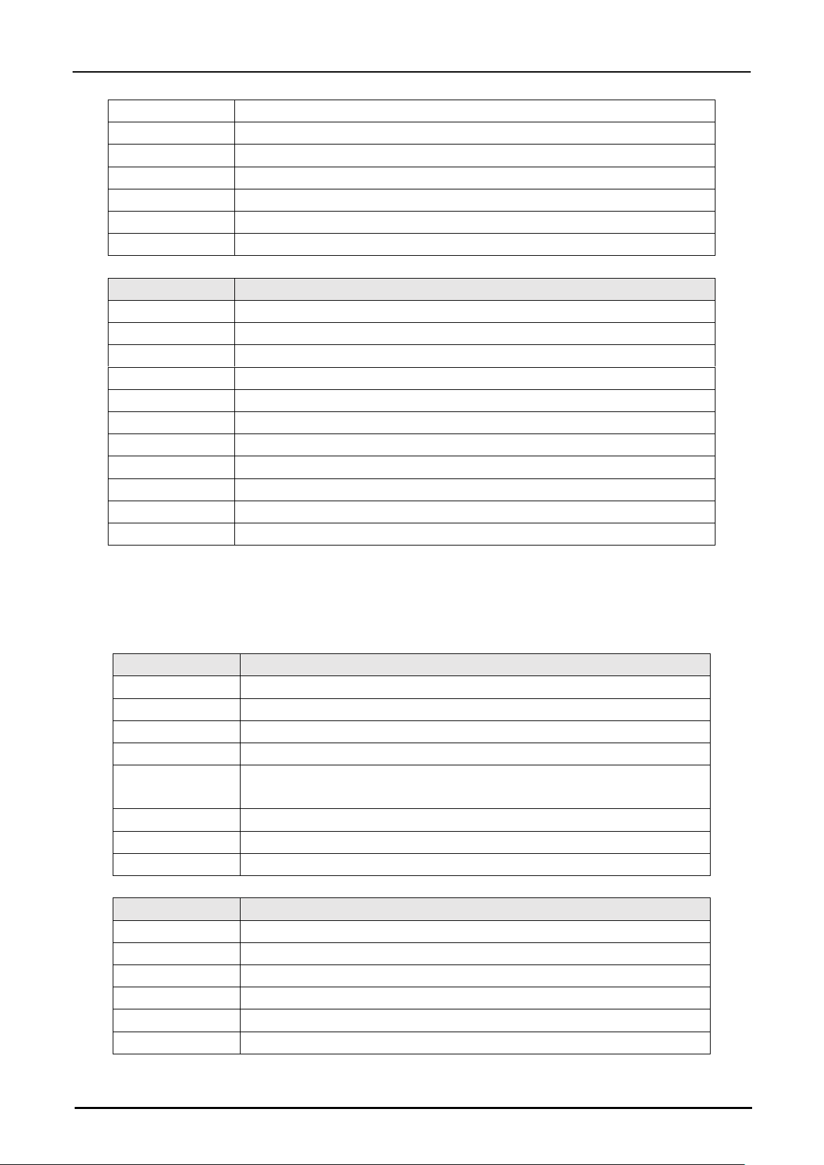
Hypersen Technologies Co., Ltd. HPS-LC010
September 2018 Rev.1.1 53/70
3
0x06: Message length Low byte
4
0xB6: RID byte
5
0x01: Confirmation byte
6
CRC high byte
7
CRC low byte
8
0xF5: Message end 1
9
0x5F: Message end 2
Returned data of Read Command:
Byte No.
Description
0
0x5F: Header 1
1
0xF5: Header 2
2
0x00: Message length high byte
3
0x07: Message length low byte
4
0xB6: RID byte
5
Sampling frequency [15:8]
6
Sampling frequency [7:0]
7
CRC high byte
8
CRC low byte
9
0xF5: Message end 1
10
0x5F: Message end 2
Command#21 Set or read alarm source
This command is used to set or read the alarm source setting value. The setting values will be automatically
saved to the internal non-volatile memory and reloaded with each power up.
Byte No.
Description
0
0x3F: Header 1
1
0xF3: Header 2
2
0x05: Message length
3
0xB7: Command byte
4
0x0: Read, 0x01: Set. For read command, the following warning parameters
are not needed.
5
0x0A: System warning, 0x0B: Overrange warning, 0x0C: all warning
7
CRC high byte
8
CRC low byte
Returned data of Set Command:
Byte No.
Description
0
0x5F: Header1
1
0xF5: Header2
2
0x00: Message length high byte
3
0x06: Message length low byte
4
0xB7: RID byte
5
0x01: Confirmation byte
Page 54
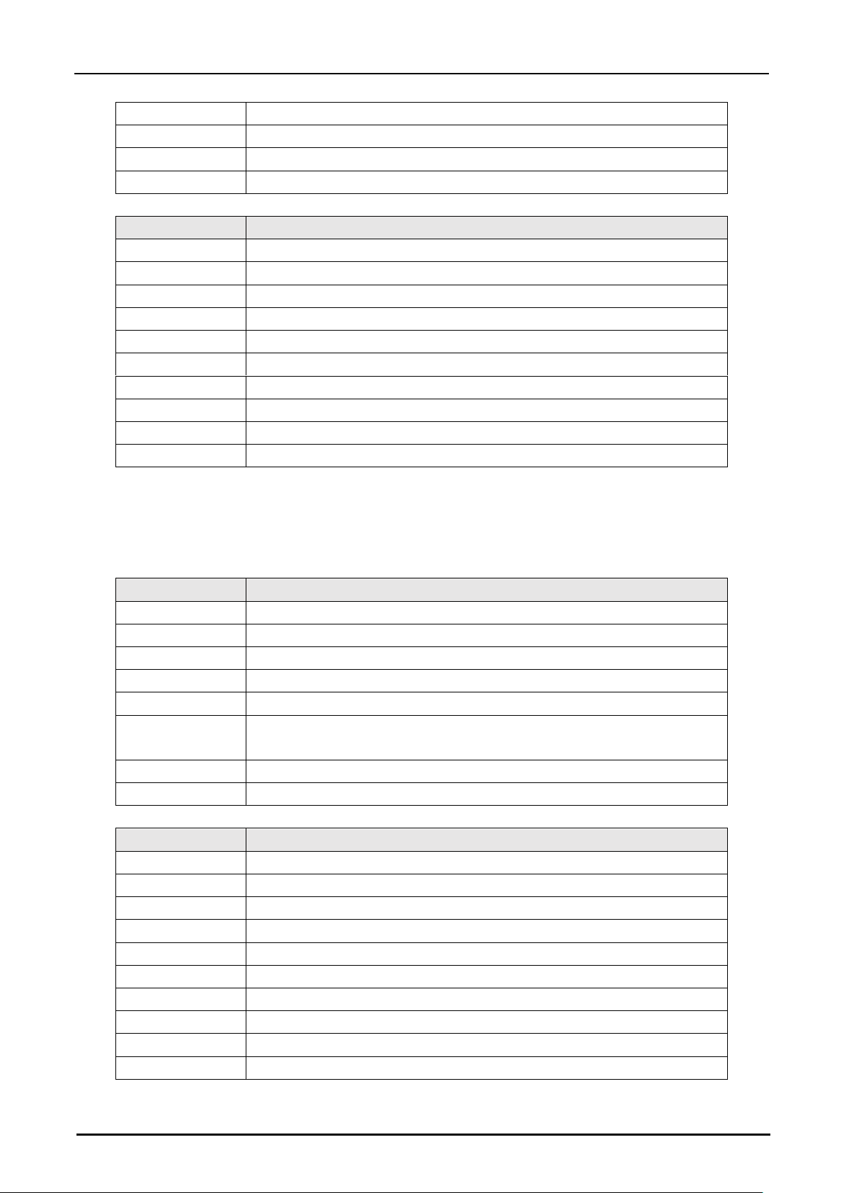
Hypersen Technologies Co., Ltd. HPS-LC010
September 2018 Rev.1.1 54/70
6
CRC high byte
7
CRC low byte
8
0xF5: Message end1
9
0x5F: Message end2
Returned data of Read Command:
Byte No.
Description
0
0x5F: Header 1
1
0xF5: Header 2
2
0x00: Message length high byte
3
0x06: Message length low byte
4
0xB7: RID byte
5
0x0A: System warning, 0x0B: Overrange warning, 0x0C: all warning
6
CRC high byte
7
CRC low byte
8
0xF5: Message end 1
9
0x5F: Message end 2
Command #22 Set or Read Backlight Brightness Value
This command is used to set or read the backlight brightness value of the controller. The setting values will be
automatically saved to the internal non-volatile memory and reloaded with each power up.
Byte No.
Description
0
0x3F: Header 1
1
0xF3: Header 2
2
0x05: Message length
3
0xBA: Command byte
4
0x00: Read, 0x01: Set
5
Backlight brightness value, setting range from 75 to 249. For read
command, this parameter is not needed.
6
CRC high byte
7
CRC low byte
Returned data of Set Command:
Byte No.
Description
0
0x5F: Header 1
1
0xF5: Header 2
2
0x00: Message length high byte
3
0x06: Message length low byte
4
0xBA: RID byte
5
0x01: Confirmation byte
6
CRC high byte
7
CRC low byte
8
0xF5: Message end 1
9
0x5F: Message end 2
Page 55
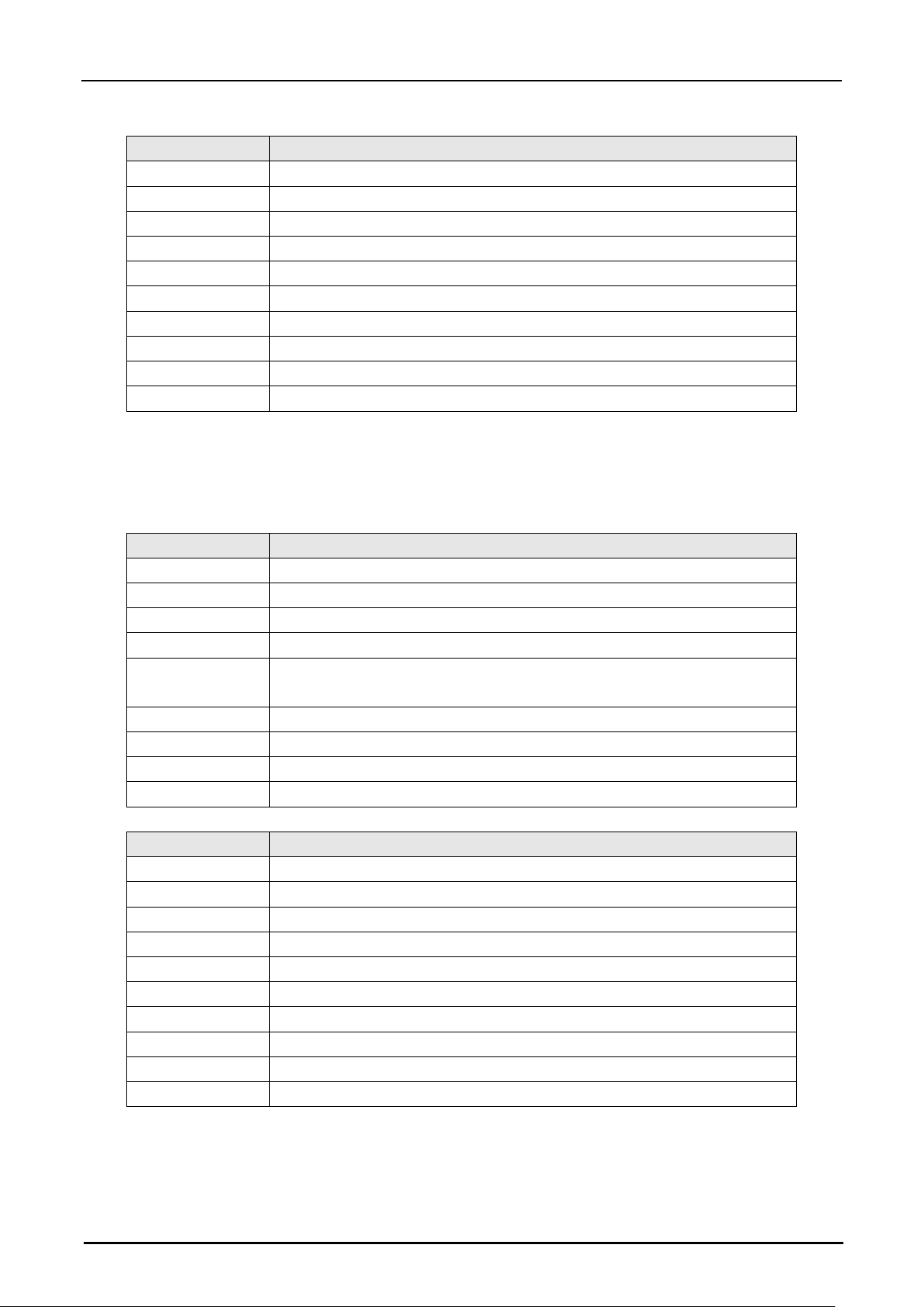
Hypersen Technologies Co., Ltd. HPS-LC010
September 2018 Rev.1.1 55/70
Returned data of Read Command:
Byte No.
Description
0
0x5F: Header 1
1
0xF5: Header 2
2
0x00: Message length high byte
3
0x06: Message length low byte
4
0xBA: RID byte
5
Backlight brightness value [7:0]
6
CRC high byte
7
CRC low byte
8
0xF5: Message end 1
9
0x5F: Message end 2
Command #23 Set or Read Backlight Timeout
This command is used to set or read the controller's backlight timeout (unit: seconds). The setting values will be
automatically saved to the internal non-volatile memory and reloaded with each power up.
Byte No.
Description
0
0x3F: Header 1
1
0xF3: Header 2
2
0x06: Message length
3
0xB8: Command byte
4
0x00: Read, 0x01: Set. For read command, the following timeout time
parameters are not needed.
5
Timeout time [15:8]
6
Timeout time [7:0]
7
CRC high byte
8
CRC low byte
Returned data of Set Command:
Byte No.
Description
0
0x5F: Header 1
1
0xF5: Header 2
2
0x00: Message length high byte
3
0x06: Message length low byte
4
0xB8: RID byte
5
0x01: Confirmation byte
6
CRC high byte
7
CRC low byte
8
0xF5: Message end 1
9
0x5F: Message end 2
Page 56
Hypersen Technologies Co., Ltd. HPS-LC010
September 2018 Rev.1.1 56/70
Returned data of Read Command:
Byte No.
Description
0
0x5F: Header 1
1
0xF5: Header 2
2
0x00: Message length high byte
3
0x07: Message length low byte
4
0xB8: RID byte
5
Timeout time [7:0]
6
Timeout time [15:8]
7
CRC high byte
8
CRC low byte
9
0xF5: Message end 1
10
0x5F: Message end 2
Command #24 Set or Read Screen Lock Time
This command is used to set or read the controller's touch screen lock time (unit: seconds). The setting values
will be automatically saved to the internal non-volatile memory and reloaded with each power up.
Byte No.
Description
0
0x3F: Header 1
1
0xF3: Header 2
2
0x06: Message length
3
0xB9: Command byte
4
0x00: Read, 0x01: Set. For read command, the following lock time
parameters are not needed.
5
Lock time [15:8]
6
Lock time [7:0]
7
CRC high byte
8
CRC low byte
Returned data of Set Command:
Byte No.
Description
0
0x5F: Header 1
1
0xF5: Header 2
2
0x00: Message length high byte
3
0x06: Message length low byte
4
0xB9: RID byte
5
0x01: Confirmation byte
6
CRC high byte
7
CRC low byte
8
0xF5: Message end 1
9
0x5F: Message end 2
Page 57
Hypersen Technologies Co., Ltd. HPS-LC010
September 2018 Rev.1.1 57/70
Returned data of Read Command:
Byte No.
Description
0
0x5F: Header 1
1
0xF5: Header 2
2
0x00: Message length high byte
3
0x07: Message length low byte
4
0xB9: RID byte
5
Lock time [7:0]
6
Lock time [15:8]
7
CRC high byte
8
CRC low byte
9
0xF5: Message end 1
10
0x5F: Message end 2
Page 58

Hypersen Technologies Co., Ltd. HPS-LC010
September 2018 Rev.1.1 58/70
CRC16 C language implementation
The CRC16 algorithm used in the command packet and returned data packet is the standard CRC16CCITT, the polynomial coefficient is 0x1021, and the initial value is 0xffff. There are three examples of
CRC16-CCITT implementations:
Implementation1:
#############################################################
#include<stdio.h>
/**
Flash space requirement: low
Calculating speed: slow
*/
/*FunctionName
:
crc_cal_by_bit//CalculateCRCbybit
FunctionParameters
:
unsignedchar*ptr//Pointerofdatabuffer
unsignedcharlen//Lengthofdata
ReturnValue
:
unsignedint
Polynomial: CRC-CCITT0x1021
*/
unsignedintcrc_cal_by_bit (unsignedchar*ptr, unsignedcharlen)
{
#defineCRC_CCITT0x1021
unsignedintcrc=0xffff;
while(len--!=0)
{
for(unsignedchari=0x80;i!=0;i/=2)
{
crc*=2;
if((crc&0x10000)!=0)
crc^=0x11021;
if((*ptr&i)!=0)
crc^=CRC_CCITT;
}
ptr++;
}
returncrc;
}
Page 59

Hypersen Technologies Co., Ltd. HPS-LC010
September 2018 Rev.1.1 59/70
#############################################################
Implementation2:
#############################################################
#include<stdio.h>
/**
Flash space requirement: medium
Calculating speed: medium
*/
/*FunctionName
:
crc_cal_by_halfbyte//CalculateCRCbyhalfbyte
FunctionParameters
:
unsignedchar*ptr//Pointerofdatabuffer
unsignedcharlen//Lengthofdata
ReturnValue
:
unsignedint
Polynomial:CRC-CCITT0x1021
*/
unsignedintcrc_cal_by_halfbyte(unsignedchar*ptr,unsignedcharlen)
{
unsignedshortcrc=0xffff;
while(len--!=0)
{
unsignedcharhigh=(unsignedchar)(crc/4096);
crc<<=4;
crc^=crc_ta_4[high^(*ptr/16)];
high=(unsignedchar)(crc/4096);
crc<<=4;
crc^=crc_ta_4[high^(*ptr&0x0f)];
ptr++;
}
returncrc;
}
unsignedintcrc_ta_4[16]={/*CRChalfbytetable*/
0x0000,0x1021,0x2042,0x3063,0x4084,0x50a5,0x60c6,0x70e7,
0x8108,0x9129,0xa14a,0xb16b,0xc18c,0xd1ad,0xe1ce,0xf1ef,
};
Page 60

Hypersen Technologies Co., Ltd. HPS-LC010
September 2018 Rev.1.1 60/70
#############################################################
Implementation3:
#############################################################
#include<stdio.h>
/**
Flash space requirement: high
Calculating speed: fast
*/
/*FunctionName
:
crc_cal_by_byte//CalculateCRCbyhalfbyte
FunctionParameters
:
unsignedchar*ptr//Pointerofdatabuffer
unsignedcharlen//Lengthofdata
ReturnValue
:
unsignedint
Polynomial: CRC-CCITT0x1021
*/
unsignedintcrc_ta_8[256] = {/*CRCbytetable*/
0x0000,0x1021,0x2042,0x3063,0x4084,0x50a5,0x60c6,0x70e7,
0x8108,0x9129,0xa14a,0xb16b,0xc18c,0xd1ad,0xe1ce,0xf1ef,
0x1231,0x0210,0x3273,0x2252,0x52b5,0x4294,0x72f7,0x62d6,
0x9339,0x8318,0xb37b,0xa35a,0xd3bd,0xc39c,0xf3ff,0xe3de,
0x2462,0x3443,0x0420,0x1401,0x64e6,0x74c7,0x44a4,0x5485,
0xa56a,0xb54b,0x8528,0x9509,0xe5ee,0xf5cf,0xc5ac,0xd58d,
0x3653,0x2672,0x1611,0x0630,0x76d7,0x66f6,0x5695,0x46b4,
0xb75b,0xa77a,0x9719,0x8738,0xf7df,0xe7fe,0xd79d,0xc7bc,
0x48c4,0x58e5,0x6886,0x78a7,0x0840,0x1861,0x2802,0x3823,
0xc9cc,0xd9ed,0xe98e,0xf9af,0x8948,0x9969,0xa90a,0xb92b,
0x5af5,0x4ad4,0x7ab7,0x6a96,0x1a71,0x0a50,0x3a33,0x2a12,
0xdbfd,0xcbdc,0xfbbf,0xeb9e,0x9b79,0x8b58,0xbb3b,0xab1a,
0x6ca6,0x7c87,0x4ce4,0x5cc5,0x2c22,0x3c03,0x0c60,0x1c41,
0xedae,0xfd8f,0xcdec,0xddcd,0xad2a,0xbd0b,0x8d68,0x9d49,
0x7e97,0x6eb6,0x5ed5,0x4ef4,0x3e13,0x2e32,0x1e51,0x0e70,
0xff9f,0xefbe,0xdfdd,0xcffc,0xbf1b,0xaf3a,0x9f59,0x8f78,
0x9188,0x81a9,0xb1ca,0xa1eb,0xd10c,0xc12d,0xf14e,0xe16f,
0x1080,0x00a1,0x30c2,0x20e3,0x5004,0x4025,0x7046,0x6067,
0x83b9,0x9398,0xa3fb,0xb3da,0xc33d,0xd31c,0xe37f,0xf35e,
0x02b1,0x1290,0x22f3,0x32d2,0x4235,0x5214,0x6277,0x7256,
0xb5ea,0xa5cb,0x95a8,0x8589,0xf56e,0xe54f,0xd52c,0xc50d,
0x34e2,0x24c3,0x14a0,0x0481,0x7466,0x6447,0x5424,0x4405,
0xa7db,0xb7fa,0x8799,0x97b8,0xe75f,0xf77e,0xc71d,0xd73c,
0x26d3,0x36f2,0x0691,0x16b0,0x6657,0x7676,0x4615,0x5634,
0xd94c,0xc96d,0xf90e,0xe92f,0x99c8,0x89e9,0xb98a,0xa9ab,
0x5844,0x4865,0x7806,0x6827,0x18c0,0x08e1,0x3882,0x28a3,
Page 61

Hypersen Technologies Co., Ltd. HPS-LC010
September 2018 Rev.1.1 61/70
0xcb7d,0xdb5c,0xeb3f,0xfb1e,0x8bf9,0x9bd8,0xabbb,0xbb9a,
0x4a75,0x5a54,0x6a37,0x7a16,0x0af1,0x1ad0,0x2ab3,0x3a92,
0xfd2e,0xed0f,0xdd6c,0xcd4d,0xbdaa,0xad8b,0x9de8,0x8dc9,
0x7c26,0x6c07,0x5c64,0x4c45,0x3ca2,0x2c83,0x1ce0,0x0cc1,
0xef1f,0xff3e,0xcf5d,0xdf7c,0xaf9b,0xbfba,0x8fd9,0x9ff8,
0x6e17,0x7e36,0x4e55,0x5e74,0x2e93,0x3eb2,0x0ed1,0x1ef0
};
unsignedintcrc_cal_by_byte (unsignedchar*ptr, unsignedcharlen)
{
unsignedshortcrc=0xffff;
while (len--! =0)
{
unsignedinthigh=(unsignedint)(crc/256);
crc<<=8;
crc^=crc_ta_8[high^*ptr];
ptr++;
}
returncrc;
}
#############################################################
TestingCode:
#############################################################
voidmain ()
{
unsignedcharsample_data[]={0x01,0x01,0x01,0x06,0xd9,0xfc,0x8c,0x02,0x01,0x00,0x01};//Resultshould
be:0x9b94
unsignedchardata1[]={0x63};//Resultshouldbe:0xbd35
unsignedchardata2[]={0x8c};//Resultshouldbe:0xb1f4
unsignedchardata3[]={0x7d};//Resultshouldbe:0x4eca
unsignedchardata4[]={0xaa,0xbb,0xcc};//Resultshouldbe:0x6cf6
unsignedchardata5[]={0x00,0x00,0xaa,0xbb,0xcc};//Resultshouldbe:0xb166
unsignedshortr1=0,r2=0,r3=0,r4=0,r5=0,r_sample_data;
//Implementation1
r1=crc_cal_by_byte(data1,1);
r2=crc_cal_by_byte(data2,1);
r3=crc_cal_by_byte(data3,1);
r4=crc_cal_by_byte(data4,3);
r5=crc_cal_by_byte(data5,5);
r_sample_data=crc_cal_by_byte(sample_data,11);
printf("Implementation_1:r1=%x,r2=%x,r3=%x,r4=%x,r5=%x,r_sample_data=%x\n",r1,r2,r3,r4,r5,r_sampl
Page 62

Hypersen Technologies Co., Ltd. HPS-LC010
September 2018 Rev.1.1 62/70
e_data);
r1=r2=r3=r4=r5=0;
//Implementation2
r1=crc_cal_by_bit(data1,1);
r2=crc_cal_by_bit(data2,1);
r3=crc_cal_by_bit(data3,1);
r4=crc_cal_by_bit(data4,3);
r5=crc_cal_by_bit(data5,5);
r_sample_data=crc_cal_by_bit(sample_data,11);
printf("Implementation_2:r1=%x,r2=%x,r3=%x,r4=%x,r5=%x,r_sample_data=%x\n",r1,r2,r3,r4,r5,r_sampl
e_data);
r1=r2=r3=r4=r5=0;
//Implementation3
r1=crc_cal_by_halfbyte(data1,1);
r2=crc_cal_by_halfbyte(data2,1);
r3=crc_cal_by_halfbyte(data3,1);
r4=crc_cal_by_halfbyte(data4,3);
r5=crc_cal_by_halfbyte(data5,5);
r_sample_data=crc_cal_by_halfbyte(sample_data,11);
printf("Implementation_3:r1=%x,r2=%x,r3=%x,r4=%x,r5=%x,r_sample_data=%x\n",r1,r2,r3,r4,r5,r_sampl
e_data);
r1=r2=r3=r4=r5=0;
}
#############################################################
Page 63
Hypersen Technologies Co., Ltd. HPS-LC010
September 2018 Rev.1.1 63/70
Chapter 6 Specification
Specification
Controller
Model Type
HPS-LC010
Power supply
Power voltage
DC 12V~26V, typical DC24V
Maximum current
1A
Number of sensor heads suppotred
1
Power consumption
5W (Typical)
Working temperature
0~50
℃
Relative humidity
35 to 85%RH (No condensation)
Weight
*1
270g
Communication
interfaces
USB-S x 1
USB 2.0 High-speed
RS-232C x 1
Baud rate: 9600 to 115200bps
Data length: 8 bits
Stop bit length: 1 bit
Parity: No/Even/Odd
LAN x 1
100 Mbps
Display
Screen
4.3-inch Touch screen
Minimum display unit
0.1µm
Display range
±10mm
Refresh period
5 times / s
LED indicator
Power and measurement status
I/O port
Auto-zero input
Non-voltage input
Cancel activate auto-zero
input
Clock Synchronous input
Laser control input
Normal comparator output
NPN open-collector output
*2
, (Max. 80V, 1A)
Warning output
*1 Not include cable
*2 Can be adjusted according to the actual needs of customers
Page 64
Hypersen Technologies Co., Ltd. HPS-LC010
September 2018 Rev.1.1 64/70
Sensor head
Model
HPS-LC010
Reference distance
55mm±0.5mm
Measuring range
±10mm
Install mode
Diffuse reflection, mirror reflection
Light source
Wavelength: 655nm
Laser power: <0.48mW.
Laser classification: Class II
Laser beam diameter
Ø30µm (At reference distance)
Linearity
*1
Full scale ±0.025% (F.S.=20mm)
Repeatability
*2
0.1µm (RMS)
Sampling period
Auto adjust, typical value 125us
Temperature fluctuation
Full scale 0.015%/
℃
(F.S.=20mm)
Environmental
tolerance
Enclosure
rating
IP67
Ambient light
Incandescent or fluorescent: up to 10000lx
Ambient
temperature
*3
0 to +50°C
Relative
humidity
35% to 85% RH (No Condensation)
Vibration
In X, Y, Z directions, 10 to 55Hz, 1.5 double amplitude, 2 hours
in all directions
Material
Aluminum 6061
Sensor head to controller cable
length
1.5m
Weight (include cable)
about 390g
*1 This value is obtained by measuring a standard target in the normal measurement mode.
*2 Set the average number of measurements to 16384 and obtain this value by measuring the standard target at the reference distance.
*3 If the ambient temperature is higher than 40°C, it must be installed on a metal plate.
Boot time after power on
Boot time after turning on the power of the controller: about 10 seconds.
Page 65
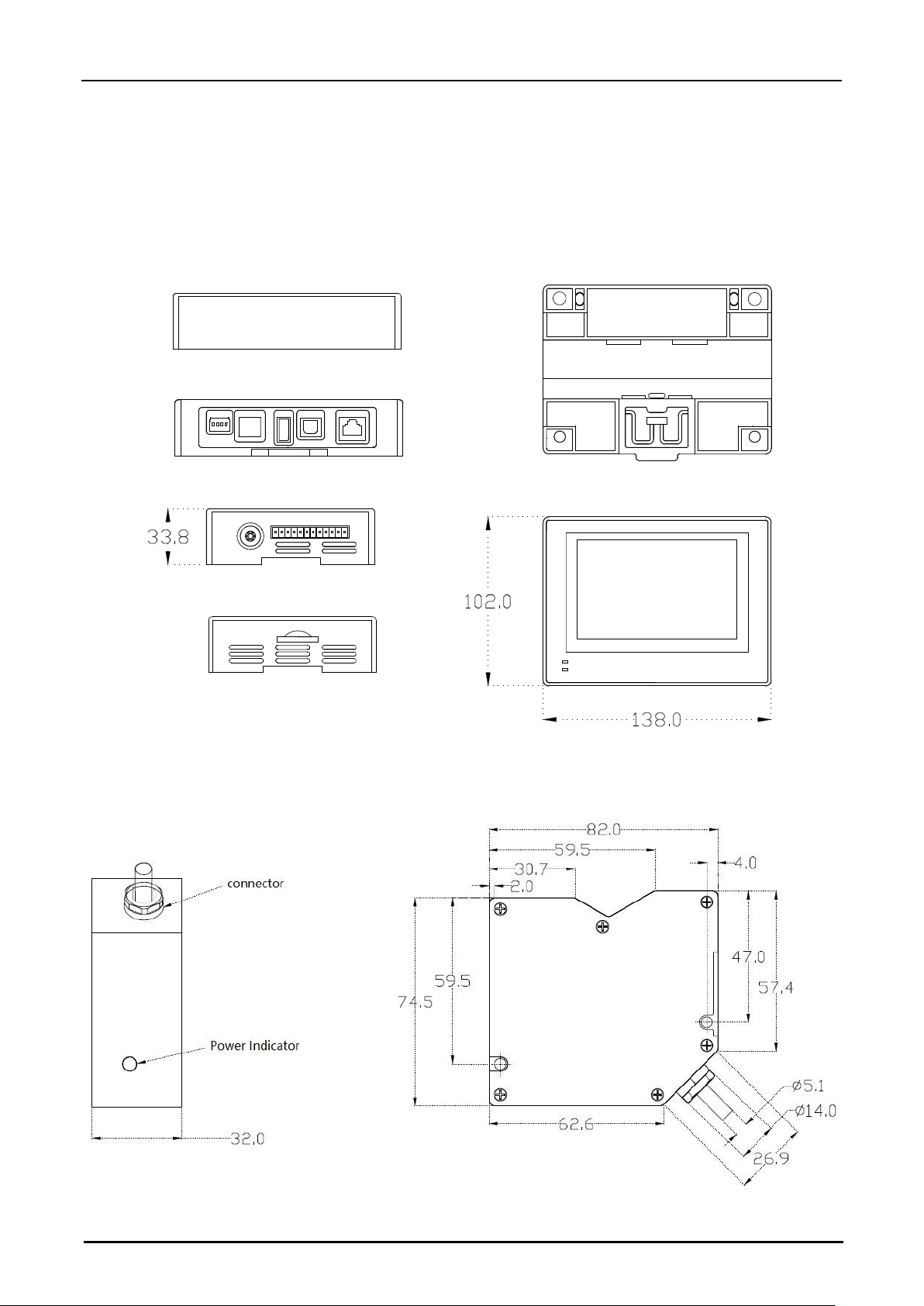
Hypersen Technologies Co., Ltd. HPS-LC010
September 2018 Rev.1.1 65/70
Dimension
HPS-LC010 controller
HPS-LC010 controller dimension drawings (unit: mm)
HPS-LC010 sensor head
(unit: mm)
Page 66
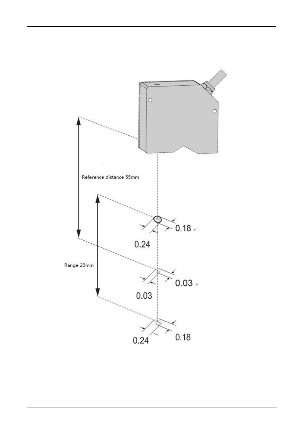
Hypersen Technologies Co., Ltd. HPS-LC010
September 2018 Rev.1.1 66/70
Beam diameter <unit: mm>
If the interfering object is outside the range of the spot, it does not affect the detection.
Page 67
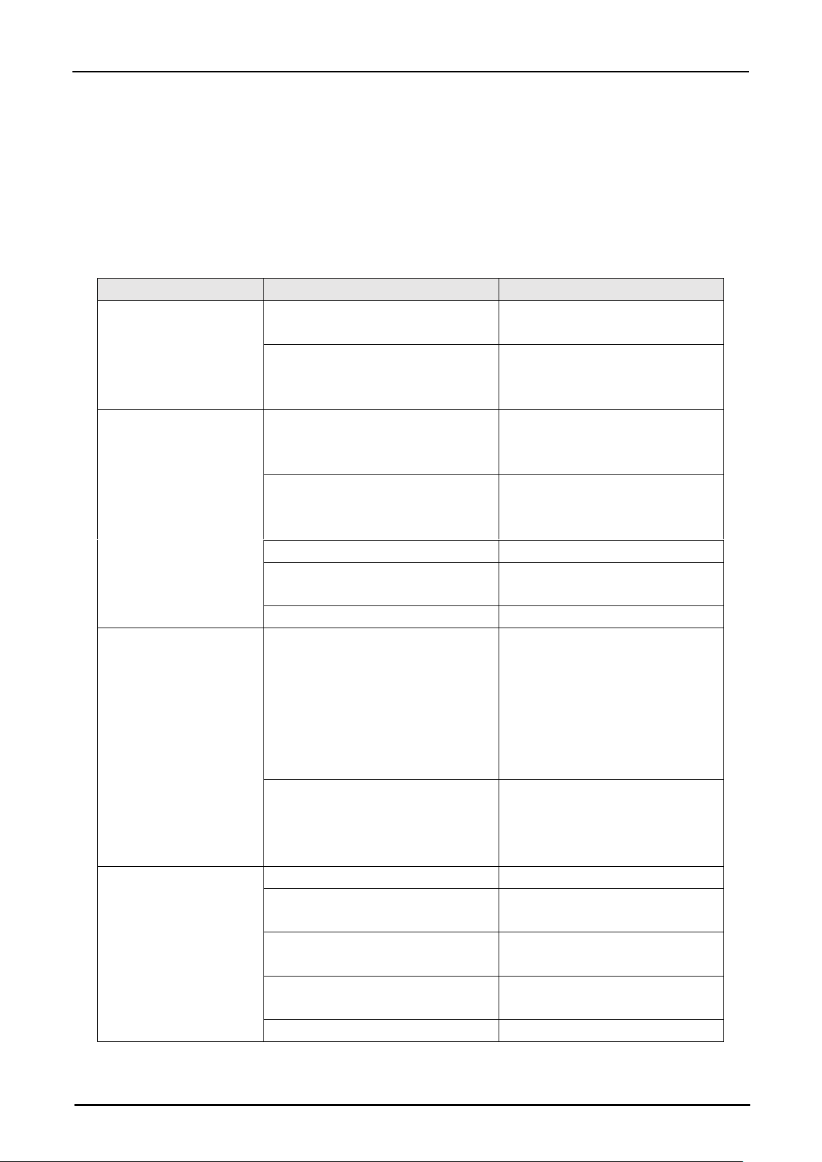
Hypersen Technologies Co., Ltd. HPS-LC010
September 2018 Rev.1.1 67/70
Appendix
Troubleshooting
This section provides countermeasures for errors or problems that may occur during the operation of the HPS-
LC010.
Problem
Probable reason
Countermeasure
Nothing appears on the
display
Is the power line properly
connected?
Correctly connect power cable
Is the supply voltage or current in
compliance with the specification?
Make sure the supply voltage and
current values are within the
required range.
Do not display measured
values
Is the measurement target within the
measurement range?
Place the measurement target
correctly within the measurement
range.
Is the synchronization control
correctly set according to the
measurement mode?
Adjust to the correct setting.
Is the glass cover dirty?
Clean dust and dirt
Does the glass cover have flaws or
cracks?
Must replace glass cover, please
contact the original factory
Is there condensation in the device?
Check install environment
Does not emit laser
beam
Is the cable connection from the
sensor head to the controller
correct?
Is the power cable connected
correctly?
Is the supply voltage and current in
compliance with the specifications?
Check if the sensor head LED
status light is flashing or steady. If
it is flashing or steady, the
connection is normal. Otherwise,
check if the power supply voltage
and current is in compliance with
the requirements.
Is there a IN terminal configured for
the LaserCtrl function, and is the
level polarity setting suitable for the
input level?
If the IN terminal is configured as
LaserCtrl and active low, the laser
will be turned off if the input level is
high.
Measured value show
fluctuations
Is the glass cover dirty?
Clean dust and dirt
Does the glass cover have flaws or
cracks?
Must replace glass cover, please
contact original factory.
Is there liquid or splash in the work
environment?
Use an air purifier or other method
to remove splashes
If there are multiple sensors, do they
interfere with each other?
Please avoid installation methods
that interfere with each other.
Is there a strong ambient light?
Prevent exposure to ambient light.
Page 68
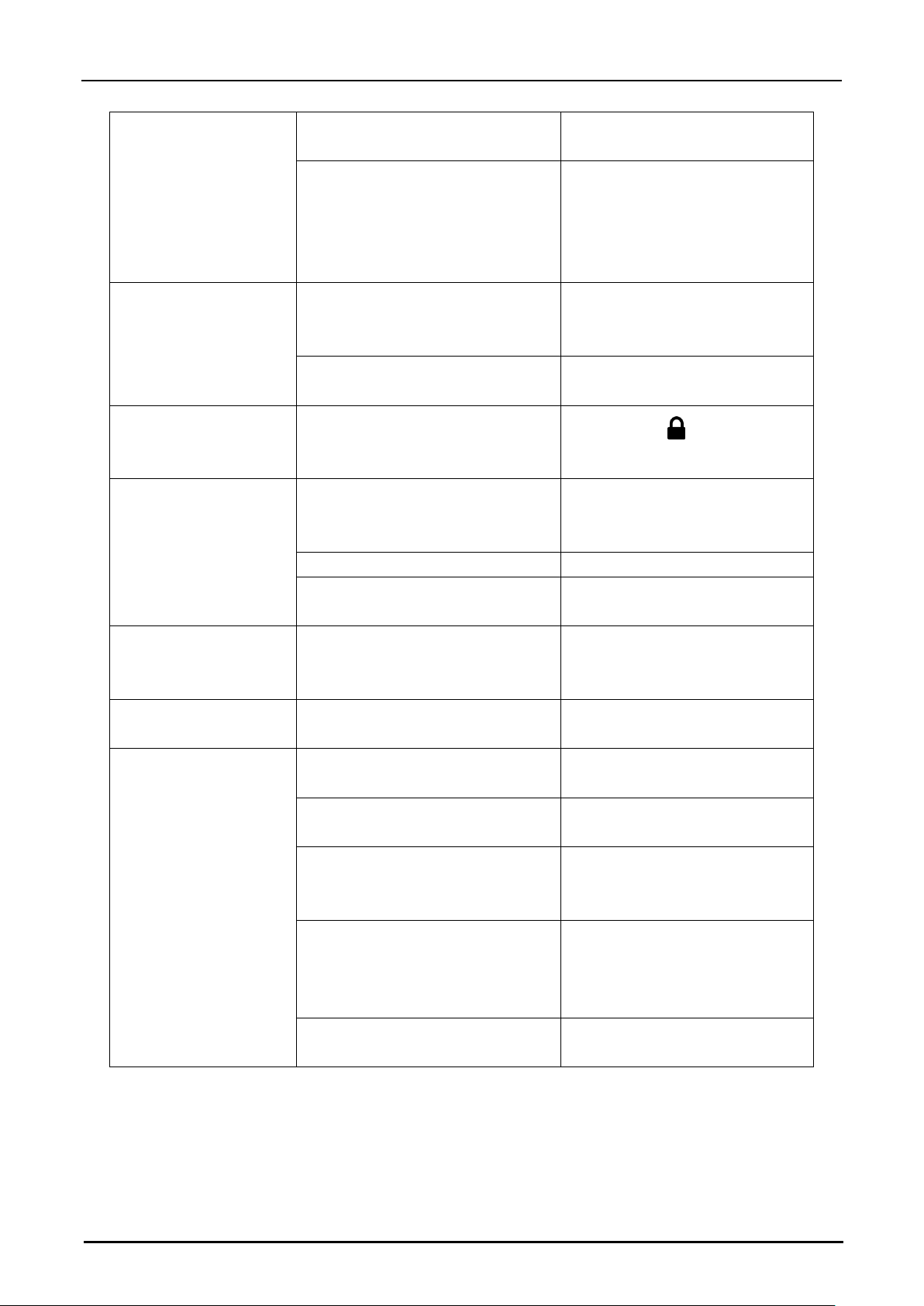
Hypersen Technologies Co., Ltd. HPS-LC010
September 2018 Rev.1.1 68/70
Is the measurement target or sensor
head vibrating?
Take appropriate measures such
as vibration isolation
Is the peak -peak hold measurement
mode enabled?
The peak-peak hold mode outputs
the maximum and minimum values
for the specified time period at the
same time, so fluctuations occur,
which is normal.
The measured value
shows a deviation
Is the measurement target tilted or
displaced?
Place the measurement target
correctly within the measurement
range.
Will the temperature in the working
environment change drastically?
Keep the ambient temperature
constant
Controller touch screen
operation button is
invalid.
Is the screen locked?
Please Press to unlock
Comparator output is
abnormal.
Is the cabling correct?
Check the output circuit and wiring
and make sure the connection is
correct
Is the tolerance setting correct?
Reset the tolerance
Is the output polarity of the
comparator correct?
Adjust to correct settings
LAN can not
communicate
Check that the IP address, subnet
mask, and port number are set
correctly?
Adjust to correct settings
USB can not
communicate
Check if the USB driver is installed
correctly?
Refer to the LC010 Client Software
Operating Instructions.
RS-232C can not
communicate
Is the communication cable
connected correctly?
Connect communication cable
correctly.
Is the communication cable connect
in compliance of the specification?
Check connection of
communication cable
Is the communication parameters
set correctly?
Set the same communication
parameters between the LC-010
series and external devices.
Is the communication command
format correct and is the CRC check
code calculated correctly?
Refer to the command section to
check if the format requirements
are met and check if the CRC
check is correct.
Does the controller have the UART
communication interface enabled?
Enable UART communication port
Page 69
Hypersen Technologies Co., Ltd. HPS-LC010
September 2018 Rev.1.1 69/70
Option list
The following table lists the HPS-LC010 supported options
Name
Type
Application
RS-232C cable
CB-RS232E
Communication cable for RS-232C (2.5m)
USB cable
CB-USB
USB connection cable (2m)
Ethernet cable
CB-LAN
Ethernet communication crossover cable (3m)
Sensor head extension
cable
CB-A20E
Sensor head to controller extension cable (2m)
CB-A35E
Sensor head to controller extension cable
(3.5m)
Revision history
Date
Version
Description
2018/04/08
1.0
Initial version.
2018/09/26
1.1
Corrected some spelling mistakes.
Page 70

Hypersen Technologies Co., Ltd. HPS-LC010
September 2018 Rev.1.1 70/70
Product warranty policy
This product has undergone strict factory inspection. If there is any malfunction, please contact the factory and
provide demessage ends of the fault.
1.
Warranty period
The warranty period is one year from the date the purchaser receives the product.
2. Warranty range
(1) If there is a natural failure during the warranty period, we will repair the product free of charge. However,
the following conditions are not covered by the warranty.
• Failure to follow the operating manual, the user manual, or the conditions specified in the technical
requirements specified by the purchaser and our company, incorrect operation in the environment, or
malfunction caused by improper use.
• The failure is not caused by a product defect, but by the purchaser's equipment or the purchaser's software
design.
• Failures caused by modifications or repairs by non-original employee.
• Properly repair or replace consumables in accordance with the operation manual or user manual.
• Failures caused by unforeseen changes in the level of science and technology after the product is shipped.
• We are not responsible for warranty due to natural disasters such as fires, earthquakes and floods, or external
factors such as abnormal voltage.
(2) We are not responsible for any indirect loss (equipment damage, loss of opportunity, loss of profits, etc.) or
other losses caused by our purchaser.
3. Product suitability
This product is designed and manufactured for general purpose products in the general industry. Therefore, our
products should not be used for the following applications and are not suitable for their use. If the purchaser is
responsible for their own, they will consult with us on the use of the products and understand the technical
specifications, grades and performance of the products, and take necessary the safety measures are then
available for the product. In this case, the product warranty coverage is the same as above.
• Facilities that have a serious impact on life and property, such as nuclear power plants, airports, railways, ships,
motorized equipment and medical equipment
• Public utilities such as electricity, gas and water services
• Outdoor use of similar conditions or environment
4. Contact
Hypersen Technologies (Shenzhen) Co., Ltd.
A425, Baoan Intelligence Valley, No.4 Yintian Rd., Xixiang Street, Baoan Dist., Shenzhen City, Guangdong
Province, China
Postcode: 518100
Tel: +86-755-82591285 Fax: +86-755-82591681
http://www.hypersen.com
 Loading...