


Hypermedia HG-7000
Product Manual
3U and 6U SMS Pro Gateways
Release 5.5 (March 2015)

Hypermedia Systems
Hypermedia Systems Ltd.
2b, Professor Bergman St., Rabin Science Park,
Rehovot, 7670504, Israel
Telephone: (+972)-77-4445050
Fax: (+972)-8-936-3066
For general inquiries: info@hyperms.com
For sales inquiries: sales@hyperms.com
For Technical Support: support@hyperms.com
Web site: http://www.hyperms.com/
PROPRIETARY AND CONFIDENTIAL
Copyright © 2013 by Hypermedia Systems Ltd. All rights reserved.
No part of this document may be reproduced, transmitted or copied in any form or by
any means- graphic, electronic, or mechanical, including photocopying, typing or
information retrieval systems- without the express written permission of Hypermedia
Systems Ltd.
Hypermedia Systems Ltd.
ii

Hypermedia Systems
Release 5.5 (March 2015)
iii

Hypermedia Systems
Hypermedia Systems Ltd. LICENSE AGREEMENT AND WARRANTY
IMPORTANT — READ CAREFULLY
This Hypermedia Systems Ltd. License Agreement (the "AGREEMENT") is a legal agreement between you
(either an individual or a single entity) and Hypermedia Systems Ltd. for the product accompanying this
AGREEMENT. The product includes computer software, associated media and printed materials, and may
include "online" or electronic documentation (the "SOFTWARE"). The PRODUCT may also include hardware (the
―HARDWARE‖). The SOFTWARE and the HARDWARE are referred to, collectively, as the PRODUCT.
BY INSTALLING AND/OR USING THE PRODUCT YOU AGREE TO BE BOUND BY THE TERMS OF THIS
AGREEMENT.
IF YOU DO NOT AGREE TO THE TERMS OF THIS AGREEMENT, PROMPTLY ERASE ALL COPIES OF THE
SOFTWARE IN YOUR POSSESSION, AND RETURN THE SOFTWARE AND ANY ACCOMPANYING
HARDWARE TO THE PLACE FROM WHICH YOU OBTAINED IT.
COPYRIGHT
All title and copyrights in and to the PRODUCT are owned by Hypermedia Systems Ltd. The PRODUCT is
protected by copyright laws and international copyright treaties, as well as other intellectual property laws and
treaties.
GRANT OF LICENSE FOR THE SOFTWARE
The SOFTWARE is licensed, not sold. Hypermedia Systems Ltd. grants to you a non-exclusive, non-transferable,
royalty-free right to install and use the SOFTWARE, provided that the SOFTWARE will be used by a single
person on a single computer and for personal non-commercial, internal use only. If accompanied by a proof-ofpurchase document specifying "site license," "company license," or any other multiple-user type license scheme,
then the terms of that document shall override this single-user restriction. Any rights not expressly granted herein
are retained by Hypermedia Systems Ltd.
OTHER RESTRICTIONS
This AGREEMENT is your proof of license to exercise the rights granted herein and must be retained by you.
You may not rent, lease, reverse engineer, decompile, modify, or disassemble the PRODUCT, or create
derivative works based on the PRODUCT.
LIMITED HARDWARE WARRANTY
The HARDWARE is protected against defects in material and workmanship, under normal use, for one (1) year
from the original purchase date.
If the HARDWARE fails to perform within the abovementioned warranty period, you must return the PRODUCT to
Hypermedia Systems Ltd. and prepay any shipping charges, export taxes, custom duties and taxes, or any
charges associated with transportation of the Product. In addition, you are responsible for insuring the PRODUCT
shipped or returned and assume the risk of loss during shipment.
All returned PRODUCTS must be accompanied by a description of the problem, a proof of the place and date of
purchase, and the original shipping and packing materials.
Hypermedia Systems Ltd. shall, at its sole discretion, either repair the PRODUCT or replace it with a product of
the same functionally. Replacement products may be refurbished or contain refurbished materials. If Hypermedia
Systems Ltd. cannot repair or replace the PRODUCT, Hypermedia Systems Ltd. will refund the depreciated
purchase price of the PRODUCT.
This limited warranty does not apply to any PRODUCT not purchased from Hypermedia Systems Ltd., or from a
Hypermedia Systems Ltd. authorized reseller, or on which the serial number has been removed or defaced. This
limited warranty also does not cover any PRODUCT that has been damaged or rendered defective as a result of
(a) improper transportation or packing when returning the PRODUCT to Hypermedia Systems Ltd.; (b) use of the
PRODUCT other than in accordance with its instructions, or other misuse or abuse of the PRODUCT; (c)
modification of the PRODUCT; (d) service by anyone other than a Hypermedia Systems Ltd.-approved agent; (e)
unusual physical or electrical stress or interference, failure or fluctuation of electrical power, lightning, static
electricity, improper temperature or humidity, fire, or acts of God.
The maximum liability of Hypermedia Systems Ltd. under this limited warranty is limited to the purchase price of
the PRODUCT covered by the warranty.
Hypermedia Systems Ltd.
iv

Hypermedia Systems
Hypermedia Systems Ltd. reserves the right to refuse PRODUCTS (i) that are not covered by the warranty; or (ii)
for which there is no problem found. Such PRODUCTS shall be returned to the purchaser at purchaser’s
expense.
DISCLAIMER
EXCEPT AS EXPRESSLY STATED ABOVE OR AS REQUIRED BY LAW, Hypermedia Systems Ltd.
DISCLAIMS ANY WARRANTY FOR THE PRODUCT. THE PRODUCT IS PROVIDED "AS IS" WITHOUT
REPRESENTATION OR WARRANTY OF ANY KIND, EITHER EXPRESS OR IMPLIED, INCLUDING,
WITHOUT LIMITATION, THE IMPLIED WARRANTIES OF MERCHANTABILITY, FITNESS FOR A
PARTICULAR PURPOSE, OR NONINFRINGEMENT. Hypermedia Systems Ltd. ASSUMES NO RISK ARISING
OUT OF THE USE OR PERFORMANCE OF THE PRODUCT.
NO LIABILITY FOR CONSEQUENTIAL DAMAGES
IN NO EVENT SHALL Hypermedia Systems Ltd., ITS AGENTS OR ITS SUPPLIERS BE LIABLE FOR ANY
DAMAGES WHATSOEVER (INCLUDING, WITHOUT LIMITATION, DIRECT, INDIRECT, SPECIAL OR OTHER
CONSEQUENTIAL OR INCIDENTAL DAMAGES; DAMAGES FOR LOSS OF BUSINESS PROFITS, BUSINESS
INTERRUPTION, LOSS OF BUSINESS INFORMATION, OR ANY OTHER PECUNIARY LOSS) ARISING
DIRECTLY OR INDIRECTLY OUT OF THE USE OF OR INABILITY TO USE THE PRODUCT, EVEN IF
Hypermedia Systems Ltd. HAS BEEN ADVISED IN ADVANCE OF THE POSSIBILITY OF SUCH DAMAGES.
Because some states or jurisdictions do not allow the exclusion or limitation of liability for consequential or
incidental damages, the above limitation may not apply to you.
U.S. GOVERNMENT RESTRICTED RIGHTS
For purchases made in the United States: The SOFTWARE and any accompanying documentation are provided
with restricted rights. Use, duplication or disclosure by the Government is subject to restrictions as set forth in
subparagraph (b) (3) and (c) (1) (ii) of The Rights in Technical Data and Computer Software clause at DFARS
252.227-7013 or subparagraphs (c) (1) and (2) of the Commercial Computer Software-Restricted Rights at 48
CFR 52.227-19, as applicable.
AMENDMENTS
Hypermedia Systems Ltd. may amend these terms and conditions at any time by posting a notice on one or more
of its websites. Your continued use of the PRODUCT shall constitute your acceptance of such amended terms.
Accordingly, we urge you to visit our websites periodically to review the current and effective terms and
conditions for use of our products. Certain provisions of these terms and conditions may be superseded by
expressly designated legal notices or terms outlined on our websites.
GOVERNING LAW
This AGREEMENT and any and all claims relating to the PRODUCT shall be governed by the laws of the State
of Israel, without regard to or application of choice of law or principles, and the courts of Tel-Aviv Jaffa shall have
sole and exclusive jurisdiction over any dispute arising in connection with this Agreement and/or the use of the
PRODUCT.
NO WAIVER
No delay or failure to take action under these terms and conditions will constitute a waiver by Hypermedia
Systems Ltd. unless expressly waived in writing by a duly authorized officer of Hypermedia Systems Ltd.
Release 5.5 (March 2015)
v

Hypermedia Systems
Hardware and Installation
Table of Contents
Before You Begin .......................................................... 1
1 Hardware and Installation ...................................... 2
1.1 Overview .................................................................................... 3
1.1.1 Package Contents ......................................................................................... 3
1.2 Safety Information ..................................................................... 4
1.3 System Components ................................................................. 5
1.4 Typical Board Configurations ................................................... 6
1.4.1 3U Series ...................................................................................................... 6
1.4.2 6U Series ...................................................................................................... 7
1.5 Pre-Installation Preparations .................................................... 8
1.6 Cable Connections .................................................................... 9
1.6.1 Standard Gateway - Hybrid Based (HBN) ..................................................... 9
1.6.2 Heavy-Duty Gateway – PC Based .............................................................. 10
1.7 Inserting the SIM Cards ........................................................... 11
1.7.1 Inserting the SD Card (Standard Gateway) ................................................. 12
1.8 Powering Up and LEDs Status ................................................ 13
1.8.1 Powering Up................................................................................................ 13
1.8.2 LEDs Status ................................................................................................ 13
2 HMC Quick Start ................................................... 18
2.1 Installation ................................................................................ 19
2.2 Setting the IP Address ............................................................ 21
2.3 Start-up and Initial Connecting ............................................... 23
2.4 Save and Backup/Restore Configuration Settings ................ 26
2.4.1 Save All ....................................................................................................... 26
2.4.2 Store Settings on Cards .............................................................................. 26
2.4.3 Backup/Restore ........................................................................................... 26
Hypermedia Systems Ltd.
vi

Hypermedia Systems
Hardware and Installation
3 Configuring a Cellular Card ................................. 27
3.1 Cellular Card and System Terminology ................................. 28
3.2 Media Connections .................................................................. 29
3.2.1 Associating/Linking Cellular Channels ........................................................ 29
3.2.2 Auto Linking ................................................................................................ 30
3.2.3 Unlinking Cellular Allocations ...................................................................... 31
3.3 PIN Codes ................................................................................. 32
3.4 Reset ......................................................................................... 33
3.5 Information Screens ................................................................ 35
3.5.1 Module Info ................................................................................................. 35
3.5.2 Serial Numbers ........................................................................................... 35
3.6 Locks ........................................................................................ 37
3.7 SIM Select................................................................................. 38
3.8 Cell Selection ........................................................................... 40
3.9 Settings .................................................................................... 42
3.10 Network Parameters ................................................................ 43
3.11 USSD SIM Balance ................................................................... 44
3.12 Monitoring Cellular Cards ....................................................... 45
3.12.1 All Cells ....................................................................................................... 45
3.12.2 Reception .................................................................................................... 46
3.12.3 Status .......................................................................................................... 46
4 Configuring the SMS Server ................................ 48
4.1 License ..................................................................................... 49
4.2 Configuration ........................................................................... 50
4.3 Channel Selection .................................................................... 62
4.4 SMS Sender .............................................................................. 63
4.5 Advanced Call Routing (ACR)................................................. 65
4.5.1 ACR Rules .................................................................................................. 65
4.5.2 Modifying the ACR Number List .................................................................. 68
Release 5.5 (March 2015)
vii

Hypermedia Systems
Hardware and Installation
4.5.3 Creating a New ACR Number List File ........................................................ 68
4.6 Counters ................................................................................... 71
4.6.1 Enabling Counters ....................................................................................... 71
4.6.2 Disabling Counters ...................................................................................... 72
4.7 Slaves Manager ....................................................................... 73
4.7.1 Adding a Slave Gateway to a Master Gateway ........................................... 73
4.7.2 Configuring a Slave to have its SIM Cards used by the Master .................. 75
5 Scheduler .............................................................. 76
5.1 Scheduler Commands ............................................................. 77
5.1.1 Switch SIM per Slot ..................................................................................... 77
5.1.2 Switch SIM per System ............................................................................... 78
5.1.3 Reset SIM Counter ...................................................................................... 80
5.1.4 Set Multi SIM ............................................................................................... 81
5.1.5 Manual Command ....................................................................................... 83
6 Developer’s API .................................................... 85
6.1 Overview .................................................................................. 86
6.2 Logging In ................................ ................................................ 87
6.3 SIM Configuration .................................................................... 89
6.3.1
6.3.2
6.3.3
6.3.4
6.4 Sending an SMS....................................................................... 94
6.5 Sending Bulk SMS ................................................................. 103
Getting
Setting
Changing
Receiving
the Active SIM Configuration ........................................................... 89
the Active SIM Configuration ........................................................... 91
the Routing Group of an Active SIM ............................................ 92
Notification of Configuration Changes ......................................... 93
6.5.1
6.5.2
6.5.3
6.5.4
6.5.5
Changing
Deleting
Moving
Removing
Closing
an Entire Bulk .............................................................................. 104
a Bulk or SMS Queued to the Master Queue ................................ 104
a Bulk Session .............................................................................. 104
the Priority of Bulk Messages Already Sent ............................... 103
a Bulk from the Master Queue .................................................. 104
6.6 SMS Event Notifications ........................................................ 105
Hypermedia Systems Ltd.
viii

Hypermedia Systems
Hardware and Installation
6.7 HTTP Notifications ................................................................. 108
6.7.1 HTTP GET variables for Incoming SMS .................................................... 108
6.7.2 HTTP GET variables for Outgoing SMS .................................................... 108
6.8 Queue Related Operations .................................................... 109
6.8.1
6.8.2
Retrieve
Deleting
Queue Status and Size ................................................................ 109
Queues ........................................................................................ 110
6.9 Pausing and Continuing the Gateway Operation ................ 111
6.10 HTTP API ................................................................................ 112
6.10.1
6.10.2 HTTP API Responses................................................................................ 114
Sending
an SMS Using HTTP ................................................................... 112
6.11 CDR Support .......................................................................... 115
6.11.1 CDR Files .................................................................................................. 115
6.11.2 CDR MySQL Support ................................................................................ 117
6.12 Error and Confirmation Codes.............................................. 118
7 Troubleshooting.................................................. 126
Release 5.5 (March 2015)
ix

Hypermedia Systems
Hardware and Installation
This page is intentionally blank
Hypermedia Systems Ltd.
x
Hypermedia Systems
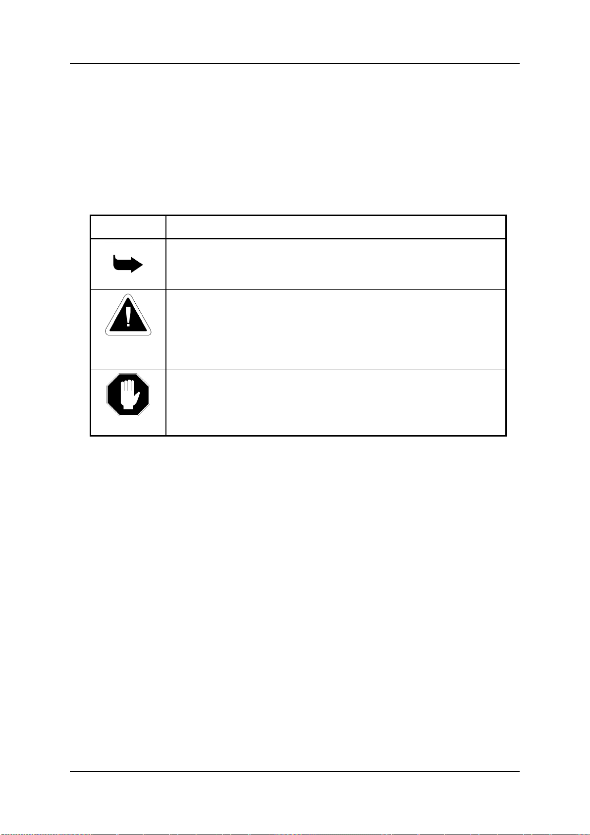
Symbol
Description
Note:
Information given in a note describes how the System
functions or provides a tip on how best to use it.
Caution:
Information given in a message labeled ―caution‖ refers to
the safe operation of the System and provides warnings
where the possibility for loss of data or damage to the
equipment exists.
Danger:
Information given in a message labeled ―danger‖ warns of
possible hazard to personnel and extreme hazard to the
System.
Hardware and Installation
Before You Begin
Conventions
The following symbols have been inserted on the left hand side of the
operating instructions in order to make it easier for the User to perform
procedures:
Notice
Information given in this document is subject to change without any notice.
Release 5.5 (March 2015)
1

Hypermedia Systems
Hardware and Installation
1 Hardware and Installation
Note: Hardware and installation vary depending upon the features included with the
Hypermedia Gateway system. Skip the sections that do not apply to your system.
This section contains:
Package Contents (section 1.1.1)
Safety Information (section 1.2)
System Components (section 1.3)
Typical Board Configurations (see 1.4)
Pre-Installation Preparations (section 1.5)
Cable Connections (section 1.6)
Inserting the SIM Cards (section 1.7)
Powering Up and LEDs Status (section 1.8)
Hypermedia Systems Ltd.
2

Hypermedia Systems
Hardware and Installation
1.1 Overview
Hypermedia Gateways provide integrated voice and SMS communications for
both on-site and remote users of small-to-large enterprises.
The Hypermedia HG-7000 SMS Pro Gateway is part of the HyperGateway
family of flexible, scalable platforms which empower cost-effective corporate
telephony over fixed, cellular and IP networks.
The HG-7000 Pro SMS gateway enables sending text-messages via SMS,
two-way SMS texting, SMS to email, PC to SMS, and reception of text
messages via SMS. It is supplied with a built-in SMS server software package
and easy-to-use client API tools, which enable third-party applications to send
and receive SMS messages. Additional applications are also available.
1.1.1 Package Contents
Depending upon configuration, the package should contain some or all of the
following:
The Hypermedia Gateway unit
Ethernet cables
1 or 2 power cords, depending upon the configuration
1 to 8 indoor antennas, depending upon the configuration
Hypermedia Software CD-ROM
The warranty certificate
1 SD card (standard gateway)
Release 5.5 (March 2015)
3

Hypermedia Systems
Hardware and Installation
1.2 Safety Information
Hypermedia Gateway works with a nominal mains supply voltage of 110–
240V AC. Hazardous voltages are present inside of this equipment. Some of
the parts can also have high operating temperatures.
To avoid injury and prevent equipment damage, observe the following safety
precautions:
Installation, service, and maintenance of the Hypermedia Gateway should
be done by qualified technicians only.
Do not connect the Hypermedia Gateway to any power source other than
the indicated nominal source.
The power supply cord must be connected to a socket with a valid ground.
This equipment should only be used in buildings with proper safety
ground.
When connecting the equipment, first, ensure that the ground connection
is connected to the rack ground or building ground.
When disconnecting the equipment, disconnect the ground connection
last.
Opening the housing may be dangerous and invalidates the warranty.
Only a qualified technician should open the housing. Before opening,
disconnect the power cable from the equipment.
The Hypermedia Gateway complies with all necessary safety standards.
Equipment connected to the Hypermedia Gateway must also comply with
the applicable safety standards.
The packaging is designed to protect against mechanical damage and
should be stored. Do not ship equipment unless it is properly packed in its
original wrapping and shipping containers.
Make sure that the equipment top and bottom are not blocked to air
movement. Leave 1U under and on top of the equipment for proper
ventilation.
Do not operate the Hypermedia Gateway in close proximity to potentially
hazardous areas. These includes areas such as, but not exclusively, fuel
stations, fuel depots, chemical works or during blasting.
The operation of radio transmitters, which includes cellular engines, can
impair the function of medical devices that have not been properly
shielded. Please ask the advice of your doctor or the manufacturer of the
medical device.
To avoid moisture condensation, allow time for the unit to adapt to the
ambient temperature before switching it on.
Hypermedia Systems Ltd.
4

Hypermedia Systems
Hardware and Installation
1.3 System Components
The Hypermedia Gateway unit is a 19" × 6U or 19" × 3U rack-mountable box
that connects to the local network. The HG-7000 Gateway comes in two main
series.
Standard: designed for the enterprise user; based on an embedded CPU.
Heavy-Duty: designed for high volumes of SMSs; based on a PC board.
The Hypermedia system contains the following:
A single power supply module. A dual power supply module is also
available.
A backplane with slots for the boards. The position of the boards varies
according to the product series.
The Hypermedia Server, which is an application that is embedded on the
HBN or on the PC1/2 board (depending upon system configuration).
The Hypermedia Server is controlled and managed by the browser-based
Hypermedia Management Console.
The Hypermedia Management Console (HMC), which is used by the
system administrator for remote configuration and monitoring of the
Hypermedia Gateway system. It connects to the gateway using TCP/IP
and is accessed via a standard WEB browser.
Release 5.5 (March 2015)
5
Hypermedia Systems
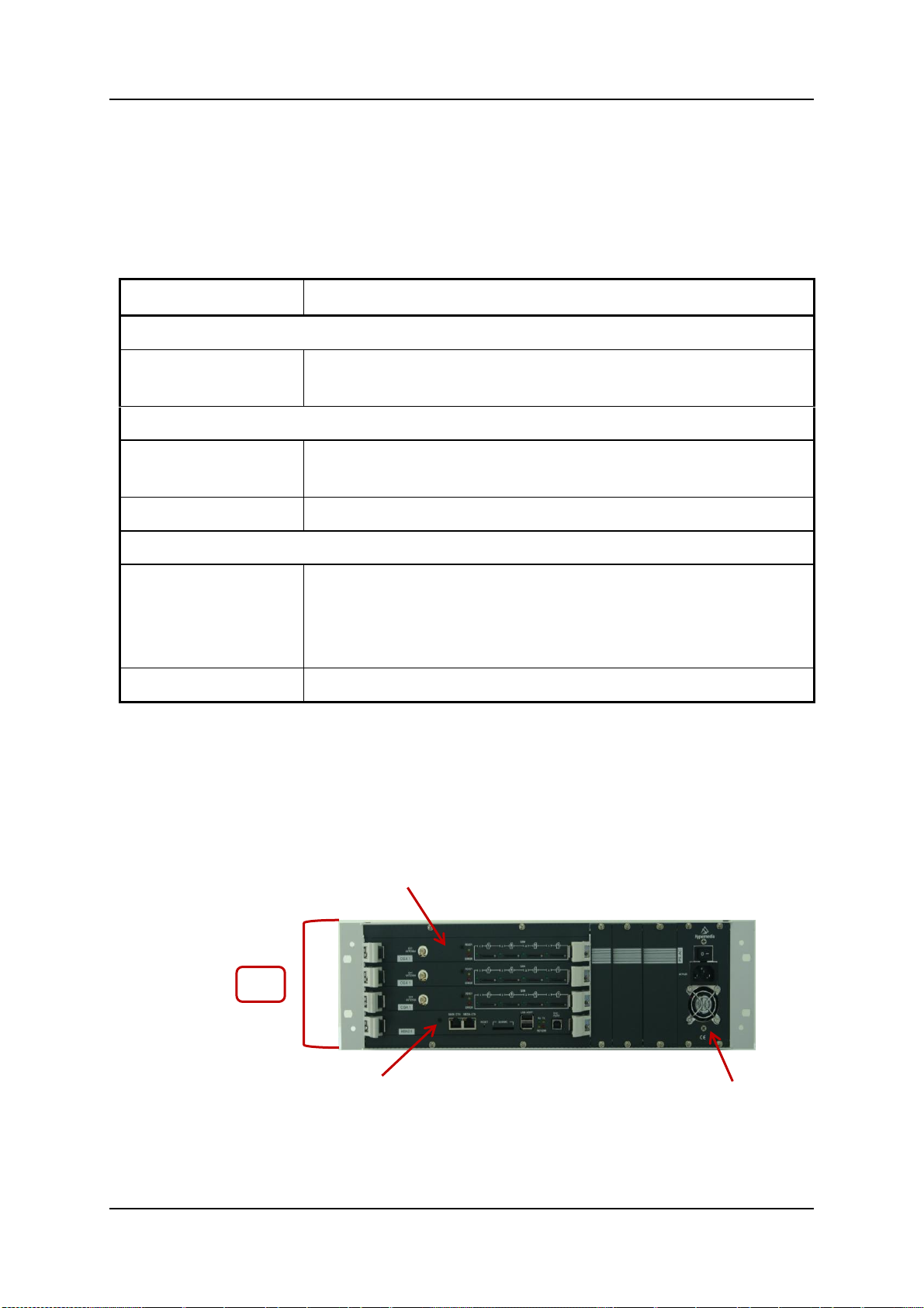
Board Name
Description
Standard Gateway Board
HBN
This Hybrid board provides the gateway management
function as well as the SMS server functionality.
Heavy-Duty Gateway Boards
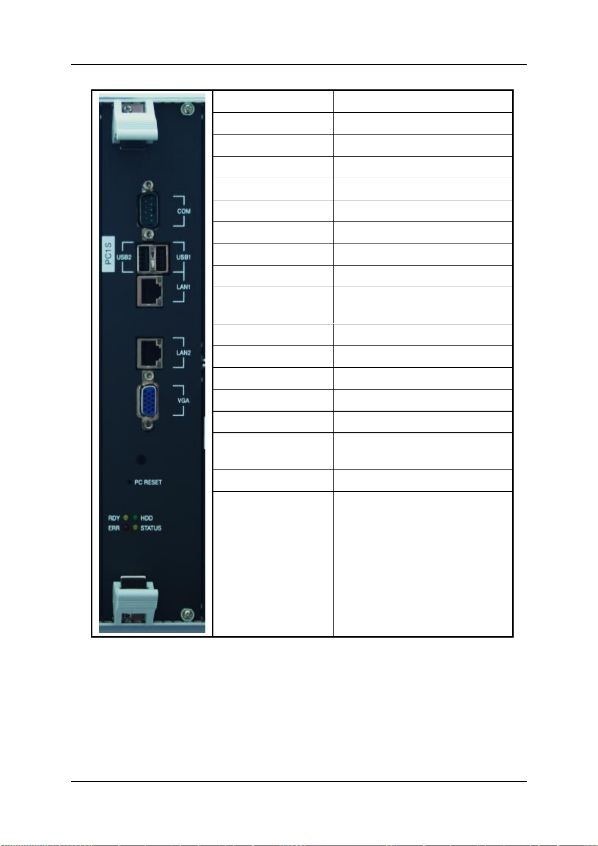
PC1/PC2
The PC board runs the HyperGateway server along
with an MG 2.1 board.
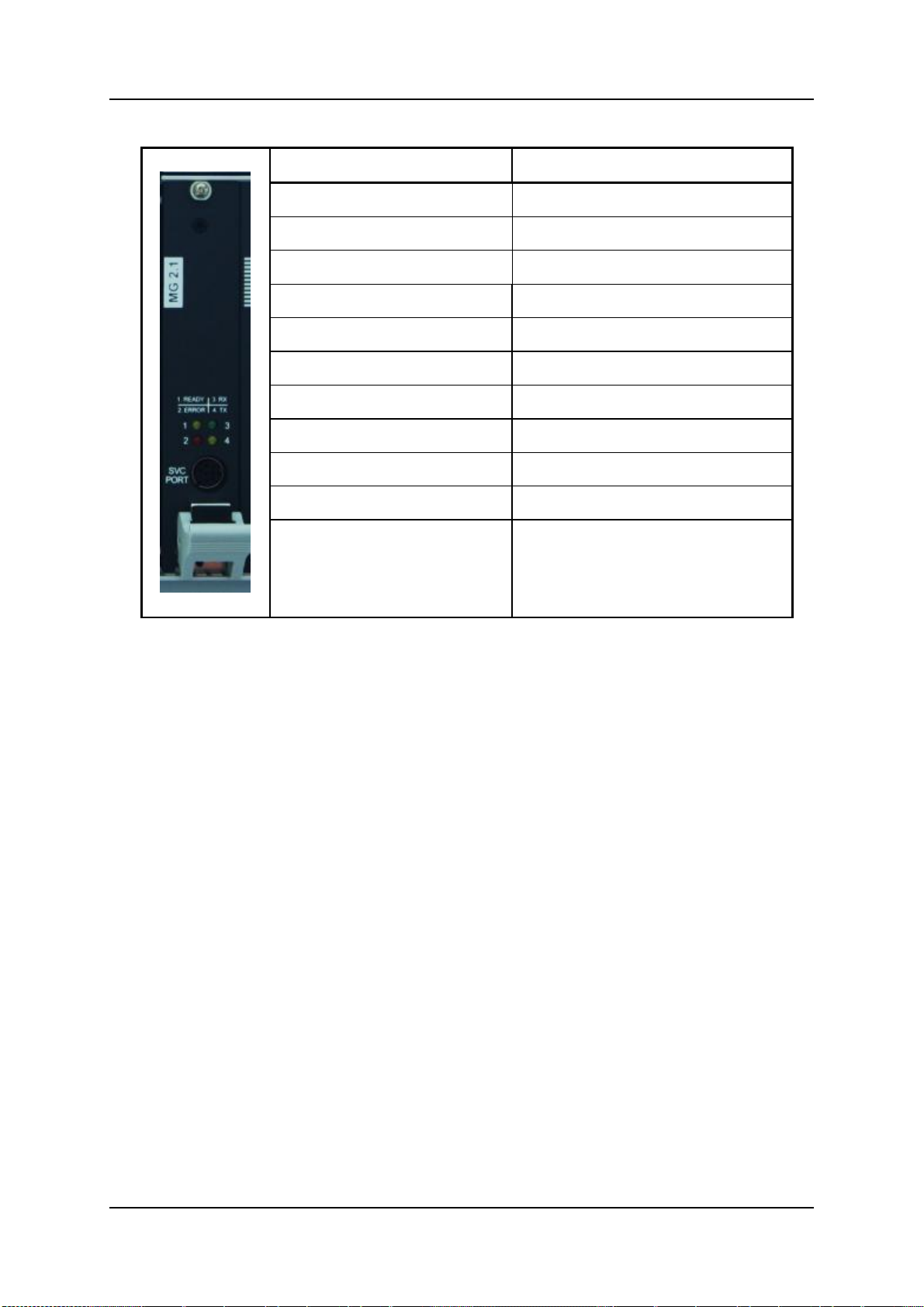
MG 2.1
This board provides the media matrix functionality.
Cross-Gateway Boards
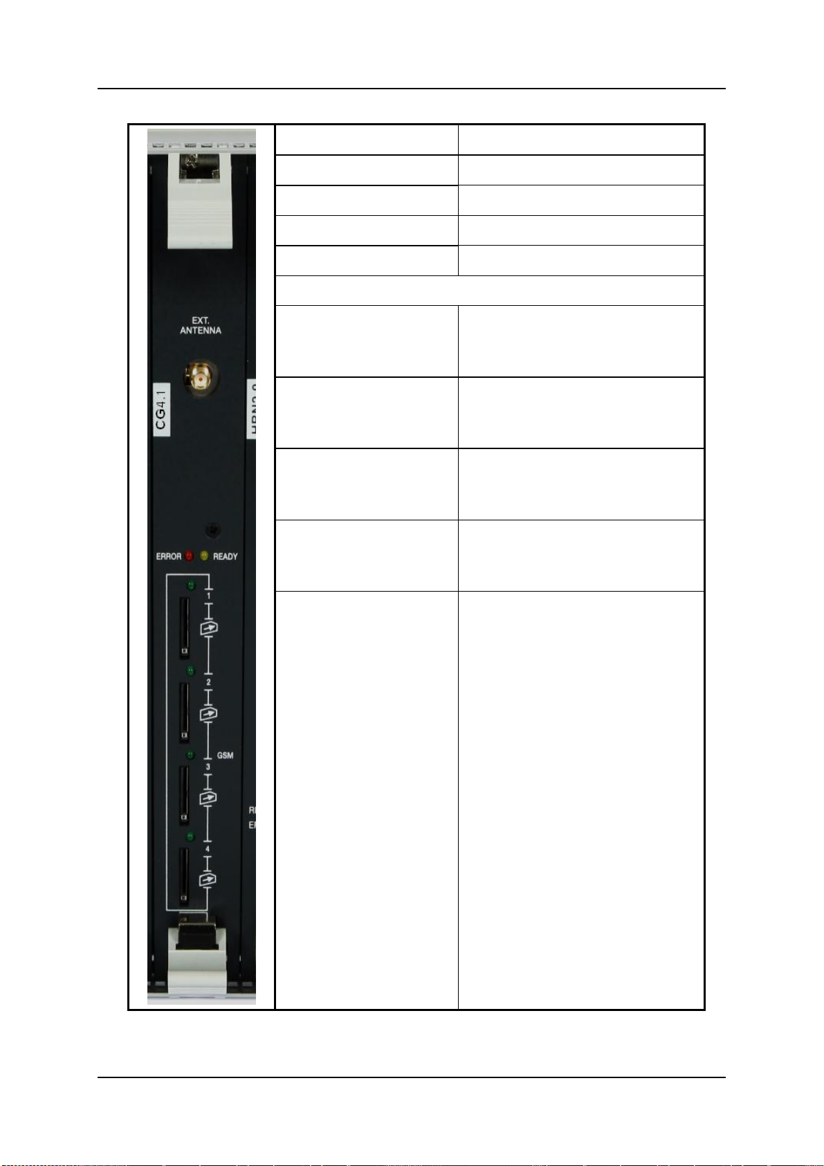
CG41/CC41/CU41
CG41 for GSM, CC41 for CDMA and CU41 for UMTS
is a single-slot board that contains four (4) cellular
channels with inbound and outbound SMS capabilities
for the various cellular networks.
S-HUB
This board provides SIM server connectivity.
HBN Board
CG Boards
Power Supply
3U
Hardware and Installation
1.4 Typical Board Configurations
The placement of the HG-7000 boards varies according to the product series.
The names and function of the boards are described in the following table.
Table 1. HG-7000 Boards and Function
1.4.1 3U Series
The following Figure 1 shows the 3U SMS Gateway supporting up to 12 ports
with API
Figure 1. 3U SMS Gateway
Hypermedia Systems Ltd.
6
Hypermedia Systems
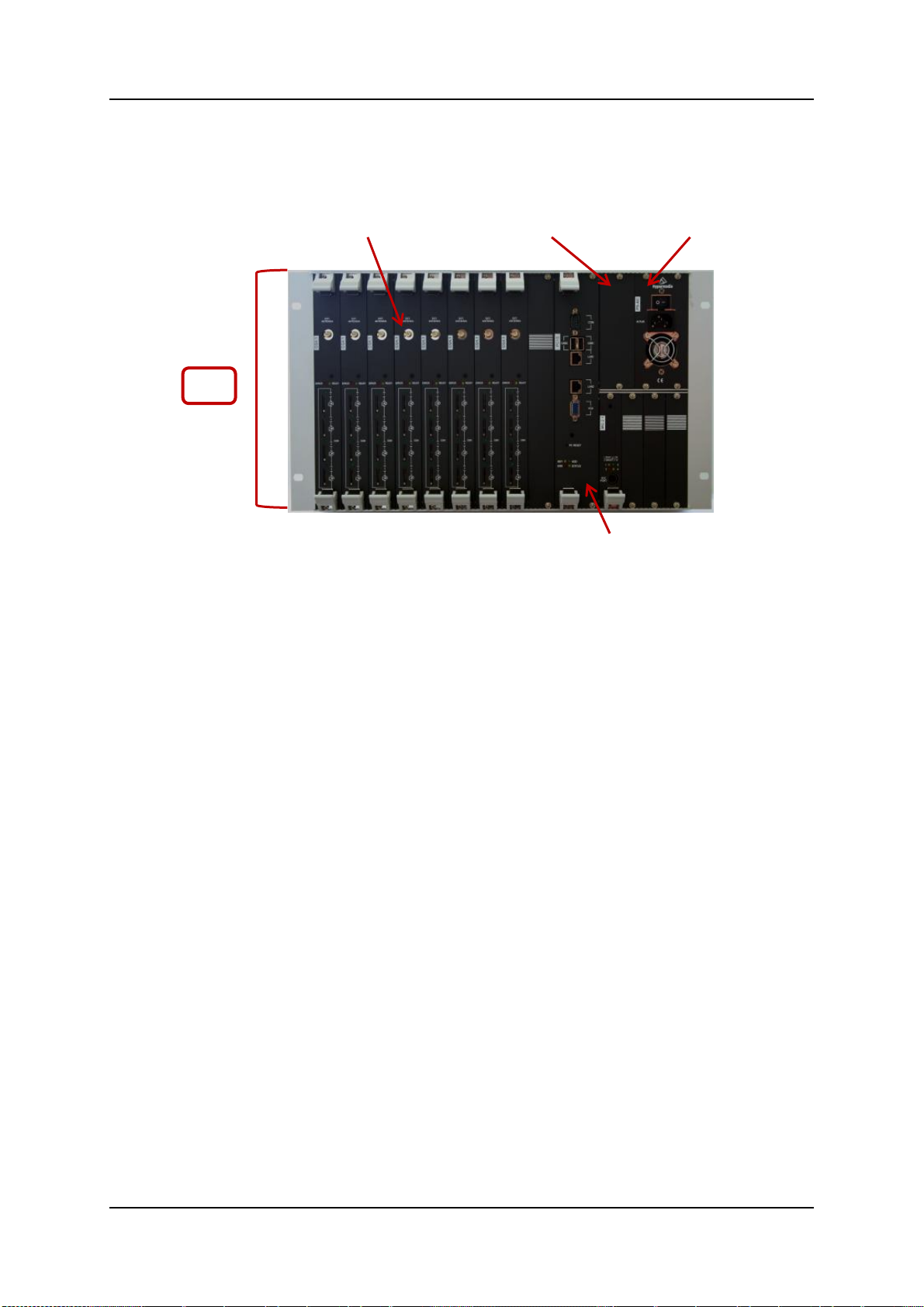
Power Supply
CG Boards
HBN Board
6U
Router Board
Hardware and Installation
1.4.2 6U Series
The following Figure 2 shows the 6U SMS Gateway, supporting up to 32 ports
Figure 2. 6U SMS Gateway, 32 ports
Release 5.5 (March 2015)
7

Hypermedia Systems
Hardware and Installation
1.5 Pre-Installation Preparations
Note: The installation procedure depends on the boards included with the Hypermedia
Gateway system. Skip the sections that do not apply to your system.
1. Install the Hypermedia Gateway in a 19‖ rack. Depending upon the
physical configuration, the unit requires a height of either 3U or 6U. In
addition, we recommend:
Avoid installing the device near computer rooms, computer monitors,
electrical cabinets, metal objects, and windows with fold aluminum
sheet.
Perform a cellular signal check before mounting the system. This can
be done by checking the Signal Strength and the Bit Error Rate ratio
on another mobile phone's display from the same operator and
system.
Ensure the device is protected against direct sunlight and heat. This
increases both the reliability of the operation as well as its service life.
2. Depending upon the configuration of your system, verify that you have
some or all of the following:
an Ethernet or WAN socket with a fixed IP address
SIM cards from your GSM operator. One SIM card is required for each
GSM channel
Notes:
The default LAN IP address for Hybrid-Based Gateways is 192.168.9.2
The default LAN IP address for PC - Based Gateways is 192.168.0.2
Hypermedia Systems Ltd.
8
Hypermedia Systems
Hardware and Installation
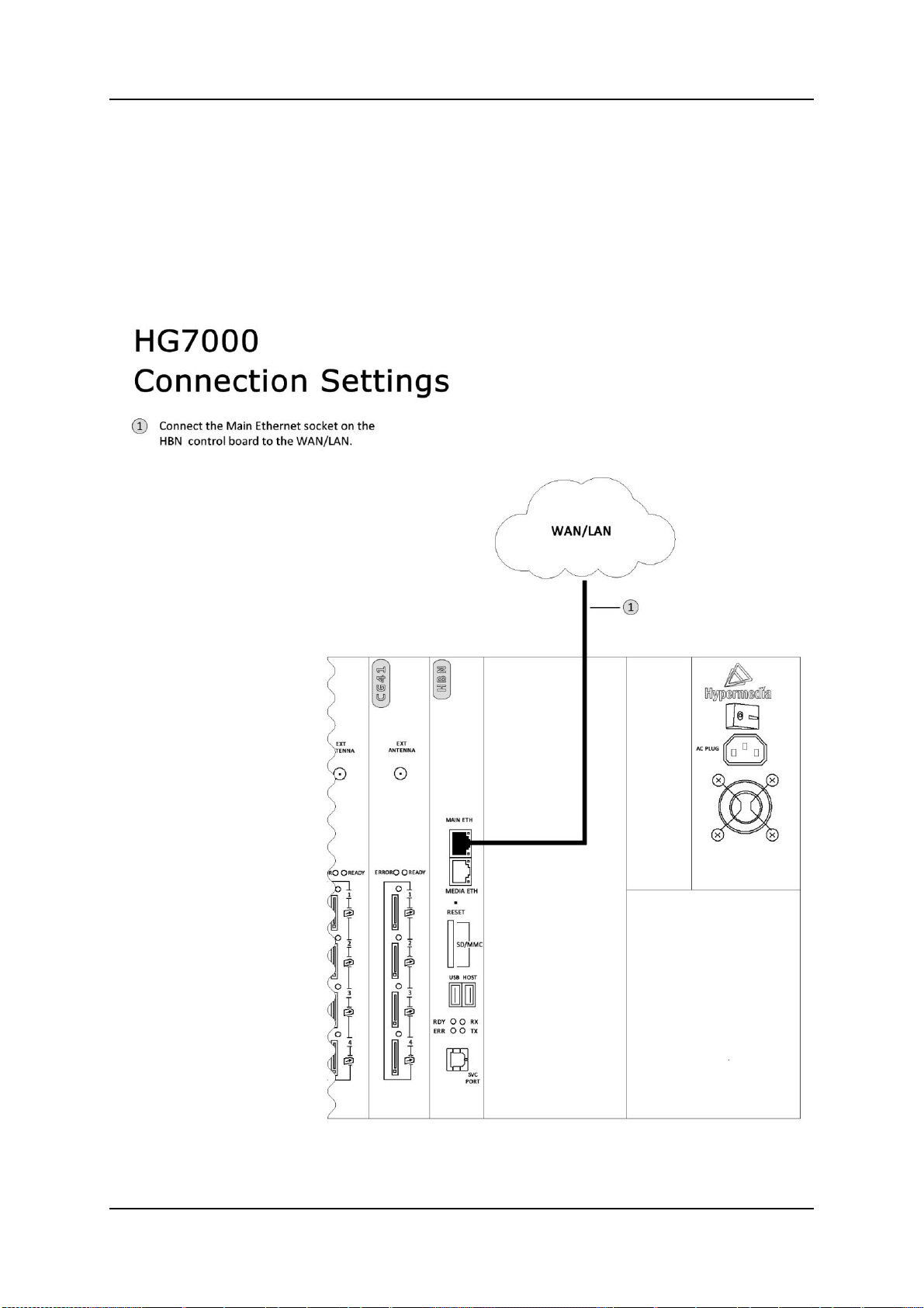
1.6 Cable Connections
There are two types of configurations:
Standard Gateway – Hybrid based (HBN)
Heavy-Duty Gateway – PC Based
1.6.1 Standard Gateway - Hybrid Based (HBN)
Figure 3. HG7000 - HBN Connection Settings
Release 5.5 (March 2015)
9
Hypermedia Systems
Hardware and Installation
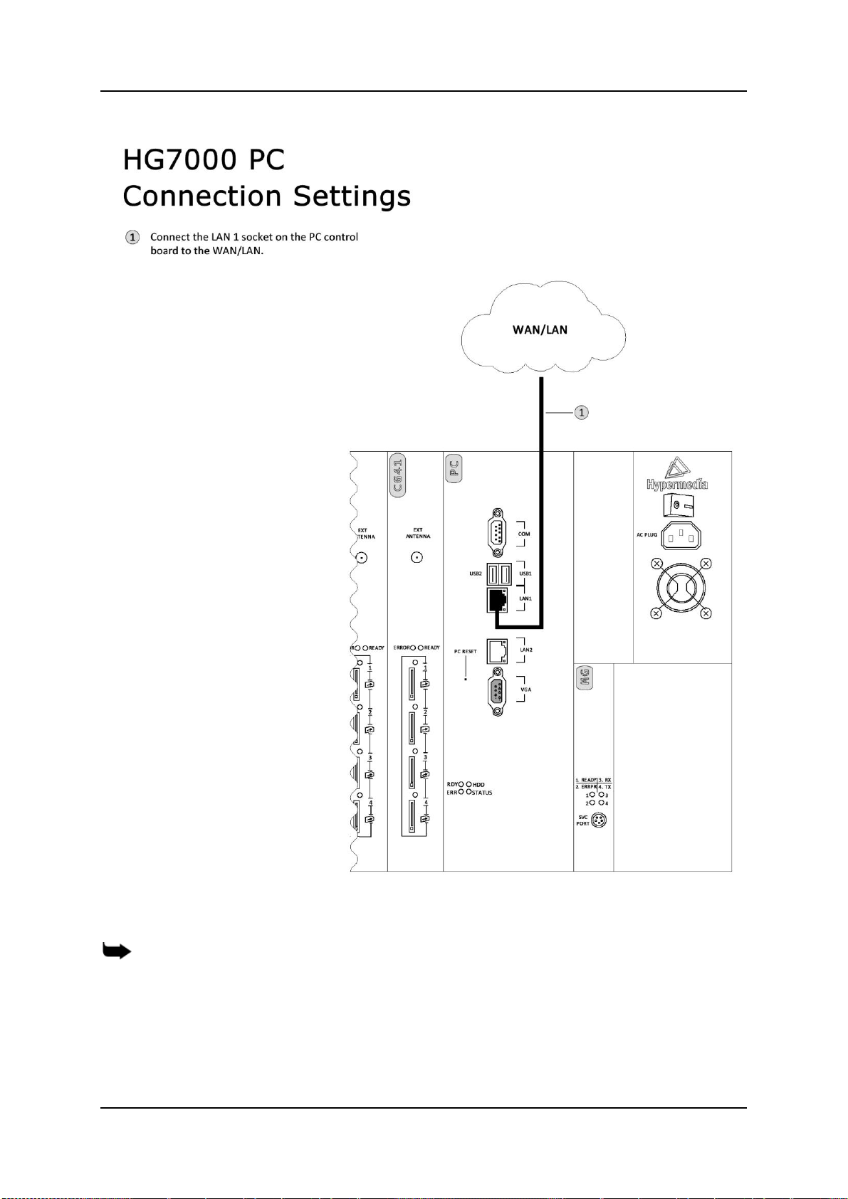
1.6.2 Heavy-Duty Gateway – PC Based
Figure 4. HG-7000 – PC Connection Settings
Note: The cables to the devices should be installed so that they do not cause any physical
risk. Power cables should be installed separate from the signal cables.
Hypermedia Systems Ltd.
10

Hypermedia Systems
Multi-SIM
Extender
Antenna Socket
Hardware and Installation
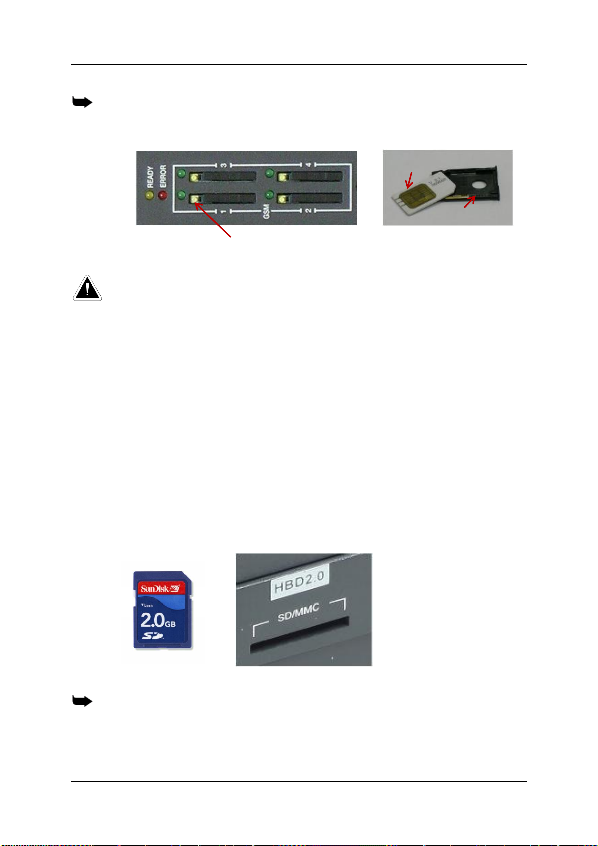
1.7 Inserting the SIM Cards
1. Insert the GSM SIM Cards. One SIM card should be used per each
cellular channel.
The SIM port is spring loaded. Slide the SIM card into the slot and it will
latch in place. To remove a SIM card, press the SIM card and it will pop
out.
Optionally, use the CG board’s multi-SIM extender:
a. Pull out the CG board.
Figure 5. CG Card with 12 Multi-SIM Extender
b. Slide back and pull up the SIM socket.
Caution: Do not use force on the SIM sockets.
Release 5.5 (March 2015)
11
c. Slide in the SIM cards.
d. Lock the SIM sockets.
Hypermedia Systems
SIM Card
SIM Drawer
Yellow button for drawer
Hardware and Installation
Note: Some versions of the CG board have SIM drawers. Push the small yellow button for
the SIM drawer to exit. Remove the SIM drawer, place the SIM card in the SIM drawer and
replace the SIM drawer.
2. Install the antennas. Each cellular card requires one antenna.
Caution: The provided antennas are for indoor use only, and will be irreversibly damaged if
placed outdoors. RF combiners and external antennas are sold separately.
a. Locate the antenna socket (see Figure ).
b. Fasten the antenna using the SMA connector. Do not use excess
force.
c. Tether all cables securely. Tethering helps prevents breakage of
connectors and damage to cellular cards.
d. Place the antenna indoors, where the reception level is high.
e. Optionally, to improve reception, place the magnetic back of the
antenna on a metal plate larger than 20 × 20 cm.
1.7.1 Inserting the SD Card (Standard Gateway)
The Gateway saves Call Detail Records (CDRs) on a Secure Digital (SD)
flash memory card that is supplied by Hypermedia. Insert the SD card into the
SD port of the HBN card.
Note: CDRs are displaced on a FIFO basis.
Hypermedia Systems Ltd.
12
Figure 6. SD Card and Port
Hypermedia Systems
Hardware and Installation
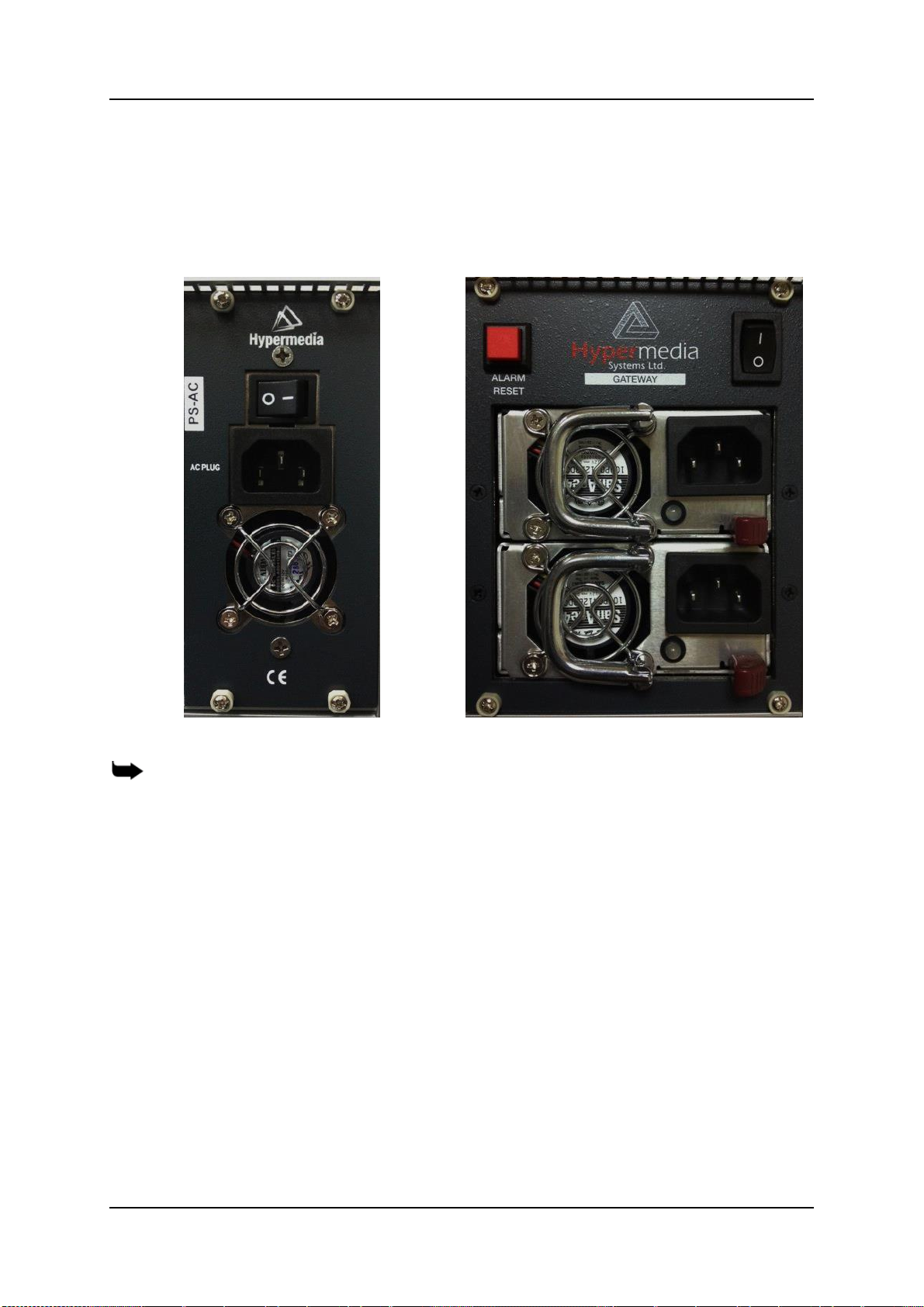
1.8 Powering Up and LEDs Status
1.8.1 Powering Up
1. Turn on the unit. The power panel is located at the top right corner of the
system.
Figure 7. Power Panel
Note: Redundant power supplies are optional. When installed, if one fails, or if the system is
powered up with just one power supply, an alarm will sound. To stop the alarm, press the
Alarm Reset button at the top left of the panel.
2. Check the LEDs:
For HBN LEDs, see Table 2
For PC Board status LEDs, see Table 3
For MG Board Status LEDs, see Table 4
For Cellular Card Green SIM LEDs, see Table 5
1.8.2 LEDs Status
Following are explanations of LED behavior for each of the Hypermedia
Gateway’s cards.
Release 5.5 (March 2015)
13
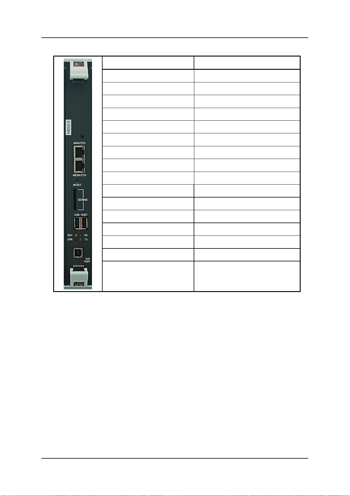
Hypermedia Systems
State
Explanation
Main ETH
Yellow
LAN Traffic
Green
LAN Connection
Media ETH
Yellow
LAN Traffic
Green
LAN Connection
Red LED - ERR
Blinking
Board Error
Yellow LED - RDY
Off
Power is OFF
Short Blink
Board Ready
Fast Blink
Maintenance mode
Green LED - RX
On
Internal Communication
Yellow LED - TX
On
Internal Communication
Hardware and Installation
Table 2. HBN LEDs
Hypermedia Systems Ltd.
14
Hypermedia Systems
State
Explanation
LAN 1
Yellow
LAN Traffic
Green
LAN Connection
LAN 2
Yellow
LAN Traffic
Green
LAN Connection
Red LED - ERR
Blinking
Board Error
Yellow LED -
RDY
Off
Power is OFF
Short Blink
Board Ready
Fast Blink
Maintenance mode
Green LED - HDD
On
Disk Activity
Yellow LED -
Status
On
Internal Communication
Hardware and Installation
Table 3. PC Board status LEDs
Release 5.5 (March 2015)
15
Hypermedia Systems
State
Explanation
Red LED - ERR
Blinking
Board Error
Yellow LED - RDY
Off
Power is OFF
Short Blink
Board Ready
Fast Blink
Maintenance mode
Green LED - RX
On
Internal Communication
Yellow LD - TX
On
Internal Communication
Hardware and Installation
Table 4. MG 2.1 Board Status LEDs
Hypermedia Systems Ltd.
16
Hypermedia Systems
State
Explanation
Red LED
On
Board Error
Yellow LED
Short blink
Board Ready
SIM Cards - Green LED
Flashing
A SIM card is not installed in
this channel or the port is
still being initialized.
Off
No reception; the channel is
not registered to a cellular
network.
Short blinks (mostly
Off)
Stand by; the channel is
registered but no call is in
progress.
Long blinks (mostly
On)
User is either dialing out or
receiving a call on this
channel.
Steady On
In use. A call is in progress.
Hardware and Installation
Table 5. Cellular Card LEDs Status
Release 5.5 (March 2015)
17

Hypermedia Systems
HMC Quick Start
2 HMC Quick Start
Use the Hypermedia Management Console (HMC) to configure and monitor a
Hypermedia Gateway from a remote location. Access to the Gateway is over
TCP/IP using a standard version of Internet Explorer.
Note: The Hypermedia Management Console is customized to match the specific order.
According to the customization, some branches of the HMC may or may not appear.
This section contains:
Installation (section 2.1)
Setting the IP address (section 2.2)
Start-up and Initial Connecting (section 2.3)
Save and Backup/Restore Configuration Settings (section 2.4)
Hypermedia Systems Ltd.
18
Hypermedia Systems
HMC Quick Start
2.1 Installation
To install the Hypermedia Management Console program:
1. Ensure that the computer matches the following minimum system
requirements:
Windows XP, Vista, Windows 7 or 8
Internet Explorer 7 or above
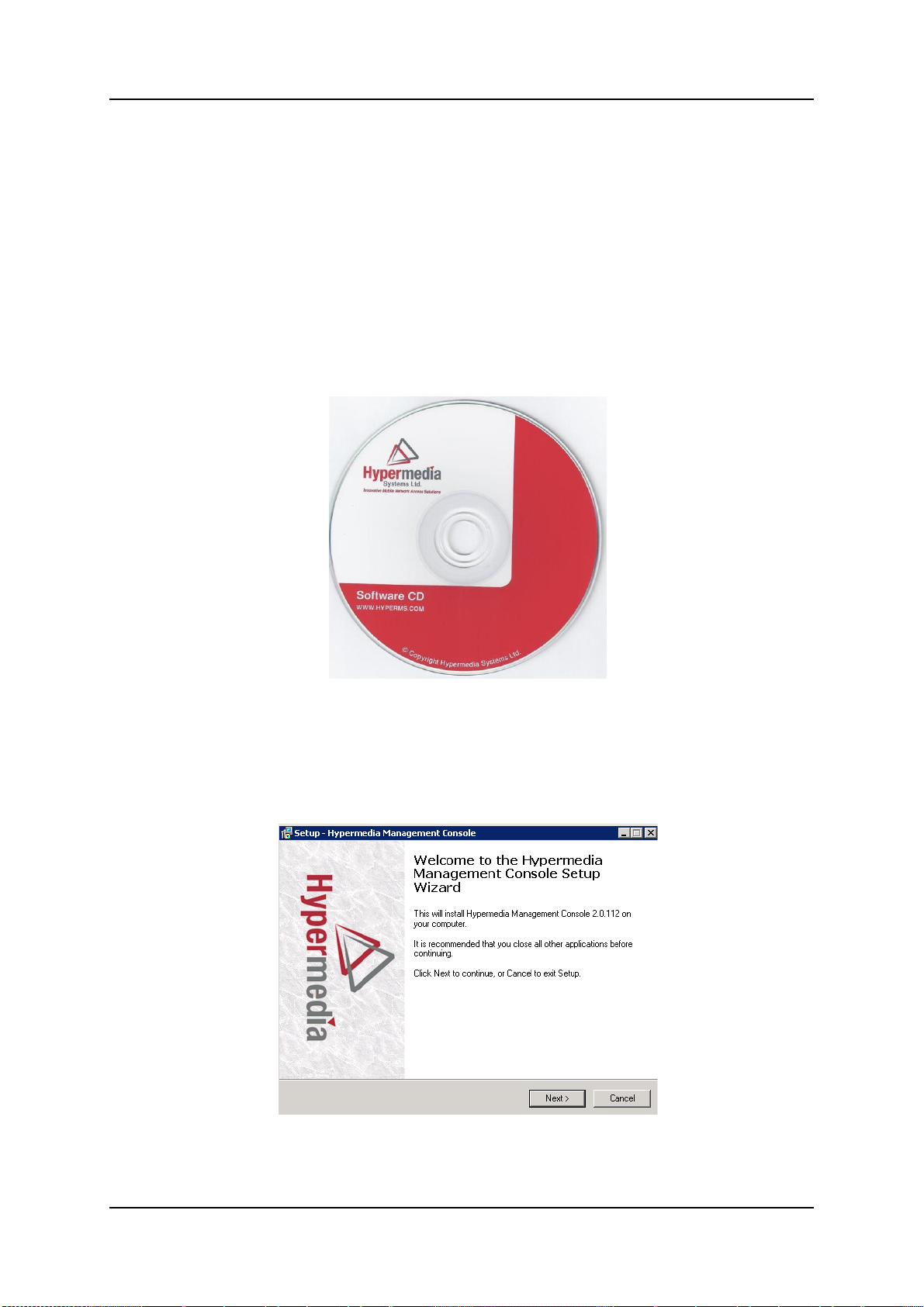
2. Ensure that you have access to the installation file. It is included with the
Hypermedia Gateway CD-ROM.
Figure 8. Hypermedia Gateway CD-ROM
The installation file name begins with the letter HMC and ends with the
extension .exe. The specific name depends upon the type of installation.
3. Double-click the file HMCxxx-xxx.exe file. The Setup program starts.
Figure 9. Setup Welcome Screen
4. Click Next. The License Agreement is displayed.
Release 5.5 (March 2015)
19
Hypermedia Systems
HMC Quick Start
5. To continue, you must accept the terms of the agreement. Click I accept
the agreement and click Next. The Select Destination Location window is
displayed.
6. Define the location where the program files will be installed. The default
location is "C:\ProgramFiles\Hypermedia". Click Next. The Select Start
Menu Folder is displayed.
7. Define the name of the program group that will be added to the Start
Menu. The default name is Hypermedia. Click Next. The Additional Tasks
window is displayed.
8. Optionally, select the checkbox to create a Desktop shortcut. Click Next.
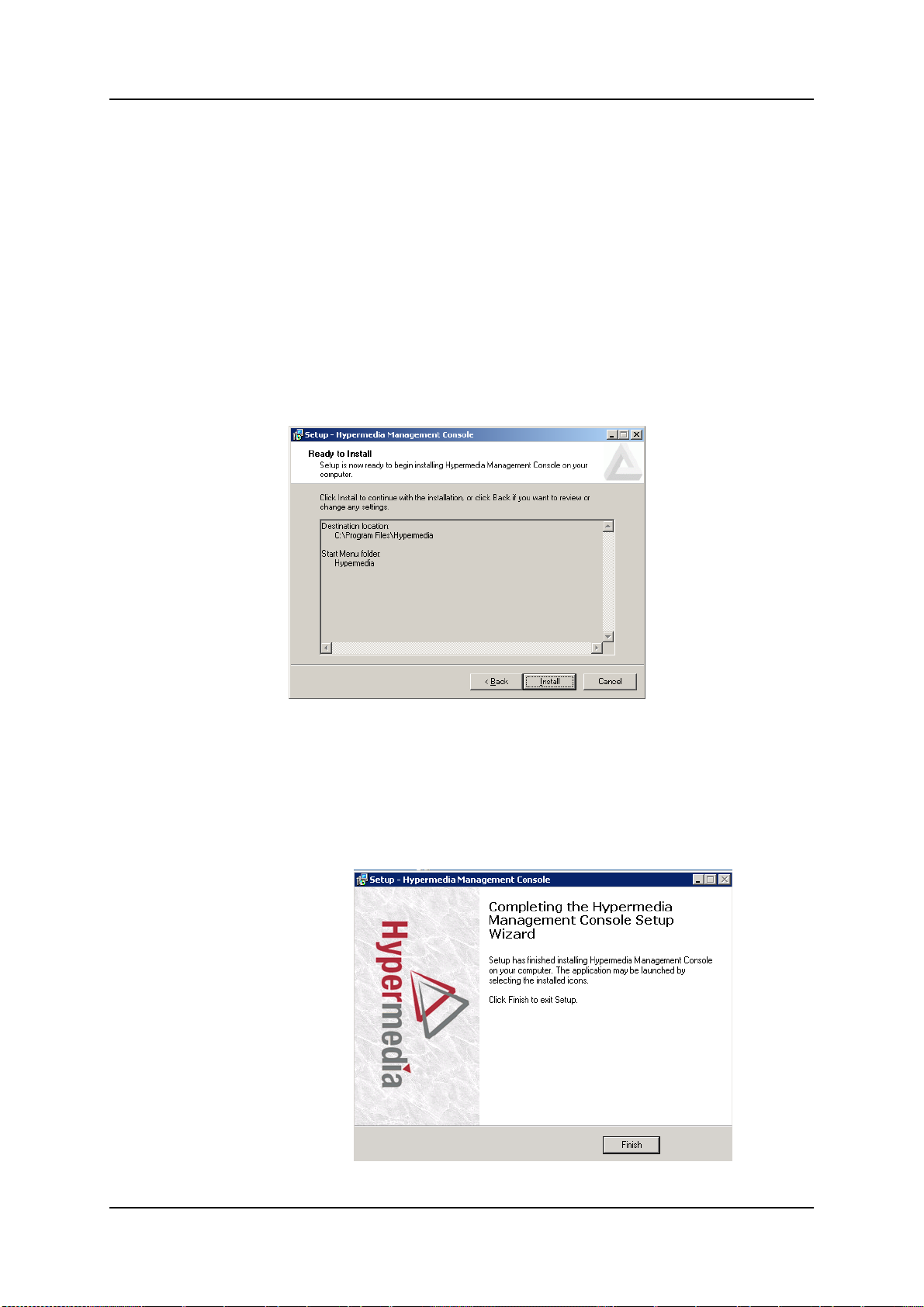
The ―Ready to Install‖ window is displayed.
Figure 10. Setup Ready to Install Screen
9. Click Install. The installation process begins. A progress bar reports the
progress of the installation.
After the installation is complete, click Finish. The installation program
creates a program group in the Start menu and, optionally, a Desktop
shortcut
Hypermedia Systems Ltd.
20
Figure 11. Setup Finish Screen

Hypermedia Systems
HMC Quick Start
2.2 Setting the IP Address
To change or set the IP address:
1. From the Hypermedia program group, select Server List. The HyperGateway Servers Address List screen opens in the default browser.
2. If required, click the warning bar at the top of the screen and from the
dropdown menu click Allow Blocked Content. Confirm your choice by
clicking Yes on the confirmation message.
Figure 12. Hypermedia Gateway Server List
Note: To avoid recurring displays of the warning bar, browse from the Explorer menu bar to
Tools > Internet Options > Advanced and select Allow active content to run in
files on My Computer.
Your Gateway appears in the Server List with its default address.
3. Click (Change Server Settings). The Login screen is displayed.
Figure 13. The Login Screen
4. Enter the password and click Submit. The default password is admin. The
HGS Setup Parameters screen is displayed.
Release 5.5 (March 2015)
21

Hypermedia Systems
HMC Quick Start
5. From the HGS Server system function line, click Stop. A confirmation
message indicates that the service has stopped successfully.
Figure 14. HGS Setup Parameters Screen
6. On the IP Configuration line, click Change. The IP Address screen is
displayed.
Figure 15. IP Address Screen
7. Enter the new IP Address parameters.
Note: Setting the IP address through this page will permanently affect the Gateway IP
address settings once rebooted.
8. Click Update. Focus is returned to the HGS Setup Parameters Screen.
9. From the HGS Server line, click Start. A confirmation message indicates
that the service started successfully.
Hypermedia Systems Ltd.
22

Hypermedia Systems
HMC Quick Start
2.3 Start-up and Initial Connecting
To run the Hypermedia Management Console:
1. Click the Windows Start button > Programs > Hypermedia. The
Hypermedia program group expands.
2. Click Hypermedia Management Console. The program opens in the default
browser.
Figure 16. HMC Connection Screen
3. Click the warning bar at the top of the screen and, from the dropdown
menu, click Allow Blocked Content. Confirm your choice by clicking Yes on
the confirmation message.
Figure 17. HMC Connection Screen
Note: To avoid recurring displays of the warning bar, browse from the Explorer menu bar to
Tools > Internet Options > Advanced and select Allow active content to run in
files on My Computer.
4. Enter the IP address:
Release 5.5 (March 2015)
23

Hypermedia Systems
HMC Quick Start
a. Expand the Configure branch.
b. Expand the Server Settings branch.
c. Select IP address. The Server Address screen is displayed.
d. Enter the IP address and click Apply Settings
Figure 18. HMC Server Address Screen
Note: If the Gateway is located behind a firewall, enable traffic on TCP ports 8878, 8879, 80
and 22. For details, contact the network administrator.
Note: The above IP address setting does not affect the address of the Gateway. It only
defines the IP address the HMC will attempt to connect to.
5. Either press F5 or click the browser’s Refresh button. The authorization
screen is displayed.
Figure 19. HMC Login Authorization Request
Note: The default password is admin.
6. Enter the password and click Submit. A confirmation message is
displayed, indicating you have successfully connected to the Hypermedia.
The Connection State screen is displayed.
Hypermedia Systems Ltd.
24

Hypermedia Systems
HMC Quick Start
Figure 20. HMC Connection State Display
A list of all services is displayed, including their versions and current
activation/installation state.
Release 5.5 (March 2015)
25

Hypermedia Systems
HMC Quick Start
2.4 Save and Backup/Restore Configuration Settings
2.4.1 Save All
Use the configuration branch to permanently save all the configuration
settings in the HyperGateway
2.4.2 Store Settings on Cards
Use this option to permanently save all the configuration settings in the
Hypermedia Gateway. This process might take up to 60 seconds.
2.4.3
Figure 21. Save All Settings configuration branch
Backup/Restore
Use this option to download the entire configuration of the Gateway to your
PC. The downloaded backup file can then be uploaded by performing a
system restore.
Hypermedia Systems Ltd.
26
Figure 22. Backup and Restore

Hypermedia Systems
Configuring a Cellular Card
3 Configuring a Cellular Card
This section contains:
Cellular Card and System Terminology (section 3.1)
Media Connections (section 3.2)
PIN Codes (section 3.3)
Reset (section 3.4)
Information Screens (section 3.5)
Locks (section 3.6)
SIM Select (section 3.7)
Cell Selection (section 3.8)
Settings (section 3.9)
Network Parameters (section 3.10)
USSD SIM Balance (section 3.11)
Monitoring Cellular Cards (section 3.12)
Release 5.5 (March 2015)
27

Hypermedia Systems
Spring-loaded
SIM ports
Additional
SIM cards
Module
Configuring a Cellular Card
3.1 Cellular Card and System Terminology
A cellular card has 4 modules, each of which can have 1 to 4 SIM holders.
Therefore, each card can hold up to 16 SIM cards. The Hypermedia Gateway
can include several cards.
The first SIM cards of each module are loaded into the spring-loaded SIM
ports from the front of the Cellular Card.
Figure23. Cellular Card SIM Ports and Holders
Some of the parameters can be applied to specific SIM cards, some to a
specific module, some to the entire cellular card and some to all the cards in
the system.
Hypermedia Systems Ltd.
28

Hypermedia Systems
Configuring a Cellular Card
3.2 Media Connections
Use the Media Connection screen to configure the connections from the
Cellular card channels to other cards and channels of the system, including
the PRI cards (E.1) and the VoIP cards (MG). Connections can be either
static or dynamic, as in the case of LCR.
For example, you can assign each cellular channel to a specific E1 channel.
In this case, every time there is an incoming call from a specific E1 channel, it
will be routed to the configured channel on the cellular card and vice versa.
Note: The matrix can be configured in any combination. Routing can be assigned between
any cellular channel and any other channel in the system, including other cellular channels.
3.2.1 Associating/Linking Cellular Channels
To associate a cellular channel with another media channel:
1. From the Cellular Cards branch of the HMC navigation pane, , click the
Media Connections sub-branch. The Media Matrix is displayed.
Figure 24. Cellular Media Matrix screen
2. If more than one slot is displayed, select a specific cellular card. The
Media Matrix of that cellular card is displayed.
3. Click within a channel row. The row turns yellow.
4. Click Edit. The row becomes configurable.
Release 5.5 (March 2015)
29

Hypermedia Systems
Configuring a Cellular Card
Figure 25. Media Matrix Row when Configurable
5. From the first dropdown list, allocate the channel to a card by selecting the
card.
Note: If all of the card’s channels are already allocated, the message ―Fully allocated‖
appears.
6. From the second dropdown list, assign the channel to a specific channel
on the target card.
Figure 26. Assigning a Target Link
7. Click Save. The configuration dropdown boxes are hidden.
8. Optionally, repeat the process for additional channels and other media
types.
9. Click Apply Settings and wait for ―Configuration Saved‖ to be displayed.
3.2.2 Auto Linking
Enables associating all channels of one media card to another media card.
To create an auto-link:
1. From the Cellular Cards branch of the HMC navigation pane, click the
Media Connections sub-branch. The Media Matrix is displayed.
Hypermedia Systems Ltd.
30

Hypermedia Systems
Configuring a Cellular Card
Figure 27. Auto Media connecting
2. If more than one slot is displayed, select a specific cellular card. The
Media Matrix of that cellular card is displayed.
3. Click within a channel row. The row turns yellow.
4. Click Auto Link.
All channels can be associated with one media card to another: card X
channel 1 to card Y channel 1, card X channel 2 to card Y channel 2, etc.
3.2.3 Unlinking Cellular Allocations
To break an allocation:
5. From the HMC navigation pane Cellular Card branch, click the Media
Connections sub-branch. The Media Matrix is displayed.
6. Click within a channel row. The row turns yellow.
Figure 28. Breaking a Target Link
7. Click Unlink.
8. Click Apply Settings and wait for ―Configuration Saved‖ to be displayed.
Release 5.5 (March 2015)
31

Hypermedia Systems
Configuring a Cellular Card
3.3 PIN Codes
Use the PIN Codes screen to configure the PIN code that the Gateway uses
when a SIM card with an active PIN is inserted. For more information
regarding the PIN code, consult your cellular provider.
To enter a SIM card’s PIN code:
1. From the Cellular Cards branch of the HMC navigation pane, click the PIN
Codes sub-branch. The PIN Codes screen is displayed.
Figure 29. HMC Cellular PIN Codes Screen
2. If more than one slot is displayed, select a specific Cellular Card. The PIN
Codes screen of that cellular card is displayed.
3. Enter the PIN code into the associated Module’s field.
4. Click Apply Settings and wait for ―Configuration Saved‖ to be displayed.
Hypermedia Systems Ltd.
32

Hypermedia Systems
Configuring a Cellular Card
3.4 Reset
Use the Cellular Card Reset screen to reset either the entire cellular card or a
specific cellular module.
To reset a cellular card or module:
1. From the Cellular Cards branch of the HMC navigation pane, click the
Reset sub-branch. The Reset screen is displayed.
Figure 30. Cellular Card Reset screen
2. If more than one slot is displayed, select a specific Cellular Card. The
Reset screen of that cellular card is displayed.
Caution: There is no confirmation message. The Reset command is sent as soon as the
reset button is clicked.
3. Click Reset. The screen confirms that the Reset command has been sent.
Release 5.5 (March 2015)
33

Hypermedia Systems
Configuring a Cellular Card
Figure 31. Reset screen after sending the Reset command
Hypermedia Systems Ltd.
34

Hypermedia Systems
Configuring a Cellular Card
3.5 Information Screens
Several HMC screens display information.
3.5.1 Module Info
Use the Module Info screen to review information about the modules of a
cellular card.
1. From the Cellular Cards branch of HMC navigation pane, click the Module
Info sub-branch. The Module Info screen is displayed.
Figure 32. HMC Module Info Screen
2. If more than one slot is displayed, select a specific Cellular Card. The
Module Info screen of that cellular card is displayed
3.5.2 Serial Numbers
Use the Serial Numbers screen to view the GSM Modules International Mobile
Equipment Identity (IMEI) and the SIMs International Mobile Subscriber
Identity (IMSI).
1. From the HMC navigation pane Cellular Cards branch, click the Serial
Numbers sub-branch. The Serial Numbers screen is displayed.
Release 5.5 (March 2015)
35

Hypermedia Systems
Configuring a Cellular Card
2. If more than one slot is displayed, select a specific Cellular Card.
Figure 33. HMC Serial Numbers Screen
Hypermedia Systems Ltd.
36

Hypermedia Systems
Configuring a Cellular Card
3.6 Locks
Use Locks to restrict access to specific GSM operators and/or a specific SIM
card. When a lock is defined, the Gateway will only accept calls from an
operator or a SIM card that matches the Lock number.
In addition, use Locks to prevent roaming handover in cases where the
Gateway is located close to another county or a country border.
To define a Lock number:
1. Ensure the following:
You have obtained the codes from the cellular operator.
The cellular modules support SIM locks.
2. From the Cellular Cards branch of the HMC navigation pane, click the
Locks sub-branch. The Locks screen is displayed.
Figure 34. HMC Cellular Locks Screen
3. If more than one slot is displayed, select a specific Cellular Card. The
Locks screen of that cellular card is displayed.
4. Fill the fields of the following:
SIM Lock
Use SIM Locks to avoid using SIM cards other than those whose Mobile
Network Code (MNC) and Mobile Country Code (MCC) values have been
entered.
Operator Lock
Use Operator Locks to avoid registration to any network other than the
one whose MNC and MCC values have been entered.
5. Click Apply Settings and wait for ―Configuration Saved‖ to be displayed.
Release 5.5 (March 2015)
37

Hypermedia Systems
Configuring a Cellular Card
3.7 SIM Select
Use the SIM Select screen to manually select and activate a SIM card for
current use. SIM Select should not be used when SIM Auto Manage is active.
The definition can be applied just to the module, to all 4 modules on the card,
or to all the cellular cards in the system (see Cellular Card and System
Terminology in section 3.1).
To manually select SIM cards:
1. From the Cellular Cards branch of the HMC navigation pane, click the SIM
Select sub-branch. The SIM Select screen is displayed.
Figure 35. HMC SIM Select Screen
2. If more than one slot is displayed, select a specific Cellular Card. The SIM
Select screen of that cellular card is displayed.
3. Select an application option:
Module Settings
Applies the SIM configuration to the specific module.
Hypermedia Systems Ltd.
38

Hypermedia Systems
Configuring a Cellular Card
Entire Card
Applies the SIM configuration to all the modules on the card.
Figure 36. HMC SIM Select Screen – selection for entire card
Entire System
Applies the SIM configuration to all the cards in the system.
4. Click Apply Settings and wait for ―Configuration Saved‖ to be displayed.
Release 5.5 (March 2015)
39

Hypermedia Systems
Configuring a Cellular Card
3.8 Cell Selection
Use the Cell Selection screen to manually camp on a cellular site. Most often
the user will select the strongest cell site. However, if the Base Transceiver
Station (BTS) or tower is locked, this service cannot be applied.
Note: This feature is only available when Wavecom GSM or Telit GSM/UMTS modules are
installed.
To camp on a site:
1. From the HMC navigation pane Cellular Cards branch, click the Cell
Selection sub-branch. The Cell Selection screen is displayed.
Figure 37. HMC Cellular Cell Selection Screen
2. If more than one slot is displayed, select a specific Cellular Card. The Cell
Selection screen of that cellular card is displayed.
3. From the Select module dropdown box, select a module. This is the
module that the Camp selection will be applied to.
4. In one of the CellID boxes, click Camp. The screen indicates Camp Cell
and new controls are displayed at the top of the screen.
Hypermedia Systems Ltd.
40

Hypermedia Systems
Configuring a Cellular Card
Figure 38. HMC Cellular Cell Selection with Options Screen
5. Optionally, to camp all the card’s modules on the same cell, click Camp all
modules on.
Release 5.5 (March 2015)
41

Hypermedia Systems
Configuring a Cellular Card
3.9 Settings
Use the Settings screen to enable and disable advanced parameters. For
assistance with these, contact Technical Support.
1. From the Cellular Cards branch of the HMC navigation pane, click the
Settings sub-branch. The Cellular Card Settings screen is displayed.
Figure 39. HMC Cellular Card Settings Screen
2. If more than one slot is displayed, select a specific Cellular Card. The
Cellular Card Settings screen of that cellular card is displayed.
3. Click Apply Settings and wait for Configuration Saved to be displayed.
Hypermedia Systems Ltd.
42

Hypermedia Systems
Configuring a Cellular Card
3.10 Network Parameters
Use the Network Parameters screen to define the bandwidth used by a
carrier.
1. From the Cellular Cards branch of the HMC navigation pane, click the
Network Parameters sub-branch. The Cellular Card Network Parameters
screen is displayed.
Figure 40. HMC Cellular Card Network Parameters Screen
2. If more than one slot is displayed, select a specific Cellular Card. The
Network Parameters screen of that cellular card is displayed.
3. Select the matching bandwidth from the dropdown menu. For a table of
bandwidths per country, see http://en.wikipedia.org/wiki/
Mobile_network_code
4. From the HMC navigation pane, click the Save/Load branch and then click
Save All Settings.
Release 5.5 (March 2015)
43

Hypermedia Systems
Configuring a Cellular Card
3.11 USSD SIM Balance
Use the USSD SIM Balance screen to check the balance remaining on a
prepaid SIM card and to add value to a SIM card (recharge/top-up).
1. Ensure that your Service Provider has given you a USSD string for
checking balance and a second string for adding value (recharging) the
SIM card.
2. From the HMC navigation pane Cellular Cards branch, click the USSD SIM
Balance sub-branch.
Figure 41. HMC Cellular USSD SIM Balance Screen
3. Enter the Balance checking USSD string.
4. Enter the Recharging USSD string.
5. Select or clear the Check All checkbox. When selected, the Hypermedia
Management Console will check the balance of all the SIM cards.
6. Click (Check Balance). The balance is displayed in the USSD Reply
column.
7. Optionally, recharge the SIM card:
a. Ensure that you have a recharge string. Often, the string is displayed
on recharge cards after a removing a layer of ink that hides the string.
b. Enter the string into the Recharge Balance field.
c. Click the (Recharge Balance) button.
8. Optionally, click the (Excel) icon to save the results as an Excel file.
Hypermedia Systems Ltd.
44

Hypermedia Systems
Configuring a Cellular Card
3.12 Monitoring Cellular Cards
To monitor the status of cellular cards, open the Monitor > Cellular branch of
the Hypermedia Management Console. There are three views.
3.12.1 All Cells
To view information about all the cellular modules on all the cards, expand the
Monitor > Cellular Cards sub-branch and select All Cells. The Cellular Cards
Reception screen is displayed.
Figure 42. Cellular Cards Reception Screen
The screen displays the following information:
Module
This indicates the card and the SIM slot number.
Type
The module can support GSM, CDMA or UMTS.
Operator
This is the cellular network associated with the SIM card and the Cell ID.
RX Level
This indicates the received power level in dBm. The value can be between
−51dBm and −110 dBm.
RX BER
Bit Error Rate (BER) is a calculated figure for the signal quality received
from the base. It is an indication of the number of errors detected in the
signal received by the cellular channel, graded into quality ratings
according to the percentage of errors in the data. Typical values for BER
are between less than 0.2% and 6.4%. BER of more than 6.4 will result in
calls being disconnected as well as ―noisy‖ calls. If this occurs, find a
better location for the antenna or check the antenna connections.
Status
This displays the status of the specific SIM slot.
Release 5.5 (March 2015)
45

Hypermedia Systems
Configuring a Cellular Card
3.12.2 Reception
To view information about the SIM slots on a specific cellular module,
especially the reception level and the BER level:
1. Expand the Monitor > Cellular Cards sub-branch and select Reception.
2. Select a specific slot. The Cellular Cards Reception screen for that card is
displayed.
Figure 43. Specific Card’s Cellular Reception Screen
The screen displays the following information:
Operator
This is the cellular network associated with the SIM card and the Cell ID.
RX Level
This indicates the received power level in dBm. The value can be between
−51dBm and −110 dBm.
RX BER
Bit Error Rate (BER) is a calculated figure for the quality of the signal
received from the cellular base-station (see more details in above
section 3.12.1).
3.12.3 Status
To view information about the status of SIM slots on a specific cellular
module:
1. Expand the Monitor > Cellular Cards sub-branch and select Status.
Hypermedia Systems Ltd.
46

Hypermedia Systems
Configuring a Cellular Card
2. Select a specific slot. The Cellular Cards Status screen for that card is
displayed.
Figure 44. Cellular Cards Status Screen
3. Review the status. Common possibilities include:
Module doesn’t exist or is faulty
Idle
Incoming call from cellular network
Remote side ringing
Call connected
Call cleared
Dialing out through cellular network
No Signal
Missing SIM card
Release 5.5 (March 2015)
47

Hypermedia Systems
Configuring the SMS Server
4 Configuring the SMS Server
This section contains:
License (section 4.1)
Configuration (section 4.2)
Channel Selection (section 4.3)
SMS Sender (section 4.4)
Advanced Call Routing (ACR) (section 4.5)
Counters (section 4.6)
Slaves Manager (section 4.7)
Hypermedia Systems Ltd.
48

Hypermedia Systems
Configuring the SMS Server
4.1 License
Use the License screen to upload and apply the license of the SMS Server.
To license the SMS server:
1. Ensure you have an authorized license. Licenses are delivered via email
from Hypermedia Technical Support. For assistance, contact Technical
Support.
2. From the SMS Server branch of the HMC navigation pane, click the
License sub-branch. The SMS Server License screen is displayed.
Figure 45. SMSPro License
3. Click Browse to locate the server license.
4. Click Upload to apply the license.
Release 5.5 (March 2015)
49

Hypermedia Systems
Configuring the SMS Server
4.2 Configuration
Use the Configuration screen to define parameters that affect the
performance of the SMS PRO Gateway.
To define parameters:
From the SMS Server branch of the HMC navigation pane, click the
Configuration sub-branch. The Configuration screen is displayed.
Following are the configuration parameters: (scroll down to see all
parameters).
Figure 46. SMS Server Configuration Screen
Server Status
Sets the status of the SMS Gateway. The actual state of the SMS Gateway is
displayed below the selection box, and can have one of three values:
Running: In this state the Gateway will process and send SMS
requests.
Hypermedia Systems Ltd.
50

Hypermedia Systems
Configuring the SMS Server
Paused: In this state the Gateway will not send out SMS's. Any new
send requests will be queued and sent only when the 'Running' state
is resumed.
Disconnected: Indicates the Gateway service is down.
The Mode can be set to one of three actions:
scheduled: When this is set, the state of the Gateway will be
determined by status commands set by the scheduler or via the SMS
Gateway PRO API.
pause: This puts the Gateway in the "Paused" status. Once this has
been set, the only way to return to the "Running" status is to select the
"run" action.
run: This puts the Gateway in the "Running" status. Once this has
been set, the only way to return to the "Paused" status is to select the
"pause" action.
ACR
Determines whether the ACR is active or not. Can be set to either yes or no.
Release 5.5 (March 2015)
51

Hypermedia Systems
Configuring the SMS Server
Log Level
Sets the detail level of the log file. The value should always be set to 'error',
unless Technical Support requires logs with a higher resolution.
Options: debug/info/warning/error.
Confirmation (DLR)
Determines whether the receipt confirmation is on by default.
Options: yes/no.
GSM 03.38 Encoding
Determines whether the GSM 03.38 Encoding is Latin or Greek.
Options: latin/greek
Collection of incoming SMS
Allows receiving incoming SMS messages on any of the available SIM cards
(set by counter), by mapping each of the SIMs during off-peak time for a short
predefined time period.
Start Time: time of day (hours) at which this feature should be
activated.
Hypermedia Systems Ltd.
52

Hypermedia Systems
Configuring the SMS Server
Timeout for first SMS: the amount of time (in seconds) to wait for an
incoming SMS once a SIM has been registered to the network using
this feature.
Timeout for additional SMS: the amount of time (in seconds) to wait
for additional messages after at least one incoming message was
received.
PDU
Determines whether the PDU is active or not.
Options: yes/no
Queue type
cyclic: a new SMS will be sent from the next available SIM card.
serial: a new SMS will be sent from the first available SIM card.
Port Queue Resend on Counter Block
When a port becomes blocked from sending additional SMS but there are still
messages waiting to be sent on its queue, this determines whether the
remaining messages should stall until the port is unblocked, or whether the
messages should be resent to queues of non-blocked ports.
Options: yes/no
Release 5.5 (March 2015)
53

Hypermedia Systems
Configuring the SMS Server
MySQL Host
Note: Only applicable on a PC based system.
Leave empty if MySQL is not used.
Using MySQL requires a separate installation of MySQL on a different PC.
You should have an account that can create the database and have write
access to it.
SMS Server Password
Define a password for the SMS Server if required.
URLs for SMS notifications
In: Incoming SMS notifications.
Out: Outgoing SMS notifications.
Set the URL that will be notified whenever an SMS is sent or received. The
message content, including additional parameters, is sent in an HTTP GET
request (the parameter names are specified in the Developer’s API chapter).
Hypermedia Systems Ltd.
54

Hypermedia Systems
Configuring the SMS Server
E-mail notifications from SMS Gateway
Server: The SMTP server through which the e-mail notification will be
sent.
Note: TLS is only supported on PC-based systems.
Port: The SMTP server port (usually 25).
User: User name of the mail account.
Password: The password for above account.
From: Who will appear as the e-mail sender (Usually same as User).
Incoming SMS Subject: E-mail subject line.
Incoming SMS To: E-mail address of recipient for incoming SMS.
Counter Event To: E-mail address of recipient for SMS counter
blocks. Each time a SIM card is blocked due to reaching a count limit,
or an entire cellular module is blocked (because all its SIM cards are
blocked), an e-mail describing the event will be delivered to the e-mail
address defined in this field.
Release 5.5 (March 2015)
55

Hypermedia Systems
Configuring the SMS Server
eMail to SMS
Use TLS: Use TLS to connect to the server
Note: TLS is only supported on PC
Server: The server from which the e-mails should be retrieved.
Port: The incoming mail server port.
User: User name of the mail account.
Example: yyy@example.com
Password: The password for above account.
Identification period: When replying by SMS to an email received by
SMS without explicitly specifying the target recipient code in the SMS
body, the system attempts to deduce the intended e-mail recipient by
Hypermedia Systems Ltd.
56

Hypermedia Systems
Configuring the SMS Server
the mobile number of the replier. This identification period defines how
long (in hours) the system should associate this number with an
intended recipient.
Note that this method is not fail safe, and in most cases it is recommended to leave this
value as zero, which disables it.
Limit Messages: This enables constricting the number of SMS that
will be generated from a single email. Useful in disabling situations
where a long email will result in sending a large number of SMS
notifications.
Number in URL: When sending an email to SMS, defines where to
place the phone number of the target SMS recipient.
Supposing a message is to be sent to John Doe's mobile phone
whose number is 9879889403:
yes: means an SMS should be sent by sending the message to an
email address of the form: "John Doe"
<879889403@johndoeplace.com>>
no: means SMS will should sent by sending the message to an
email address of the form: "John Doe|879889403"
<jdoe@gmail.com>
User Authentication: Defines whether the only authorized SMS
recipients are those that appear in the user list.
No SMS counter increments for codes
In some error cases, when the SMS is not sent, it is preferred the SMS
counter will not be incremented. This parameter should contain a comma
separated list of error codes for which the SMS counter should not be
incremented.
Release 5.5 (March 2015)
57

Hypermedia Systems
Configuring the SMS Server
Error codes for send delay
In the 'Delay' field, enter the delay period (in seconds) before the SIM is
available for another send.
In the 'Codes' field, enter a comma separated list of error codes that can
trigger this delay.
Error codes for send retry
In the 'Retry' field, enter the number of retry attempts if send fails.
In the 'Codes' field, enter a comma separated list of error codes that can
trigger a retry.
SMPP
Receive Default: SMSC Receive Default Alphabet (SMPP to GSM).
Transmit Default: SMSC Transmit Default Alphabet (GSM to SMPP).
destination_addr: SMPP field value interpretation for incoming SMS
(GSM to SMPP).
SIM-Addr: Populate with SIM port address (e.g 21#1).
Static: Use a static destination number with the value 123456789.
Orig-User: According to Binding port group and Message Tagging
rules.
User Data: For incoming SMS send the User Data in (GSM to SMPP):
message_payload: Enabling data larger than 254 octets.
short_message: Requiring all messages be shorter than 255 octets.
Hypermedia Systems Ltd.
58

Hypermedia Systems
Configuring the SMS Server
Log Level
Only use values other than Error when in a session with Technical
Support.
Binding port group to sender
Groups of ports may be bound to the identity of the message sender (client or
username). Affects the port group selection method on outbound SMS, as
well as message routing to a specific client/user on inbound SMS.
client_id: Port groups will be selected according to the ID of the
sending client. Be sure to define the group name for "Route to Group"
on the Channel Selection page exactly the same as the client ID.
user_name: Port groups will be selected according to the
ClientID:UserName pair. Be sure to define the group name for "Route
to Group" on the Channel Selection page to match the predefined
client ID and user name, in a "ClientID:UserName" format.
no: Feature is disabled. Either use ACR groups or no groups at all.
Note: When using this feature, proper Client IDs must be defined on the User List page.
Release 5.5 (March 2015)
59

Hypermedia Systems
Configuring the SMS Server
Message Tagging
Routing of inbound messages to a specific user is possible in case there are
replies to messages previously sent by that user, according to various
criterions.
Action:
attach_user: Inbound messages will be routed to the original sending
user, should these be uniquely identified according to the message
sender's phone number.
attach_user_num: A configurable message header will be added to
each outbound message, instructing the recipient to reply with a
specific header.
no: Feature is disabled.
Message header: Text to be added to each outbound message
(automatically followed by a unique numeric value and a star sign)
when "attach_user_num" is used.
Identification period: The duration (in hours) during which the system
should associate a phone number with a sending user for inbound
message routing purposes.
Note that this feature is not fail safe, and in most cases it is recommended to leave it
disabled (value set to zero).
Hypermedia Systems Ltd.
60

Hypermedia Systems
Configuring the SMS Server
Outbound SMS validity: The duration (in days) during which
outbound messages are stored for statistical calculation purposes.
Note: This feature is not yet functional when binding port groups to user_name.
SIM reply timeout (in seconds)
Number of seconds to wait for a reply from the SIM before failing.
Card ready delay (in seconds)
Number of seconds to wait before sending another SMS through the same
cellular card. Should usually remain zero for maximum throughput.
Release 5.5 (March 2015)
61

Hypermedia Systems
Configuring the SMS Server
4.3 Channel Selection
Use the Channel Selection screen to select which modules will process SMS
messages, and for routing messages through specific channels.
1. From the HMC navigation pane SMS Server branch, click the
Configuration sub-branch. The Configuration screen is displayed.
Figure 47. SMS Server Channel Selection
2. Select the checkbox to enable a module. The Apply Settings button is
displayed.
Figure 48. Route to Group Screen
3. Click Apply Settings. The Route to Group option is enabled.
4. Optionally, use ACR rules to define the channels the SMS messages will
be routed to (see section 4.5.1).
5. Select a Group. There are two options:
Click New to create a new Group, and enter the Group name in the
field.
Click Select to select an existing Group, and select a Group from the
dropdown list.
6. Click Apply Settings.
Hypermedia Systems Ltd.
62

Hypermedia Systems
Configuring the SMS Server
4.4 SMS Sender
Use the SMS Sender screen to make online SMS tests with any of the SIMs
preconfigured for use with the SMS Server.
The ―Outgoing Message‖ section allows sending a message through any of
the predefined SIMs to any phone number. Enter the required text message
and click Send SMS.
The ―Incoming Text Messages Log‖ section displays all inbound SMS
messages and allows the following filters:
1. ―From Phone Number‖ - Displaying only text messages originated from
the phone number to which a test message was previously sent (―Phone
number‖ in the upper section). Select the ―Destination Only‖ option to do so.
Otherwise select ―All‖.
2. ―To SIM‖ - Displaying only text messages received through the SIM on
which a test message was previously sent (―SIM‖ in the upper section).
Select the ―Selected‖ option to do so. Otherwise select ―All‖.
Inbound messages will appear in the window below these options. Click
Clear Log to clear the contents of that window.
Release 5.5 (March 2015)
63

Hypermedia Systems
Configuring the SMS Server
Hypermedia Systems Ltd.
64
Figure 49. SMS Sender Screen

Hypermedia Systems
Configuring the SMS Server
4.5 Advanced Call Routing (ACR)
Use the ACR to define special actions to be performed on a Number List. For
example, white lists and black lists. The ACR enhances the SMS server’s
capabilities such that rules may be applied for outbound SMS messages in a
similar manner to outbound calls on voice-enabled systems.
Note: A white list includes the phone numbers that are authorized as dialed destinations,
whereas a black list includes the phone numbers that are prevented from being dialed.
To enable the ACR:
1. Define the ACR rules.
2. Prepare and upload the Number List (optional).
3. Arrange the rules according to their priority. The list of rules is scanned
and applied from top to bottom.
4. Set a default action when there was not match to the rules above it, or
when no rule provided a group selection.
4.5.1 ACR Rules
To create an ACR Rule:
1. Ensure that an up-to-date ACR Number Lists.csv file has been uploaded to
the Gateway.
2. From the SMS Pro Server branch of the HMC navigation pane, click the
ACR Rules sub-branch. The ACR Rules screen is displayed.
Figure 50. ACR Rules Screen
3. Click Add new rule. The Add New Rule screen is displayed.
Release 5.5 (March 2015)
65

Hypermedia Systems
Configuring the SMS Server
Figure 51. Add New Rule Screen
4. In the Rule Name field, type the rule name.
5. In the Check field, from the Destination dropdown menu, define the rule
indication.
If an indication is selected, a dialog box similar to the following is
displayed:
Figure 52. Sample Check Dialog Box (source)
No Check
The rule does not check the Destination number.
Begins With
The rule checks if the Destination number begins with specific digits or
with a tag that appears on the list.
Ends With
The rule checks if the Destination number ends with specific digits or with
a tag that appears on the list.
In Range
The rule checks if the Destination number is within a specific range.
Hypermedia Systems Ltd.
66

Hypermedia Systems
Configuring the SMS Server
Identical to
The rule checks if the Destination number is exactly the specific digits or
tag that appears on the list.
Operator is
To be used in conjunction with the Local Number Portability (LNP)
application which looks up the destination number in a pre-loaded
database of numbers and the cellular operator these were ported to.
6. Complete filling the dialog box and click Save.
7. In the Actions area, define what the ACR does when a number matching
the indications defined in the Check area is identified.
No Actions are Defined
If no actions are defined, the text message is allowed as is.
Block
Text messages matching the indications are blocked.
Route to Group
Text messages matching the indications are routed through the defined
Channel Group.
8. Click Save. The new rule is added to the ACR Rules screen.
9. Prioritize the rule. Use the arrows in the Priority column to increase or
decrease a rules priority.
Figure 53. Rule Prioritization Arrows
Release 5.5 (March 2015)
67

Hypermedia Systems
Configuring the SMS Server
4.5.2 Modifying the ACR Number List
To modify the ACR Number List:
1. From the HMC navigation pane SMS Server branch, click the ACR
Numbers Lists sub-branch. The ACR Number Lists screen is displayed.
Figure 54. ACR Number Lists Screen
2. Click Export. The standard Windows browse dialog box is displayed.
3. Save the .csv file.
4. Open the file in a text-editor, such as Notepad.
Note: The file format must be preserved, noting the words tag,number must appear as the
first row of the list.
5. Modify the file.
6. Save and close the file.
7. On the ACR Number Lists Screen, click Browse. The standard Windows
browse dialog box is displayed.
8. Locate the .csv file containing the lists, and click Open. The path to the
.csv file is displayed on the Number Lists Screen.
9. Select one of the following:
Overwrite: the old .csv file is replaced by the new file.
Append: the entries on the new .csv file are added to the old .csv file.
10. Click Import. The report of total lists and total numbers is updated.
4.5.3 Creating a New ACR Number List File
To create a number list:
1. Create a file in a text-editor, such as Notepad, with the extension .csv.
2. Enter the words tag,number as the first row of the list.
Note: In following step 3, the term ―list‖ indicates all entries that share the same tag.
Hypermedia Systems Ltd.
68

Hypermedia Systems
Configuring the SMS Server
3. Add a tag and number, with a comma between them, to each entry.
Ensure a comma separates the tag from the number.
Following is an example of five lists:
tag,number
XYZ,0774445004
XYZ,0509080704
XYZ,0523030303
ABC,0509380137
ABC,0509380136
CLCOM,052
PHONE,054
CELLC,050
Caution: A comma must separate the tag and the number or the list will not register
properly.
4. From the SMS Server branch of the HMC navigation pane, click the ACR
Numbers Lists sub-branch. The ACR Number Lists screen is displayed.
Figure 55. ACR Number Lists Screen
5. Click Browse. The standard Windows browse dialog box is displayed.
6. Locate the .csv file containing the lists, and click Open. The path to the
.csv file is displayed on the Number Lists Screen.
Release 5.5 (March 2015)
69

Hypermedia Systems
Configuring the SMS Server
7. Select one of the following:
Overwrite: The old .csv file is replaced by the new file.
Append: The entries on the new .csv file are added to the old .csv file.
8. Click Import. The report of total lists and total numbers is updated.
Hypermedia Systems Ltd.
70

Hypermedia Systems
Configuring the SMS Server
4.6 Counters
Use SMS Counters to allocate the use of SIM cards.
4.6.1 Enabling Counters
1. Ensure that on the Channel Selection screen the module is SMS enabled
(see ―Channel Selection‖ in section 4.3).
2. From the SMS Server branch of the HMC navigation pane, click the
Counters sub-branch. The SMS Counters screen is displayed.
3. Identify the port of the card that is to be enabled:
Card: Identifies the slot the card occupies.
Port: Matches the module within the card.
4. Select the checkbox in the Enable column.
Note: The Active column (read only) indicates if counting is, or has been, active on a port.
5. Select the Enable checkbox of the SIM cards that will participate in
counting.
6. Set the following parameters:
Switch Number: Enter the number of SMSs sent by a SIM card after
which the module will switch to send by the next SIM card.
This number has to be at least one (1).
Blocked Number: Enter the number of SMSs a SIM card can send
before the Gateway blocks the SIM card.
If set to zero (0), the SIM cards are never blocked.
Daily Quota: Enter the allowed number of SMSs that can be sent by a
SIM card per day.
7. Click Update Configuration. Status is updated and is indicated by color.
Figure 56. Counters and Colors
Release 5.5 (March 2015)
71

Hypermedia Systems
Configuring the SMS Server
Yellow border: Indicates the module’s selected SIM.
Green: The SIM is active and there is reception.
Yellow: The SIM is not active. The SIM is present, but is not enabled.
Pink: SIM is blocked by the cellular card. Could also be a reception
issue, or no SIM.
Red: The SIM card is blocked.
8. Optionally, set the Counter Event To in the configuration screens (see ―Email Notifications from SMS Gateway‖ is section 4.2).
9. Optionally, set the Scheduler’s automatic Reset SIM Counter function
(see ―Reset SIM Counter‖ is section 5.1.3).
4.6.2 Disabling Counters
To disable Counters for a specific module:
1. Ensure that on the Channel Selection screen the module is SMS disabled
(see ―Channel Selection‖ in section 4.3).
2. Select the Delete checkbox.
3. Click Update Configuration. The row is deleted from the Counters screen.
Hypermedia Systems Ltd.
72

Hypermedia Systems
Configuring the SMS Server
4.7 Slaves Manager
In a network of multiple SMS PRO Gateways, one Gateway can be defined as
the Master. Slave Gateways are entered on the Master Gateway’s Slave
Manager page. It is neither required nor possible to define the Master
Gateway from the Slave Gateway.
When a Master/Slave network is configured, the Slave Gateway’s SIM cards
are displayed on the Master Gateway. For example, it is possible to configure
counters on the Slave Gateway from the Master Gateway.
4.7.1 Adding a Slave Gateway to a Master Gateway
To add a Slave Gateway to the Master Gateway:
1. From the Master Gateway’s HMC navigation pane SMS Server branch,
click the Slaves Manager sub-branch. The Slaves Manager screen is
displayed.
Figure 57. Slaves Manager Screen
2. Click Add Slave. The Add SMS Slave dialog box is displayed.
Release 5.5 (March 2015)
73

Hypermedia Systems
Configuring the SMS Server
Figure 58. Add SMS Slave Screen
3. Fill the Slave parameters:
Slave Name
Enter a name that assures proper identification of the Slave.
HGS IP
This is the IP address to access the HyperGateway System application. It
is usually the same as the IP address used to access the SMS application.
HGS Port
The default port is 8878.
HGS Password
Enter the password that will enable access to the HyperGateway Server
(same one used by HMC to log in directly to the Slave system).
SMS IP
This is the IP address to access the SMS application. It is usually the
same as the IP address used to access the HyperGateway Server.
SMS Port
The default port is 63333.
SMS Password
Enter the password that will enable access to the SMS application, as
configured on the Slave system.
Hypermedia Systems Ltd.
74

Hypermedia Systems
Configuring the SMS Server
4. Click Add. Focus returns to the Slave Manager screen and the new Slave
is displayed in the list.
4.7.2 Configuring a Slave to have its SIM Cards used by the Master
Once a Slave Gateway has been successfully added to the master (see
above), in order to configure that Slave Gateway to have its SIM cards used
by the Master Gateway:
1. From the SMS Server branch of the Slave Gateway’s HMC navigation
pane, click the Channel Selection sub-branch. The Channel Selection
screen is displayed.
2. Follow the procedure described in ―Channel Selection‖ (see section 4.3).
Ensure the following:
The module is enabled
The module is assigned to a Group
Release 5.5 (March 2015)
75

Hypermedia Systems
Scheduler
5 Scheduler
Use the Task Scheduler to configure the Gateway to repeat commands at
scheduled intervals. Several commands are preconfigured. In addition, it is
possible to manually configure a command.
Figure 59. Dropdown Menu of Tasks and Table of Scheduled Tasks
Hypermedia Systems Ltd.
76

Hypermedia Systems
Scheduler
5.1 Scheduler Commands
5.1.1 Switch SIM per Slot
Use the Switch SIM per Slot task to configure a GSM slot to use specific SIM
cards for a defined period of time.
1. From the HMC navigation pane, expand the Manage branch.
2. Click the Scheduler sub-branch. The Task Scheduler screen is displayed.
3. From the Add New Command dropdown menu, select Switch SIM per Slot.
The Task Scheduler automatically advances to the next screen.
Figure 60. Task Scheduler Switch SIM per Slot Screen
4. Configure the task parameters:
Slot
Select or clear the checkboxes. Each checkbox represents the GSM card
located in the numbered slot counting from the left.
SIM
From each module’s dropdown menu, select the SIM card that that
module will use. Select As Is if the Gateway does not change the SIM
activity.
Note: Use the All dropdown menu to assign the same SIM card to all four modules.
5. Click Next. The Set Command screen, with the command syntax, is
displayed.
Release 5.5 (March 2015)
77

Hypermedia Systems
Scheduler
Figure 61. Task Scheduler Set Command Screen
Caution: Clicking menu deletes the new task. The table of schedules tasks is redisplayed.
6. Configure the task’s schedule:
a. Click (calendar icon). A calendar opens in a new browser tab.
Note: First, set the time. As soon as you click the date, the browser tab closes and the date
and time are entered into the Start Time field.
b. Enter the time that the command will start.
c. Enter the date that the command will start. When you click the date,
the browser tab closes and the date and time are entered into the
Start Time field.
d. From the Repeat drop-down menu, select either Yes or No.
e. If the task is configured to repeat, select a Repeat Period. The Repeat
Period can be either months, days, hours, or minutes.
7. Click Set Command. The new Task is displayed in the Task Scheduler
screen.
8. Click Upload Schedule. The Server activates the schedule according to the
defined dates and times.
5.1.2 Switch SIM per System
Use the Switch SIM per System task to configure a Gateway to use one
specific SIM card for a defined period of time.
1. From the HMC navigation pane, expand the Manage branch.
2. Click the Scheduler sub-branch. The Task Scheduler screen is displayed.
3. From the Add New Command dropdown menu, select Switch SIM per
System. The Task Scheduler automatically advances to the next screen.
Hypermedia Systems Ltd.
78

Hypermedia Systems
Scheduler
Figure 62. Task Scheduler Switch SIM per System Screen
4. From the Set Active SIM per System dropdown menu, select the SIM card
that the entire system will use.
5. Click Next. The Set Command screen, with the command syntax, is
displayed.
Figure 63. Task Scheduler Set Command Screen
Caution: Clicking menu deletes the new task. The table of schedules tasks is redisplayed.
6. Configure the task’s schedule
a. Click (calendar icon). A calendar opens in a new browser tab.
Note: First, set the time. As soon as you click the date, the browser tab closes and the date
and time are entered into the Start Time field.
b. Enter the time that the command will start.
c. Enter the date that the command will start. When you click the date,
the browser tab closes and the date and time are entered into the
Start Time field.
d. From the Repeat drop-down menu, select either Yes or No.
e. If the task is configured to repeat, select a Repeat Period. The Repeat
Period can be either months, days, hours, or minutes.
7. Click Set Command. The new Task is displayed in the Task Scheduler
screen.
Release 5.5 (March 2015)
79

Hypermedia Systems
Scheduler
8. Click Upload Schedule. The Server activates the schedule according to the
defined dates and times.
5.1.3 Reset SIM Counter
Use the Reset SIM Counter task to configure a GSM slot’s module to restart
the recording of time in use.
1. From the HMC navigation pane, expand the Manage branch.
2. Click the Scheduler sub-branch. The Task Scheduler screen is displayed.
3. From the Add New Command dropdown menu, select Reset SIM Counter.
The Task Scheduler automatically advances to the next screen.
Figure 64. Task Scheduler Reset SIM Counter Screen
4. Configure the task parameters
Slot
Select or clear the checkboxes. Each checkbox represents the GSM card
located in the numbered slot counting from the left.
Module
From the Module column, select the module upon which the task will be
performed. Only one Module can be selected.
SIM
From the module’s SIM dropdown menu, select the SIM card for which the
count will be reset.
Note: Select All to reset the count on all of the module’s SIM cards.
5. Click Next. The Set Command screen, with the command syntax, is
displayed.
Hypermedia Systems Ltd.
80

Hypermedia Systems
Scheduler
Figure 65. Task Scheduler Set Command Screen
Caution: Clicking menu deletes the new task. The table of schedules tasks is redisplayed.
6. Configure the task’s schedule:
a. Click (calendar icon). A calendar opens in a new browser tab.
Note: First, set the time. As soon as you click the date, the browser tab closes and the date
and time are entered into the Start Time field.
b. Enter the time that the command will start.
c. Enter the date that the command will start. When you click the date,
the browser tab closes and the date and time are entered into the
Start Time field.
d. From the Repeat drop-down menu, select either Yes or No.
e. If the task is configured to repeat, select a Repeat Period. The Repeat
Period can be either months, days, hours, or minutes.
7. Click Set Command. The new Task is displayed in the Task Scheduler
screen.
8. Click Upload Schedule. The Server activates the schedule according to the
defined dates and times.
5.1.4 Set Multi SIM
Use the Set Multi SIM task to create cycles that define when each SIM card is
used and after how much time a SIM card is removed from usage.
1. From the HMC navigation pane, expand the Manage branch.
2. Click the Scheduler sub-branch. The Task Scheduler screen is displayed.
3. From the Add New Command dropdown menu, select Set Multi SIM. The
Task Scheduler automatically advances to the next screen.
Release 5.5 (March 2015)
81

Hypermedia Systems
Scheduler
Figure 66. Task Scheduler Set Multi SIM Screen
4. Configure the task parameters:
Slot
Select or clear the checkboxes. Each checkbox represents the cellular
card located in the numbered slot counting from the left.
Module
From the Module row, select the module number on the cellular card upon
which the task will be performed. Only one Module can be selected.
SIM
From the SIM row, select the checkbox to include the SIM card in the
cycle.
Switch Period
Enter an amount of time measured in minutes that each SIM card is
active.
When the period of time expires, the next SIM card become active.
Lock Period
Enter an amount of time measured in minutes after which the SIM cards
can no longer be used to place calls.
5. Click Next. The Set Command screen, with the command syntax, is
displayed.
Hypermedia Systems Ltd.
82

Hypermedia Systems
Scheduler
Figure 67. Task Scheduler Set Command Screen
Caution: Clicking menu deletes the new task. The table of schedules tasks is redisplayed.
6. Configure the task’s schedule:
a. Click (calendar icon). A calendar opens in a new browser tab.
Note: First, set the time. As soon as you click the date, the browser tab closes and the date
and time are entered into the Start Time field.
b. Enter the time that the command will start.
c. Enter the date that the command will start. When you click the date,
the browser tab closes and the date and time are entered into the
Start Time field.
d. From the Repeat drop-down menu, select either Yes or No.
e. If the task is configured to repeat, select a Repeat Period. The Repeat
Period can be either months, days, hours, or minutes.
7. Click Set Command. The new Task is displayed in the Task Scheduler
screen.
8. Click Upload Schedule. The Server activates the schedule according to the
defined dates and times.
5.1.5 Manual Command
Use the Manual Command task to customize a task and its schedule.
1. From the HMC navigation pane, expand the Manage branch.
2. Click the Scheduler sub-branch. The Task Scheduler screen is displayed.
3. From the Add New Command dropdown menu, select Manual Command.
The Task Scheduler automatically advances to the next screen.
Release 5.5 (March 2015)
83

Hypermedia Systems
Scheduler
Figure 68. Task Scheduler Manual Command Screen
Caution: Clicking menu deletes the new task. The table of schedules tasks is redisplayed.
4. Configure the task and its schedule:
a. Click (calendar icon). A calendar opens in a new browser tab.
Note: First, set the time. As soon as you click the date, the browser tab closes and the date
and time are entered into the Start Time field.
b. Enter the time that the command will start.
c. Enter the date that the command will start. When you click the date,
the browser tab closes and the date and time are entered into the
Start Time field.
d. Enter the command. For help with command syntax, contact
Hypermedia technical support.
e. From the Repeat drop-down menu, select either Yes or No.
f. If the task is configured to repeat, select a Repeat Period. The Repeat
Period can be either months, days, hours, or minutes.
5. Click Set Command. The new Task is displayed in the Task Scheduler
screen.
6. Click Upload Schedule. The Server activates the schedule according to the
defined dates and times.
Hypermedia Systems Ltd.
84

Hypermedia Systems
Developer’s API
6 Developer’s API
This section defines the API for the Hypermedia SMS PRO Gateway. The
API is designed to enable development of third party applications that wish
to utilize the Hypermedia SMS PRO Gateway.
Use the developer’s API to control the SMS server and send and receive
SMS messages using commands over a TCP connection. Typically, this
is used to send alarms, warnings, alerts, messages and any other system
information that must be delivered quickly to specific individuals.
The SMS Pro Gateway also supports seamless integration with SMPP
(Short Message Peer-to-Peer protocol).
Release 5.5 (March 2015)
85

Hypermedia Systems
Developer’s API
6.1 Overview
Following are several points of general importance:
Development Platforms
The API is based on a text based protocol over a TCP connection. It is,
therefore, platform independent and only requires that the application
have access to TCP/IP sockets.
Configuration
See the ―Configuration‖ section for the SMS PRO Gateway configuration
screens that are referred to in various parts of this chapter.
The Protocol
A TCP connection is used to send requests and receive events from the
SMS PRO Gate- way. The default TCP port that is used to connect to the
SMS PRO Gateway is 63333.
The requests, replies, and events are formatted using JSON notation.
(More information on JSON can be found at http://www.json.org.) This
simplifies use of the SMS PRO Gateway API from any programming
language.
Termination of Lines
Every line sent to the server should be terminated with a CR LF. All
replies and events received from the SMS PRO Gateway are also
terminated by a CR LF pair.
Hypermedia Systems Ltd.
86

Hypermedia Systems
Field Name
Field Meaning
server_password
Replace the value for the server_password field
with the password assigned to the gateway via
the SMS server’s configuration page of the
Hypermedia Management Console.
client_id
Set the client_id field value to an ID that will
identify your session. This ID enables you to
associate requests with your connection and
appears in the CDR records for messages sent
during your session.
Developer’s API
6.2 Logging In
To log in to the SMS PRO Gateway:
1. Create a TCP connection to the gateway listening port (default
is 63333).
2. Send the following line with the replacement values described
in Table 6:
{"method":"authentication","server_password":"admin","cl
ient_id":"id1"}
Table 6: Login Message Fields
3. Ensure that the line ends with CR LF.
6.2.1.1 Results
If the supplied password is incorrect, no reply is returned (for security
reasons) and—if no correct password is supplied—the connection will be
disconnected after a few seconds.
If a correct password is supplied, the SMS PRO gateway will reply with:
{"server_password": "admin", "reply": "ok", "client_id":
"id1", "method_reply": "authentication"}
At this point you can send valid JSON requests to the SMS PRO Gateway.
Note the following:
If no password is set on the Gateway, no authorization is required and
the Gateway is ready to receive requests as soon as the TCP connection
is established.
If another client logs in with the same ID as an existing client, then the
new client will cause the disconnection of the old client. A message is
sent to each client indicating the disconnection. Therefore, it is
Release 5.5 (March 2015)
87

Hypermedia Systems
Developer’s API
recommended that each new client be assigned a unique ID. Note that if
no ID is given, a unique ID will be generated for the client by the
Gateway.
For each JSON line sent to the server, any unrecognized fields are
returned in the reply with their values.
Hypermedia Systems Ltd.
88

Hypermedia Systems
Developer’s API
6.3 SIM Configuration
This section describes available SIM configuration methods.
6.3.1
Getting
the Active SIM Configuration
The SIM configuration can indicate a single, local connection between one
HGS system and the SMS PRO Gateway to which it is connected. In
addition, the SMS PRO Gateway can also connect to multiple HGS systems.
6.3.1.1 Local Connection
To check the configuration status of the SIM ports on all the GSM cards,
issue the following command:
{"method":"get_sim_config"}
The SMS PRO gateway will respond with a JSON reply which contains all
the active SIM ports and the routing groups to which they belong. This is
illustrated next:
{"sim_config": {
"21#1": {"group": "orange", "port": "1", "card": "21"},
"21#2": {"group": "mobile1","port": "2", "card": "21"},
"21#3": {"group": "orange", "port": "3", "card": "21"},
"21#4": {"group": null, "port": "4", "card": "21"}
},
"method_reply": "get_sim_config"
}
In the above example, four active SIM cards are returned (21#1, 21#2, 21#3,
21#4) where 21#1 means the first SIM port in GSM card at address 21 (hex).
This is the far-left slot; the cellular card to its right is at address 22, etc. Also,
―orange‖ is the name of the routing group associated with this SIM. Thus, the
reply indicates that:
There are four active SIM cards in the device
All of them are in the same GSM card
The first three SIM cards are associated with specific routing groups
The fourth SIM is not associated with any group.
Release 5.5 (March 2015)
89

Hypermedia Systems
Developer’s API
6.3.1.2
Master/Slave
Multiple Connections
The SMS PRO Gateway can connect to multiple HGS systems. This is
useful in situations where either a larger SMS capacity is required or where
there is an advantage to geographically separating the SIM cards. In these
cases, one SMS PRO gateway is the master and controls the other HGS
systems. For more information on this, see the ―Slave Managers‖ section.
In the case of a Master/Slave configuration, the Master SMS PRO Gateway’s
reply to the
{"sim_config": { "slave_2@21#2": { "sys_name" : "slave_2", "group"
get_sim_config
"slave_2@21#3": { "sys_name" : "slave_2",
method will return the following:
: "4541",
"port" : "2",
"card" : "slave_2@21"
},
"group" : “orange”, "port" :
"3",
"card" : "slave_2@21"
},
"21#1": { "sys_name" : "master_sys",
"group" : null,
"port" : "1",
"method_reply": "get_sim_config"}
},
"card" : "21"
}
In the above example, three active SIM cards are returned (slave_2@21#2,
slave_2@21#3 and 21#1). 21#1 means the same as in the previous
example, that is, the first SIM port in the GSM card at address 21.
Note that in this case, it belongs to the Master SMS PRO Gateway.
The identification of SIM cards that are located on other HGS devices are
preceded by “name@”. For example, slave_2@21#2 means ―the second
SIM port in the GSM card at address 21 on a remote HGS device named
slave_2‖. The meaning of the group and port parameters remain the same
as in the previous example.
The sys_name parameter is the unique name of the SMS PRO Gateway on
which the SIM is located. On the master SMS PRO Gateway, this will always
be master_sys. The name assignment of a slave system (slave_2 in the
above example) is done using the HMC user interface of the master SMS
Hypermedia Systems Ltd.
90
 Loading...