

Hypermedia HG-4000 3U, HG-4000 6U User Manual
Hypermedia HG-4000
Product Manual
3U and 6U Cellular / VoIP Gateways
Release 5.3 (October 2013)

Hypermedia Systems Ltd.
2b, Professor Bergman St., Rabin Science Park,
Rehovot, 7670504, Israel
Telephone: (+972)-77-4445000
Fax: (+972)-8-936-3066
For general inquiries: info@hyperms.com
For sales inquiries: sales@hyperms.com
For Technical Support: support@hyperms.com
Web site: http://www.hyperms.com/
PROPRIETARY AND CONFIDENTIAL
Copyright © 2013 by Hypermedia Systems Ltd. All rights reserved.
No part of this document may be reproduced, transmitted or copied in any form or by any
means- graphic, electronic, or mechanical, including photocopying, typing or information
retrieval systems- without the express written permission of Hypermedia Systems Ltd.
Hypermedia Systems Ltd.
ii

Hypermedia System
Hypermedia Systems Ltd. LICENSE AGREEMENT AND WARRANTY
IMPORTANT — READ CAREFULLY
This Hypermedia Systems Ltd. License Agreement (the "AGREEMENT") is a legal agreement between you
(either an individual or a single entity) and Hypermedia Systems Ltd. for the product accompanying this
AGREEMENT. The product includes computer software, associated media and printed materials, and may
include "online" or electronic documentation (the "SOFTWARE"). The PRODUCT may also include hardware (the
―HARDWARE‖). The SOFTWARE and the HARDWARE are referred to, collectively, as the PRODUCT.
BY INSTALLING AND/OR USING THE PRODUCT YOU AGREE TO BE BOUND BY THE TERMS OF THIS
AGREEMENT.
IF YOU DO NOT AGREE TO THE TERMS OF THIS AGREEMENT, PROMPTLY ERASE ALL COPIES OF THE
SOFTWARE IN YOUR POSSESSION, AND RETURN THE SOFTWARE AND ANY ACCOMPANYING
HARDWARE TO THE PLACE FROM WHICH YOU OBTAINED IT.
COPYRIGHT.
All title and copyrights in and to the PRODUCT are owned by Hypermedia Systems Ltd. The PRODUCT is
protected by copyright laws and international copyright treaties, as well as other intellectual property laws and
treaties.
GRANT OF LICENSE FOR THE SOFTWARE.
The SOFTWARE is licensed, not sold. Hypermedia Systems Ltd. grants to you a non-exclusive, non-transferable,
royalty-free right to install and use the SOFTWARE, provided that the SOFTWARE will be used by a single
person on a single computer and for personal non-commercial, internal use only. If accompanied by a proof-ofpurchase document specifying "site license," "company license," or any other multiple-user type license scheme,
then the terms of that document shall override this single-user restriction. Any rights not expressly granted herein
are retained by Hypermedia Systems Ltd.
OTHER RESTRICTIONS.
This AGREEMENT is your proof of license to exercise the rights granted herein and must be retained by you.
You may not rent, lease, reverse engineer, decompile, modify, or disassemble the PRODUCT, or create
derivative works based on the PRODUCT.
LIMITED HARDWARE WARRANTY
The HARDWARE is protected against defects in material and workmanship, under normal use, for one (1) year
from the original purchase date.
If the HARDWARE fails to perform within the abovementioned warranty period, you must return the PRODUCT to
Hypermedia Systems Ltd. and prepay any shipping charges, export taxes, custom duties and taxes, or any
charges associated with transportation of the Product. In addition, you are responsible for insuring the PRODUCT
shipped or returned and assume the risk of loss during shipment.
All returned PRODUCTS must be accompanied by a description of the problem, a proof of the place and date of
purchase, and the original shipping and packing materials.
Hypermedia Systems Ltd. shall, at its sole discretion, either repair the PRODUCT or replace it with a product of
the same functionally. Replacement products may be refurbished or contain refurbished materials. If Hypermedia
Systems Ltd. cannot repair or replace the PRODUCT, Hypermedia Systems Ltd. will refund the depreciated
purchase price of the PRODUCT.
This limited warranty does not apply to any PRODUCT not purchased from Hypermedia Systems Ltd., or from a
Hypermedia Systems Ltd. authorized reseller, or on which the serial number has been removed or defaced. This
limited warranty also does not cover any PRODUCT that has been damaged or rendered defective as a result of
(a) improper transportation or packing when returning the PRODUCT to Hypermedia Systems Ltd.; (b) use of the
PRODUCT other than in accordance with its instructions, or other misuse or abuse of the PRODUCT; (c)
modification of the PRODUCT; (d) service by anyone other than a Hypermedia Systems Ltd.-approved agent; (e)
unusual physical or electrical stress or interference, failure or fluctuation of electrical power, lightning, static
electricity, improper temperature or humidity, fire, or acts of God.
The maximum liability of Hypermedia Systems Ltd. under this limited warranty is limited to the purchase price of
the PRODUCT covered by the warranty.
Release 5.3 (October 2013)
iii

Hypermedia System
Hypermedia Systems Ltd. reserves the right to refuse PRODUCTS (i) that are not covered by the warranty; or (ii)
for which there is no problem found. Such PRODUCTS shall be returned to the purchaser at purchaser’s
expense.
DISCLAIMER.
EXCEPT AS EXPRESSLY STATED ABOVE OR AS REQUIRED BY LAW, Hypermedia Systems Ltd.
DISCLAIMS ANY WARRANTY FOR THE PRODUCT. THE PRODUCT IS PROVIDED "AS IS" WITHOUT
REPRESENTATION OR WARRANTY OF ANY KIND, EITHER EXPRESS OR IMPLIED, INCLUDING,
WITHOUT LIMITATION, THE IMPLIED WARRANTIES OF MERCHANTABILITY, FITNESS FOR A
PARTICULAR PURPOSE, OR NONINFRINGEMENT. Hypermedia Systems Ltd. ASSUMES NO RISK ARISING
OUT OF THE USE OR PERFORMANCE OF THE PRODUCT.
NO LIABILITY FOR CONSEQUENTIAL DAMAGES.
IN NO EVENT SHALL Hypermedia Systems Ltd., ITS AGENTS OR ITS SUPPLIERS BE LIABLE FOR ANY
DAMAGES WHATSOEVER (INCLUDING, WITHOUT LIMITATION, DIRECT, INDIRECT, SPECIAL OR OTHER
CONSEQUENTIAL OR INCIDENTAL DAMAGES; DAMAGES FOR LOSS OF BUSINESS PROFITS, BUSINESS
INTERRUPTION, LOSS OF BUSINESS INFORMATION, OR ANY OTHER PECUNIARY LOSS) ARISING
DIRECTLY OR INDIRECTLY OUT OF THE USE OF OR INABILITY TO USE THE PRODUCT, EVEN IF
Hypermedia Systems Ltd. HAS BEEN ADVISED IN ADVANCE OF THE POSSIBILITY OF SUCH DAMAGES.
Because some states or jurisdictions do not allow the exclusion or limitation of liability for consequential or
incidental damages, the above limitation may not apply to you.
U.S. GOVERNMENT RESTRICTED RIGHTS.
For purchases made in the United States: The SOFTWARE and any accompanying documentation are provided
with restricted rights. Use, duplication or disclosure by the Government is subject to restrictions as set forth in
subparagraph (b) (3) and (c) (1) (ii) of The Rights in Technical Data and Computer Software clause at DFARS
252.227-7013 or subparagraphs (c) (1) and (2) of the Commercial Computer Software-Restricted Rights at 48
CFR 52.227-19, as applicable.
AMENDMENTS.
Hypermedia Systems Ltd. may amend these terms and conditions at any time by posting a notice on one or more
of its websites. Your continued use of the PRODUCT shall constitute your acceptance of such amended terms.
Accordingly, we urge you to visit our websites periodically to review the current and effective terms and
conditions for use of our products. Certain provisions of these terms and conditions may be superseded by
expressly designated legal notices or terms outlined on our websites.
GOVERNING LAW.
This AGREEMENT and any and all claims relating to the PRODUCT shall be governed by the laws of the State
of Israel, without regard to or application of choice of law or principles, and the courts of Tel-Aviv Jaffa shall have
sole and exclusive jurisdiction over any dispute arising in connection with this Agreement and/or the use of the
PRODUCT.
NO WAIVER.
No delay or failure to take action under these terms and conditions will constitute a waiver by Hypermedia
Systems Ltd. unless expressly waived in writing by a duly authorized officer of Hypermedia Systems Ltd.
Hypermedia Systems Ltd.
iv

Hypermedia System
Table of Contents
Table of Contents
Before You Begin ........................................................ x
1 Hardware and Installation .................................... 1
1.1 Overview ....................................................................................... 2
1.1.1 Contents of Package ........................................................................................ 2
1.2 Safety Information ........................................................................ 3
1.3 System Components .................................................................... 4
1.4 Typical Board Configurations...................................................... 5
1.4.1 Standard Series ................................................................................................ 6
1.4.2 Heavy-Duty Series ........................................................................................... 7
1.5 Installation .................................................................................... 9
1.5.1 Pre-Installation Preparations ............................................................................ 9
1.6 Cable Connections ..................................................................... 10
1.6.1 Standard Gateway - Hybrid Based (HBN, HBS and HBD) ............................. 10
1.6.2 Heavy-Duty Gateway – PC Based (MC, MG+SU) .......................................... 13
1.6.3 Router Settings – RO 1.X ............................................................................... 16
1.7 Inserting the SIM Cards and Antennas ..................................... 20
1.7.1 Inserting the SD Card (Standard Gateway) .................................................... 21
1.8 Powering Up and LEDs .............................................................. 22
1.8.1 Powering Up ................................................................................................... 22
1.8.2 LEDs............................................................................................................... 23
2 HMC Quick Start ................................................. 29
2.1 Installation .................................................................................. 30
2.2 Start-up and Initial Connection .................................................. 32
2.3 Save, Backup and Restore ......................................................... 35
2.3.1 Save All .......................................................................................................... 35
Release 5.3 (October 2013)
v

Hypermedia System
2.3.2 Save All Settings on Cards ............................................................................. 35
2.3.3 Backup/Restore .............................................................................................. 35
3 Configuring a Cellular Card ............................... 37
3.1 Cellular Card and System Terminology .................................... 38
3.2 Volume Settings ......................................................................... 39
3.3 Media Connections ..................................................................... 40
3.3.1 Associating/Linking Cellular Channels ........................................................... 40
3.3.2 Auto Linking .................................................................................................... 42
3.3.3 Unlinking Cellular Allocations ......................................................................... 42
3.4 PIN Codes ................................................................................... 43
3.5 MSN Values ................................................................................. 44
3.6 Reset ........................................................................................... 45
3.7 Information Screens ................................................................... 46
3.7.1 Module Info ..................................................................................................... 46
3.7.2 Serial Numbers ............................................................................................... 46
3.8 Locks ........................................................................................... 47
3.9 SIM Select ................................................................................... 48
3.10 SIM Counters .............................................................................. 50
3.11 SIM Auto Manage ........................................................................ 51
3.12 Call Counter Steps ..................................................................... 52
3.13 CLI Blocking ............................................................................... 53
3.14 Call Limits ................................................................................... 54
3.15 Cell Selection .............................................................................. 55
3.16 Settings ....................................................................................... 57
3.17 Network Parameters ................................................................... 58
3.18 USSD SIM Balance ..................................................................... 59
3.19 Monitoring Cellular Cards .......................................................... 60
Hypermedia Systems Ltd.
vi

Hypermedia System
Table of Contents
3.19.1 All Cells ....................................................................................................... 60
3.19.2 Reception .................................................................................................... 61
3.19.3 Status .......................................................................................................... 62
4 Configuring the VoIP Card ................................. 63
4.1 VoIP Media Connection ................................ .............................. 64
4.1.1 Associating/Linking VoIP Channels ................................................................ 64
4.1.2 Unlinking VoIP Allocations .............................................................................. 66
4.2 VoIP Settings .............................................................................. 67
4.3 VoIP Management Features ....................................................... 70
4.3.1 IP Filters ......................................................................................................... 70
4.3.2 DDI Filters (Direct Dial-in) ............................................................................... 72
4.3.3 Dial Filters ...................................................................................................... 73
4.3.4 Call Routing .................................................................................................... 74
4.3.5 Phone2Net Dial Plan ...................................................................................... 75
4.3.6 DDI Blocking ................................................................................................... 76
4.3.7 Cause Codes .................................................................................................. 77
4.4 Monitoring VoIP Cards ............................................................... 78
4.4.1 Reviewing the VoIP Card Information ............................................................ 78
4.4.2 Controlling VoIP Line Activity ......................................................................... 79
4.4.3 VoIP CDRs ..................................................................................................... 80
4.4.4 Deciphering the VoIP CDR File ...................................................................... 81
5 Configuring LCR ................................................. 83
5.1 Overview ..................................................................................... 84
5.2 Activating LCR ............................................................................ 85
5.3 Linking to LCR ................................................................ ............ 87
5.3.1 Linking from a Media Branch .......................................................................... 87
5.3.2 Linking from the LCR Branch ......................................................................... 89
5.3.3 Editing a Target Link....................................................................................... 90
Release 5.3 (October 2013)
vii

Hypermedia System
5.3.4 Breaking a Link (Unlink) ................................................................................. 91
5.4 Groups ........................................................................................ 92
5.4.1 Creating a Group ............................................................................................ 92
5.4.2 Using the Default Group Settings ................................................................... 93
5.5 Resource Map ............................................................................. 94
5.5.1 Sample Assignment........................................................................................ 94
5.5.2 Assigning LCR Resources .............................................................................. 95
5.6 Rules ........................................................................................... 97
5.6.1 Creating a Rule .............................................................................................. 97
5.6.2 Deleting a Rule ............................................................................................... 98
5.7 Filters .......................................................................................... 99
5.8 Advanced Call Routing ............................................................ 101
5.8.1 Modifying the Existing ACR Number List ...................................................... 101
5.8.2 Creating a New ACR Number List File ......................................................... 102
5.8.3 ACR Rules .................................................................................................... 103
5.9 CDR ........................................................................................... 106
5.9.1 Enabling Collection of CDR .......................................................................... 106
5.9.2 Downloading a CDR File .............................................................................. 107
5.9.3 Deciphering the CDR File ............................................................................. 107
6 Managing via the HMC ...................................... 109
6.1 Number Filters .......................................................................... 110
6.2 Scheduler .................................................................................. 112
6.2.1 Switch SIM per Slot ...................................................................................... 112
6.2.2 Switch SIM per System ................................................................................ 114
6.2.3 Reset SIM Counter ....................................................................................... 115
6.2.4 Set Multi SIM ................................................................................................ 117
6.2.5 VoIP Channels ............................................................................................. 119
6.2.6 Manual Command ........................................................................................ 120
Hypermedia Systems Ltd.
viii

Hypermedia System
Table of Contents
7 Console Suite and Other Tools ....................... 123
7.1 Console Suite ........................................................................... 124
7.1.1 CDR Console ............................................................................................... 124
7.1.2 Log Console ................................................................................................. 125
7.1.3 Decoding Logs ............................................................................................. 126
7.1.4 Service Console ........................................................................................... 134
7.2 Hypermedia Gateway Server List ............................................ 135
7.2.1 Adding a New Server.................................................................................... 135
7.2.2 Accessing Other Tools via the Server List .................................................... 136
8 Troubleshooting................................................ 137
Release 5.3 (October 2013)
ix
Hardware and Installation
Symbol
Description
Note:
Information given in a note describes how the System functions or
provides a tip on how best to use it.
Caution:
Information given in a message labeled ―caution‖ refers to the safe
operation of the System and provides warnings where the possibility
for loss of data or damage to the equipment exists.
Danger:
Information given in a message labeled ―danger‖ warns of possible
hazard to personnel and extreme hazard to the System.
Before You Begin
Before You Begin
Conventions
The following symbols have been inserted on the left hand side of the operating
instructions in order to make it easier for the User to perform procedures:
Notice
Information given in this document is subject to change without any notice.
Hypermedia Systems Ltd.
x

Hypermedia System
Hardware and Installation
1 Hardware and Installation
Note: Hardware and installation vary depending upon the features included with the
Hypermedia Gateway system. Skip the sections that do not apply to your system.
This chapter contains:
Contents of Package (section 1.1.1)
Safety Information (section 1.2)
System Components (section 1.3)
Typical Board Configurations (section 1.4)
Pre-Installation Preparation (section 1.5.1)
Router Settings – RO 1.X (section 1.6.3)
Inserting the SIM Cards (section 1.7)
Powering Up and LEDs (section 1.8)
Release 5.3 (October 2013)
1

Hardware and Installation
Overview
1.1 Overview
The HyperGateway family of scalable platforms empowers cost-effective corporate
telephony over fixed, cellular and IP networks. HyperGateway systems provide
integrated voice communications for both on-site and remote users of small-to-large
enterprises. Acting as legacy PBX VoIP enablers, the flexible systems are easily
expanded to meet evolving corporate telephony needs over time.
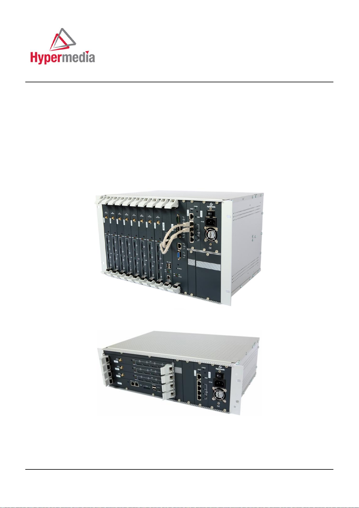
The Hypermedia Gateway unit is a 19" x 6U or 19" x 3U rack-mountable box that
connects to the local PBX or network via a PRI card or VoIP card. It also connects
to the cellular network via up to 8 cellular cards, each card with 4 modules of
cellular channels. The system enables any combination of connectivity between its
various interfaces.
1.1.1 Contents of Package
Depending upon configuration, the package should contain some or all of the
following:
The Hypermedia Gateway unit
Ethernet cables
1 or 2 power cords, depending upon the configuration
1 to 8 indoor antennas, depending upon the configuration
Hypermedia Software CD-ROM
The warranty certificate
1 SD card (standard gateway)
Hypermedia Systems Ltd.
2

Hypermedia System
Hardware and Installation
1.2 Safety Information
Hypermedia Gateway works with a nominal mains supply voltage of 110– 240V
AC. Hazardous voltages are present inside of this equipment. Some of the parts can
also have high operating temperatures.
To avoid injury and prevent equipment damage, observe the following safety
precautions:
Installation, service, and maintenance of the Hypermedia Gateway should be
done by qualified technicians only.
Do not connect the Hypermedia Gateway to any power source other than the
indicated nominal source.
The power supply cord must be connected to a socket with a valid ground. This
equipment should only be used in buildings with proper safety ground.
When connecting the equipment, first, ensure that the ground connection is
connected to the rack ground or building ground.
When disconnecting the equipment, disconnect the ground connection last.
Opening the housing may be dangerous and invalidates the warranty. Only a
qualified technician should open the housing. Before opening, disconnect the
power cable from the equipment.
The Hypermedia Gateway complies with all necessary safety standards.
Equipment connected to the Hypermedia Gateway must also comply with the
applicable safety standards.
The packaging is designed to protect against mechanical damage and should be
stored. Do not ship equipment unless it is properly packed in its original
wrapping and shipping containers.
Make sure that the equipment top and bottom are not blocked to air movement.
Leave 1U under and on top of the equipment for proper ventilation.
Do not operate the Hypermedia Gateway in close proximity to potentially
hazardous areas. These includes areas such as, but not exclusively, fuel stations,
fuel depots, chemical works or during blasting.
The operation of radio transmitters, which includes cellular engines, can impair
the function of medical devices that have not been properly shielded. Please ask
the advice of your doctor or the manufacturer of the medical device.
To avoid moisture condensation, allow time for the unit to adapt to the ambient
temperature before switching it on.
Release 5.3 (October 2013)
3

Hardware and Installation
System Components
1.3 System Components
The HG-4000 Gateway comes in two main series:
Standard — based on an embedded CPU and is designed for the enterprise user.
Heavy-Duty — based on a PC board and is designed for the VoIP call operator.
The Hypermedia Gateway is a 19" × 6U or 19" × 3U rack-mount unit that
connects to the local PBX or network. The system enables any combination of
connectivity between its PRI and cellular interfaces (VoIP and BRI are
optional).
The unit is built of a backplane and slots for the system boards, as described in
the following Table 1. The placement of the boards varies according to product
configuration.
The unit contains a single power supply module. A dual power supply module
is also available.
Depending upon system configuration, the Hypermedia Server is an application
that is embedded on the HBN, HBS, HBD or on the PC1/2 board. The
Hypermedia Server is controlled and managed by the browser-based
Hypermedia Management Console.
The Hypermedia Management Console (HMC) is used by the system
administrator for remote configuration and monitoring of the Hypermedia
Gateway system. It connects to the gateway using TCP/IP and is accessed via a
standard WEB browser.
Hypermedia Systems Ltd.
4

Hypermedia System
Board Name
Description
Standard Gateway's Boards
HBN, HBD, HBS
These Hybrid boards provide the gateway management
function as well as VoIP functionality. Optionally, these
cards can also support PRI functionality. The HBD supports
dual PRI ports and the HBS supports a single PRI port.
Heavy-Duty Gateway's Boards
PC1/PC2
The PC board runs the HyperGateway Server along with one
of the following boards: MC, SU or MG.
MC1.0, MC1.1, MC1.2
These boards provide support for VoIP functionality (MC1.0)
and the PRI connectivity function (MC1.1, MC1.2). Installed
on PC-based systems. The MC1.2 card supports dual PRI
ports and the MC1.1 card supports a single PRI port.
SU
This board provides support for VoIP functionality (32 ports)
in 3U form board along with MG2.1
MG 2.1
This board contains a media matrix, and is used with an SU
board.
MG1.2
This board provides support for VoIP functionality where 72
ports expansion is required. It also contains a media matrix.
Cross-Gateways Boards
CG41/CC41/CU41
CG41 for GSM, CC41 for CDMA and CU41 for UMTS is a
single-slot board that enables four (4) inbound and outbound
cellular voice calls for the various cellular networks.
RO 1.X
This is an embedded router board
S-HUB
This board provides SIM server connectivity
Hardware and Installation
1.4 Typical Board Configurations
The placement of the HG-4000 boards varies according to the product series. The
names and function of the boards is described in the following Table 1.
Table 1. HG-4000 Boards and Function
Release 5.3 (October 2013)
5
Hardware and Installation
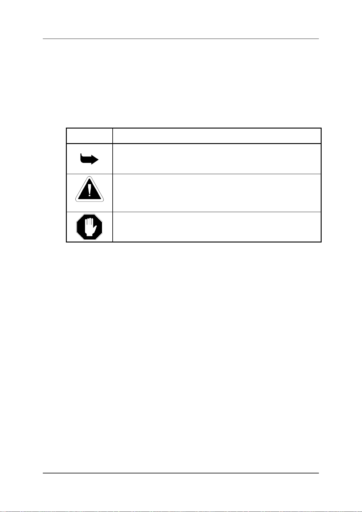
HBN Board
CG Boards
Power Supply
3U
Router Board
Power Supply
CG Boards
HBN Board
6U
Router Board
Typical Board Configurations
1.4.1 Standard Series
1.4.1.1 3U Standard Gateway, up to 12 ports, SIP or H.323
Figure 1. 3U Standard Gateway (up to 12 ports)
1.4.1.2 6U Standard Gateway, up to 32 ports, SIP
Figure 2. 6U Standard Gateway (up to 32 ports)
Hypermedia Systems Ltd.
6
Hypermedia System
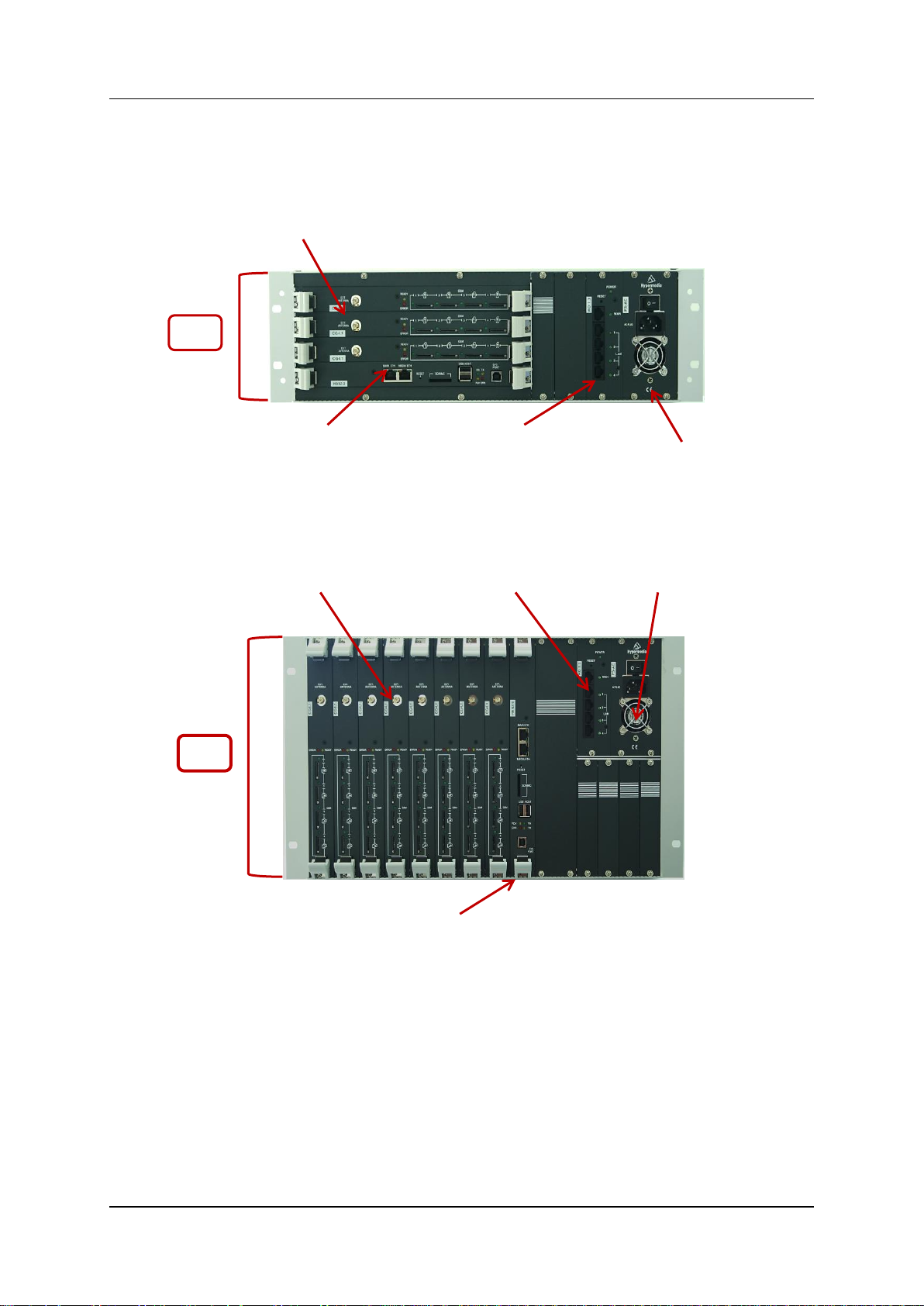
Power Supply
CG Boards
MC Board
6U
PC Board
Router Board
Power Supply
CG Boards
PC Card
6U
MG Board
Router Board
SU Board
Hardware and Installation
1.4.2 Heavy-Duty Series
1.4.2.1 6U Heavy-Duty, 32 ports – PC + MC, SIP or H.323
Figure 3. 6U Heavy-Duty (32 ports)
1.4.2.2 6U Heavy-Duty, up to 32 ports – PC +SU, SIP or H.323
Figure 4. 6U Heavy-Duty (up to 32 ports)
Release 5.3 (October 2013)
7
Hardware and Installation
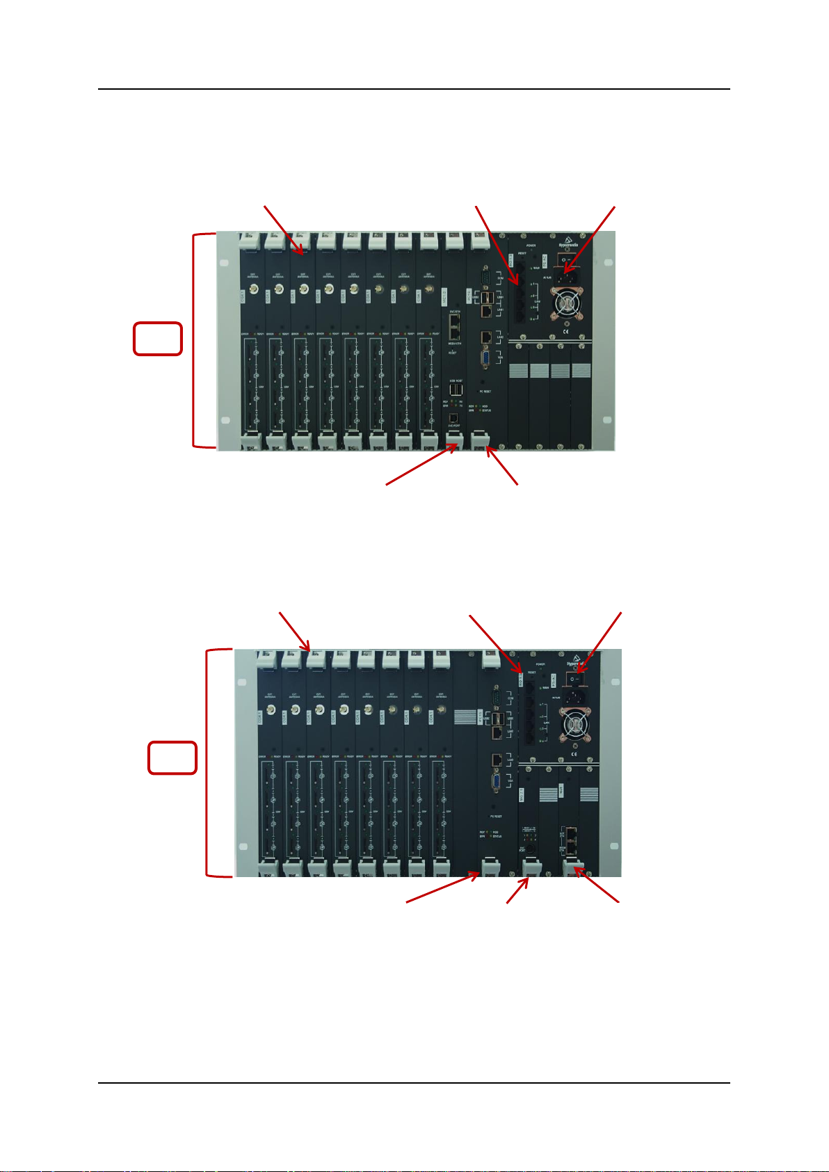
Power Supply
CG Boards
PC Card
6U
MG Board
Router Board
Typical Board Configurations
1.4.2.3 6U Heavy-Duty, expandable up to 72 ports – PC+MG, SIP or H.323
Figure 5. Heavy-Duty (expandable up to72 ports)
Hypermedia Systems Ltd.
8

Hypermedia System
Hardware and Installation
1.5 Installation
Note: Installation varies depending upon the boards included with the Hypermedia
Gateway system. Skip the sections that do not apply to your system.
1.5.1 Pre-Installation Preparations
1. Install the Hypermedia Gateway in a 19‖ rack. Depending upon the physical
configuration, the unit requires a height of either 3U or 6U. In addition, we
recommend: the following
Avoid installing the device near computer rooms, computer monitors,
electrical cabinets, metal objects, and windows with fold aluminum sheet.
Perform a cellular signal check before mounting the system. This can be
done by checking the Signal Strength and the Bit Error Rate ratio on another
mobile phone's display from the same operator and system.
Ensure that the device is protected against direct sunlight and heat. This
increases both the reliability of the operation as well as its service life.
The provided antennas are for indoor use only. RF combiners and external
antennas are sold separately.
The cables to the devices should be installed so that they do not cause any
physical risk. Power cables should be installed separate from the signal
cables.
2. Depending upon the configuration of your system, verify that you have some or
all of the following:
an Ethernet or WAN socket with a fixed IP address
a spare card in your PBX
SIM cards from your GSM operator. One SIM card is required for each
GSM channel
3. To configure the Router, get the following information from your Internet
Service Provider:
WAN IP Address
Subnet Mask, and WAN Gateway
Note:
The RO 1.X default LAN IP address for the Hybrid-Based Gateway is
192.168.9.254
The RO 1.X default LAN IP address for the PC-Based Gateway is
192.168.0.1
Release 5.3 (October 2013)
9

Hardware and Installation
Cable Connections
1.6 Cable Connections
There are two types of connections:
Standard Gateway – Hybrid based (HBN, HBS, HBD)
Heavy-Duty Gateway – PC Based (MC, MG+SU)
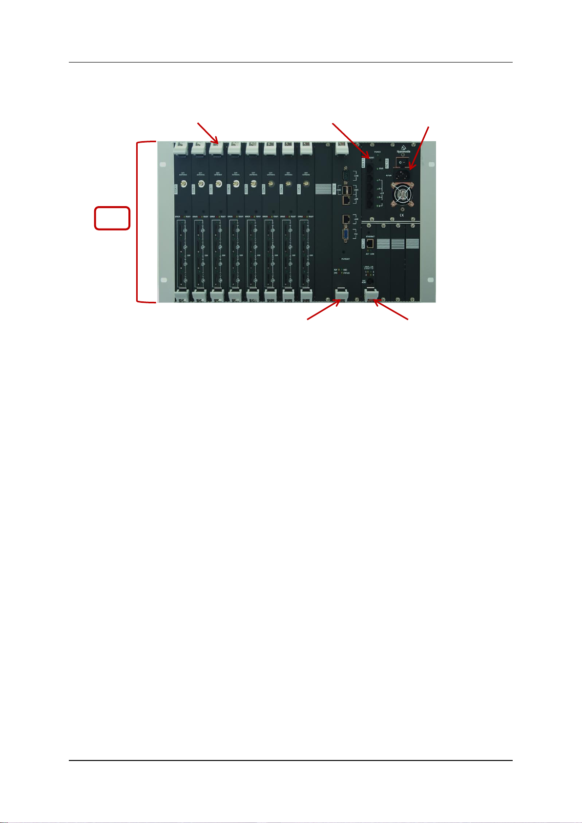
1.6.1 Standard Gateway - Hybrid Based (HBN, HBS and HBD)
Hypermedia Systems Ltd.
10
Figure 6. HG4000 - HBN Connection Settings
Hypermedia System
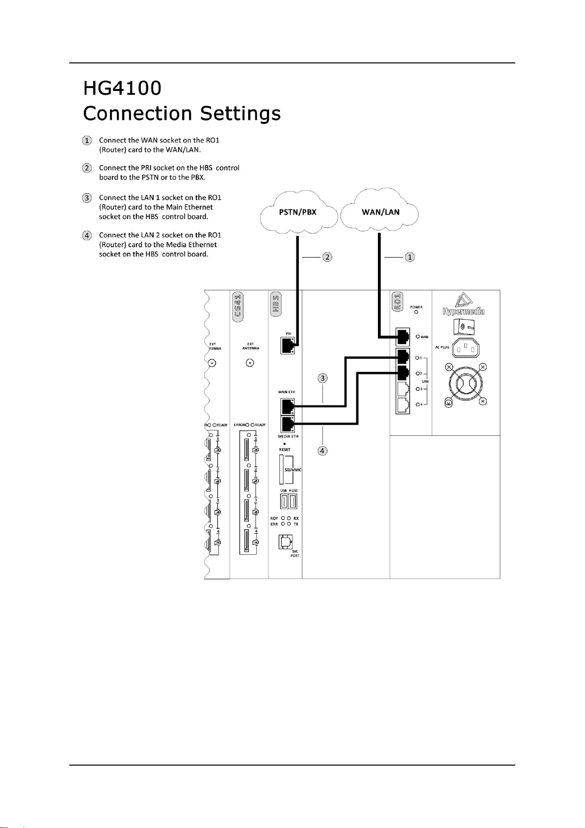
Hardware and Installation
Figure 7. HG-4100 - HBS Connection Settings
Release 5.3 (October 2013)
11
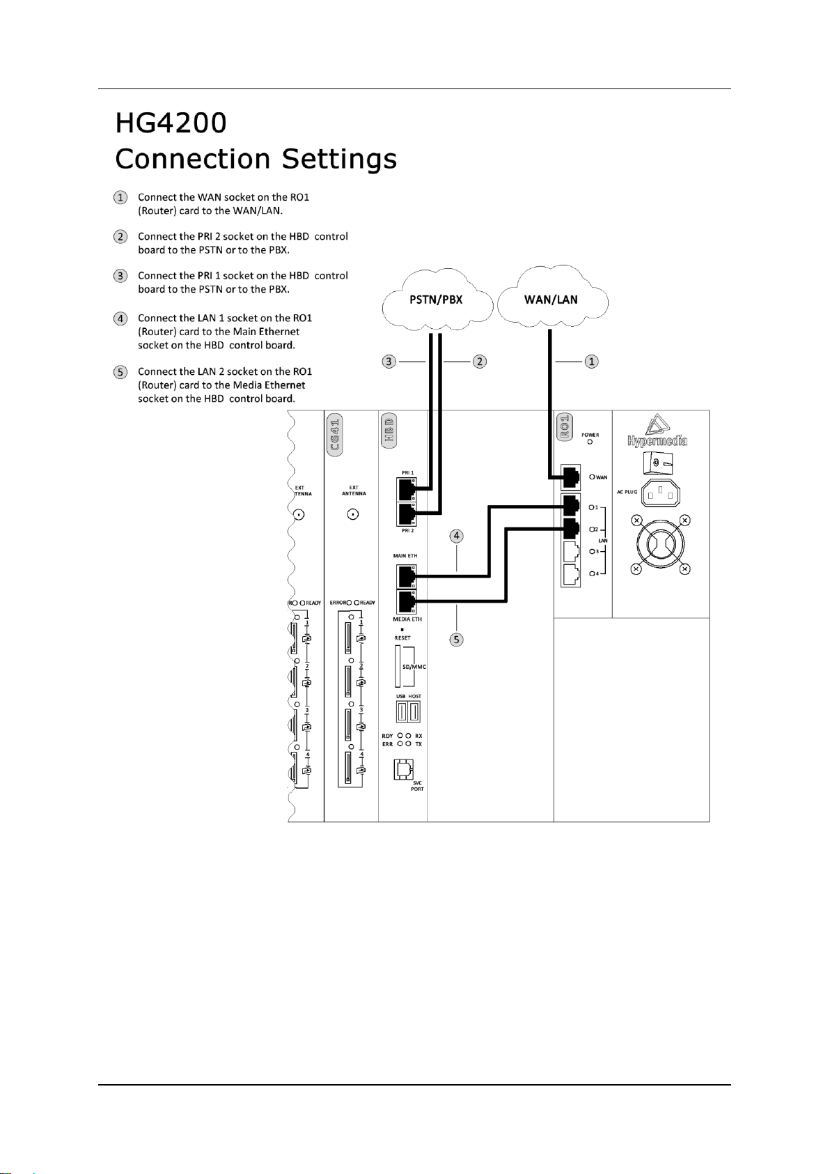
Hardware and Installation
Cable Connections
Figure 8. HG-4200 - HBD Connection Settings
Hypermedia Systems Ltd.
12
Hypermedia System
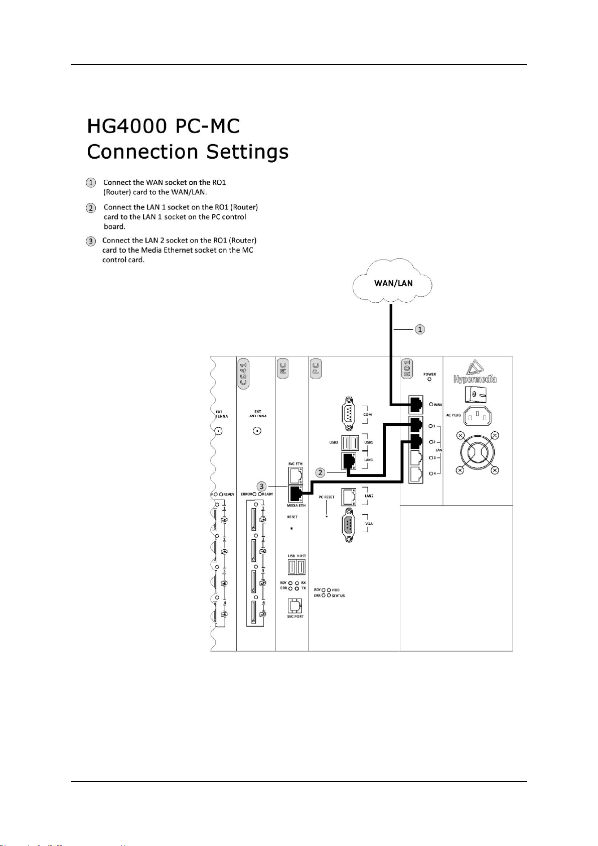
Hardware and Installation
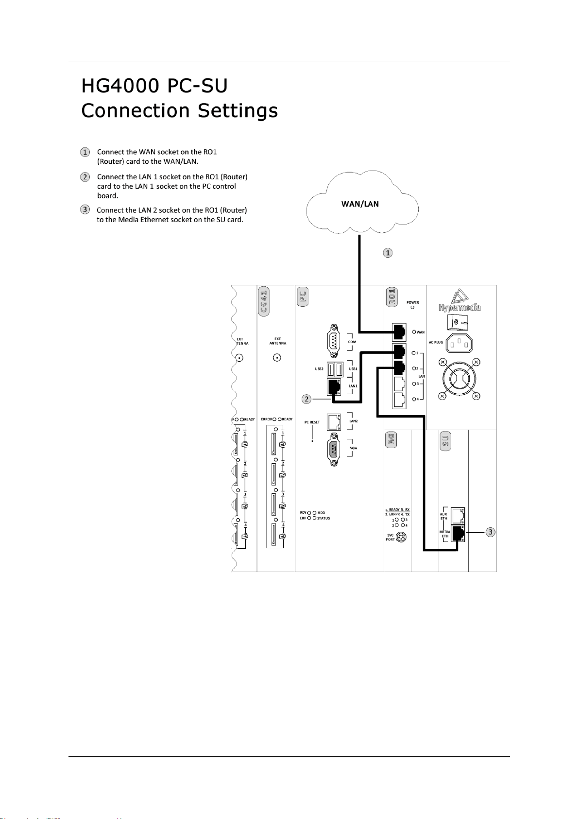
1.6.2 Heavy-Duty Gateway – PC Based (MC, MG+SU)
Figure 9. HG-4000 – PC-MC Connection Settings
Release 5.3 (October 2013)
13
Hardware and Installation
Cable Connections
Figure 10. HG-4000 – PC-SU+MG Connection Settings
Hypermedia Systems Ltd.
14
Hypermedia System
Hardware and Installation
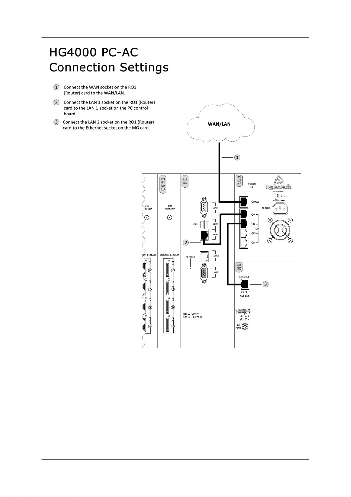
Figure 11. HG-4000 – PC + MG Connection Settings
Release 5.3 (October 2013)
15
Hardware and Installation
Cable Connections
1.6.3 Router Settings – RO 1.X
The RO 1.X board is an Ethernet Broadband Router with NAT network address
translation technology. It enables the Hypermedia Gateway to connect to a public IP
and to operate behind firewalls equipped with Network Address Translation (NAT).
Note: A router exists only on VoIP enabled gateway.
1.6.3.1 Standard Gateway (HBN, HBS, HBD) Router Setup
1.6.3.1.1 Assigning a Static WAN IP address (Public IP address)
Setting-up the RO 1.X board requires proper configuration of the computer network
settings. The default LAN IP address of the RO 1.X is 192.168.9.254 and the default
subnet mask is 255.255.255.0. These addresses cannot be changed. If changed,
connection with the Gateway will be lost.
If the TCP/IP environment of your computer has not yet been configured, refer to
configuring your PCs to connect to one of the free LAN ports of the RO 1.X board.
Configure your computers to automatically obtain TCP/IP settings from the DHCP
server embedded in the RO 1.X.
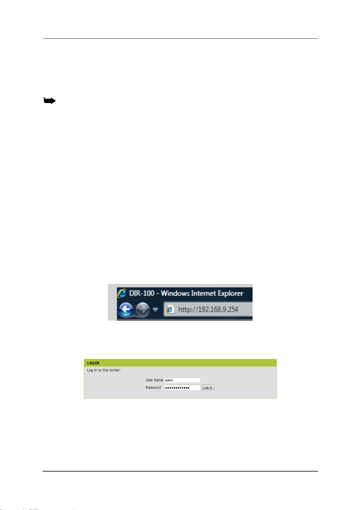
1.6.3.1.2 Start-up and Login
1. While connected to a free LAN port, activate your web browser and type in the
IP address of the RO 1.X / DIR-100 into the Address field and press ―Enter.‖
The default LAN IP address of the RO 1.X / DIR-100 is 192.168.9.254
2. After the connection is established, the logon screen opens. To log in as an
administrator, enter the username of ―admin‖ and the password
―hypergateway".
3. Click the Log In button. The Setup Wizard screen appears.
Hypermedia Systems Ltd.
16

Hypermedia System
Hardware and Installation
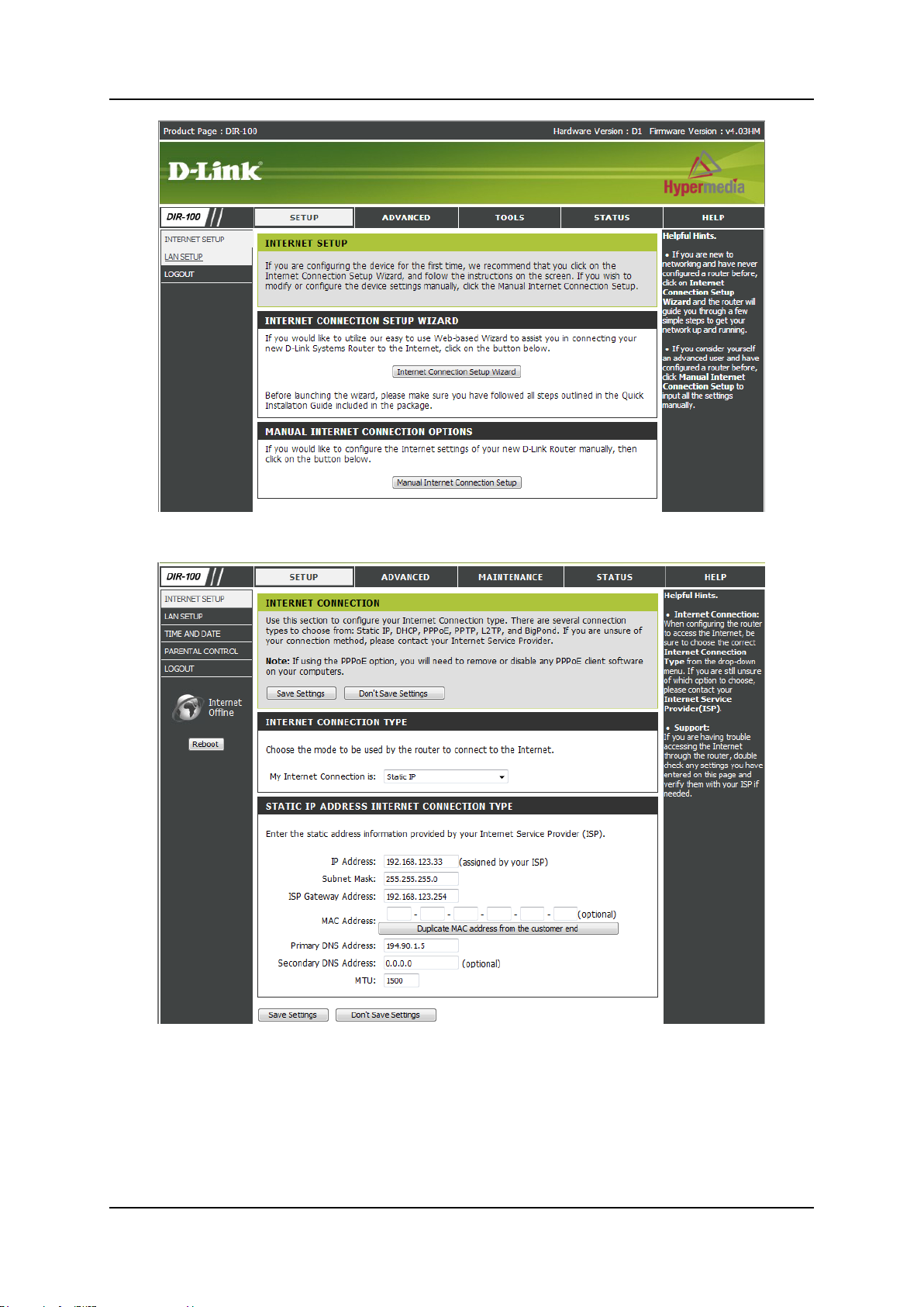
4. Click on Manual Internet Connection Setup. The following screen appears.
5. Fill in the Public IP address information provided by your ISP.
6. Fill in the Subnet Mask, ISP Gateway address and Primary DNS address
(optional).
7. Click Save Settings.
Release 5.3 (October 2013)
17
Hardware and Installation
Cable Connections
1.6.3.2 Heavy-Duty Gateway (PC Based) Router Setup
1.6.3.2.1 Assigning a Static IP address (Public IP address)
Setting-up the RO 1.X board requires proper configuration of the computer network
settings. The default LAN IP address of the RO 1.X is 192.168.0.1 and the default
subnet mask is 255.255.255.0. These addresses cannot be changed. If changed,
connection with Gateway will be lost and the default values are used in this manual.
If the TCP/IP environment of your computer has not yet been configured, refer to
configuring your PCs to connect to one of the free LAN ports of RO 1.X board.
Configure your computers to automatically obtain TCP/IP settings from the DHCP
server embedded in the RO 1.X.
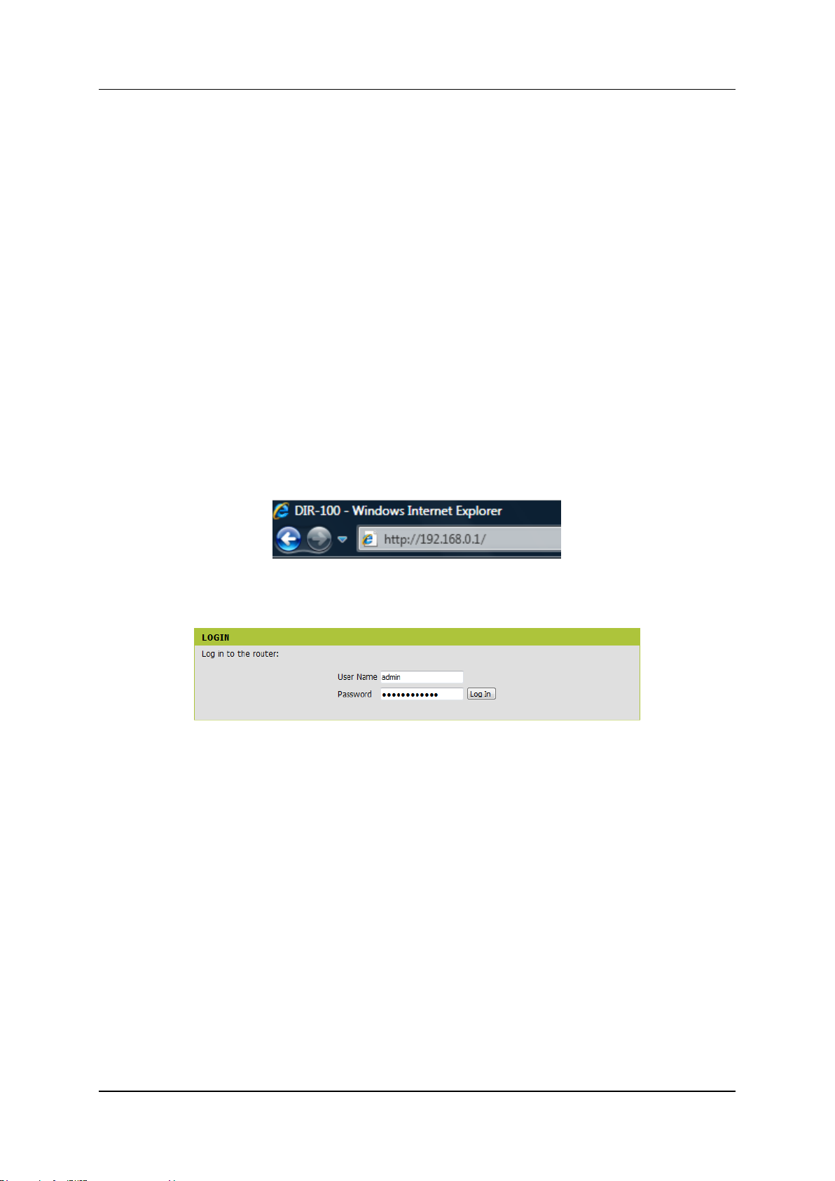
1.6.3.2.2 Start-up and Login
1. While connected to a free LAN port, activate your web browser and type in the
IP address of the RO 1.X into the Address field and press ―Enter.‖ The default
IP address of the RO 1.X is 192.168.0.1.
2. After the connection is established, the logon screen appears. To log in as an
administrator, enter the username ―admin‖ and the password ―hypergateway".
3. Click the Log In button. The Setup Wizard screen appears.
Hypermedia Systems Ltd.
18
Hypermedia System
Hardware and Installation
4. Click on Manual Internet Connection Setup. The following page appears.
5. Fill in the Public IP address information provided by your ISP.
6. Fill in the Subnet Mask, ISP Gateway address and Primary DNS address
(optional).
7. Click Save Settings.
Release 5.3 (October 2013)
19
Hardware and Installation
SIM Card
SIM Drawer
Yellow button for drawer
Multi-SIM
Extender
Antenna Socket
Inserting the SIM Cards and Antennas
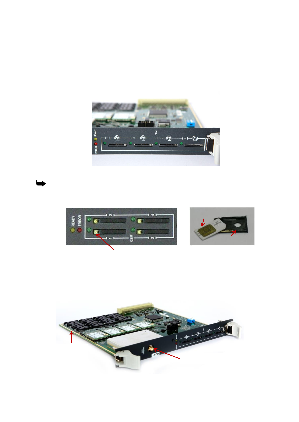
1.7 Inserting the SIM Cards and Antennas
1. Insert the GSM SIM Cards. One SIM card for each cellular channel.
The front SIM ports are spring loaded. Slide the SIM card into the slot until it is
held in place. Press the SIM card until it pops out to remove.
Figure 12. SIM Card Slots
Note: Some versions of the CG board have SIM drawers. Push the small yellow button for
the SIM drawer to exit. Remove the SIM drawer, place the SIM card in the SIM drawer and
replace the SIM drawer.
Figure 13. SIM Drawers
If more than four cellular channels are used, insert the additional required SIM
cards into the CG board‘s multi-SIM extender:
a. Pull out the CG board.
Hypermedia Systems Ltd.
20
Figure 14. CG Card with a 12 Multi-SIM Extender
 Loading...