

Page 1

Hyperlink Extended Range WLAN Kit Installation Manual Rev. A Page 1
Hyperlink WaveLAN
Extended Range Wireless LAN Kit
Featuring Lucent Technologies WaveLAN Technology
Installation Manual
NOTE: The antenna system shall be installed ONLY by experienced antenna
installers who are familiar with local building and safety codes, and
wherever necessary have been licensed by appropriate government
regulatory bodies. Failure to do so may void the Product Warranty, as well
as expose the end-user to legal and/or financial liabilities. Hyperlink
Technologies, its agents, resellers or distributors, are not liable for injury,
damage, or violation of government regulations that may arise from failing
to comply with the guidelines described in this document.
Hyperlink Technologies, Inc.
Page 2

Hyperlink Extended Range WLAN Kit Installation Manual Rev. A Page 2
Disclaimer: The diagrams used in this manual are for illustrative purposes only.
They should not be confused with the PC card operating in standalone mode. When
these diagrams are used the PC card transceiver will be installed in conjunction with
the specific DC Injector/Lightning Protector, Amplifier, cables and antennas listed in
this manual.
Copyright © 2000, Hyperlink Technologies, Inc.. All rights reserved. No part of the
contents of this document may be transmitted or reproduced in any form or by any
means without the written permission of Hyperlink Technologies, Inc.
Portions Copyright © Lucent Technologies, Inc. All rights reserved
HyperGain and HyperAmp are trademarks of Hyperlink Technologies, Inc.
WaveLAN, WavePOINT and Orinoco are registered trademarks of Lucent
Technologies, Inc.
Hyperlink Technologies, Inc.
Page 3

Hyperlink Extended Range WLAN Kit Installation Manual Rev. A Page 3
Contents
FCC Radio Interference Statement 4
Radiation and EIRP Information 5
Introduction 6
System Features 6
Types of Installations 7
System Requirements 8
Kit Contents 8
Tools Required 8
WaveLAN Card Features 8
Overall System Configuration 9
Antenna System Connection 10
Surveying the Antenna Site 10
Preparing for System Installation 11
Connections & Features of the Amplifier 12
The DC Power Injector/Lightning Protector 13
Mounting & Cabling the Amplified Antenna System 14
Installing the WaveLAN PC Card 16
Channel Settings 16
Basic System Checks 17
WaveLAN Antenna Alignment Diagnostics 17
System Specifications 18
APPENDICES
Antenna Mounting Instructions Appendix A
Hyperlink Technologies, Inc.
Page 4

Hyperlink Extended Range WLAN Kit Installation Manual Rev. A Page 4
USA- Federal Communications Commission (FCC)
Interference Statement
This device complies with Part 15 of the FCC Rules. Operation is subject to the
following two conditions: (1) this device may not cause harmful interference, and (2)
this device must accept any interference received, including interference that may
cause undesired operation.
Information to the user
NOTE: This equipment has been tested and found to comply with the limits for a
Class B digital device, pursuant to Part 15 of the FCC Rules. These limits are
designed to provide reasonable protection against harmful interference in a
residential installation. This equipment generates, uses, and can radiate radio
frequency energy. If not installed and used in accordance with the instructions, it
may cause harmful interference to radio communications. However, there is no
guarantee that interference will not occur in a particular installation. If this equipment
does cause harmful interference to radio or television reception, which can be
determined by turning the equipment off and on, the user is encouraged to try and
correct the interference by one or more of the following measures:
• Reorient or relocate the receiving antenna.
• Increase the distance between the equipment and the receiver.
• Connect the equipment to an outlet on a circuit different from that to which the
receiver is connected.
• Consult the dealer or an experienced radio/TV technician for help.
Any changes or modifications of equipment not expressly approved by the
manufacturer could void the user’s authority to operate the equipment and the
company’s warranty.
NOTE: The antenna system shall be installed ONLY by experienced antenna
installers who are familiar with local building and safety codes, and
wherever necessary have been licensed by appropriate government
regulatory bodies. Failure to do so may void the Product Warranty, as well
as expose the end-user to legal and/or financial liabilities. Hyperlink
Technologies, its agents, resellers or distributors, are not liable for injury,
damage, or violation of government regulations that may arise from failing
to comply with the guidelines described in this document.
Hyperlink Technologies, Inc.
Page 5

Hyperlink Extended Range WLAN Kit Installation Manual Rev. A Page 5
Caution: Exposure to Radio Frequency Radiation.
The radiated output power of this product is below the FCC radio exposure limits.
Nevertheless, this product shall be used in such a manner that the potential for
human contact during normal operation is minimized.
Antenna shall be mounted in such a manner as to minimize the potential for
human contact during normal operation. In order to avoid the possibility of
exceeding the FCC radio frequency exposure limits, human proximity to the
antenna shall not be less than 20 cm (8 inches) during normal operation.
Hyperlink Technologies is not responsible for any radio or television interference
caused by unauthorized modification of this device or the substitution or attachment
of connecting cables and equipment other than specified by Hyperlink
Technologies. The correction of interference caused by such unauthorized
modification, substitution or attachment will be the responsibility of the user.
Antenna
Type
HG2408P 7.5 24 31.5 10.6
HG2408U 8.0 24 32.0 11.2
HG2412P 12.0 20 32.2 11.5
HG2415Y 14.5 20 34.7 15.3
HG2415U 15.0 20 35.2 16.2
HG2415G 15.0 20 35.2 16.2
HG2419G 19.0 17 36.0 17.8
HG2424G 23.5 11 35.1 16.0
WARNING: It is the respons ibility of the professional installer to ensure that when
using the outdoor antenna kits in the United States (or where the FCC rules apply),
only these antenna configurations shown in the table above and which are
described in this document are used. The use of any other than those listed is
expressly forbidden in accordance to FCC rules CFR47 part 15.204.
Specified
Antenna Gain
(dBi)
Maximum Output
Power at Antenna
Terminal (dBm)
Total EIRP
(dBm)
Minimum RF
Exposure
Separation
Distance (cm)
Hyperlink Technologies, Inc.
Page 6

Hyperlink Extended Range WLAN Kit Installation Manual Rev. A Page 6
Introduction
The Hyperlink Extended Range Wireless LAN Kit is a direct sequence spread
spectrum wireless transceiver providing 11 Mbit/sec data rate to support wireless
connections in an IEEE 802.3 LAN. Equipped with a Hyperlink Extended Range
Amplified Antenna System, this product offers a high-performance long-range
building-to-building wir eless networking solution.
This kit incorporates Lucent Technologies WaveLAN technology. WaveLAN uses a
state-of-the-art direct sequence spread spectrum technology to implement robust
11 Mbps transmission, and offers true “Plug and Play ” installation.
System Features:
This system has the following features:
• IEEE 802.11 Compatibility.
• Wireless 11 Mbps data rate.
• State-of-the-art spread spectrum technology provides
reliable, secure, long range, radio link operation.
• True “Plug and Play” installation for compatibility with all
802.3 and Ethernet II LAN devices, all operating systems
and all protocol stacks.
• PCMCIA Form Factor
• User-selectable channels of operation.
• Remote mounted bi-directional amplifier to optimize
transmit powe r and eliminate the effects of system cable
losses.
• Limited 2 year Warranty.
Hyperlink Technologies, Inc.
Page 7
Hyperlink Extended Range WLAN Kit Installation Manual Rev. A Page 7
Types of Installations
The type of application will determine which type of kit to install:
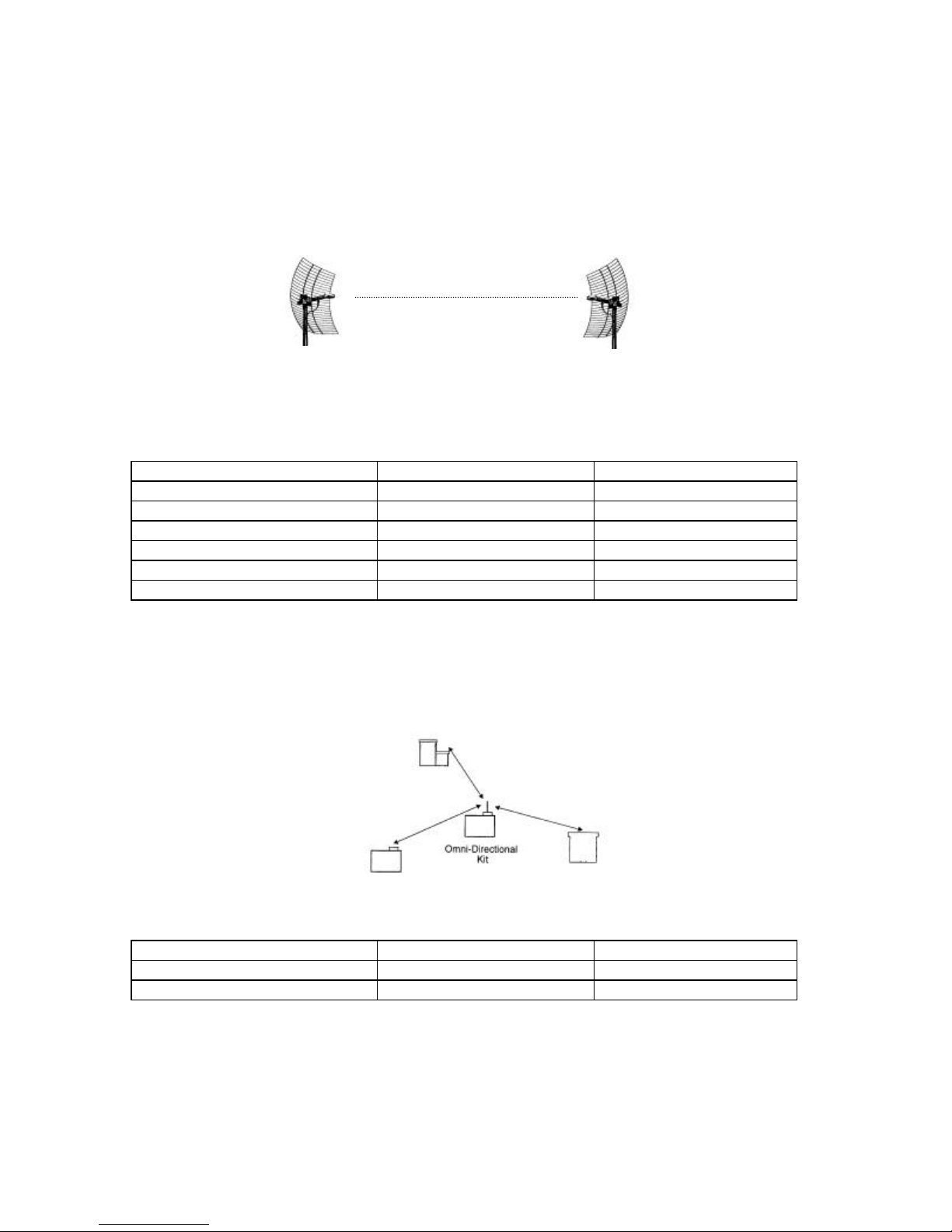
1. Fixed Point-to-Point (Building-to-Building or Tower-to-Tower): Typically
these installations will typically require directional Yagi, Panel or Grid Antenna kits.
These devices are authorized for operation in fixed, point-to-point
configurations only. The professional installer is responsible for
ensuring that the system is used exclusively for fixed, point-to-point
operations.
ANTENNA MODEL ANTENNA GAIN TYPE
HG2408P 8 dB i DIRECTIONAL PATCH
HG2412P 12 dBi DIRECTIONAL PANEL
HG2415G 15 dBi DIRECTIONAL GRID
HG2415Y 14.5 dBi DIRECTIONAL YAGI
HG2419G 19 dBi DIRECTIONAL GRID
HG2424G 23.5 dBi DIRECTIONAL GRID
2. Central Node in a Multipoint Network or Mobile Network: This type of
installation typically requires an Omni Directional Kit at the central node for 360
degree coverage.
ANTENNA MODEL ANTENNA GAIN TYPE
HG2408U 8 dB i OMNIDIRECTIONAL
HG2415U 15 dBi OMNIDIRECTIONAL
Hyperlink Technologies, Inc.
Page 8

Hyperlink Extended Range WLAN Kit Installation Manual Rev. A Page 8
System Requirements
The WaveLAN/HyperGain™ Amplified Extended Range Bridge Kit provides a
complete plug-and-play solution for linking buildings in an outdoor environment.
The PC card included can be installed in any one of the following devices:
Lucent Orinoco Central or Remote Office Router Processor
KarlNet Central or Satellite Router Processor
Other compatible PC, Router, or Bridge Processor equipped with a PC Card slot
Besides one of the host processors above, all you need to add is suitable masts
or towers and some basic site planning. Please read this manual in its entirety
before beginning the installation.
Kit Contents:
Each Kit contains the following items:
WaveLAN/Orinoco Turbo 11 Mbit IEEE 802.11 PC Card
HyperAmp Remote Mounted Amplifier
HyperGain Antenna (Omn i, Yagi, Panel or Grid)
HyperGain DC Power Injector/Lightning Protector
50 ft. Antenna Cable
0.5 meter Jumper Cable
Mounting Hardware
Manual
Tools Required:
Assorted open -end or adjustable wrenches
#12-10 AWG or similar wire (for grounding)
Wire cutter / stripper
Pliers
Other Required Equipment:
Suitable mast or tower hardware
Other Helpful Equipment and Tools:
Cellular telephones or Walkie-talkies
Binoculars
Compass
Handheld GPS
Hyperlink Technologies, Inc.
Page 9
Hyperlink Extended Range WLAN Kit Installation Manual Rev. A Page 9
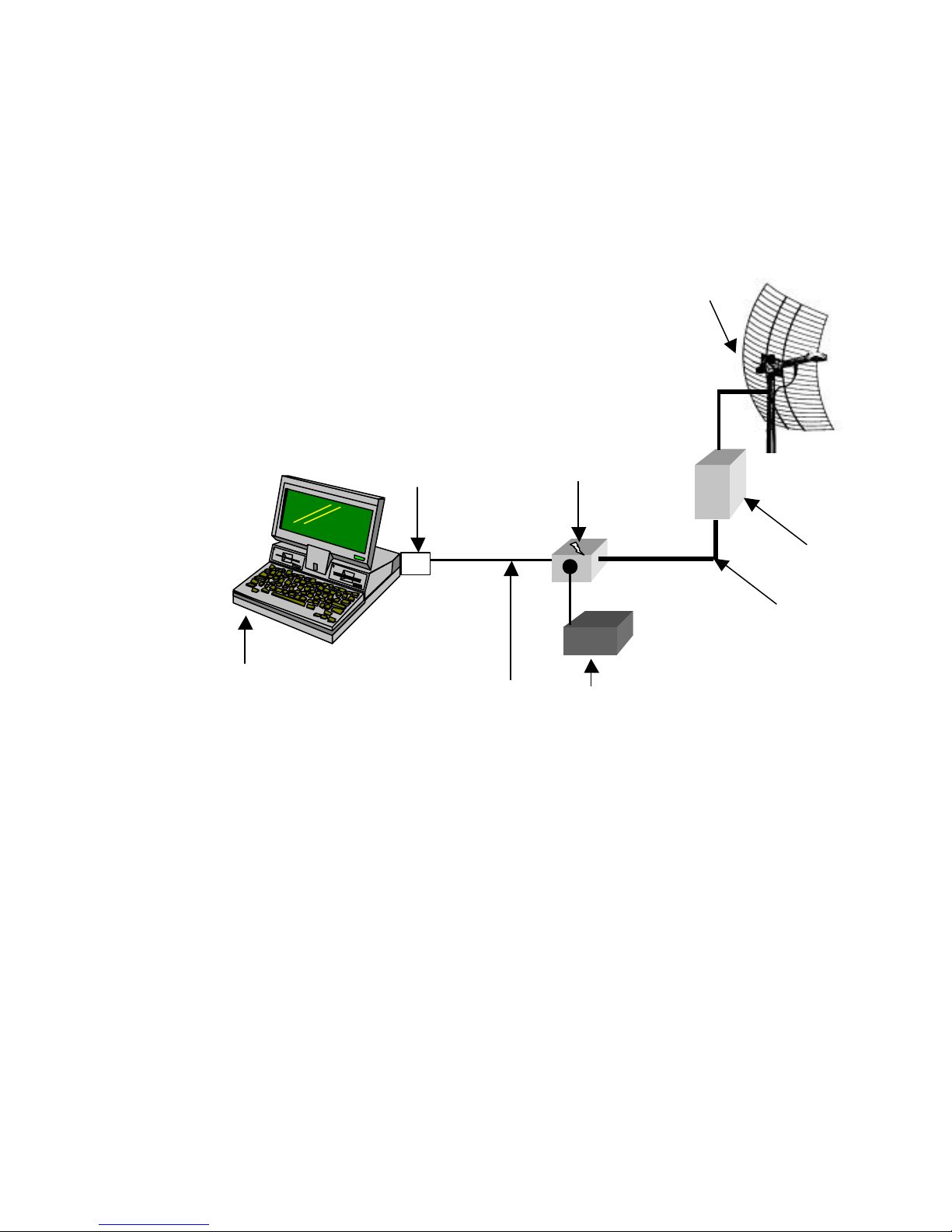
WaveLAN
Adapter
DC Power
Antenna
Network
DC Power
Overall System Configuration
The overall system configuration is shown below. Refer to this diagram while
reading the section which follows, and during system installation.
Antenna
PC Card
Workstation,
WavePOINT -II
Processor or
other Bridge Unit
Cable 0.5
meter
Injector
Amplifier
Cable 50ft.
Supp ly
Hyperlink Technologies, Inc.
Page 10

Hyperlink Extended Range WLAN Kit Installation Manual Rev. A Page
10
ANTENNA SYSTEM CONNECTION
NOTE: THE ANTENNA SYSTEM SHALL BE INSTALLED ONLY BY
EXPERIENCED ANTENNA INSTALLERS WHO ARE FAMILIAR WITH LOCAL
BUILDING AND SAFETY CODES, AND WHEREVER NECESSARY HAVE
BEEN LICENSED BY APPROPRIATE GOVERNMENT REGULATORY
BODIES. FAILURE TO DO SO MAY VOID THE PRODUCT WARRANTY, AS
WELL AS EXPOSE THE END-USER TO LEGAL AND/OR FINANCIAL
LIABILITIES. HYPERLINK TECHNOLOGIES, ITS AGENTS, RESELLERS OR
DISTRIBUTORS, ARE NOT LIABLE FOR INJURY, DAMAGE, OR VIOLATION
OF GOVERNMENT REGULATIONS THAT MAY ARISE FROM FAILING TO
COMPLY WITH THE GUIDELINES DESCRIBED IN THIS DOCUMENT.
Surveying the Antenna Site
Before beginning system installation, emphasis should be placed on system
planning. It is important that no large obstructions exist near the antenna, such as
retaining walls, chimneys, air-conditioning units or other antenna masts. These
types of objects can have an impact on the antenna system performance.
Plan to mount the antenna as high as possible. You will need enough mast to
elevate the antenna approximately 10-15 feet above the roof or above any
obstruction that might be in the antenna's signal path.
You will need to identify the location where the antenna cable will be routed. If you
run the antenna cable through the roof, a water-proof fitting will be required. Consult
a building contractor or licensed electrician to help you with the routing if necessary.
Take note of the length of the mast you will need and the type of mounting hardware
required. The amplified antenna kit is shipped with U-Bolt mounting hardware which
should be ideal for mounting the antenna and amplifier to most types of mast. Also,
make plans on how you are going to talk to the person at the remote antenna while
you are going through the antenna alignment procedure. For example, cellular
phones or walkie-talkies can be used.
Hyperlink Technologies, Inc.
Page 11

Hyperlink Extended Range WLAN Kit Installation Manual Rev. A Page
11
Preparing for System Installation
Warning: These antennas are designed to be mounted in open areas such
as rooftops or building exterior walls. They are designed to be installed at
least 6 feet away from areas occupied by people. During system operation,
always keep the antenna at least 1 foot away from your head.
Warning: Before performing the following steps make certain that there are
not any power lines within 50 ft. If the mast should fall, either while installing
or during operation, contact with any power lines will be fatal or result in a
fire.
The Antennas are designed to be mounted on an aluminum or steel mast with a
diameter from 1-1/4 inches to 3 inches. A larger diameter mast would be
suggested for a more durable installation. This system includes a 50 foot
antenna cable.
In addition to the kit contents, you will need a ground wire and wire ties.
Hyperlink Technologies, Inc.
Page 12
Hyperlink Extended Range WLAN Kit Installation Manual Rev. A Page
12
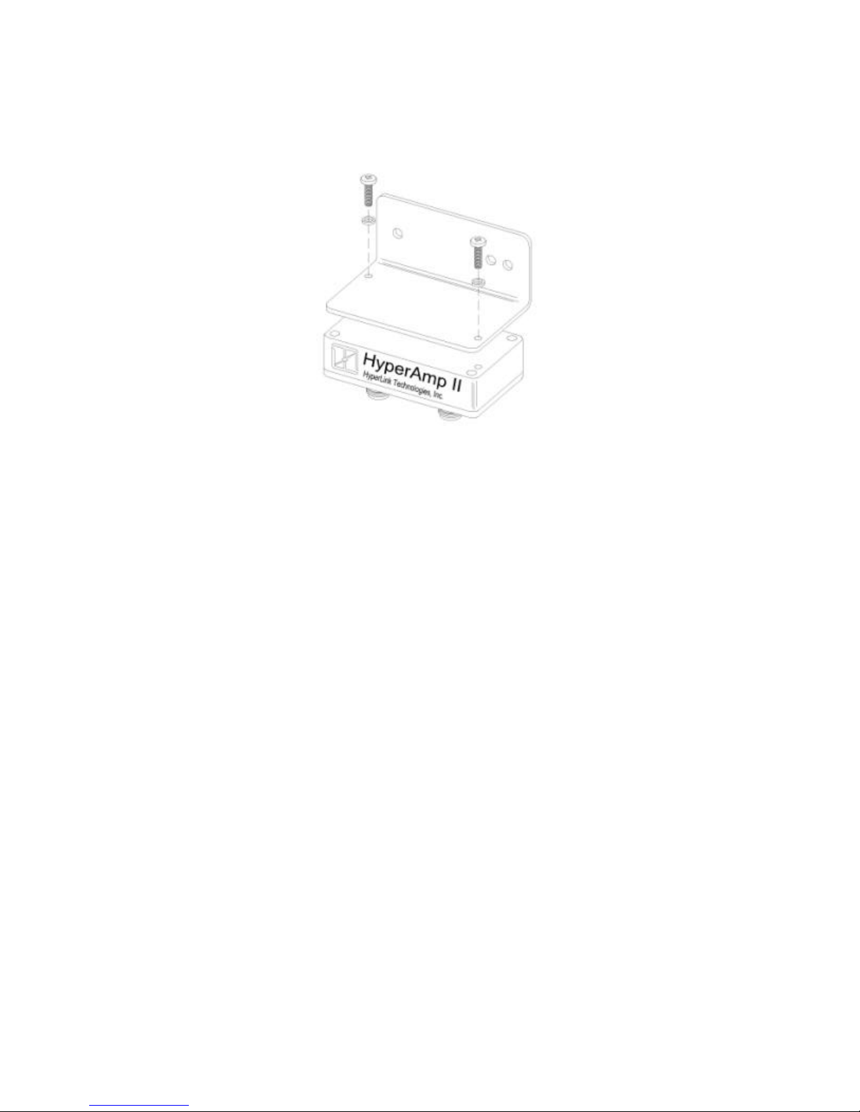
Installing the Amplifier Bracket for mast -mounting:
Install the right angle bracket as shown above using two (2) #10-24 screws and split
lockwashers as shown. Note the orientation of the label relative to the 90 degree
bend in the bracket. Proper positioning will ensure better visibility of the indicator
LEDs when installed on the mast.
Connections and Features of the Amplifier
Receive Indicator LED:
This LED illuminates green in receive mode.
Power Indicator LED:
This LED illuminates red in transmit mode.
Radio Connection:
This connection attaches to the DC Power Injector via the antenna feed cable, and
provides both signal and DC coupled power.
Hyperlink Technologies, Inc.
Page 13
Hyperlink Extended Range WLAN Kit Installation Manual Rev. A Page
13
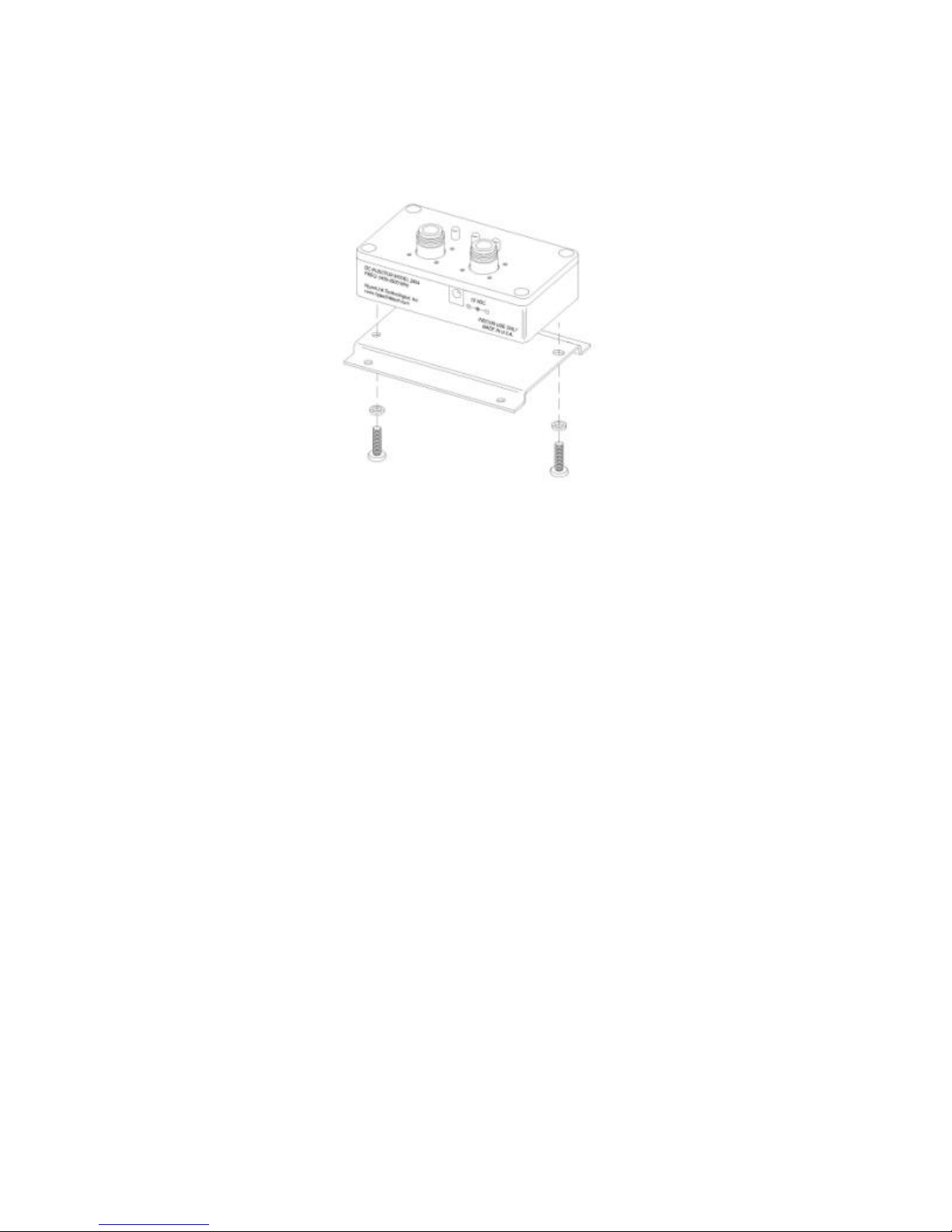
Installing the DC Injector Mounting Bracket:
Install the bracket as shown above using two (2) #10-24 screws and split
lockwashers as shown. For optimal lightning protection, it is recommended that one
screw also be used for attachment of a suitable ground wire.
Connections and Features of The DC Power Injector/ Lightning Protector
The DC Power Injector (also known as a "Bias-T") is an in -line device which
couples DC power onto a coaxial cable, enabling the cable to carry both RF (radio
frequency) signals and DC power. The amplifier is powered remotely through the
coaxial antenna feed cable by the way of this device. The DC Power Injector
included with the kit also provides integral lightning protection.
In addition to a POWER indicator LED, the DC Power Injector provides Remote
Receive and Transmit Detect indicator LEDs. The Power LED indicates that the
DC Power Supply is functioning. The Remote Receive and Transmit Detect
indicator LED detect changes in the DC current traveling through the antenna feed
cable supplying the amplifier. When the amplifier enters the receive mode the
Receive indicator will illuminate. When the amplifier enters the transmit mode the
Receive LED is extinguished and the Transmit LED will be illuminated. This
provides positive indication that the amplifier is functioning properly.
Hyperlink Technologies, Inc.
Page 14

Hyperlink Extended Range WLAN Kit Installation Manual Rev. A Page
14
Mounting and Cabling the Amplified Antenna System:
Note: Different model antenna kits have different mounting requirements and
procedures. Refer to Appendix A in this manual for antenna mounting details.
1. Attach the mast mounting hardware to a solid structure on your building (e.g.,
the roof itself, concrete bulkhead, vent pipe).
2. Using the included mounting hardware, secure the antenna to the top section of
the mast (see Appendix A for details) and similarly, install the amplifier directly
beneath the antenna using the included V-bolts.
3. Attach one end of the 50 ft. cable to the connector labeled “TO DC INJECTOR”
on the amplifier. Then connect the antenna to the connector labeled “TO
ANTENNA” on the amplifier.
4. Apply sealant tape around the joined connectors to prevent corrosion from the
weather. Wrap the entire connection, overlapping each layer slightly to ensure a
weather-tight seal.
5. Ground the antenna by connecting a suitable ground cable between the an tenna
mounting bracket and the building ground.
6. Very carefully raise the mast and loosely secure it with the mast mounting
hardware. Use the plastic wire ties to tie the antenna cable to the mast every
six to twelve inches.
7. Aim the directional antenna in the direction of the building you will be linked to.
The omni -directional antennas should be mounted vertically and do not need to
be aimed as they radiate in a 360 degree pattern.
8. Tighten the mast mounting screws. Do not do anything that would make it
difficult to change the position of the antenna. It may be necessary to reposition
the antennas while aiming them.
9. Route the antenna cable along the roof to the point where it enters the building.
From the inside, pull the cable through the hole and take up any excess slack.
Hyperlink Technologies, Inc.
Page 15

Hyperlink Extended Range WLAN Kit Installation Manual Rev. A Page
15
10. The DC Power Injector and Power Supply must be installed indoors near the
radio. The Injector unit can be wall-mounted using the included bracket if
desired. Attach the end of the 50 ft. antenna cable to the “TO AMPLIFIER”
connector on the DC Power Injector/Lightning Protector. Attach the 0.5 meter
adapter cable between the DC Power Injector’s “TO RADIO” connector and the
WaveLAN card.
11. Attach a ground wire to the ground lug on the DC Power Injector/Lightning
Protector and to a good building ground.
12. First, plug the 12 VDC power supply into the DC Power injector and then into
the building’s AC power. Never use a power supply other than the one shipped
with the system as it may cause damage to the radio and/or amplifier. It is
further recommended that the AC connections be made through a commercially
available "surge" protector power strip.
Hyperlink Technologies, Inc.
Page 16

Hyperlink Extended Range WLAN Kit Installation Manual Rev. A Page
16
Installing the PC Card
The method for installing the WaveLAN PC card depends upon the type of host
processor used. Follow the basic hardware installation instructions which came
with the host processor for installing PC cards.
When the PC card basic hardware installation is complete the card can be
configured using the WaveLAN PC card configuration utilities software.
Channel Settings
The Hyperlink Extended Range WaveLAN System is approved for operation in
seven (7) different operating frequency channels. These seven channels are a sub set of the eleven standard IEEE 802.11 channels.
NOTE: This equipment is not authorized for and may not be operated on IEEE
channels 1, 2, 10, and 11. If you wish to interoperate with other IEEE 802.11
WaveLAN-compatible equipment be sure to set that equipment to one of the seven
channels (A-G) shown in the table below:
Channel Corresponding
IEEE 802.11 Channel
NOT USED 1 2412
NOT USED 2 2417
A 3 2422
B 4 2427
C 5 2432
D 6 2437
E 7 2442
F 8 2447
G 9 2452
NOT USED 10 2457
NOT USED 11 2462
Once the channel selection has been made proceed with Basic System Checks
and Antenna Alignment procedures which follow.
Channel Center
Frequency
Hyperlink Technologies, Inc.
Page 17

Hyperlink Extended Range WLAN Kit Installation Manual Rev. A Page
17
Basic System Operational Checks
Using the system’s diagnostic LEDs, some basic system checks can now be
performed. When power is applied to the DC Injector the POWER and RECEIVE
indicators should illuminate green. In addition, the POWER/RECEIVE indicator will
illuminate green on the remote amplifier unit.
When the system is transmitting and receiving data the TRANSMIT to RECEIVE
indicator LEDs flash on and off. The POWER LED remains constant.
Note that the LED indicators may be difficult to recognize in bright sunlight.
WaveLAN Antenna Alignment Diagnostics
While many short-haul links can be installed simply by performing a visual antenna
alignment, in order to ensure that optimal antenna alignment is achieved it is
recommended that the installer run the WaveLAN link diagnostic software. This is
part of the WaveManager Client software which is included on the drivers disk. If
you are not already familiar with the diagnostic utilities please refer to the
WaveManager Client instructions for details.
Once optimal alignment has been achieved be sure to secure all cables,
connections and mounting hardware.
Hyperlink Technologies, Inc.
Page 18

Hyperlink Extended Range WLAN Kit Installation Manual Rev. A Page
18
Specifications
Frequency Range: 2400-2483.5 MHz ISM band
Operating Ch annel 2422, 2427, 2432, 2437
Center Frequencies 2442, 2447, 2452
Modulation Type: Direct Sequence Spread Spectrum
Communication Method: Half Duplex
Channel Access Method: CSMA/CA
Type of Interface: PCMCIA
Operating Temperature: 0 ~ +40 C
Storage Temperature: -20 ~ +60 C
Humidity: 0% ~ 90%
Hyperlink Technologies, Inc.
 Loading...