

Page 1

Emeter v2 Quick Guide 2.09 rev. Feb 9 2009
See http://media.hyperion.hk/dn/em2 for updates to documentation, PC software, and Firmware
Introduction
The Hyperion Emeter II can carry out an enormous range of functions related to Electric Powered models and
small vehicles, and has been designed with ease of use as a prime objective. On-screen help, a menu system
and friendly error messages all contribute to this objective while in the field or at the lab.
This Quick Guide describes the scope of Emeter II and how to make it work for you, in a sequence which
matches the on-screen menus. The Emeter’s own On-screen help is a subset of this information intended to
answer most questions at the field. The full Emeter II User Manual (Download from link above) goes into
greater depth with explanations of many of the issues surrounding Electric Power and Radio Control models.
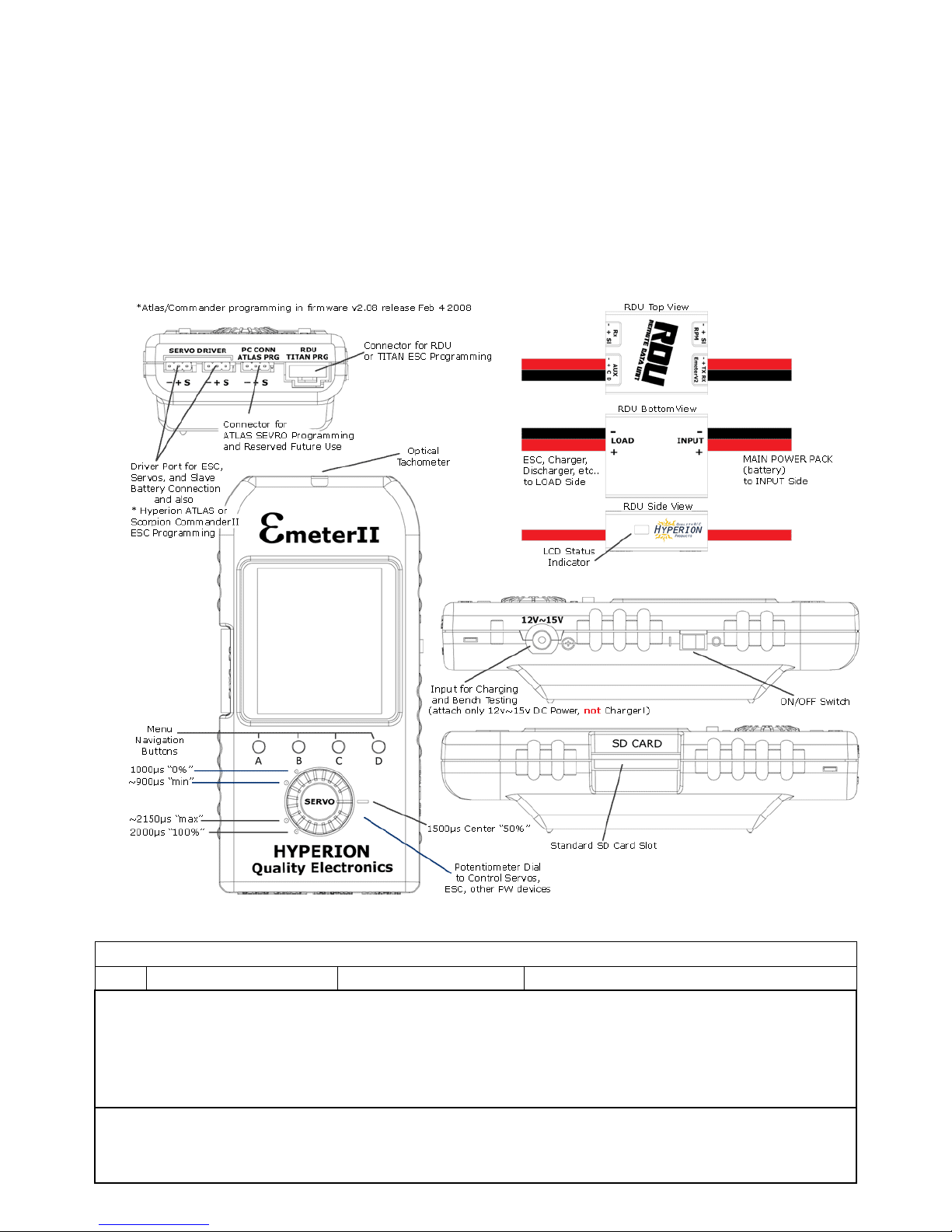
The Emeter II System consists of two major components:
• The pocket sized case houses the display screen, an SD Card slot, buttons for menu navigation, a
potentiometer to drive pulse-width devices such as servos and motor controllers, an optical tachometer,
and an internal battery pack with onboard charger.
• A Remote Data Unit which, with its small size can be fitted to the power system (RC model, robot,
scooter, etc…) to log data. At the end of the logging period, the captured data can be copied to the
Emeter II for display, without the need for a Personal Computer.
In addition, the Emeter v2 comes with two cables in the box:
-- A Data Cable (aka “RDU Cable”, #HP-EM2-4PINCBL). It has a locking Molex 4-pin connector on one side
which fits the Emeter v2 at bottom-right port. The other side has 5-pin female connector (with one pin
“blanked”). This side fits the RDU so that the RDU can transfer files to Emeter, and communicate during Bench
testing or RDU setup. The same side also fits Hyperion TITAN series ESC, for programming via Emeter.
-- A Power Cable (#HP-EM2-PWRCBL) with 4.5mm plug on one side, and tinned wires on the other. The
Emeter contains a 5-cell 750mAh NiMH battery inside, and an INTERNAL CHARGER. You should never connect
a battery charger to this power input. Instead, simply use any 12V~15V DC power supply with 120mA or
higher capacity (such as a 13.8V DC power supply, Automotive battery, or discarded 12V “Wall PS” from some
old toy, router, etc). Please take time now to fit appropriate connectors to this cable, and plug in your
Emeter to a 12-15V power source for charging. See details below for charge rate and time.
Terminology
RDU – The Remote Data Unit contains data storage, and sensors for measuring voltage, current, height
(altitude from start point), ambient temperature and other data. In addition the RDU has input/output
connectivity to a receiver or pulse-width driver such that throttle position can be recorded or remote on/off of
logging controlled. The RDU can record peak currents up to 150A with stock wiring (up to 300A, 5 sec,
modified), with a maximum of 70V input. There are also optional sensors available for up to three external
temperatures and phase tachometer for brushless motors at this time, with other sensors planned for 2009.
Before using the RDU, it is necessary to solder on the connectors of your choice to the RED/BLACK wires
marked INPUT (Battery, DC PS) and LOAD (Motor, Charger, Discharger, etc) on RDU bottom. The connectors
must be high-quality and matched in size to the maximum currents you expect to draw. Although the RDU is
protected against accidental connection with polarity reversed, the ESC which is normally connected to the
LOAD side of the RDU, is likely not protected and will be destroyed by reversed polarity. So take great care with
connector polarity.
ESC
- Electronic Speed Controller is used to vary the speed of the model’s motors
BEC
- Battery Eliminator Circuitry, optionally included in the ESC, is used to power receiver/servos from main
power pack instead of a separate receiver pack
SD Card
– is a mass data storage device which may also be used for transfer of data between a PC and the
Emeter II, including:
• Emeter II and RDU firmware updates
• Files for On-line screen help
• Prop constants data
• Data logs
• Parameters for user-programmable servo or ESC drivers
An SD card is not included but is strongly suggested for complete functionality. Standard (or Mini/Micro in adapter) SD SDHC
cards up to 4Gb are supported. They must be formatted as FAT16 or FAT32.
Phase Tachometer
sensor – (option part # HP-EM2-TACHBL) has a single wire which should be connected to
any of the three wires into a brushless motor, and the 3 pin plug which fits the RDU socket labelled ‘RPM’.
External Temp 1,2,3
sensors – (option parts #HP-EM2-TMP1 and #HP-EM2-TMP23) Note that Temp#1 must
be purchased in order to add temps #2 and #3, as only TEMP#1 connects direct to RDU (2,3 connect via #1).
Page 2
On Screen Help and Navigation
Features are accessed by selection from a multi-level menu. Button numbers are shown in quotes for example
‘A’, ‘B’, ‘C’ or ‘D’ and have an abbreviated description on the bottom row of the display. Button ‘A’ on the MAIN
menu will display Tips on RDU and Emeter II firmware version upgrades. Navigation through the menus is
achieved by pressing ‘D’ until the required menu item shows in larger characters. Once this occurs,
• press ‘B’ to display screen help relating to the selected function or
• press ‘C’ to go to the selected function.
There are two basic modes of operation – ‘Bench-Test’ mode in which the RDU and the Emeter II are connected
for use together, and ‘In-Action’ mode where the RDU is used alone. In Bench-Test mode, RDU is cabled to the
Emeter and data is recorded directly to the Emeter’s SD card, whereas In-Action mode stores the data in the
remote RDU from which it is later copied to the Emeter II SD card. After switching the Emeter II on, the
function which was in use at the previous switch off time will re-appear. In most cases, ‘A’ will cause a return to
the previous, higher menu item or screen. Certain actions may cause deletion of data which could be critical.
You will be warned if this is the case and requested to confirm the action.
OPERATION NOTES
EMETER BASIC SETUP
Function Screen/Mode Cables/Wiring
1.1 Internal battery Charging 12-15 volt supply with the supplied 4.5mm plug
The Emeter II will automatically charge while connected to 12-15V PS whether the unit is in use, or switched off.
The Emeter can be used while connected to 12-15V power source (i.e. during bench testing can be left connected)
Charging will occur at 85 ma and take 9 - 12 hours at this rate from a fully discharged state.
The battery will last between 18 and 50 hours, depending on use of screen backlight, connection to RDU and other factors.
Main menu shows internal battery charge state indicator. Reconnect to 12-15V PS before this falls to 0%. The date and time
will need to be reset if the internal battery is allowed to go flat.
1.2 Set Date/Time MAIN>EMETER SETUP
Press ‘D’ (next) to move to date or time lines.
Press ‘B’ or ‘C’ to decrease or increase the fields as required. Hold button down for accelerated change.
These fields are used to add a timestamp to log files or snapshots (see 4.1 – 4.3).
Page 3
EMETER BASIC SETUP continued
Function Screen/Mode
1.3 Screen Backlight MAIN>EMETER SETUP
Press ‘D’ to move to LCD Light line and pick
‘Off’ for no backlight
‘On’ for constant backlight
‘Auto’ for backlight on for 10 seconds duration whenever a button is pushed Default setting is ‘Auto’.
1.4 Contrast MAIN>EMETER SETUP
Press ‘D’ to move to Contrast and pick a number between 15 and 30 for desired effect.
1.5 Button Beeps MAIN>EMETER SETUP
Press ‘D’ to move to Beeps and pick ‘On’ or ‘Off’ for a ‘click’ or ‘beep’ each time a button is pressed . Default setting is ‘On’.
1.6 Height & Temperatures MAIN>EMETER SETUP
System holds figures in Metres and Celsius and will convert and display Feet and Fahrenheit if so specified here.
INSTANTANEOUS READINGS (and Tacho Setup)
Function Screen/Mode Cables/Wiring
2.1 Tacho - configure Optical Tach READINGS>TACHO>push ‘C’ > CONFIG TACHO None
Set Tacho Source as Emeter by pressing ‘B’ or ‘C’. Press ‘D’ and set blades as 1 to 6.
Without the RDU connected, the source will be set to Emeter automatically.
-- Set Tacho averaging:
On averages rpm over 2 secs if < 9,000 rpm. Averages rpm over 1 sec if > 9,000 rpm
Off averages over 1 sec always. Press ‘A’ to save tacho configuration
2.2
Tacho: configure Phase Sen.
Tach
READINGS>TACHO>push ‘C’ > CONFIG TACHO
*The RDU Tacho is for brushless motors and ESC only *
RDU + RDU cable +
Phase Tach
With the Emeter II, RDU and the phase sensor pick-up lead connected, the source can be selected as either
• Emeter II for the optical tacho or
• RDU for the phase sensor tacho
For RDU, the number of Motor Magnets must be set or erroneous results will occur. Set Gearbox ratio (“1” for direct drive)
2.3 Determine Motor Magnet Count READINGS>TACHO push ‘C’ > CONFIG TACHO
RDU + RDU cable +
Phase Tach
Run the motor at steady speed with Emeter II close to spinning prop.
Vary no. of magnets until the RDU and Emeter II Opto rpm figures match and Save configuration.
2.4
Tacho - Read RPM optical READINGS>TACHO None
Hold top of Emeter II about 10 cm from rotating prop. Wait until readings steady. Avoid fluorescent lights
Press ‘D’ to hold reading (see sect 4.1). Press ‘C’ to save reading to SNAPSHOT 1-8 (see section 4.3)
Press ‘B’ to set prop constants, if known and show motor output power (see section 5)
2.5
Tacho – Read phase sensor RPM READINGS>TACHO or
READINGS>ANALYSER
RDU + RDU cable
+ rpm sensor cable
Connect rpm sensor lead to RDU RPM socket and to any of the 3 wires of brushless motor. * Do not use on brushed motors *
2.6 Read Volts Bench-Test READINGS>ANALYSER RDU + RDU cable
0 to 70 volts, 2 dec. places
2.7 Read Amps Bench-Test READINGS>ANALYSER RDU + RDU cable
0 to 150 amps peak, 1 dec. place. BATTERY shows voltage, max. and min. and ma-h energy input and output (charge &
discharge)
2.8 Watts into ESC/Motor READINGS>ANALYSER RDU + RDU cable
0 - 10000 watts, calculated as the product of Volts * Amps
2.9 Motor/ESC Efficiency READINGS>ANALYSER RDU + RDU cable
Displays efficiency if Prop Constants in place and less than 100%. Press ‘D’ to hold values on screen. Press ‘C’ to save values
in SNAPSHOT 1–8
2.10 Motor Output Power & Thrust READINGS>TACHO None
Display power in Watts and BHP and thrust in grams if propeller constants exist for the given prop.
2.11 Height READINGS>ANALYSER RDU + RDU cable
The height sensor is fitted in the RDU and is set to zero metres when power is connected to the RDU. Position in model may
affect readings. See Emeter II manual for more.
Page 4

ACCUMULATED and PEAK DATA
Function Screen/Mode Cables/Wiring
3.1 Capacity mAh Input READINGS>BATTERY or READINGS>ANALYSER
Accumulates even when on other screens
RDU + RDU cable
From 0 – 65000 mA-h. Records charged capacity automatically, whenever current is flowing through the RDU. Press ‘C’ to clear
mA-h In when on BATTERY screen. NOTE: Capacity will continue to log in the RDU even if the Emeter II is switched off.
3.2 Capacity mAh Output READINGS>BATTERY or READINGS>ANALYSER
Accumulates even when on other screens
RDU + RDU cable
From 0~65000 mA-h. Records discharged capacity automatically, whenever current is flowing through the RDU. Press ‘C’ to clear
mA-h ‘Out’ when on BATTERY screen. Note: Capacity will continue to log in the RDU even if the Emeter II is switched off.
3.3 Max Volts READINGS>PEAKS RDU + RDU cable
Peak values recorded for whole session or from when ‘B’ (Clr) pressed. These values are lost when switching the Emeter II off
unless saved to SNAPSHOT 1 – 8
3.4 Min Volts READINGS>PEAKS RDU + RDU cable
As above. Useful to assist in protecting batteries from over-discharge.
3.5 Max Amps READINGS>PEAKS RDU + RDU cable
As above. Useful to assist in protecting batteries and ESC from over-current conditions.
3.6 Max RPM READINGS>PEAKS RDU + RDU cable
Peak values recorded for whole session or until ‘B’ (Clr) pressed.
3.7 Pack resistance Ohms READINGS>PEAKS RDU + RDU cable
Start discharge, press ‘B’ (Clr), stop discharge or Press ‘B’ (Clr), start and stop discharge. Resistance will be shown in ohms
SNAPSHOTS for short term saving of readings
4.1 Hold Display On TACHO, PEAKS, ANALYSER, BATTERY screens RDU + RDU cable
Press ‘D’ to hold – 2nd press continues, as if no hold took place
4.2 Save snapshot As for Hold RDU + RDU cable
Press ‘C’ to save in one of 8 SNAPSHOT locations for later recall, select SNAPSHOT 1 to 8 by pressing ‘D’, if required.
Press ‘C’ again to resume original activity. Data stored in first empty SNAPSHOT location by default. Snapshots are retained when
the Emeter II is turned off, but for long term data retention, see data logging facility
4.3 Snapshot Recall-Clear READINGS>SNAPSHOTS None
Shows up to 8 snapshots taken from ANALYSER, BATTERY, SNAPSHOTS or TACHO screens These are stored internally, not on the
SD card. Press ‘D’ to scroll through snapshot 1 to 8. Display is in format of screen from which the save was originally made.
For ANALYSER or TACHO data press ‘B’ to view or specify Prop. constants. If these exist, then the calculated efficiency and/or
propeller thrust in grams will show. Clear snapshot by pressing ‘C’
PROP CONSTANTS for calculation of motor efficiency and thrust
Function Screen/Mode Cables/Wiring
5.1 Prop Constant Background
Prop constants can be used to calculate motor/ESC power/efficiency and also thrust for given RPM. See PROP TALK tutorial in
Hyperion Website at www.hyperion.hk/dn/em2 . Emeter II can look up prop constants from a PROPS.TXT file held on the SD Card
or will accept constants entered manually onto the CONSTANTS screen. The latter are given the name ‘Other’. For either case, the
last-used propeller details are retained for subsequent power, efficiency and thrust calculations
5.2 Prop Constant Viewing READINGS>PROP CONST or
READINGS>ANALYSER> button ‘B’ (Prop) or
READINGS>TACHO> button ‘B’ (Prop)
SD Card
If SD Card contains PROPS.TXT file, browse props via buttons ‘B’ (Dec) and ‘C’ (Inc). To select required file press ‘A’ (Save)
5.3 Prop Constant Entry READINGS>PROP CONST or
READINGS>ANALYSER> button ‘B’ (Prop) or
READINGS>TACHO> button ‘B’ (Prop)
Press ‘D’ (next) to move to Power Constant field, use ‘D’ to move to figure to be entered and ‘B’ or ‘C’ to change to required value.
Use ‘D’ to move to next figure and repeat process in the same way. Once numbers are correct, press ‘A’ to save for all future
calculations until changed and saved again. Prop name will change to ‘Other’
5.4 Prop Constant Entry Notes
Motor output power, efficiency and thrust figures are not calculated for In-Action mode since propeller constants do not apply to
moving models. Only Bench-test mode can record power, efficiency and thrust. See manual for details.
Page 5

DATA LOGGING
Function Screen/Mode Cables/Wiring
6.1 Data Logging Bench-Test
mode
READINGS>ANALYSER or
READINGS > BATTERY
RDU + RDU cable + optional RPM or
temperature sensors
Press ‘C’ to log readings to SD card or to cease logging under full user control. Each start creates a new log file with unique file
number and showing date and time. Blinking message on screen acts as recording indicator.
Warning, do NOT power off the Emeter II while logging is in progress.
Press ‘C’ on BATTERY or ANALYSER screens to stop logging first.
6.2 Set RDU data logging
parameters for the InAction mode
MAIN MENU>RDU SETUP RDU + RDU cable
Set Trigger type for start of logging:
• Amps – start logging when actual current exceeds specified trigger amps
If amps fall below trigger level, then logging will stop if the RECORD SECS (expiry time) has elapsed.
• Increase amps above trigger current to resume logging. There will be multiple sets of data readings – one set for each time the
actual current rises above then falls below the specified trigger amps. These different sets will all be down-loaded to the SD
card as a single file. The time display resets to 0 at the start of each set. For continuous logging after amps start, set expiry
record time = 0 or very high. If the RDU is unplugged from the main power source, then, once the RDU and power source are
re-connected, a new data log file will be created. The download action, if chosen, will copy all files from the RDU to the SD card
• Time – this option is used for motor-less models which cannot use an AMPS based trigger. Logging begins once start delay
seconds have elapsed after RDU connected to main Power Pack and continues until the RDU is disconnected or the record time
expires
• Manual – logging controlled by signal from spare receiver channel. Pulse width < 1300 μs. will stop logging and > 1700 μs
starts logging
Set recording expiry time (in secs.) for data logging session or zero for unlimited length
Set sample rate from 4 per second to 8 secs. per sample. This sample rate applies to both In-Action and Bench-Test modes.
Save logging parameters by pressing ‘A’
6.3 Set up RDU logging of:
Amps, Volts, RPM, Ambient
temp, 3 external temps,
height
RDU + optional RPM and temperature sensors
NO RDU cable from RDU to Emeter II
3 wire cable from spare Rx channel to RDU
Rx input (for manual logging start)
- Connect optional rpm sensor to RDU RPM port and any one of brushless motor input leads. Note that the ambient temperature
and height will be recorded automatically by sensors built in to the RDU. Connect option temp. sensor #1 to the 4 pin plug on the
RDU marked ‘AUX’, and connect option Temps #2 and #3 to Temp #1. Where possible, use adhesive tape to prevent movement
between the sensors and target to ensure good contact (example, motor, power pack and ESC).
- Connect RDU main power wires to ESC. When ready to run model, connect RDU to power pack. Green LED should flash on RDU
at the sample rate. Green LED changes to red whilst logging is in progress. Time based logging will stop when the Record Secs. on
the RDU SET-UP have elapsed or the RDU is disconnected from the model’s power-pack.
Amps triggered logging will stop when the Record Secs have elapsed AND the current drops below the trigger amps.
Logging will resume again if the current rises above the trigger amps; a fresh Record Secs time will apply
6.4 Download
Data to Emeter II
At switch on-time an automatic message
appears if RDU carries data which has not
been downloaded
RDU + SD Card + RDU cable
Connect RDU to Emeter II via RDU cable
Switch Emeter II on – should receive message ‘found dataset – download now?’
Reply ‘Yes’ by pressing ‘D’ or ‘A’ to defer the transfer of data held in the RDU until later
The progressive status of download is shown and the data is downloaded to the SD Card with a unique file number and showing the
date and time of the download
6.5 View log files MAIN>LOG FILES SD Card
Use ‘D’ to browse to required log file. Log files have a unique file number and show the date and time stamps which are set to the
date and the time of:
• the download from RDU to Emeter II or
• the time when a Bench-Test log file was created
Logged data for both In-Action and Bench-Test consists of:
Time
Volts
Amps
Rpm
Watts Input
Height
Ma-h out
Ma-h In
Ambient Temp
Sensor 1 temp
Sensor 2 temp
Sensor 3 temp
6.6 Graphing of log files MAIN>LOG FILES SD Card
After highlighting a Log File from the list, press ‘C’ to select. The Graph function will allow any two of volts, amps, height and rpm
to be plotted against time. For full details, refer to Emeter II Manual.
Page 6

TIMERS & STOPWATCHES
General notes on Timers and Stopwatches - On entering any one of the three stopwatch screens, a check is made for any
previous timing data for this particular stopwatch mode. If this exists, then the stopwatch will display the previous data. If the
data was initially captured using a different stopwatch mode, then a warning is issued and the option to clear data is given. All
stopwatch and countdown functions will remain running while using other Emeter II screens.
Function Screen/Mode Cables/Wiring
7.1 Stopwatch/lap count mode MAIN>STOPWATCHES>LAP COUNT None
Use to time any competition for which individual lap times and counts are needed. Records up to 100 ‘events’ which may be lap
times or stopwatch starts/stops.
Start stopwatch with Button D - shows time as Primary (PRIM)
Press button C at end of each lap. Lap time and the lap number show on lower half of screen.
SPLT is the value of Primary time as of last button C press.
Press button D to pause both Primary and lap timers
.
Press ‘C’ to recall laps from beginning
7.2 Stopwatch- Dual Mode MAIN>STOPWATCHES>DUAL MODE None
Use for timing one activity within a second for example one individual lap within a multi-lap race
Use ‘C’ to start/stop the secondary stopwatch and ‘D’ for primary stopwatch
Secondary watch only runs whilst primary is running
All events such as watch starts and stops are included in the list and may be recalled later if the Emeter II is switched to another
function
7.3 Stopwatch-Auto Mode MAIN>STOPWATCHES>AUTO MODE None
Same as Dual Mode, except that a single push of ‘D’ will automatically start both watches
7.4 Count Down Timer MAIN>STOPWATCHES>COUNT DOWN None
Press ‘B’ (set) followed by ‘B’ or ‘C’ (increase or decrease) to change countdown start time. Hold these buttons down for
accelerated change.
Press ‘D’ to save – current time will be reset to countdown start time.
Press ‘D’ to start countdown and ‘D’ a second time to stop/pause if required.
When the countdown timer is running, pressing ‘A’ will allow use of most other Emeter II functions, such as Tacho or servo test
without interrupting the countdown.
At the end of the specified time:
A 3-second-long beep will sound even if the Emeter II is in use on a different screen/function
The current time will start increasing ‘TIME OVER’ will be displayed
SERVO and ESC PROGRAMMING
8.1 Titan ESC Programmer MAIN>PROGRAMMING>TITAN ESC Unplug Emeter II-RDU cable from RDU
Plug RDU cable into TITAN ESC 4-Pin
Connect 4 wire cable from Emeter II to TITAN ESC and press ‘D’ (connect).
Emeter II will display all settings which may be changed. If display fails to appear, check the polarity and fit of the plugs.
Press ‘D’ to move to required parameter and ‘B’ (Configure) to change the value.
Press ‘A’ to save new settings. (see full manual for programming details)
8.2 Hyperion ATLAS and
Scorpion Commander II
ESC Programmer
MAIN>PROGRAMMING>ATLAS ESC
(this feature added in v2.08 firmware)
Requires ESC Connector plugged to SERVO
DRIVER left Port
(Brown wire is Negative, Orange is Signal)
FIRST, note that the POT Driver Dial on Emeter, and its two servo driver ports, are almost always “active” no matter which Emeter
screen one is viewing at the moment. So BE CAREFUL whenever an ESC and motor are connected, to avoid unintentional starts!
Connection Sequence:
* TURN POT DIAL on Emeter to Minimum Position (fully counter clockwise, ~900uS)
* Press Button ‘B’ (Type) to select ESC voltage rating (rating is printed on ESC heat sinks)
* Connect ESC 3-pin to leftmost Servo Driver Port at rear of Emeter
* ONLY OPTO ESC (50v and 68v types): also connect a 4.8v~6.0v Rx battery pack to the other Servo Driver Port
* Connect Main Power Pack to ESC Red/Black Input Wires
* Press ‘D’ (Go)
Select the function you wish to change with button ‘D’ (Next) and use ‘C’ (Set) to scroll through options. When all settings are as
you wish, press ‘B’ (Save). Settings are made one-at-a-time, so it may take some time to finish. Press ‘A’ (Exit) to leave without
making changes. See Full Manual for details.
8.3 Atlas Digital Servo
Programming
MAIN>PROGRAMMING>ATLAS SERVO
Plug in digital servo as per on-screen diagram. Press ‘D’ and, by using ‘B’ or ‘C’, make changes to:
• Direction
• Deflection
• Speed
• Centre
• Deadband width
Save changes with ‘A’
See Full Manual for more details
Page 7

MANUAL & AUTOMATED TESTING (for Servos, Motor/ESC, and other pulse-width-driven devices)
Note: In v2.08 Main Menu Item “SERVO TESTER” has been renamed “TESTING”. TESTING now leads to a sub-menu, with SERVO
TESTER (same as previous) and RUN PROFILE options. RUN PROFILE has been completely redesigned and greatly enhanced. See
below, and Full Manual for more details. While on TESTING at Main Menu, you may press ‘B’ (Help) for tips on both functions…
Function Screen/Mode Cables/Wiring
8.4 Servo Cycle Testing –
simple start/end
MAIN>TESTING>SERVO TESTER Servo and Rx battery
Plug in servo and receiver battery as per on-screen diagram. Note, servo and battery sockets are interchangeable.
From EM firmware release 2.06 onwards, there are two alternative techniques for specifying a test run:
• Simple start/end points chosen, with servo cycling between these two limits
• User defined profile: created on a PC and loaded onto the SD Card, or create directly on the Emeter II. (see next section)
Simple start/end point. As instructed on the screen, move the potentiometer (pot) to the start position (0%) and press ‘D’
(next). Move POT DIAL to end position (100%) and press ‘D’ (Start). SEE DIAGRAM PG. 2
Both the start and end positions will display the pulse width which will be in the approximate range 1000 – 2000 microseconds
The servo will cycle between the two end points.
Press ‘C’ to stop cycle testing
8.5 Servo Testing by Profile MAIN>TESTING>RUN PROFILE Servo and 4.8~6.0V Rx battery
Creation of a test profile. A test profile routine consists of a series of records, each containing a signal pulse width in
microseconds and a delay time in milliseconds. This tells the servo how far to move and how long it should stay there. The profile
itself can be created on a Personal Computer as a simple text file with 8-character-max name, but must have a .dat extension
and must sit in the data directory on the Emeter’s SD card. The header record is followed by any number of position/time records:
PW-uS,DELAY-mS (These notes in parentheses should NOT appear in the Test Profile File!)
01500,01000 (Atlas Servo Center, 1 second)
01000,00500 (Atlas Servo Full Right, 0.5 second)
02000,00500 (Atlas Servo Full Left, 0.5 second)
‘SERVTEST.dat’ above is included as a sample in the v2.08 upgrade file package, DATA folder.
See Full manual for full details on creating profiles via PC text editor or directly on Emeter.
Use of existing profile. At the RUN PROFILE screen press ‘D’ (Next) to select a profile from the list. Press ‘‘C’ (go), which then
takes you to the PROFILE TEST screen, where various automation options can be chosen.
The eight parameters below can be set by pressing ‘C’ (Cfg) button, then ‘D’ (Next) to select a parameter, and INC/DEC buttons to
set the values for that parameter. When all parameters are set as you like, press ‘A’ (Save)
REPEAT determines whether the test profile is to be executed Continuously or Once Only
LOGGING (Yes/No): Turns logging ON of OFF during the test run, as desired.
THE FOLLOWING PARAMETERS WILL AUTO-TERMINATE THE TEST according to your settings and the corresponding data streaming
into the Emeter from RDU. They therefore require that the RDU be connected to the Emeter, and that the RDU is powered via its
INPUT leads (usually the main power pack in a motor test system). If RDU is NOT connected, these settings are ignored.
VOLTAGE (min): 1V~70V in 0.2V steps
CURRENT (max): 1A~200A in 1A steps
TMP1, 2, 3 (max): 1~120 degrees Celsius in 1 deg. Steps (note that TMP only require RDU connection to Emeter, not MPP)
mAh-OUT (max): 10mAh~65000mAh in 10mAh steps
Each of the settings above has default setting of OFF, meaning that they will not affect testing in that case.
See Full Manual for more information on using Profiles and the auto-terminate settings above.
Deletion of unwanted profile: From PROFILE TEST screen, press ‘B’ to delete the current profile and ‘D’ to confirm deletion.
You will then be returned to the RUN PROFILE screen, where you may select, or create, a different routine.
8.6 Auto Power System Test
MAIN>TESTING>RUN PROFILE>PROFILETEST
Servo and Rx battery
This is identical to the above automated servo testing from a profile, except that the ESC replaces the servo, and the AUTOTERMINATE settings listed above become VERY useful… As such, users will have the option of stopping tests automatically if any of
TMP1, 2, 3, mAh-OUT, or CURRENT exceed max selected value, or if VOLTAGE falls below the minimum you have set. Very handy
for automating testing, and insuring that no equipment is over-stressed!!
For Power System testing, we assume that you will want the LOGGING option set to YES. Press ‘D’ (Strt) to start the automated
test. When ‘D’ (Stop) button is pressed, the system will return to the first line in the Profile File and output whatever pulse-width is
specified in the profile. If logging is ON, the Log will also stop when ‘D’ (Stop) is pressed.
We strongly recommend that any test profile which is to be used for driving an ESC and a motor should have the first
few seconds in the profile set to a motor-off signal such as 900 uS. If, during a profile controlled ESC motor test, there is an
urgent need to terminate the run quickly, then it is only necessary to press ‘D’ Stop if first line is 900uS.
See Full Manual for more detail and tips, and a sample Motor Test Routine (MOTRTEST.dat included in v2.08 upgrade file package)
8.7 Manual Servo/ESC Driving From any screen at any time ESC (opto esc require 4.8-6.0V Rx battery)
Connect Emeter II, Rx battery and servo or ESC as for Servo Cycle Testing, but exit from the cycle testing screen.
Rx battery MUST BE LEFT OUT if the ESC has BEC circuitry, UNLESS the +V wire to the ESC is disconnected
Set the Emeter POT DIAL to the throttle closed position - fully anticlockwise.
For model aircraft, initially test for correct wiring and functioning with no propeller, as a safety precaution.
Turn POT to drive the Servo or ESC.
Page 8

FIRMWARE UPGRADE and CALIBRATION
Function Screen/Mode Cables/Wiring
9.1 Calibrate volts MAIN>RDU SETUP
Hold ‘D’ for 3 secs. to allow access to
Upgrade and Calibrate functions
RDU + RDU cable
Plug RDU into power source with known voltage. Increment/decrement to match voltage. Save twice
9.2 Calibrate Current (amps)
Plug RDU into power source. Discharge at known current. Increment/decrement to match amps. Save twice.
9.3 Upgrade Emeter II
Firmware version
Before switch-on, press Buttons ‘A’, ‘B’, ‘C’
and ‘D’ while switching power to Emeter II
SD card
Firmware loader process checks for file EMFW.bin on SD card and, if found, loads the new firmware version into the Emeter II.
9.4 Upgrade RDU
Firmware version
MAIN>RDU SETUP
Hold ‘D’ for 3 secs. to allow access to RDU
Upgrade function
SD card + RDU + RDU Cable
Firmware loader process checks for file RDUFW.bin on SD card and, if found, asks the user for confirmation before upgrade.
NOTE: v2.09 firmware contains identical features to v2.08, but fixes several bugs:
1) Intermittent FAIL to save RDU configuration settings
2) Peak RPM not accurate if user enters RDU setup while motor test in progress
3) If atmospheric pressure abnormally low at RDU power ON time, HEIGHT data corrupted
Page 9

RDU SPECIFICATIONS (for RDU Type #HP-EM2-RDU)
Max Input Voltage 70V
Max Current 5 seconds* 300 A
Max Current 30 seconds* 150 A
Max Continuous Current* 75 A
Shunt Resistance 0.0002 Ω
Internal Resolution V 0.001 V
Displayed Resolution V 0.01 V
Internal Resolution A 0.04 A
Displayed Resolution A 0.1 A
TMP Sensor Resolution 0.1 Celsius
TMP Sensor Accuracy 1%
Analog<>Digital Converters 16 bit
Phase RPM Max Readable 65,000 rpm
Phase RPM Resolution 17 rpm (14 mag.
motor)
EM2-RDU Sample Rate vs. Storage Time
Sample Rate StorageTime hh:mm:ss
4 samples/sec 00: 20: 50
2 samples/sec 00: 41: 40
1 samples/sec 01: 23: 20
2 seconds/sample 02: 46: 40
4 seconds/sample 05: 33: 20
8 seconds/sample 11: 06: 40
On connection to Emeter II, RDU will upload
saved logs to Emeter and clear RDU memory
2 samples/sec is default setting
*Note that the max currents listed above are highly dependant on ambient air temperature, and especially the amount of
cooling airflow that passes through the RDU. On a cold day with good airflow, you may increase Continuous and 30-sec Max
amperages by some percentage, or reduce for hot days and poor airflow. Currents above 150A require user modification to
increase input/output wire size, and appropriate connectors. The “bottom line” is that it is your responsibility to check
temperatures to insure the RDU is not heat damaged (75C max). RDU unit returned with clear evidence of over-current heat
damage will NOT be covered by warranty replacement policy.
Temperature
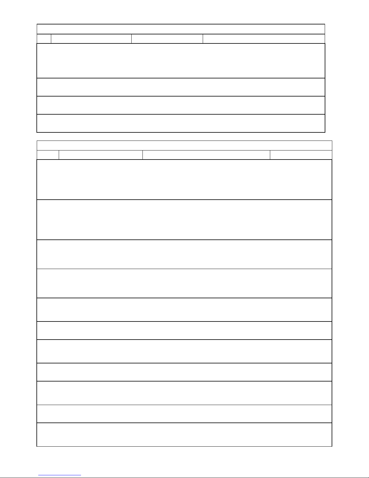
sensors
Phase Tacho
Connection
Emeter II
Brushless
Motor
Main
Power Pack
RDU
Remote
Data
Unit
BEC
Electronic
Speed
Control
Simple Diagram for the
Bench-Test of BEC ESC
and a Brushless Motor
4 wire RDU to
Emeter Data
cable
B
C
A
Connect to
Emeter Servo
Driver Port
To BEC ESC
Also see http://media.hyperion.hk/dn/em2 (bottom of page) for the “Emeter II Suite” PC Software, which allows direct
programming of RDU parameters, log file downloads from SD Card or direct from the RDU, and “live” bench testing with RDU
connected to PC. The Suite also contains graphing functions, and will soon support other features such as test profile
creation for upload to the Emeter.
WARRANTY
- Emeter and RDU are guaranteed to be free from defects in materials and workmanship for a period of one calendar year
from date of purchase.
- Damage due physical shock (dropping on the floor, etc), inappropriate power supply (battery charger, etc!), water,
moisture, over-voltage or over-current operation, and humidity are specifically NOT covered by warranty.
- Your selling dealer is your first point of contact for warranty issues.
- Return postage costs are the responsibility of the user in all cases. Submit copy of original receipt with the return.
- Returned units should be examined by the Hyperion dealer’s tech department within 1 week of arrival, maximum, and
contact made with the user to explain the findings.
REPAIR/REPLACEMENT DUE TO NON-WARRANTY ISSUES:
Due to the nature of the miniature electronics employed, and high cost of hand labor and shipping involved, it is not
economically feasible to repair electronics in many cases. Instead, we offer a blanket exchange policy at 55% of the US$
original suggested retail price (plus any taxes due in your area, and return shipping). In the event that your Emeter/RDU is
user damaged and warranty will not apply, please contact your selling dealer to obtain the correct return shipping address,
for exchange under this program.
Best regards from the Hyperion Team, tech@hyperion.hk
 Loading...