

Page 1
Indirect solar water heaters
100, 150, 200, 250 & 300 L Models
Installation, operation & maintenance manual
Solar Keymark
Certied
Page 2

2
SWH/HYPC/ENER
In the present manual you will nd all necessary instructions with regard to the installation, operation and maintenance of the product
GENERAL INFORMATION
Xilinakis & Co. have been manufacturing & supplying homes with quality solar water heating systems since 1975. The company’s
hightech, ultra-modern production facilities produce both their own Nobel brand of reputable turnkey solutions as well as providing
critical OEM components for numerous prominent thermal energy trademarks worldwide.
With many of their original systems still in operation, the advantages of a well maintained Nobel solar water heater has been habitually
validated to thousands of households for over 40 years, this experience & know-how has been diligently incorporated into the technically
pioneering new generation of Nobel Solar water heaters. Nobel combine the internationally renowned Aelios tank with their innovative
Apollon panels to create the “HYPERION” range of solar water heating systems. This combination creates a highly effective &
environmentally friendly energy solution that impeccably combines efciency with aesthetics, whilst achieving household autonomy with
astute monetary benets.
Easy to install & maintain, Nobel solar water heaters are constructed with top class materials under stringent quality controls, earning
Nobel & Xilinakis & Co. international certications in 26 countries on ve different continents. By producing hot water almost all year
round, Nobel solar water heaters can easily achieve between 80% - 100% reduction in conventional energy usage & are conveniently
compatible with either electrical resistance, gas or heat pump technologies for auxiliary power backup, ensuring that you will always
have hot water.
DOMESTIC HOT WATER CONSUMPTION
Maximising the benets of solar water heating is undeniably reliant upon the sizing of the system, this paramount point is in turn reliant
upon the household’s daily demand. The fact of the matter is that consumption levels in different households can easily vary from around
35, to well over 75 plus litres per person per day. It is imperative, therefore, that you choose the appropriate tank volume to suit the
daily requirements your lifestyle demands. Water draw off times & distribution parameters should be taken into account especially when
incorporating a ring main distribution system. To maximize the systems’ efciency; intense hot water draw off should be restricted to
before mid-day to allow the system time to recover enough energy to provide for the next evening/morning consumption. Over - sizing
the boiler slightly will add to the overall residual heat of the system & thus reduce reliance upon any auxiliary power backups. Ideally
one wants to heat up enough volume of water in six (6) hours (From 9 am onwards) to accommodate your consumption over the next
eighteen (18) hours & repeat, ad innitum.
General information ..................................................................2
Domestic hot water consumption .............................................2
Solar water heater operation ....................................................3
Packaging .................................................................................3
Labelling ...................................................................................4
Water storage tank specications .............................................4
Collector specications .............................................................5
Hyperion 100lt/1.5m
2
layout ......................................................6
Hyperion 150lt/2m
2
layout .........................................................6
Hyperion 200lt/2.6m
2
layout ......................................................7
Hyperion 250lt/4m
2
layout .........................................................7
Hyperion 300lt/4m
2
layout .........................................................8
General installation rules ..........................................................8
General safety measures .........................................................10
Lightning protection ..................................................................10
Support base parts ...................................................................10
Assembly on a at surface .......................................................13
Assembly on an inclined surface - OPTION A ..........................15
Assembly on an inclined surface - OPTION B ..........................16
Electrical connection .................................................................19
Hydraulic connection ................................................................20
Closed loop lling .....................................................................20
System with water storage tank under the roof
(Natural circulation operation) ..................................................21
System with water storage tank under the roof
(Forced circulation operation) ...................................................21
Post installation instructions .....................................................22
Service - maintenance ..............................................................22
Troubleshooting ........................................................................23
Post installation checklist ..........................................................24
Nobel / Enerjetic certicate of guarantee ..................................25
Installation information & system service record ......................27
Page 3
3
SWH/HYPC/ENER
SOLAR WATER HEATERS
SOLAR WATER HEATER OPERATION
The operation of the system requires UV irradiation from the Sun to heat up an aluminum plate inside the solar panel called an absorber.
The absorber, in turn, transfers this heat by contact to a liquid inside copper tubes that are ultrasonically welded to this aluminum
absorber. The tubes in the solar panel are connected via pipes to a steel jacket that completely encompasses the potable water boiler.
The heating of the liquid in the tubes creates expansion that makes the heated liquid lighter thereby causing it to “rise” to the top of
the jacket (this is why the boiler is positioned above the solar panels). This hot liquid will heat the jacket which, being in direct contact
with the boiler, will in turn heat the potable water inside the boiler. Cooler, heavier liquid from the bottom of the jacket that has already
dissipated its energy into the boiler, “sinks” down into the bottom of the panels, replacing the hot expanded liquid leaving the top & is
re-heated by the absorber & thus recycled through the system. This “ow” of liquid is created solely by heat transfer & the action of the
ow itself is called natural thermosyphon. The method of heating described above is what is termed of as an “indirect” solar system.
Instead of heating the potable water directly inside the panels, it employs a liquid anti-freeze solution in the panel tubing & jacket/heat
exchanger to transfer energy. This protects the system from freezing in frost prone areas. Importantly, the anti-freeze also has chemical
anti-corrosive properties protecting the copper tubing against calcite build-ups that would normally be left by potable water in extreme
operating temperatures. This design along with its robust construction make the Nobel solar systems extremely versatile & durable in
being suitable for practically any environmental conditions with adequate solar irradiation. To manage a solar water heater effectively,
one has to be cognizant of seasonal variations of directional solar irradiation & ambient temperatures; a typical solar system heating
water from an ambient 20 degrees to 55/60 degrees in three (3) hours at the height of summer, would take around six (6) hours to reach
similar temperatures in the mid-winter months with considerably lower solar irradiation & much colder ambient water temperatures to
deal with. It’s best to refrain from hot water consumption during peak heating times throughout the winter months. This allows the system
to store the maximum sum of energy out of the limited daily amount available.
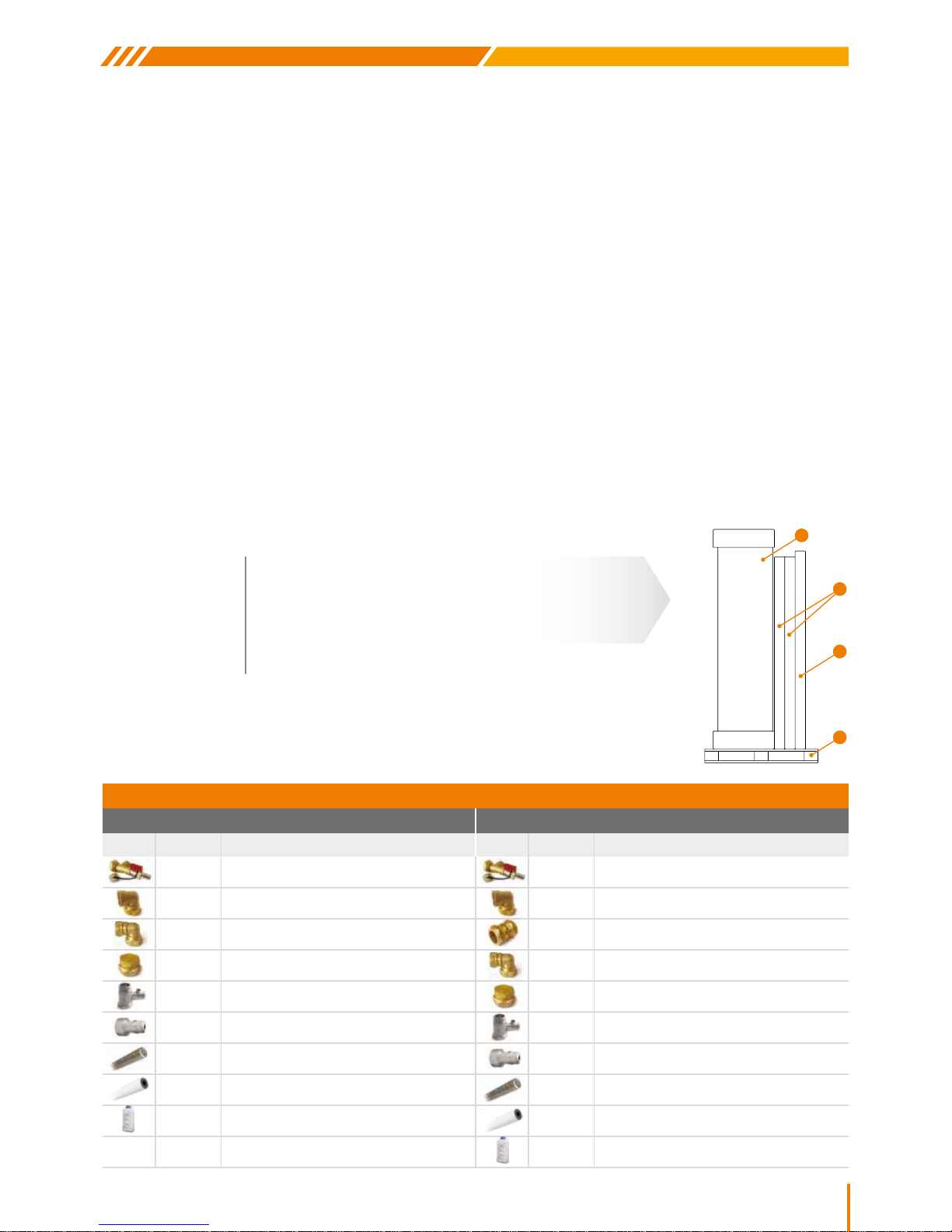
PACKAGING
The water storage tank is placed between two round styrofoam covers, secured onto the storage tank
with stretch lm. The collector is packed in a carton box. All the parts of the support base system,
with the connection ttings, the antifreeze liquid and the other accessories are packed in a carton box.
The ttings and the accessories of each appliance appear in the following table:
MODEL
HYPERION 100/1.5
HYPERION 150/2
HYPERION 200/2.6
HYPERION 250/4
HYPERION 300/4
DESCRIPTION
100lt tank, 1.5m
2
collector
150lt tank, 2.0m
2
collector
200lt tank, 2.6m
2
collector
250lt tank, 2 x 2.0m
2
collectors
300lt tank, 2 x 2.0m
2
collectors
1. Boiler
2. Collector(s)
3. Support base, ttings
& Accessories
4. Palette
1
3
4
2
SOLAR WATER HEATERS FITTINGS & ACCESSORIES
1 COLLECTOR 2 COLLECTORS
Quantity Description Quantity Description
1 PC T-PIECE WITH THE FILLING VALVE 1 PC T-PIECE WITH THE FILLING VALVE
1 PC ELBOW ¾’’ FEMALE DN16 INOX 1 PC ELBOW ¾’’ FEMALE DN16 INOX
2 PCS ELBOW Ø22 COPPER X DN16 INOX 2 PCS CONNECTOR Ø22 COPPER X Ø22 COPPER
2 PCS END CAP Ø22 COPPER 2 PCS ELBOW Ø22 COPPER X DN16 INOX
1 PC ONE WAY SAFETY VALVE 10 bar 2 PCS END CAP Ø22 COPPER
1 PC SAFETY VALVE 3.5 bar 1 PC ONE WAY SAFETY VALVE 10 bar
2 PCS INOX TUBE DN16 1 PC SAFETY VALVE 3.5 bar
1 PC INSULATION Ø22 X 9 2 PCS INOX TUBE DN16
* ANTI-FREEZE LIQUID 1lt 1 PC INSULATION Ø22 X 9
* ANTI-FREEZE LIQUID 1lt
* The volume of liquid depends on the conguration boiler / collector
Page 4
4
SWH/HYPC/ENER
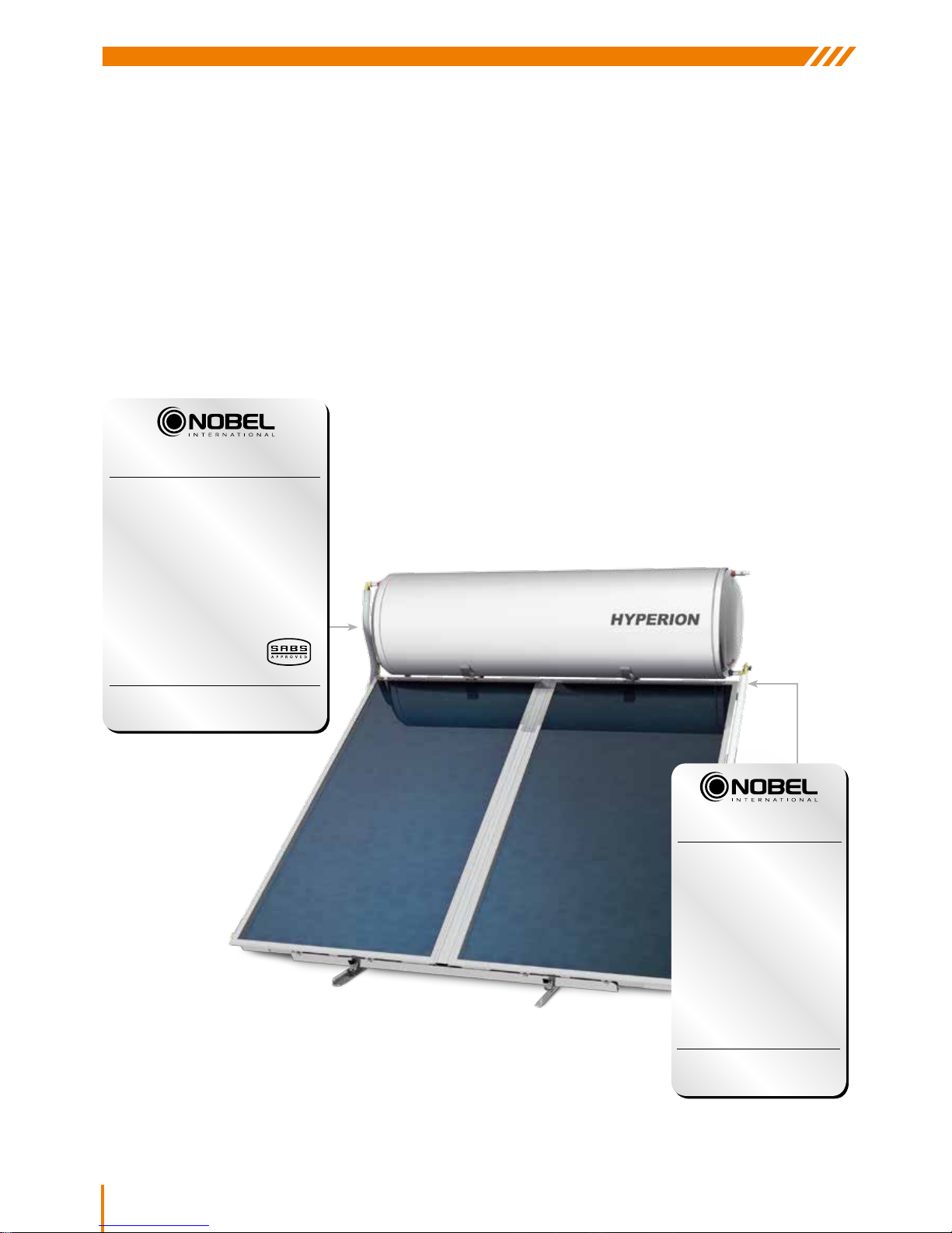
LABELING
HYPERION solar water heaters are clearly identied by two labels, one on the tank
and the other on the collector/s. These labels display all pertinent details relating to
the size, conguration & pressure ratings of the system. The information provided on
the stickers are also important for the future identication of the system.
*Systems distributed in South Africa include the following SA manufactured, SABS certied, Statutory SANS components:
1. Temperature / Pressure safety valve (Apex)
2. Vacuum breakers (Apex)
3. Drain cock (Cobra)
4. Electrical element (Satchwell)
5. Thermostat (Satchwell)
6. Thermostatic tempering valve (available from supplier on request only)
NOBEL INTERNATIONAL EAD
SOLAR WATER HE ATING SYSTEMS INDUST RY
48 Vitosha B lvd., 2100 Elin Pelin 2100, Bul garia
Tel.: +359 2 4210232 email: i nfo1@nobel.gr
Working Pressure: XXX KpA
Model Number: Apollon AL XXXX
Aperture Area: XXX m
2
Hail Cover: No
Hail Resistant: Yes
Freezing Test: Yes
Rated Capacity: XXX lt
Collector Type: Tempered low iron glass
Material of fluid
channel: Copper
Transfer fluid: 1 part Glycol
to 5 parts Water
(Consult the manual for exact mixtures)
Energy rating: XXX kWh
Date: ??????
S/N: ????????
MADE IN EU
Distribuited by Enerjetic Distributors
718 James Crescent Halfway House Midrand
Tel.: 0861 276527 - Fax: 0862 454781
email: info@enerjetic.co.za
ISO 9001:2008
NOBEL INTERNATIONAL EAD
SOLAR WATER HE ATING SYSTEMS INDUST RY
48 Vitosha B lvd., 2100 Elin Pelin, Bulg aria
Tel.: +359 2 4210232 email: i nfo1@nobel.gr
Working Pressure: XXX KpA
Manufacturer: Nobel
Model Number: Aelios XXXlt Indirect
Aperture Area: XXX m
2
Hail Cover: No
Hail Resistant: Yes
Freezing Test: Yes
Rated Capacity: XXX lt
Type: Closed
Design: Solar
Installation type: Roof/Floor - Horizontal mounting
Standing loss: XXX kWh
Power rating: XXX kW
Volts 230~50 Hz IPX4
Transfer fluid: Polypropylene Glycol / Water Mixture
Date: ??????
S/N: ????????
MADE IN EU
Distribuited by Enerjetic Distributors
718 James Crescent Halfway House Midrand
Tel.: 0861 276527 - Fax: 0862 454781
email: info@enerjetic.co.za
ISO 9001:2008
Page 5
5
SWH/HYPC/ENER
SOLAR WATER HEATERS
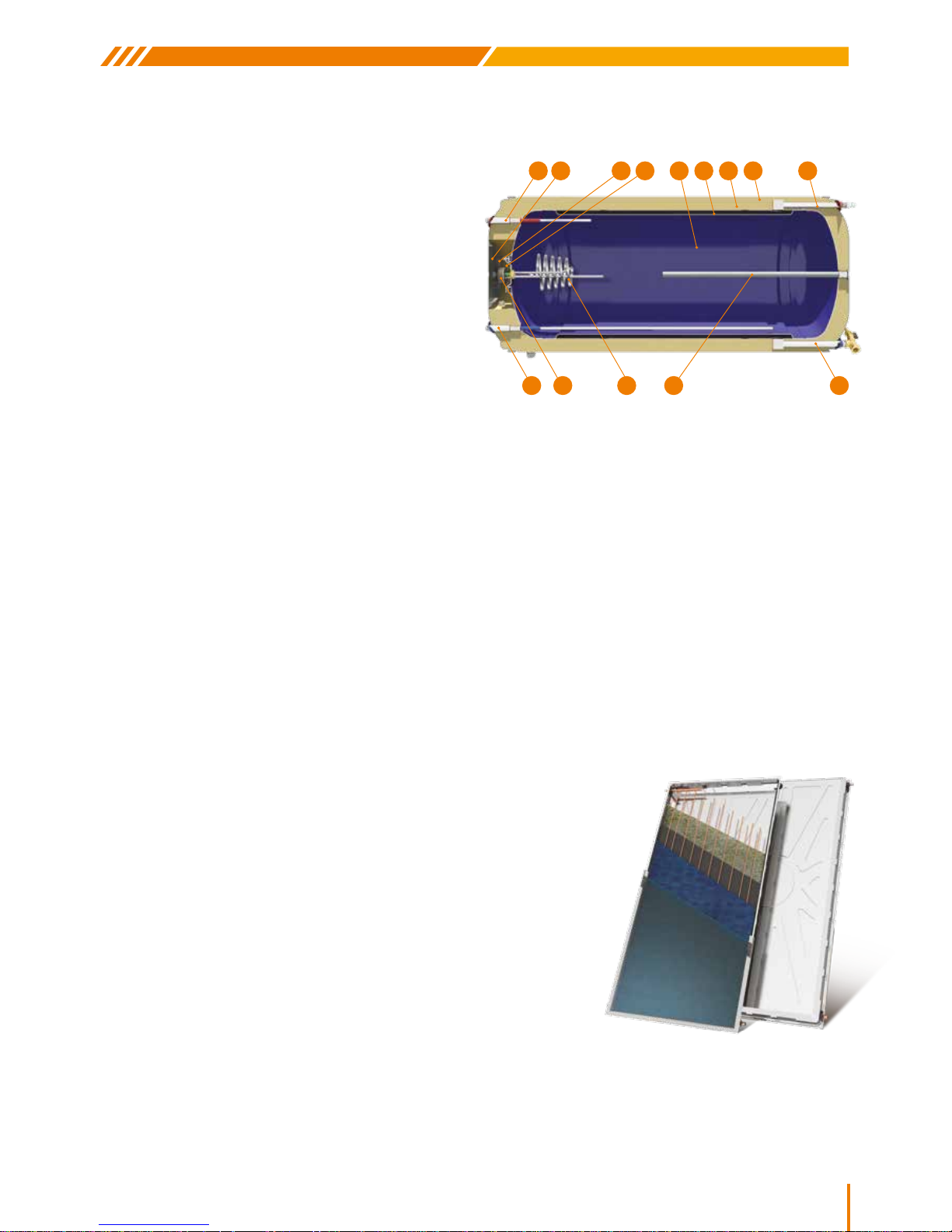
WATER STORAGE TANK SPECIFICATIONS
COLLECTOR SPECIFICATIONS
1. Cylinder: 2.5mm thick cold rolled steel with a double
internal layer of enamel, baked at 860°C according to DIN
4753. The enamelling is done in our own high tech industrial
facilities. Individually pressure tested at 15 bar. Nominal
working pressure: 10 bar
2. Surrounding heat exchanger (Jacket): for the operation
of the closed loop. Cold rolled steel, 1.5mm thickness
(compulsory for low temperature and water with high mineral
content). Pressure tested to 10 bar
3. Thermal insulation: ecological, high-density, expanded
polyurethane ensures minimum heat loss, maintaining the
hot water temperature
4. External housing: pre-painted galvanized steel with UV
protected, weatherproof end-caps
5. Cathode protection by magnesium anodes for effective
protection against corrosion and mineral deposits caused
by electrolytic reactions
6. Large round steel ange, rubber protected: innovative,
smart design for the quick cleaning of minerals and
immediate access to the electrical components. Universal
three pronged “pin” type element & thermostat seating
7. Complete sealing of non-toxic, EPDM material preventing
water coming into contact with the ange & thus protecting.
against electrolysis and corrosion
8. Heating element rated according to the country of
destination with respect to local regulations (for the use of
electricity as an auxiliary power source)
9. Automatically regulated thermostat with bipolar protection
and auxiliary fuse. All electrical components must comply
with local standards & markings
10. Protective cover: designed to ensure the proper ventilation
of the electrical section & protection from weather
11. Cold water inlet: INOX 3/4” BSPT male threaded pipe end
for water stratication and 10 bar safety valve for releasing
pressure
12. Hot water outlet: INOX 3/4” BSPT female threaded pipe end
13. Jacket inlet: 3/4” BSPT male threaded pipe end
14. Jacket outlet: Closed loop circuit lling point: 3/4” BSPT
male threaded pipe end
15. 3.5 bar safety valve connection location: 1/2” BSPT male
threaded pipe end
1012 15
176 2 3 4
11
14
8 59
1. External one piece aluminum trough of high aesthetics, shaped by deep drawing
method in a 400 ton press, made of naval aluminum alloy, rich in magnesium &
robust in construction for perfect tightness
2. High density, eco-friendly thermal insulation: 60mm thick layer of prepressed
rockwool with a covering of black glass fabric blanket for the minimization of
thermal losses
3. Water frame of copper pipes (headers: Ø22, manifolds: Ø8): Headers are
punched with upper expansion, for perfect manifold tting & thus avoiding
pressure drops in the collectors
4. Selective complete area absorber made of selective aluminum sheet with a
special titan coating, high absorbency and low irradiation. Laser welded to the
water frame
5. Special parts for supporting and sealing the water frame to the trough are specically designed for the collector’s ventilation
& has a sensor supporting option. Flexible silicone rubber seals allow for the uctuation of the absorber’s length (contraction expansion) from a -40°C to +200°C temperature range
6. Tempered solar glass low iron, with UV proofed rubber seal. Very stable coefcient of expansion, low reective, high light
transmittance & withstands most adverse weather conditions (e.g. hail storm, extreme temperature changes, etc.) trimmed with an
aluminium prole for solar glass seating, sealing and supporting
Page 6
6
SWH/HYPC/ENER
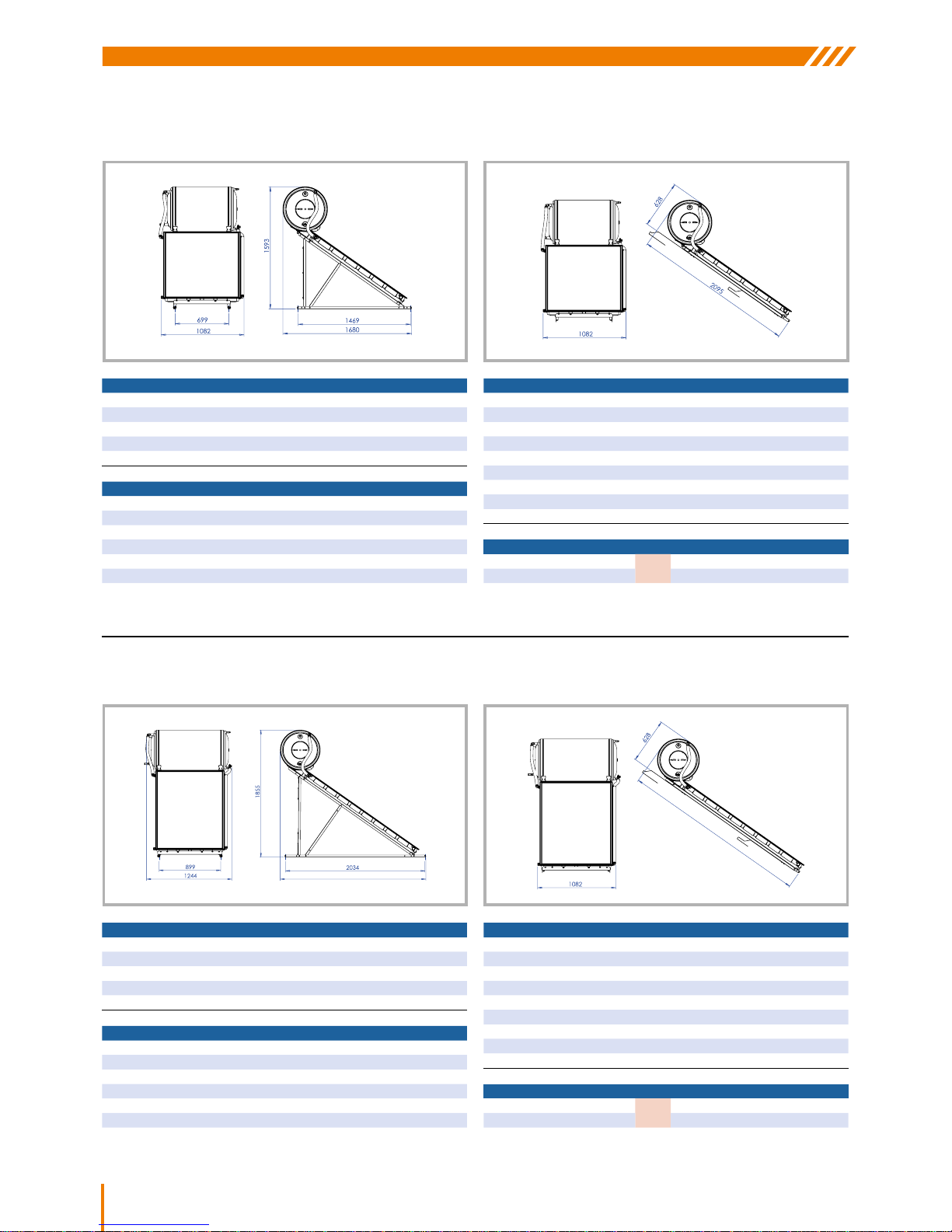
HYPERION 100lt/1.5m2 LAYOUΤ
Note: All dimensions measured in mm
COLLECTOR APOLLON AL 1500
TOTAL AREA (m²) 1.53
NUMBER OF MANIFOLDS 10
HEAT TRANSFER MEDIUM PROPYLENE GLYCOL SOLUTION
CAPACITY (lt) 1.45
ABSORBER SURFACE (m
2
) 1.34
TOTAL DIMENSIONS (mm)
1510x1010x110
COLLECTOR TOTAL WEIGHT (without liquid) (kg)
24.6
ABSORBER SELECTIVE ALUMINIUM
ABSORBENCY / RADIATION COEFFICIENT 95% ±2% / 5% ±2%
TOTAL SYSTEM HYPERION 100lt/1.5m
2
NUMBER OF COLLECTORS 1
SYSTEM WEIGHT EMPTY (packed) / FULL (kg) 98/214
MAX. WATER TANK OPERATING PRESSURE (bar) 10
CLOSED CIRCUIT MAX. OPERATING PRESSURE (bar) 3.5
MAX OPERATING TEMPERATURE 95°C
WATER STORAGE TANK 100lt
DIMENSIONS (mm) 580X906
WEIGHT EMPTY (kg) (without packaging) 52.2
JACKET CAPACITY (lt) 8.6
JACKET SURFACE (m
2
) 0.62
MAX TEST PRESSURE (bar) 15
MAX OPERATING PRESSURE (bar) 10
HYPERION 100/1.5m2 - JACKET AND COLLECTOR CAPACITY: 10lt
ANTIFREEZE LIQUID (lt) 1 2 3 4 5 6 7
MIN. TEMPERATURE (
°
C) -3 -5 -8 -11 -15 -20 -28
FLAT SURFACE INCLINED SURFACE
Note: All dimensions measured in mm
COLLECTOR APOLLON AL 2000
TOTAL AREA (m²) 2.03
NUMBER OF MANIFOLDS 10
HEAT TRANSFER MEDIUM PROPYLENE GLYCOL SOLUTION
CAPACITY (lt) 1.75
ABSORBER SURFACE (m
2
) 1.81
TOTAL DIMENSIONS (mm) 2010x1010x110
COLLECTOR TOTAL WEIGHT (without liquid) (kg) 38
ABSORBER SELECTIVE ALUMINIUM
ABSORBENCY / RADIATION COEFFICIENT 95% ±2% / 5% ±2%
TOTAL SYSTEM HYPERION 150lt/2m
2
NUMBER OF COLLECTORS 1
SYSTEM WEIGHT EMPTY (packed) / FULL (kg) 131.5/287.5
MAX. WATER TANK OPERATING PRESSURE (bar) 10
CLOSED CIRCUIT MAX. OPERATING PRESSURE (bar) 3.5
MAX OPERATING TEMPERATURE 95°C
HYPERION 150lt/2.0m2 LAYOUΤ
WATER STORAGE TANK 150lt
DIMENSIONS (mm) 580x1125
WEIGHT EMPTY (kg) (without packaging) 67.6
JACKET CAPACITY (lt) 14
JACKET SURFACE (m
2
) 0.98
MAX TEST PRESSURE (bar) 15
MAX OPERATING PRESSURE (bar) 10
HYPERION 150lt/2m2 - JACKET AND COLLECTOR CAPACITY: 15lt
ANTIFREEZE LIQUID (lt) 1 2 3 4 5 6 7
MIN. TEMPERATURE (
°
C) -3 -5 -8 -11 -15 -20 -28
2126
2551
FLAT SURFACE INCLINED SURFACE
Page 7
7
SWH/HYPC/ENER
SOLAR WATER HEATERS
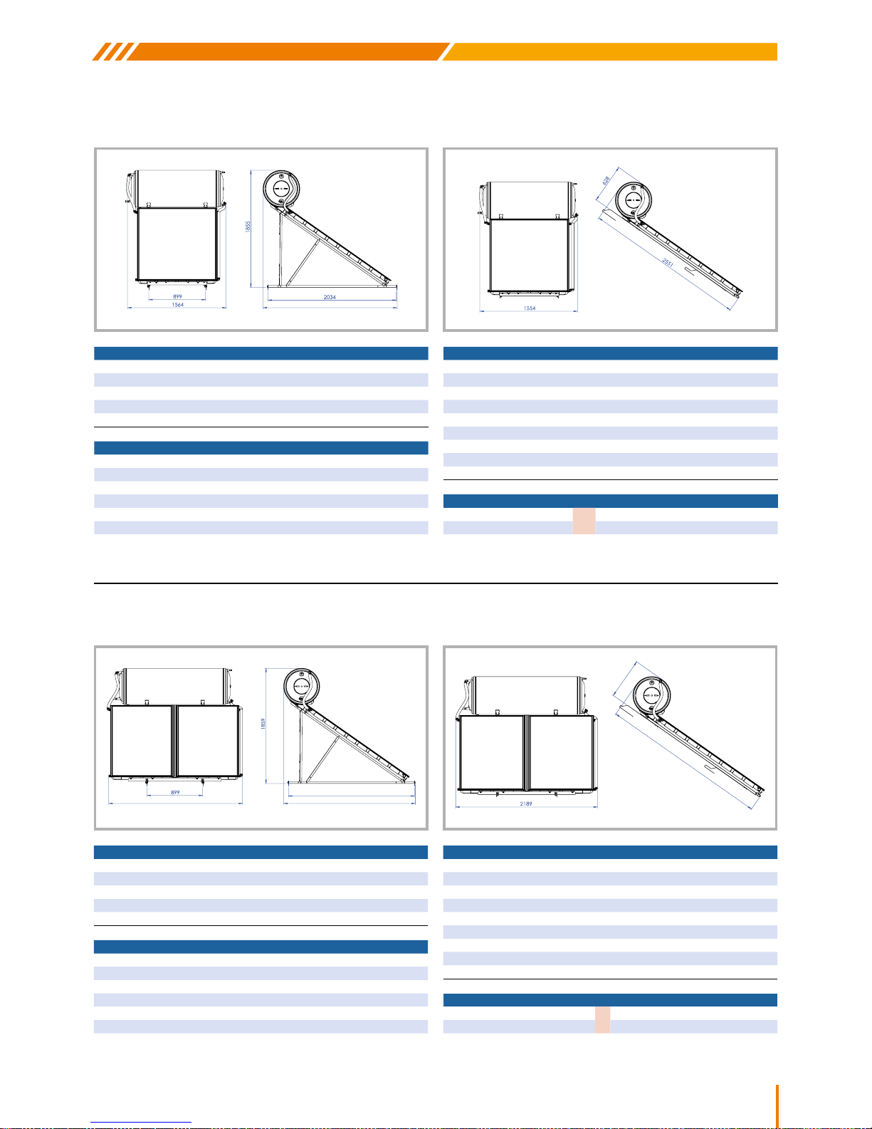
HYPERION 200lt/2.6m2 LAYOUΤ
Note: All dimensions measured in mm
COLLECTOR APOLLON AL 2600
TOTAL AREA (m²) 2.53
NUMBER OF MANIFOLDS 13
HEAT TRANSFER MEDIUM PROPYLENE GLYCOL SOLUTION
CAPACITY (lt) 2.12
ABSORBER SURFACE (m
2
) 2.30
TOTAL DIMENSIONS (mm) 2010x1260x110
COLLECTOR TOTAL WEIGHT (without liquid) (kg) 45.4
ABSORBER SELECTIVE ALUMINIUM
ABSORBENCY / RADIATION COEFFICIENT 95% ±2% / 5% ±2%
TOTAL SYSTEM HYPERION 200lt/2.6m
2
NUMBER OF COLLECTORS 1
SYSTEM WEIGHT EMPTY (packed) / FULL (kg) 158/363
MAX. WATER TANK OPERATING PRESSURE (bar) 10
CLOSED CIRCUIT MAX. OPERATING PRESSURE (bar) 3.5
MAX OPERATING TEMPERATURE 95°C
WATER STORAGE TANK 200lt
DIMENSIONS (mm) 580x1456
WEIGHT EMPTY (kg) (without packaging) 86.5
JACKET CAPACITY (lt) 20.4
JACKET SURFACE (m
2
) 1.42
MAX TEST PRESSURE (bar) 15
MAX OPERATING PRESSURE (bar) 10
HYPERION 200/2.6m2 - JACKET AND COLLECTOR CAPACITY: 21lt
ANTIFREEZE LIQUID (lt) 1 2 3 4 5 6 7 8 9 10
MIN. TEMPERATURE (
°
C) -2 -3 -5 -8 -10 -12 -15 -19 -23 -28
Note: All dimensions measured in mm
COLLECTOR APOLLON AL 2000
TOTAL AREA (m²) 2.03
NUMBER OF MANIFOLDS 10
HEAT TRANSFER MEDIUM PROPYLENE GLYCOL SOLUTION
CAPACITY (lt) 1.75
ABSORBER SURFACE (m
2
) 1.81
TOTAL DIMENSIONS (mm) 2010x1010x110
COLLECTOR TOTAL WEIGHT (without liquid) (kg) 38
ABSORBER SELECTIVE ALUMINIUM
ABSORBENCY / RADIATION COEFFICIENT 95% ±2% / 5% ±2%
TOTAL SYSTEM HYPERION 250lt/4m
2
NUMBER OF COLLECTORS 2
SYSTEM WEIGHT EMPTY (packed) / FULL (kg) 212.5/471.5
MAX. WATER TANK OPERATING PRESSURE (bar) 10
CLOSED CIRCUIT MAX. OPERATING PRESSURE (bar) 3.5
MAX OPERATING TEMPERATURE 95°C
HYPERION 250lt/4.0m2 LAYOUΤ
WATER STORAGE TANK 250lt
DIMENSIONS (mm) 580x1786
WEIGHT EMPTY (kg) (without packaging) 107.2
JACKET CAPACITY (lt) 27.5
JACKET SURFACE (m
2
) 1.9
MAX TEST PRESSURE (bar) 15
MAX OPERATING PRESSURE (bar) 10
HYPERION 250lt/4m2 - JACKET AND COLLECTOR CAPACITY: 28lt
ANTIFREEZE LIQUID (lt) 1 2 3 4 5 6 7 8 9 10 11 12 13 14 15
MIN. TEMPERATURE (
°
C) -1 -3 -4 -5 -6 -8 -9 - 11 -13 -15 -17 -20 -23 -26 -32
2126
FLAT SURFACE INCLINED SURFACE
2034
2125
2161
2553
632
FLAT SURFACE INCLINED SURFACE
Page 8
8
SWH/HYPC/ENER
2034
FLAT SURFACE INCLINED SURFACE
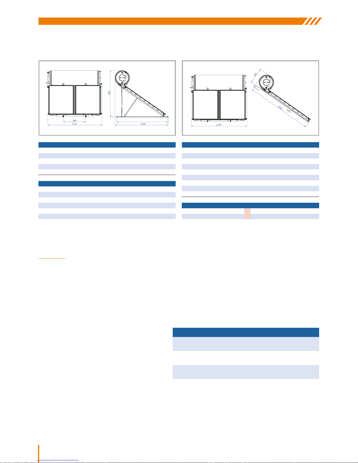
Note: All dimensions measured in mm
COLLECTOR APOLLON AL 2000
TOTAL AREA (m²) 2.03
NUMBER OF MANIFOLDS 10
HEAT TRANSFER MEDIUM PROPYLENE GLYCOL SOLUTION
CAPACITY (lt) 1.75
ABSORBER SURFACE (m
2
) 1.81
TOTAL DIMENSIONS (mm) 2010x1010x110
COLLECTOR TOTAL WEIGHT (without liquid) (kg) 38
ABSORBER SELECTIVE ALUMINIUM
ABSORBENCY / RADIATION COEFFICIENT 95% ±2% / 5% ±2%
TOTAL SYSTEM HYPERION 300lt/4m
2
NUMBER OF COLLECTORS 2
SYSTEM WEIGHT EMPTY (packed) / FULL (kg) 221/532
MAX. WATER TANK OPERATING PRESSURE (bar) 10
CLOSED CIRCUIT MAX. OPERATING PRESSURE (bar) 3.5
MAX OPERATING TEMPERATURE 95°C
HYPERION 300lt/4.0m2 LAYOUΤ
WATER STORAGE TANK 300lt
DIMENSIONS (mm) 580x2076
WEIGHT EMPTY (kg) (without packaging) 119.7
JACKET CAPACITY (lt) 25.8
JACKET SURFACE (m
2
) 1.79
MAX TEST PRESSURE (bar) 15
MAX OPERATING PRESSURE (bar) 10
HYPERION 300lt/4m2 - JACKET AND COLLECTOR CAPACITY: 30lt
ANTIFREEZE LIQUID (lt) 1 2 3 4 5 6 7 8 9 10 11 12 13 14 15
MIN. TEMPERATURE (
°
C) -1 -3 -4 -5 -6 -8 -9 - 11 -13 -15 -17 -20 -23 -26 -32
GENERAL INSTALLATION RULES
WARNING! The installation of the system must be in strict compliance with all local statutory regulations (I.E. building, plumbing,
electrical, urban, health & safety legislation etc.) & by authorized solar specialist installers only. Standards may vary from region to
region. Please be aware that compliance is the sole responsibility of the installer/s in contract & agreement with the owner/s of the solar
water heating system. Any non-compliance with the aforementioned or deviation from the recommended installation parameters set out
below, with or without due consideration to the above, may annul the warranty & no claim could be made against the companies for any
consequences caused by any event or circumstance whatsoever.
INSTALLATION LOCATION: Before an installation, the selection of a suitable location must be agreed upon by the installer in
consultation with the owner for the safe & effective operation of the system. The routing of the piping, the consequences thereof & future
ease of access for routine cleaning & maintenance should also be thoroughly considered.
SUPPORT STRUCTURE: It is imperative that the surface
of the systems’ intended position & its support structure
are assessed by a competent person by taking the static
resistance capacities & variant load bearing capabilities
into consideration. In particular the effects of extra added,
permanent deadweight & maximum wind/snow loads at the
point of installation need to be regarded. Where inadequate
bearing capacity is apparent, a correct installation would
require the competent bracing & strengthening of such a
structure compliant with local building regulations to ensure
the safety of the building, its occupants & their belongings. Although functional on most surfaces, in the event that there is no compatibility
between the equipment provided & the structure where the solar water heater is to be installed (inclined or at), then a custom kind of
equipment or structure would naturally be required. The sole responsibility for the materials, equipment chosen & the installation thereof
lies on the installer, proposed to & agreed upon with the owner prior to installation of the system.
APOLLON AL COLLECTOR
INSTALLATION MODE
WIND LOAD
[km/h] / [kΝ/m
2
]
SNOW LOAD
[kΝ/m2]
Inclined surface
(Inclination angle: 15° – 75°)
151 / 1.1 1.25
Flat surface
(Inclination angle: 35°)
151 / 1.1 1.25
Τhe system may only be installed in locations with lower wind and snow load values
than the ones mentioned above.
Page 9
9
SWH/HYPC/ENER
SOLAR WATER HEATERS
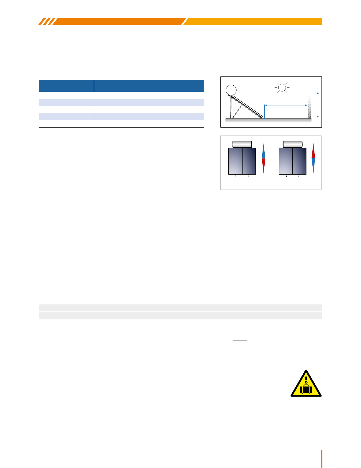
SHADING: The system should not be shaded by any obstacles for at least 6 (six) hours during midday hours to ensure that uninhibited
& direct exposure of the collectors to the sun is achieved over this daily timeframe. This is when solar irradiation & the systems’ energy
capture capability is at its peak (typically between 09.00 & 15.00 hours). Heavy dust & other deposits can effectively “shade” your panels
& thus should always be kept clear of any foreign materials.
OPTIMUM ORIENTATION TO THE SUN: A basic factor for the system’s
optimum performance is the selection of its collector angle and orientation for
its particular location (latitude), to ensure that the maximum daily energy gain is
acquired. The system should be positioned so that the collector’s surface faces
geographical south if the installation takes place in the Northern Hemisphere
(and geographical north for the Southern Hemisphere), i.e. for best results the
system should always face directly towards the Equator.
Any deviation in direction would mean a reduction in the system’s performance proportionate to the extent of the deviation. If a signicant
change from the proper orientation cannot be avoided then, following an evaluation of the specic conditions that apply, the system’s
performance may be increased & thus made viable by enlarging the area of the collector surface accordingly. Due to the attack or angle
of the sun’s rays varying from one season to the next, the collectors should be angled at a value approximately equal to the location’s
latitude +10 degrees. As the angle of attack on the system is xed, this orientation rule of thumb maximizes the energy gain on an overall
annual basis. Typically, areas of high irradiation have less need for absolute accuracy in this regard.
ANTI-FREEZE LIQUID: The heat transfer medium used in the closed circuit protects the system from freezing and from the
accumulation of salts inside the collector tubes & jacket. The thermal uid must be well mixed with water in a percentage that is
necessary to protect the system against expected local weather & environmental extremes. The responsibility for the appropriate mix
of glycol to quantity of water for the anticipated conditions as well as for the quality of liquid used other than the one supplied with the
solar water heater lies solely on the installer and/or the owner of the system. The liquid provided is an advanced, food grade propylene
glycol based product that is formulated to ensure effective heat transfer properties at both high & low temperatures. It is non-toxic and
provides protection up to -37°C (solution 55% v/v with water). It is especially designed to provide excellent anticorrosion properties. The
glycol offers freeze protection according to dilution as per the table below:
EXTREME WEATHER & ENVIRONMENTAL CONDITIONS: It is highly recommended that you insure your solar water heater
against the same possible extreme or freak weather events as you would do for your home before installing the system. Regions with
heavy storms, high wind velocity, cyclones, tornadoes, hail of more than 20mm in diameter or dry areas prone to bush/forest res
might require special insurance to assure you of your asset. Heavy snow precipitation should be removed without delay. It is also
recommended that an effective water ltration system be installed in hard water regions to alleviate an intensive maintenance regime.
SYSTEM HANDLING: To safeguard the device from damage, the solar system’s protective packaging should only
be removed once on site & just prior to the installation. Due care & consideration needs to be exercised when storing,
transporting & unpacking the product. Ensure the product is free of all polystyrene packaging before removing the
plastic protective caps from the water storage tank and the collector pipe ends. The collectors & water tank are never
to be lifted by or supported on their pipes. To prevent the risk of thermal shock to the water frame, pre-mature boiling
of the heat transfer liquid or any incidental breakages - the collector’s glass must remain covered with a suitable material until the
installation is completed in its entirety. Due to its bulk, weight & fragile nature of the enamelling, the safe lifting & mounting of the water
tank will require either the use of a mechanised or manually operated geared lifting device appropriate for the weight being manipulated
or alternatively, manual handling is only possible with industrial grade ladders, stable scaffolding & adequate numbers of personnel.
Safety ropes, pulleys & harnesses for both the boiler & the workforce would need to be employed. Careful pre-planning & people
management is imperative for the safe positioning of the water tank.
L
H
LATITUDE
DISTANCE BETWEEN THE OBSTACLE
AND THE COLLECTOR (L)
0°
- 25° 1.0 x H
26°
- 35° 1.5 x H
36°
- 45° 2.0 x H
46°
- 50° 2.5 x H
> 50
o
3.0 x H
N
S
N
S
Northern Hemisphere Southern Hemisphere
PERCENTAGE (%) 5 10 15 20 25 30 35 40 45 50
TEMPERATURE (°C) -2 -4 -6 -8 -11 -15 -19 -24 -30 -37
Page 10
10
SWH/HYPC/ENER
PERSONNEL REQUIREMENTS: The installation of the Nobel solar water heating systems may only be undertaken
by authorized solar qualied companies and their trained personnel. Works in electrical installations or conductors
may only be executed by trained & qualied electricians. Certicates of compliance (coc’s) should be available to the
owner from both the plumbing & electrical contractors respectively.
GENERAL SAFETY MEASURES
y Always clearly demarcate & keep clean both the access to, & the immediate area surrounding the work place. Ensure that it is kept
clear of any objects that may obstruct any movement of personnel and/or equipment during the execution of the installation
y Do not allow pets or any unskilled, unauthorized or inappropriately dressed persons into, near or underneath the demarcated work
area. To come in contact with any tools, solar water heater components, building materials, or the antifreeze liquid at any time
y Do not use any but the appropriate tools, accessories & components, only for the function for which they are intended & without
compromise when installing the solar water heater. The use of inappropriate tools & accessories can damage components, cause
accidents and/or injury
y All personnel involved shall wear the appropriate labour uniforms, notably; safety shoes, hard hat, hair net (if required), Hivisibility
reective jacket, safety harness & ropes for any work above head height, safety glasses, tool belts & gloves. Also refrain from
wearing baggy clothing or jewellery
y A comprehensive anti-burn & general rst aid kit should be kept on hand at all times. If glycol comes into contact with the eyes, ush
with copious amounts of water & seek immediate medical attention. Do not ingest glycol
DANGER!
Men at work
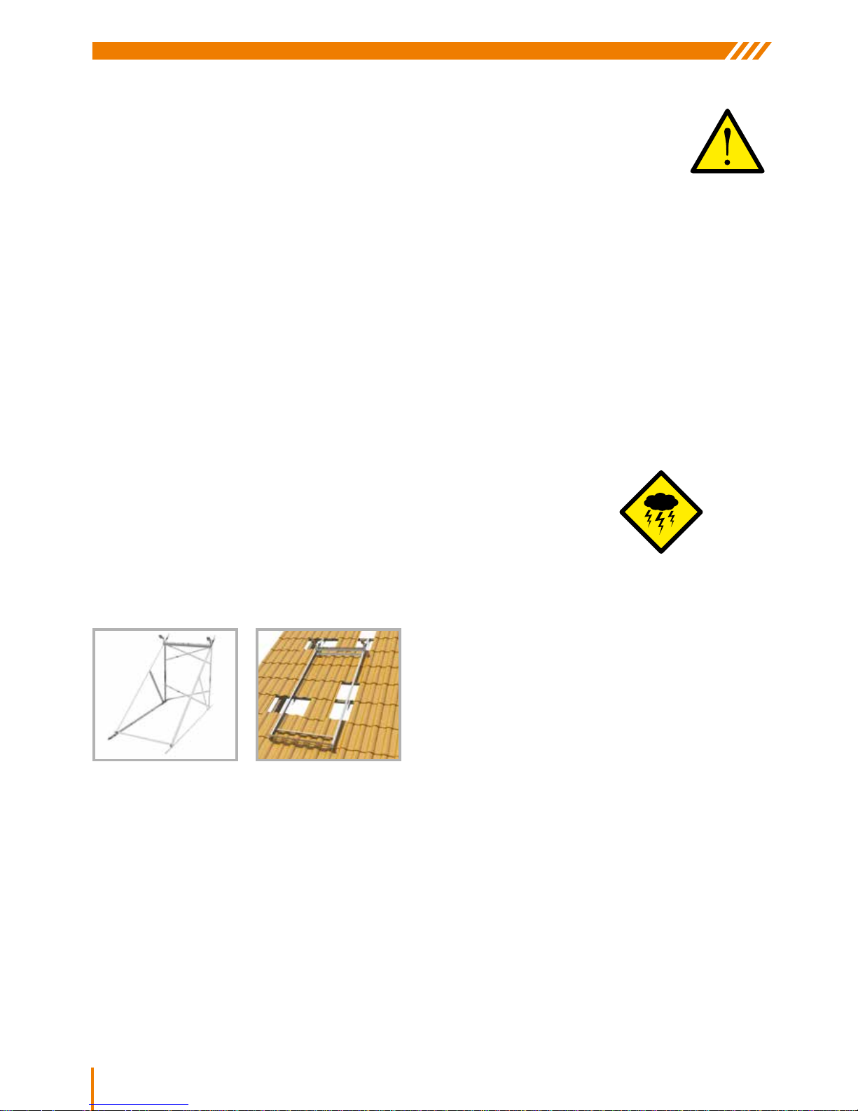
LIGHTNING PROTECTION
The metal construction conforms to the general & special requirements of the ELOT 1197 Standard.
SUPPORT BASE
One type of supporting base system, made of 2.5mm thick galvanized steel, for installation on at or inclined surfaces.
Page 11

11
SWH/HYPC/ENER
SOLAR WATER HEATERS
6
0
15
55
490
925
965
980
7
8
15
16
For inclined surface OPTION A
For inclined surface OPTION B
SUPPORT BASE PARTS
For 1.5m2 collector
Page 12

12
SWH/HYPC/ENER
For 2.0m2, 2.6m2 & 4.0m2 collectors
0
10
110
815
915
925
0
11,5
38,5
342,5
847,5
1151,5
1178,5
1190
0
134
204
944
2168
2208
2238
2250
279
0
13
173
213
308
1752
1847
1887
2047
2060
1
2
3
4
6
5
0
15
55
490
925
965
980
7
8
5
15
16
For 4.0m2 collector (2 x 2.0m2)
For 2.0m
2 &
2.6m2 collector
For inclined surface OPTION A
For inclined surface OPTION B
Page 13

13
SWH/HYPC/ENER
SOLAR WATER HEATERS
60mm
ASSEMBLY ON A FLAT SURFACE
1. Attach parts 1 to 2 using the M8 nuts & bolts supplied
6. In the case of two collectors; place the rst collector
intoposition, line up the threaded holes in the panels
to bolt slots in the frame & lightly secure with bolts &
washers supplied
7. Put the 22mm compression brass unions onto the inner
collector pipes, place 2nd collector. Line up & secure both
collectors rmly with bolts & washers, tighten brass unions
4. Attach parts 6 as cross bracing to bring the two halves
of the frame together
3. Position part 4 to triangulate the frame & repeat steps 1,
2, & 3 to create a mirror image of the rst part of the frame
5a. Place 1st part 5 (panel bar)
to the bottom of the frame as
shown & tighten all nuts & bolts
in position so far
5b. Place 2nd part 5 at the top of
the frame as shown, tighten
bolts once panels are properly
positioned & secured
2. Complete triangle by attaching part 3 as shown
2
1
3
4
6
5
5
Page 14
14
SWH/HYPC/ENER
STEP 9
STEP 17
STEP 11
STEP 15
STEP 13-14
8. Bolt the water tank cradles (part 7) into position as shown, orientate the frame to the compass point required & secure frame rmly
in with M8 x 60mm bolts & plugs supplied
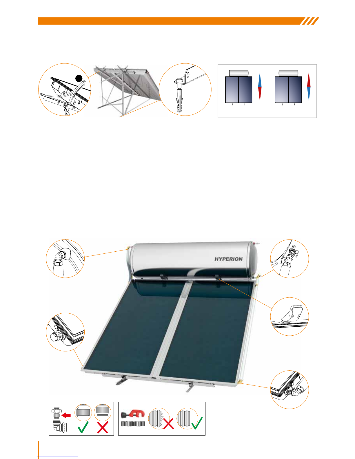
1. Place and tighten the Ø22 mechanically tightened plugs on the top right and on the bottom left of the collector/collectors*. Place
the water storage tank on the base with its electrical components to the left when viewing the water storage tank from the front
2. Centre the water storage tank’s position in respect to the collector/s. Rotate the water storage tank (if necessary) to ensure that the
cold and hot potable water sockets are positioned vertical or 90 degrees to the horizontal surface. Secure the water storage tank
onto the base using the screws provided. Ensure the appliance is not tilted and is properly levelled
3. Place & tighten the short exible tube using the DN16 INOX female connector on to the socket marked “collector intake”
4. Fit UV protected insulation on to the tube & join the other end to the top left socket of the collector using the Ø22xDN16 INOX
corner tting
5. Fit the T-piece with the lling valve to the socket on the right side of the water storage tank marked “collector return”
6. Fit the long exible tube with the special connection to the T-piece on the right side of the water storage tank
7. Fit insulation as before & x the other end at the bottom right socket of the collector using the Ø22x DN16 INOX corner tting
8. Fit water tank cradle covers
N
S
N
S
Northern Hemisphere Southern Hemisphere
7
Page 15

15
SWH/HYPC/ENER
SOLAR WATER HEATERS
ASSEMBLY ΟΝ ΑΝ INCLINED SURFACE
5. Either bolt straight straps directly into
and/or bend the straight parts 6 over the
preprepared support beams & bolt the loop
created together (supports for mounting
must comply with mandatory local building
standards). Drill and mechanically tighten
bolts to maximum torque. Use a spirit level
to ensure the system is plumb
1. Bolt a part 1 to a part 2 using the M8 nuts & bolts supplied. Repeat to construct a mirror image of the rst pair of parts as shown
1
2
2
1
2
1
4
6
2. Place a part 4 between the “U” shapes constructed above into the positions shown below. Place a part 6 under
the “U” & x with M8’s supplied, repeat procedure to construct the rectangular “H” frame pictured on right
5
5
3. Attach the collector supporting
panel bar, part 5, to the bottom
part of the frame and tighten all
nuts & bolts in position so far
4. Place the other panel bar into
position at the top of the frame as
shown, tighten bolts once panels
are properly positioned & secured
OPTION A - Using part 6
Continue on step 6
Page 16

16
SWH/HYPC/ENER
SOLAR WATER HEATERS
ASSEMBLY ΟΝ ΑΝ INCLINED SURFACE
1. Bolt a part 1 to a part 2 using the M8 nuts & bolts supplied. Repeat to construct a mirror image of the rst pair of parts as shown
1
2
2
1
2
1
OPTION B - Using parts 15-16
2. Place part 4 included in the packing of the base between the two Π shapes made in the previous step. Place part 15 exactly
underneath. Screw in the screws and nuts included in the packing. Repeat the same with the second pair of parts
15
4
3. Screw part 5 of the collector support at the
bottom of the frame and tighten the screws.
4. Screw part 5 of the collector support at the top
of the frame without tightening the screws.
5
5
5
Page 17

17
SWH/HYPC/ENER
SOLAR WATER HEATERS
7. Put the 22mm compression brass unions onto the inner
collector pipes, place 2nd collector. Line up & secure both
collectors rmly with bolts & washers, tighten brass unions
8. Bolt the water tank cradles (part 7) into position as shown
below
60mm
9. Place and tighten the Ø22 mechanically tightened plugs on the top right and on the bottom left of the collector/collectors*. Place
the water storage tank on the base with its electrical components to the left when viewing the water storage tank from the front
10. Centre the water storage tank’s position in respect to the collector/s. Rotate the water storage tank (if necessary) to ensure that the
cold and hot potable water sockets are positioned vertical or 90 degrees to the horizontal surface. Secure the water storage tank
onto the base using the screws provided. Ensure the appliance is not tilted and is properly levelled
11. Place & tighten the short exible tube using the DN16 INOX female connector on to the socket marked “collector intake”
12. Fit UV protected insulation on to the tube & join the other end to the top left socket of the collector using the Ø22xDN16 INOX
corner tting
13. Fit the T-piece with the lling valve to the socket on the right side of the water storage tank marked “collector return”
14. Fit the long exible tube with the special connection to the T-piece on the right side of the water storage tank
15. Fit insulation as before & x the other end at the bottom right socket of the collector using the Ø22x DN16 INOX corner tting
16. Fit water tank cradle covers
6. In the case of two collectors; place the rst
collector into position, line up the threaded
holes in the panels to bolt slots in the
frame & lightly secure with bolts & washers
supplied as shown below left
5. Screw the four coach screws 16 in corresponding holes (see 5.1 or 5.2) of the parts 15 on robust interior post tile roof. Give the
desired angle and tighten the base onto coach screws 16 with the nuts M12 and washers (5.3)
16
5.2
15
16
5.3
15
Common steps for both options A & B
Page 18

18
SWH/HYPC/ENER
STEP 11
STEP 9
STEP 15
STEP 17
STEP 13-14
Page 19

19
SWH/HYPC/ENER
SOLAR WATER HEATERS
ANODE
(Replacements available exclusively from Nobel)
Remove electrical component housing cover & element ange. To t
the magnesium anode, place the anode with 22mm threaded bolt &
washer attached into the 22mm port in the centre of the tank opposite
the electrical cover as shown. The weight & length of the anode requires manually supporting the anode from the ange end of the tank
to avoid double threading the bolt. Once the anode is suitably braced,
tighten the bolt. For dual anode protection, simply screw on regular
anode to the element ange supplied.
ELECTRICAL CONNECTION
CONNECTING: Heating element & thermostat supplied.
ACCESSORIES: Suitable isolator switch in weather
proof box, properly rated power cable, appropriate circuit
breaker, earth bonding strap, timer and/or TD controller,
(optional).
GENERAL RULES: Electrical installation &
commissioning of the solar water heater may only be
carried out & signed off (coc), by a legitimately qualied,
registered electrician and in strict accordance with the
national electrical & building regulations applicable to
the system’s permanent location. The power to the
heating element must never be switched on when there
insufcient water in the water storage tank. In such
aninstance the heating element warranty will not apply.
ELECTRICAL COMPONENTS (Heating element - Thermostat)
NOTE:
The supplied heating element’s KW rating depends on tank volume & local regulations of the country of destination. Switch off
the central mains switch before commencing installation.
A
C
B
D
Remove the screws & protective cover to expose the element
ange (A). Seat element onto the rubber seal & secure to the steel
ange with bolt supplied. Align components as shown below & bolt
assembly back on to the boiler (B).
Push the end of the cable through the gland under the tank and into the electrical component housing (C). Ensure
the thermostat is securely inserted into the element sockets. Connect the red wire (Live) to the connector “L”, the
black wire (neutral) to the connector “N” on the thermostat & connect the earth wire to the small M4 screw on the
heating element ange marked with the ground symbol (D). Set thermostat to desired max temperature, replace
protective cover & tighten cable gland. Connect the other end of the cable to the electrical distribution board via an
isolator positioned not further than arm’s length from the element. Use a bipolar disconnection switch with a minimum
distance between contacts of at least 3mm. The circuit breaker’s rating, along with any timers or TD controllers
installed, must be suitable for the rating of the heating element & electrical supply in use.
HEATING ELEMENT
Thermostat
Temperature
Regulator
(40-80°C)
Earthing
L = Phase
N = Neutral
DANGER!
Electric shock
risk
Page 20

20
SWH/HYPC/ENER
HYDRAULIC CONNECTION
GENERAL RULES: The hydraulic coupling & commissioning of the solar water heater to any cold water supply mains &/or hot water
distribution network may only be carried out & signed off (coc), by a legitimately qualied, registered, solar qualied plumber in strict
accordance with the national building regulations applicable to the installation’s permanent location.
CLOSE LOOP FILLING
WARNING! Before lling the closed loop (collectors & jacket) with the anti-freeze / water solution, make sure that the potable water
storage tank is completely plumbed, lled with water & pressurised. Always keep the collectors covered/shaded throughout the duration
of the installation to ensure the collectors are kept cool before & whilst lling. Never leave the collectors exposed in an un-commissioned
installation. The water heaters are supplied with a nominal minus (-) 5 degree frost protection. Glycol to water ratios need to be adjusted
& supplied by the contractor for adequate protection in areas prone to lower environmental temperatures, (see table on page 9). If in
doubt - always err on the side of caution, failures due to freezing of the jacket or collectors are not covered by the system warranty.
(Using distilled or boiled & ltered water in known hard water areas is highly recommended).
1. Check the closed loop’s liquid capacity on the system layouts printed in this manual for the relative
size of the system installed
2. Thoroughly pre-mix all the glycol supplied (plus extra if required), with the requisite volume of clean
soft potable water to ll the system. Use an appropriately sized container tted with a drain tap &
exible hosepipe
3. Place a suitable, non-slip protective cover over the tank & hold the solution lled container in a stable
position on top of the tank directly above the jacket expansion port
4. Connect the hose from the container to the lling “T” installed on the tank jacket outlet
5. Ensure that the safety valve is off the jacket
expansion port, open the taps on rst the
container & then the lling “T”. Allow the
glycol solution to gravity feed into the system
6. Once 80 to 90 % of the liquid has “dropped” into the loop, lift up the
container slightly to ensure that the drain tap on the container is clearly
above the expansion port
7. Once the liquid starts spilling out of the expansion port, the jacket is full.
Immediately close the tap on the lling “T” & container respectively
8. Remove the hose from lling “T” & t the safety expansion valve in position
as shown
Insulate & UV proof all
exposed piping & components
PRV valve with safety expansion
“balanced pressure”
Banjo T/P valve
Drain cock
Cold
Hot
Tempering
valve
Copper
bonding
Vacuum
breakers
T/P safety
discharge
Connections to the tank sockets must be by union type nuts, never
solder. Hot water piping must be suitable for temperatures up to 120
degrees C. All temperature & pressure relief safety valves must be
piped to a safe discharge location with suitably rigid, heat & pressure
tolerant materials. All exposed piping to & from the system must be fully insulated & UV protected. A tempering valve with cold water supply
shall be tted to the hot water line to prevent scolding. A pressure regulating valve shall be installed to the mains before entering the building
to balance the hot & cold distribution network. Any regulating, check,
non-return or service valves on the cold water supply feeding the water heater requires compulsory, downstream expansion protection. An
inline strainer is recommended for borehole water.
The 22mm threaded “COLD WATER INLET” and “HOT WATER OUTLET” sockets are marked on the tank &
coloured blue (COLD) and red (HOT). Fit a drain cock & hot water safety valve to the COLD inlet & HOT outlet on
the tank respectively. Plumb anti-syphon loops with vacuum breakers to both the hot & cold lines connected to the
tank. Fit a thermostatic tempering valve to supply cold water into the hot line when required before distribution.
Bond hot to cold water piping with copper strap. Once plumbed, open hot tap/s & then the water mains supply to
ll the tank with water. Once a steady ow is achieved at the tap/s, close off the ow & inspect plumbing for any
leaks. Pressure test conrmed, install safety discharge pipes to safe location, fully insulate & UV protect all piping.
ANTIFREEZE
FILLING
Page 21

21
SWH/HYPC/ENER
SOLAR WATER HEATERS
SYSTEM WITH THE WATER STORAGE TANK UNDER THE ROOF
CIRCULATION PUMP MAIN FEATURES
9. Uncover the collectors and clean the glass, ensure to remove all the information stickers. Check to make sure that all pipe joints
are leak free & insure piping is left suitably insulated
10. Clean-up & clear away all tools, materials & scaffolding etc. before opening access to the demarcated work area
11. After the initial completion of the installation, no hot water should be consumed for the rest of the day in order for the closed loop to
be properly energised. Auxiliary power backup may be required for the rst evening’s consumption if the system is commissioned
late in the day or inclement weather is experienced. It can take up to 2 days of operation in favourable conditions before the system
settles down into performing optimally
8°
Natural circulation operation Forced circulation operation
For the optimum efciency using natural thermosyphon
circulation, the maximum and minimum distances as well
as the angles for the piping must always be respected.
The maximum distance between the collector outlet and
the water storage tank inlet must not exceed 3m in length.
The angle of the pipe joining these 2 points must not be
less than 8° (degrees). The vertical distance between
the top of the collector & bottom of the water storage tank
must be a minimum of 300mm. The tank shall be tted
with a drip tray & piped safely out of the building along
with all safety discharge piping. Installation shall comply
with local statutory building standards pertinent to hot
water tanks positioned indoors and/or in roof cavities
During the day, once adequate solar irradiation is available, the photovoltaic generator
produces direct current which it supplies to the electric pump. The pump allows
the circulation of the heat transfer liquid between the solar collector and the heat
exchanger of the water tank. This constant circulation of the heat transfer medium
between collector and tank leads to the steady, gradual heating of the water within the
storage tank. During the night or when adequate irradiation is unavailable during the
day, the photovoltaic generator does not produce electric current and thus the pump
immediately stops its operation avoiding the aimless circulation of the heat transfer
medium. This system is extremely simple and economical since there is no need for
many components required of conventional pumped systems (differential thermostats,
regulators, non-return valves, temperature sensors, heat dumps, extra expansion
tanks or safety valves) for its operation and that is why minimum maintenance or
regulation works are required. Moreover, there is no delay phenomena (Which occurs
in conventional pumped systems), since, when there is sufcient sunlight for the pump
to operate, It immediately exchanges any available energy the collector produces &
thus results in very stable operating parameters that promote consistency, reliability &
system longevity unattainable in orthodox pumped systems.
MAX. DISTANCE 3m
MAX. ANGLE 8°
MAX. DISTANCE 5m
PUMP &
NON RETURN
VALV E
PHOTOVOLTAIC
PANEL
COLLECTOR OUT COLLECTOR IN
Dual collector hydraulic conguration
for forced circulation (pumped) systems
(Joined by a single union only, at the bottom of collectors)
y Voltage 6V ≈24V DC (Rated: 12V DC)
y Max working temperature: 110 °C (230 °F)
y Max system pressure: 10 bar
y Low noise: ≤45Db far from 1m distance
y Long life brushless pump with energy efciency
technology
y Soft start at very low in-rush current, good
convenient working directly with PV panel
y Mini start-up power consuption less than 2W
y Advanced magnetic drive technology for static
impeller, without any leakage
y Durable permanent magnetic rotor/impeller and
ne ceramic shaft
y Heavy duty work, can sunstain continual 24
hours’ waork
y Low power consuption, low or no maintenance
Page 22

22
SWH/HYPC/ENER
POST INSTALLATION INSTRUCTIONS
Before using the system make a nal check. Check all the valves and inspect the complete system including the water supply & distribution
plumbing for any kind of leakage. Repeat the inspection after one (1) hour of direct midday irradiation. Following its installation, the solar
water storage tank needs about 2 days of adequate irradiation to achieve its maximum efciency. For this reason it is recommended that
either one refrains from consuming hot water or at least keep the auxiliary electrical backup on permanently during the rst two days of
operation. Optimum performance requires abstaining from using hot water during solar heating hours. The collectors are self-cleaning
during a regular rainy season but would require systematic cleaning to prevent dust build-up on the glass in the dry season. Spray down
collectors at least once a week in dry conditions taking care to do so only during the early morning or evening to avoid causing any
damages due to sudden extreme temperature changes. To ensure consistent optimum performance in high irradiation areas, the level
of antifreeze in the closed circuit may need topping up annually (preferably in early autumn after the maximum expansion that summer
irradiation levels inict on the closed loop is over). A “bubble tank” extension to the jacket can be employed to minimise glycol losses
caused by high irradiation or low water consumption on the system. During long periods of time where no hot water is required (e.g. during
the summer holidays), it is recommended that the collector surface is covered with an opaque cover in order to avoid overheating the
potable water or closed loop liquids. The build-up of high pressure & temperatures in the water tank is regulated by the normal function of
the safety valves which will open and discharge water to protect the system if required. If the mains pressure exceeds 400 KPA a pressure
reducing valve must be installed on the cold water feed. Never switch on the electrical heating element if there is no ow of hot water
through the vessel. Always re-heat potable water to a min. 60 degrees after long system inactivity to prevent bacterial infections.
WARNING! The System must be tted with a thermostatically controlled tempering valve to protect against water
scolding, should a sudden marked increase in the temperature of the water become apparent, refrain from direct
contact with hot water & call a technician to inspect the system immediately. Seek immediate professional medical
attention In the event of physical trauma caused by exposure to hot water.
For optimum performance & importantly, for the solar water heater’s warranty to apply, the system must be serviced at
least every two (2) years by an authorised technician with the relevant plumbing & electrical qualications. Please read
the terms & conditions laid out in the Nobel/Enerjetic warranty in this document for area specic statutory maintenance
regimes. Once serviced, the system should be left in full & effective operational readiness as per the requirements of
the original installation. Particular attention needs to be paid to the following:
It is highly recommended that the Water storage tank is thoroughly ushed out every four to six (4 - 6) years to clean out all the mineral
deposits that collect in the tank over time. Maintenance is best done early mornings to minimise consumption disruption & risk of injury
due to hot components. Appropriate regulatory safety apparel & procedures are mandatory when servicing a solar water heating system.
It would require at least two (2) technicians to effect a safe service. All the solar water heater service data must be recorded on the chart
provided on the last page of the warranty document.
PROCEDURE: Clear & demarcate a public exclusion area around the work zone & set up safe access to the system. Shut down the
electrical power supply at the isolation switch and the distribution board. Do a preliminary inspection on all the piping & safety valves for
any leaks or unwarranted discharge before shutting off the water mains supply to the system. Cover the collectors & keep them shaded
for the duration of the service.
Un-screw the closed loop expansion valve (gradually to relieve pressure slowly), re-tighten temporarily. Un-couple the bottom left plug on
the collectors & place a funnel & hose to collect the glycol mixture into a suitable heat resistant container for later safe disposal. Unscrew
the expansion valve again, set aside & allow closed loop to drain. Connect a pressure hose to the expansion relief port on top of the tank,
ll closed loop gently with water, increase pressure & ush thoroughly with clean water until clear. Allow to drain out the bottom of the
collector. Open the hot tap & drain the water from the tank via the drain cock, direct water to a safe dump location with a hose. Remove
electrical cavity cover, disconnect earth wire & thermostat, remove element ange. Un-couple the hot & cold water pipes & rotate the tank
in the cradle so the hot out port is now positioned at the “bottom” of the tank. Flush out tank with a pressure hose until vessel is clear of
all mineral deposits. Turn the tank back the right way up & re-secure in original position. Replace any of the safety valves if required at
this stage.
Check element for scale build-up & replace if necessary. Remove & replace element ange anode (if utilised). Un-screw the 22mm
main anode lug & remove old anode. Un-screw old anode from lug & replace with new one. Insert the new anode into the tank & have it
supported from the ange end of the tank to avoid double threading the bolt. Once the anode is suitably braced, tighten the bolt to secure.
Replace element ange, re-connect thermostat & earth wire.
DANGER!
Hot water
SERVICE - MAINTENANCE
1. Flange & seal
2. Safety valves
3. Element & thermostat
4. Piping & ttings
5. Insulation
6. Support structure
7. Anode replacement
8. Glycol replacement
Page 23

23
SWH/HYPC/ENER
SOLAR WATER HEATERS
IF THE SYSTEM DOES NOT HEAT WATER WHEN USING THE ELECTRICAL HEATING ELEMENT:
Only a qualied electrician may perform the following procedures:
TROUBLESHOOTING
IF THE SYSTEM SUPPLIES AN UNSATISFACTORY AMOUNT OF SOLAR HOT WATER:
Assuming the solar water heater is efciently managed, correctly sized, orientated & properly installed then:
Inspect the installation for any possible structural degradation & conduct any remedial repairs required to the system support assembly
before re-lling the water tank. Re-couple the mains & distribution piping to the water tank, Open water mains & ll the tank, close tap
once full. Ensure element ange, safety valves, piping & connections have no leaks once under pressure, replace collector plug & rell
the closed loop with a new Glycol solution as per the instructions laid out in this manual. Check the closed loop for leaks & inspect the
complete system for any degraded insulation & replace or repair accordingly. Inspect & ensure the complete electrical circuit remains
undamaged & in regulatory working order before switching back on the power supply & testing the element with a multimeter to ensure
all is well. Replace electrical cavity cover, uncover & clean the collectors. Ensure no new plant growth is a potential shade threat, inspect
the condition of the roof covering & repair any waterproong that may have been compromised during servicing operations. Satised that
all is in working order, dismantle demarcated area & leave clean & safe for public use. Record the completed service & book next service
date with the client. The same post installation instructions would apply to when the original installation was conducted.
1. Take the weather conditions into account when making a
judgement.
2. Take seasonal changes into account as well, winter ambient
water temperature combined with lower irradiation levels
effect daily results, especially with installations set up well
below the optimum winter absorption angle.
3. Take any recent increases or time changes in daily
consumption into consideration.
4. Is there constant draw off of hot water whilst the sun is trying
to heat the system?
5. Make sure your collectors have not become shaded by
obstacles like new buildings or recent plant growth.
6. Have any new plumbing points (taps, showers etc.) or new
water reliant appliances been added to the home since
installation?
7. Check the building’s piping and taps for the possibility of any
leaks that would cause constant water ow through the tank.
8. Check that the system is properly level.
9. Make sure none of the pipes between the collectors & tank
have become kinked.
10. Check all the unions on the system for leaks & tighten if
necessary.
11. Make sure there are no air-locks inside the closed loop.
12. Check the level of ant-freeze solution & top up if required.
13. Check for any calcite build up that may inhibit the natural ow
of liquid in the closed loop.
14. Check that the tempering valve is fully functional & is not
over-supplying cold water to the hot/cold mix.
15. If a pumped system, check the pump’s working condition,
power supply status & that the TD controller is correctly
programmed & functioning properly.
1. If the electrical backup is controlled by an electronic timer,
check that it is in good working order, properly connected &
set to times appropriate to accommodate the consumption
levels of the household.
2. Shut down the electrical power supply at the isolation switch
and the distribution board circuit breaker.
3. Remove the electrical component cavity cover, re-supply
the system with power & test voltage & current draw on the
thermostat & element with a multi-meter.
4. Check that the thermostat is set to an appropriate maximum
temperature.
5. Check that the thermostat pins are securely attached to the
element sockets & that no arcing has occurred.
6. Check for any water leaks from the element ange that may
be shorting out the thermostat terminals.
7. Check the entire length of the power cable for kinks or rodent
damage & that all component wiring connections from the
thermostat, through the isolation switch to the distribution
board circuit breaker & timer are properly attached & fully
functional.
8. Replace any of the electrical components if necessary &
retest the system to conrm all is operational.
9. If element replacement is required – follow the instructions in
the electrical connection section of this manual.
10. Only use national safety standard approved materials of
appropriate current rating when replacing any of the electrical
components.
11. Replace the component cavity cover & ensure to leave work
area free of any electrical debris & safe for public access.
DANGER!
Electric shock risk
Page 24

24
SWH/HYPC/ENER
POST INSTALLATION CHECKLIST
The installer must complete the checklist below by ticking the appropiate box & the warranty declaration thereafter,
in the presence of the customer, to declare that:
SOLAR WATER HEATER INSTALLATION Yes No
The system’s installation, including all materials & accessories comply with all relevant national standards.
The installation is complete & fully operational.
A plumbing certicate of compliance has been issued by a solar qualied plumber.
An electrical certicate of compliance has been issued by a qualied electrician.
The weight bearing support structure to which the system is xed is appropriately engineered & re-enforced
if required, to be safe & compliant with national building regulations.
The collectors are appropriately angled & orientated for suitable solar absorption.
Collector angle to the sun: Collector compass bearing:
The collectors are positioned to be shade free for at least six hours during peak irradiation times throughout
the year (typically between 09H00 & 15H00 hours daily).
The system has been pressure tested & deemed to be leak free.
All the system’s piping is appropriately insulated throughout & suitably UV protected where exposed.
An anti-scolding thermostatic tempering valve is tted to the system.
All roof penetration points are suitably sealed & waterproofed.
All temperature & pressure relief valves are suitably piped to discharge in a safe location.
The system installed, through consultation with the client, is properly sized & deemed sufcient for the
household’s requirements.
GENERAL OPERATION & MAINTENANCE Yes No
The client is properly informed with regard to the solar water heaters operation, its abilities, limitations & its
auxiliary backup’s operation of choice (i.e. heat pump, gas or electrical resistance).
The client understands the best ways and means of managing hot water consumption to capitalise on
maximising their energy saving benets.
The client has been fully informed with regard to routine cleaning & statutory maintenance regimes required for
optimum performance.
The client is fully briefed, aware of & understands all the terms & conditions concerning the warranty
of the system as well as the consequences of non-compliance thereof.
The client is fully briefed & has complete operational understanding of any auxiliary timers, booster switches
or TD controllers tted to the system.
The client has been briefed in best practise with regard to supporting temporary increased hot water demands
(visitors, laundry days etc.) and in systems that are left unused for extended periods of time (i.e. holidays).
The client and installer fully understand that this document constitutes a declaration of compliance.
Any decisions or actions resulting in regulations not being adhered to for any reason whatsoever will be solely
at the client’s own risk.
Page 25

25
SWH/HYPC/ENER
SOLAR WATER HEATERS
NOBEL INTERNATIONAL / ENERJETIC DISTRIBUTORS
CERTIFICATE OF GUARANTEE
This guarantee is underwritten by Enerjetic Distributors cc of 718 James Crescent, Halfway House, Midrand, South Africa.
TERMS & CONDITIONS OF THE GUARANTEE
y This certicate of guarantee applies solely to solar water
heaters manufactured by Xilinakis & Co, distributed by
Enerjetic Distributors South Africa & commissioned on or after
the 1st January 2014
y With this certicate, the companies guarantee the below
recorded Nobel Aelios water storage tank & Nobel Apollon
solar collector/s, installed solely in conjunction with each other,
against any manufacturing defects
y The above mentioned declarations are strictly subject to all
the terms & conditions detailed in this certicate of guarantee
y This guarantee is recorded by the company and is valid from
the date of purchase from Enerjetic Distributors
y This guarantee is limited to the replacement and/or repair of
defective parts free of charge on proviso, whilst the cost of
transport (When in excess of 30km from nearest authorised
dealer) would be for the customer’s account
y Enerjetic Distributors offers warranty claim service response
through its authorised dealer network subject to the terms and
conditions of this document
y For the guarantee to remain valid, it is mandatory for the
customer ensure that the recommended maintenance regime
is strictly adhered to by an authorised Nobel technician &
keeps a written record thereof
y The customer should keep all documents & purchase receipts
related to any repair, maintenance and/or replacement of the
system and its periphery components
y It is imperative that the required maintenance is carried out
every 18 - 24 months; (an obligatory requirement for a 10
year warranty), particular attention needs to be given to the
replacement of the magnesium anode/s, especially in known
hard water areas. Borehole & untreated water (high in soluble
minerals) should be ltered before entering the system & can
require servicing as regularly as every 6 (six) months. The rate
of electrical resistance heating is directly proportional to the
rate of anode depletion
y The routine maintenance/inspection expenses are charged to
the owner of the solar system
y In the event of a suspected failure, the client should contact
& inform their installer/service provider immediately, any
damages resulting from any inaction or failure to neutralise
the a faulty system or make the system safe whilst out of
commission will not be covered by this guarantee
y The decision whether to repair, replace or attend to a faulty
component is at Enerjetic Distributors’ & Nobel international’s
sole discretion
y The installation must have been carried out in accordance with
the supplied technical manual and installed by an accredited
Nobel installer
y Replacement of warrantied parts with any unauthorised
components will render all guarantees null & void
y The installation must comply with all local statutory building
standards, specically SANS 10106
y The electrical parts (element & thermostat) are covered by the
manufacturer’s guarantee for one year
y All panel couplings, valves, pipes & insulation are covered by
the manufacturer’s guarantee of one year
y Authorised statutory auxiliary components i.e. Banjo (TP)
valve, drain cock, tempering valve and vacuum breakers are
covered by a manufacturer’s guarantee of one year
y The water storage tank, jacket heat exchanger & collector/s
are covered by the Nobel manufacturer’s guarantee of
ve (5) years, this under normal urban demand conditions
of acceptable water hardness & regular routine corrosion
prevention as prescribed by this document
y In the event of a water tank or collector leakage due to a
manufacturing defect, the company will replace the faulty part
at its sole discretion with another or similar type of which is
currently available
y Where the water heater is installed in an unusual position
that does not allow safe and/or ready access, the cost of that
access, including the cost of any additional materials handling
and/or safety equipment, shall be for the owner’s account
y The service provider will leave the system in full operational
readiness as per SANS 10106
y All service and/or replacement labour costs not covered by
the guarantee and any extra mandatory remedial services
required to ensure system’s regulatory compliance that is not
claim related will be for the owners account, (according to the
appointed service company’s pricelist)
y All work carried out & guarantees with regard to property &
persons will be underwritten by the appointed service provider
under terms & conditions agreed upon between the client &
service provider concerned
y Any transport charges not covered by the guarantee will be for
the owners account
y Under no circumstances do any repairs or replacements imply
an extension of the original guarantee period
y The owner will be billed for any unnecessary transport or
service technician appointments
y This warranty only applies to the complete, original and
genuine Nobel solar water heating system in its original
installed location and any genuine, Enerjetic/Nobel authorised
replacement parts & accessories
Page 26

26
SWH/HYPC/ENER
GARANTEE LIMITATIONS
This guarantee is limited to damages as a direct result of any manufacturing anomolies only & does not cover
any damages due to any other cause or condition whatsoever, these exclusions include but are not limited to:
y This guarantee does not cover any damages due to the
operation of the device under conditions different to that for
which it has been specically designed
y The company accepts no responsibility for any direct or indirect
damages to property or persons sustained by the owner for
the period needed for any repairs to be affected to the system
y This guarantee does not entitle the owner of the system to
any nancial or other compensation other than the repair and/
or replacement of the damaged unit. This warranty excludes
any and all claims for damage to property or persons or any
other consequential losses either directly or indirectly due to
leakage from the water heater, from ttings and/ or pipe work of
metal, plastic or other materials caused by water temperature,
workmanship or any other modes of failure
INSTALLER DATA:
Full name:.......................................................................................
Company name:.............................................................................
Address:.........................................................................................
Telephone:......................................................................................
Mobile:............................................................................................
Email:..............................................................................................
OWNER DATA:
Full name:.......................................................................................
Company name:.............................................................................
Address:.........................................................................................
Telephone:......................................................................................
Mobile:............................................................................................
Email:..............................................................................................
y Defective, negligent or poor installation
y Faulty water, gas or electrical power supplies
y Draining of the potable water tank for any period whilst the
collectors are exposed to light
y “Dry” operation of the electrical, immersion heating element
y Scoured or cracked enamel due to mechanical or thermal shock
y Clogging up by mineral deposits or any foreign materials of the
closed loop or potable mains water system
y Failure of any of the plumbing components installed on the
water mains feed or hot water distribution system
y Failure to install, operate or maintain the water heater in
accordance with the recommendations of the manufacturer
y Transport or handling damages outside of Enerjetic distributor’s
proprietorship
y Supercial cosmetic defects that do not hinder system
performance in any way
y The installation not being done in accordance with all pertinent
regulatory national standards with regard to boththe materials,
the water supply layout & competency of the assembly. (SANS
10106)
y Non-compliance of any Solar Water Heating, Building,
Electrical, Water, or public Health and Safety statutory
requirements, and any actions in which the regulations in force
have not been adhered to
y The guarantee can be invalid when the device has been
understood to have been misused/abused or the installation
has been altered, modied or disassembled, even partially, by
personnel not authorised by the company to do so
y Wear of the hot and cold water service pipes. (For example,
corrosion)
y External/accidental factors (vandalism, re, negligence, theft,
etc.)
y Extreme environmental conditions (extreme weather, snow
loads, natural disasters etc.)
y Extreme hail conditions exceeding that as dened by SANS
6210
y Any other cause which is not due to the manufacturer or any
damages which potentially can be caused to other property
y Frost - if the glycol has degraded or the system is not lled
with the proper percentage of the water/anti-freeze liquid to
suitlocal weather extremes or the addition of parts or liquids
that have not been approved by the manufacturer
y System pressure exceeding 400kpa where a pressure
reducing valve (PRV) has not been tted
y Non-connection of the grounding cable, loose electrical
connections
y Corrosion - Omission of appropriate regular replacement of
the anti-freeze or magnesium anodes especially in known
hardwater areas
y Major change in the characteristics of the potable water, which
should be of low or medium corrosivity, as per the Langelier
Saturation Index: LSI > 0,1 & Corrosivity Index (C.I.): 0,5 <
C.I. < 3
y The warranty is valid only in the case that the used potable
water has a chloride concentration of a maximum of: 200 mg/l,
(c (CL-) < 200 mg/l)
Page 27

27
SWH/HYPC/ENER
SOLAR WATER HEATERS
SYSTEM SERVICE RECORD
By signing off the service record below the signatory declares that the entire solar water heating installation,
along with its auxilary power supplies and associated plumbing networks have been inspected, repaired if required
and left in a state of complete, safe and compliant operational readiness.
Date of service
Name of service
provider
Trade registration or ID
number of service provider
Anti-freeze
replaced?
Yes / No
Anode
replaced?
Yes / No
Signature of service
provider
INSTALLATION INFORMATION
Water tank serial number
Collector 1 serial number
Collector 2 serial number
Sales receipt number
Date of purchase
Name of sales company
Name of installation company
Name of qualied plumber
Plumber’s trade registration number.
Plumbing c.o.c. number
Name of qualied electrician
Electrician’s trade registration number
Electrical c.o.c. number
System installed with tank on roof,
natural thermosyphon action
System installed with tank in roof,
natural thermosyphon action
System installed with tank in roof,
forced circulation action
Page 28

V2-03/16
Nobel international EAD
48 Vitosha Blvd., Elin Pelin 2100 - Soa Region, Bulgaria
Email: info1@nobel.gr Web: www.nobel.gr
Enerjetic Distributors cc. 718 James Crescent, Halfway House,
Midrand, South Africa. P.O. Box 2989, Fourways 2055
Email: info@enerjetic.co.za Web: www.enerjetic.co.za
Tel: 0861 276 527
 Loading...