

Hyper Extension HOME GYM 50036 Owner's Manual
NOTE:
Please read all instructions
carefully before using this
product
Table of Contents
Safety Notice
Hardware Identifier
Assembly Instruction
Parts List
Warranty
Ordering Parts
www.hyper-extension.com
HOME GYM
50036
Model
50036
Retain This
Manual for
Reference
OWNER'S
MANUAL
Please contact HUNTER LEISURE AUSTRALIA Should any questions
arise at 1800-632-792
Warranty Service: If you require warranty service, please do not return
the gym to the store. Contact Hunter Leisure Australia on
1800-632-792.

TABLE OF CONTENTS
BEFORE YOU BEGIN...................................................................................... 2
IMPORTANT SAFETY NOTICES..................................................................... 3
HARDWARE PACK……….....…....................................................................... 4
ASSEMBLY INSTRUCTIONS........................................................................... 6
WEIGHT RESISTANCE CHART........................................................................25
PARTS LIST………………………………………………………………………….. 26
WARRANTY.................................................................................................… 27
ORDERING PARTS......................................................................................... 27
BEFORE YOU BEGIN
Thank you for selecting the 50036 HOME GYM by HYPER-EXTENSION. For
your safety and benefit, read this manual carefully before using the machine.
As a manufacturer, we are committed to provide you complete customer
satisfaction. If you have any questions, or find there are missing or damaged
parts, we guarantee you complete satisfaction through direct assistance from
our factory. To avoid unnecessary delays, please call our TOLL-FREE
customer service number. Our Customer Service Agents will provide
immediate assistance to you.
Toll-Free Customer Service Number
1-800-632-792
Mon. - Fri. 9 a.m. - 5 p.m. AEST
- 2 -

IMPORTANT SAFETY NOTICE
PRECAUTIONS
This exercise machine is built for optimum safety. However, certain precautions
apply whenever you operate a piece of exercise equipment. Be sure to read the
entire manual before you assemble or operate your machine. In particular, note the
following safety precautions:
1. Keep children and pets away from the machine at all times. DO NOT
leave children unattended in the same room with the machine.
2. Only one person at a time should use the machine.
3. If the user experiences dizziness, nausea, chest pain, or any other abnormal
symptoms, STOP the workout at once. CONSULT A PHYSICIAN IMMEDIATELY.
4. Position the machine on a clear, leveled surface. DO NOT use the machine
near water or outdoors.
5. Keep hands away from all moving parts.
6. Always wear appropriate workout clothing when exercising. DO NOT wear
robes or other clothing that could become caught in the machine. Running
or aerobic shoes are also required when using the machine.
7. Use the machine only for its intended use as described in this manual. DO
NOT use attachments not recommended by the manufacturer.
8. Do not place any sharp object around the machine.
9. Disabled person should not use the machine without a qualified person or
physician in attendance.
10. Before using the machine to exercise, always do stretching exercises to
properly warm up.
11. Never operate the machine if the machine is not functioning properly.
WARNING: BEFORE BEGINNING ANY EXERCISE PROGRAM, CONSULT YOUR
PHYSICIAN. THIS IS ESPECIALLY IMPORTANT FOR INDIVIDUALS OVER THE
AGE OF 35 OR PERSONS WITH PRE-EXISTING HEALTH PROBLEMS. READ ALL
INSTRUCTIONS BEFORE USING ANY FITNESS EQUIPMENT. HYPER-EXTENSION
LIMITED ASSUMES NO RESPONSIBILITY FOR PERSONAL INJURY OR
PROPERTY DAMAGE SUSTAINED BY OR THROUGH THE USE OF THIS
PRODUCT.
SAVE THESE INSTRUCTIONS.
- 3 -
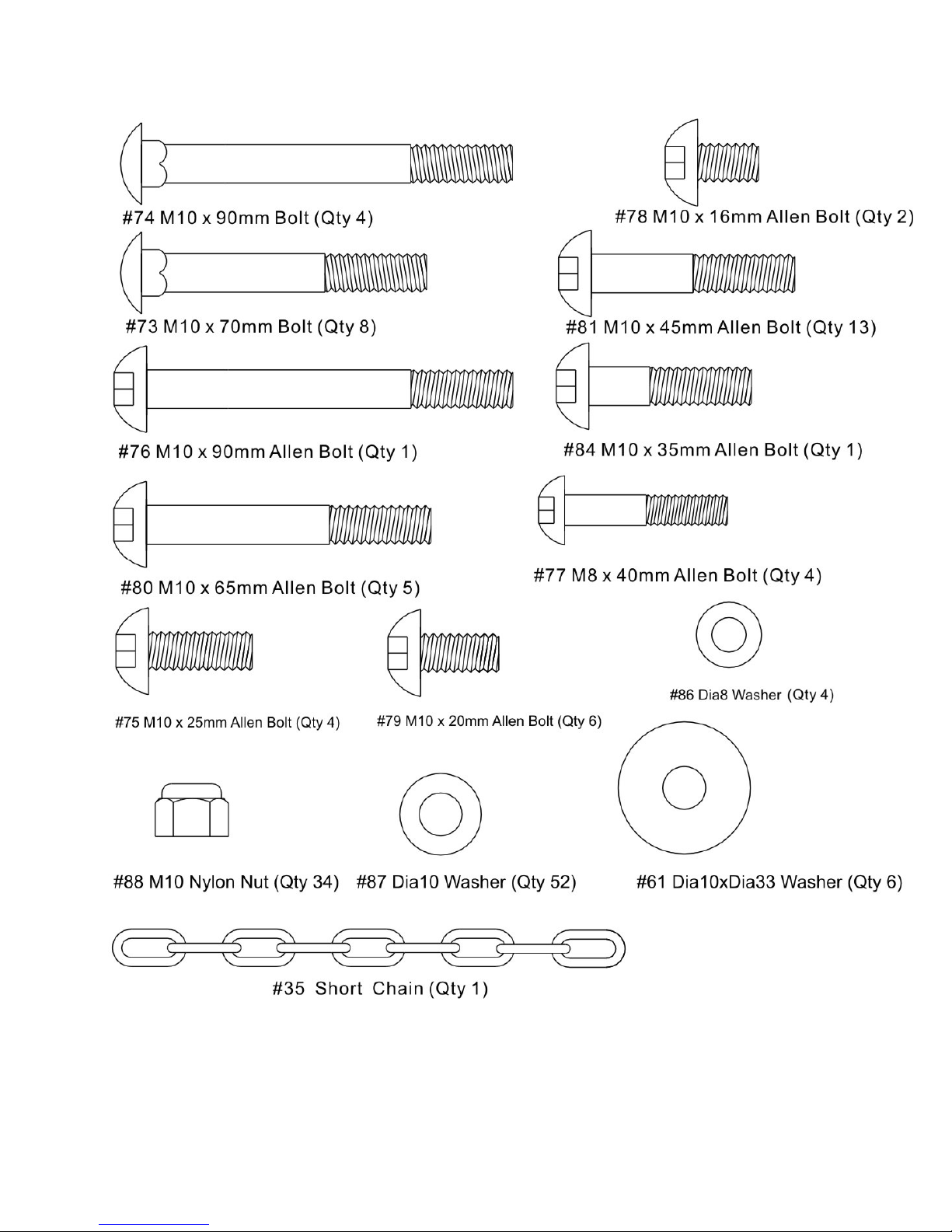
HARDWARE PACK
- 4 -
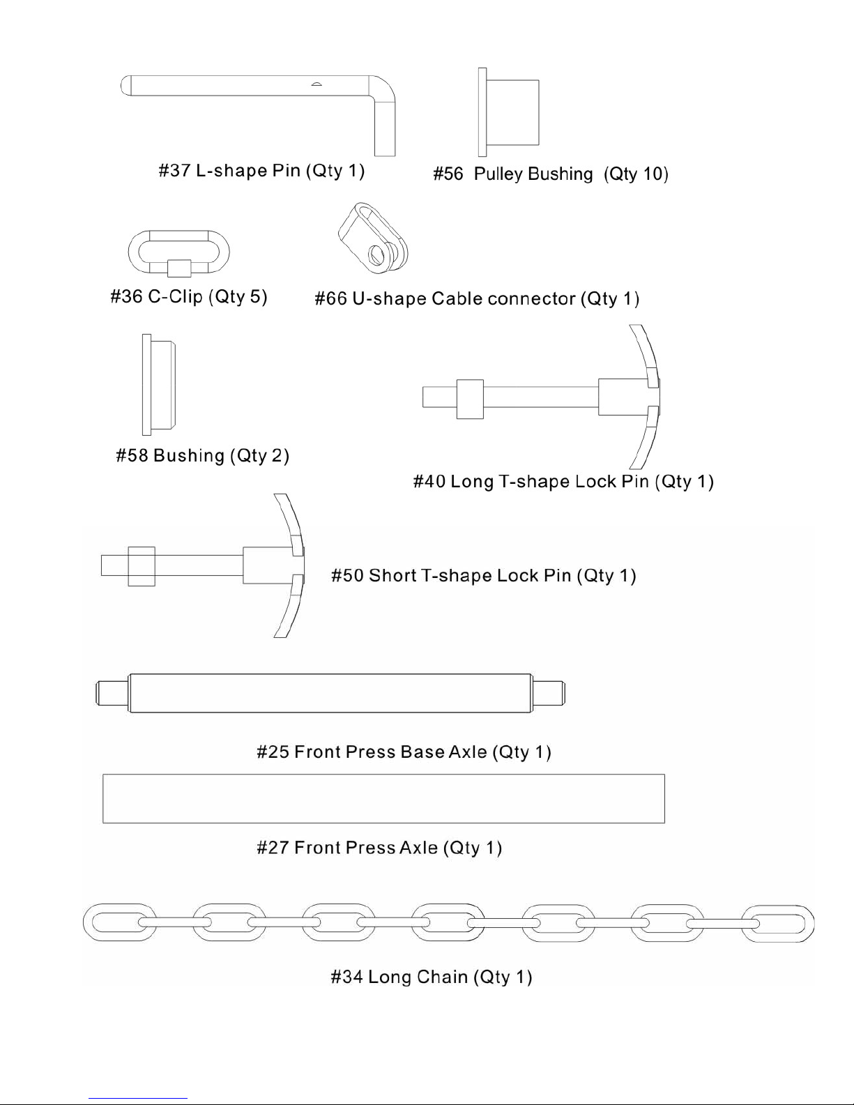
HARDWARE PACK
- 5 -
ASSEMBLY INSTRUCTION
Tools Required Assembling the Machine: Two Adjustable Wrenches and Allen Wrenches
NOTE: It is strongly recommended this machine be assembled by two or more people
to avoid possible injury.
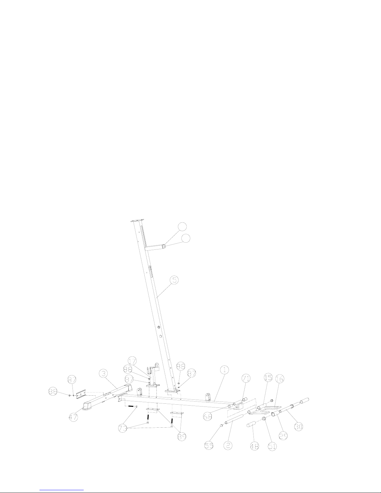
STEP 1 (See Diagram 1)
A.) Attach the Base Frame (#1) to the Rear Base Frame (#3). Secure them with two M10 x
70mm Carriage Bolts (#73), two ∅ 10mm Washers (#87), and two M10 Nylon Nuts (#88).
B.) Attach the Foot Plate (#15) to the Base Frame (#1). Align the holes of the foot plate with
the hole in the Base Frame. Insert the Foot Plate Axle (#2) through the holes. Place Flat
End Cap (#55) in each end of foot plate (#15).
C.) Attach one bar protector (#68) to each side of the bar protector joint on Base Frame (#1)
D.) Attach the Vertical Frame (#5) to the Base Frame (#1). Secure it with two M10 x 70mm
Carriage Bolts (#73), ∅ 10mm Washers (#87), and M10 Nylon Nuts (#88). DO NOT tighten
the Nuts and Bolts yet.
E.) Attach Butterfly Pulley Bracket (#17) to the Base Frame (#1). Secure it with two M10 x
70mm Carriage Bolts (#73), ∅10mm Washers (#87), and M10 Nylon Nuts (#88).
F.) Slide Shiver Bar Frame (#29), Sleeve (#51) and Handle Grip (#48) onto Shiver Bar (#30)
DIAGRAM 1
65
83
- 6 -

STEP 2 (See Diagram 2)
A.) Place two ∅ 60x25mm Rubber Bumpers (#60) on the Rear Base Frame (#3). Align the
holes and insert Two Guide Rods (#18) through the holes into the Rear Base Frame.
Secure each Guide Rod with one M10 x 25mm Allen Bolt (#75) and ∅ 10mm Washer (#87)
from the bottom of Rear Base Frame.
B.) Slide 14 Weight Plates (#46) onto the Guide Rods. Make sure all Plates are facing the
same direction. Insert the Selector Rod (#38) through the center hole on the Weight Plates.
Slide the Weight Selector Stem (#45) onto the Guide Rods.
C.) Use the L-shape Pin (#37) to select desired number of Weight Plates to Exercise. NOTE:
Each Plate weights 10 lbs. Please refer to the Weight Resistance Chart on page 24.
- 7 -
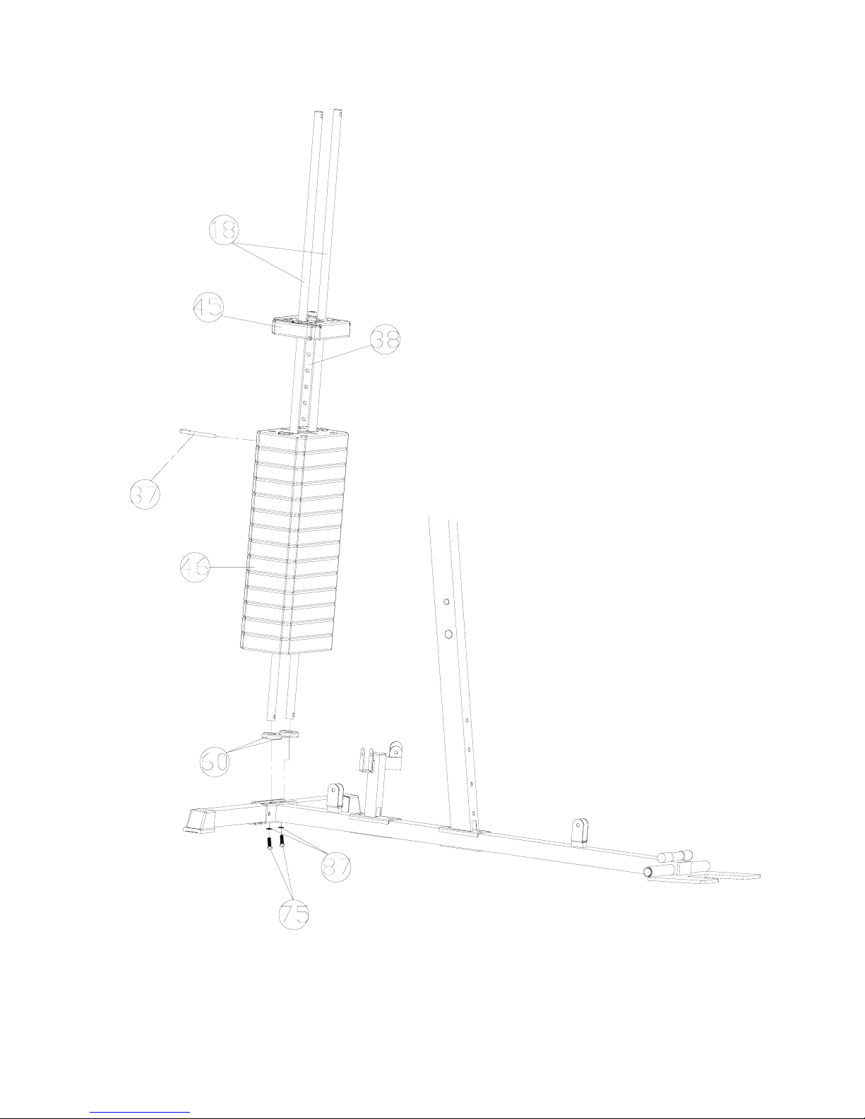
DIAGRAM 2
- 8 -
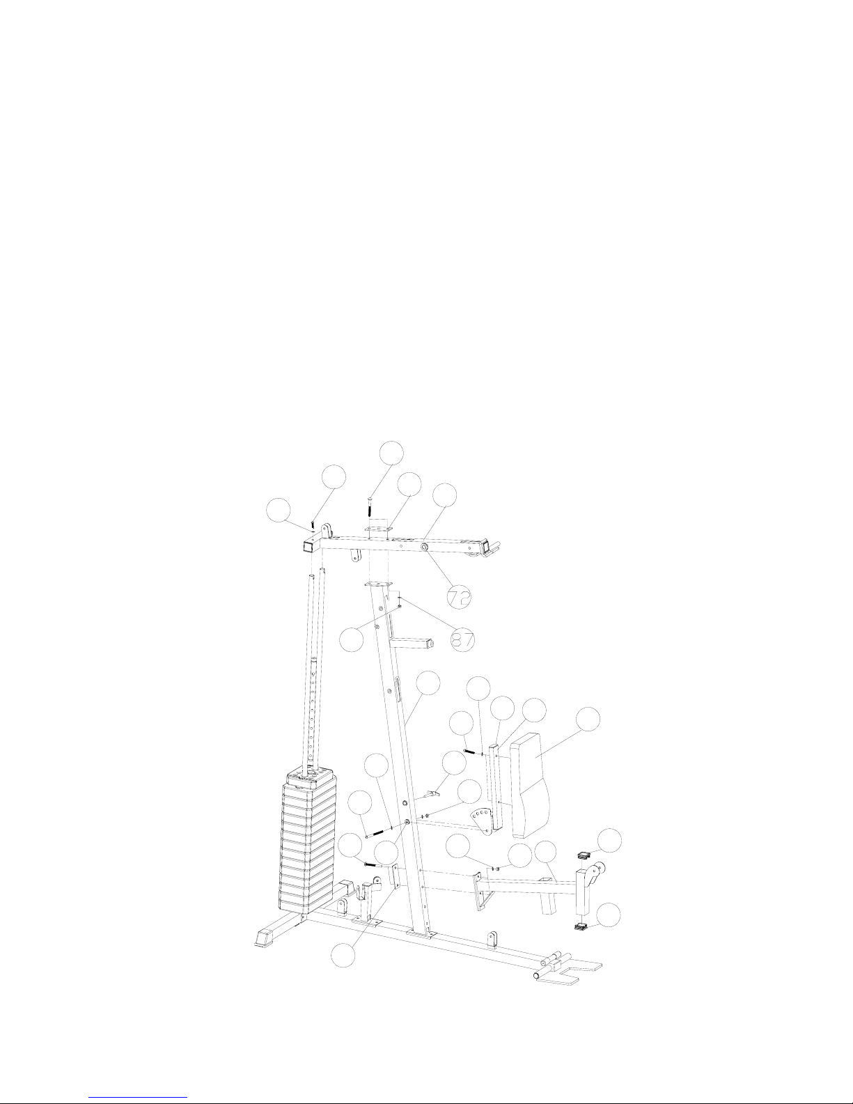
STEP 3 (See Diagram 3)
A.) Attach the Upper Frame (#4) onto the two Guide Rods (#18). Secure each Guide Rod to
the Upper Frame with on M10 x 25mm Allen Bolt (#75) and ∅ 10mm Washer (#87). DO
NOT tighten the Nuts and Bolts yet.
B.) Place the Upper Frame (#4) onto the top of the Vertical Frame (#5). Secure it with one
140x50mm Bracket (#89), two M10 x 70mm Carriage Bolts (#73), two ∅ 10mm
Washers (#87), and two M10 Nylon Nuts (#88).
C.) Securely tighten all Nuts and Bolts previously installed.
D.) Attach the Backrest Pad (#22) to the Backrest Support Frame (#12). Secure it with two
M8 x 40mm Allen Bolts (#77) and ∅8mm Washers (#86).
E.) Attach the Backrest Support Frame (#12) to the Vertical Frame (#5). Secure it with one
M10 x 90mm Allen Bolt (#76), two ∅10mm Washers (#87), and one M10 Nylon Nut
(#88).
F.) Thread the Long T-shape Lock Pin (#40) into the hole on the Vertical Frame (#5). Insert
the Pin into selected hole on the Backrest Support Frame to obtain the desired Backrest
position.
G.) Attach the Seat Support Frame (#6) to the Vertical Frame (#5). Secure it with two M10
x 90mm Carriage Bolts (#74), ∅10mm Washers (#87), and M10 Nylon Nuts (#88).
DIAGRAM 3
87
75
88
74
76
87
58
73
89
4
5
77
86
52
12
22
40
88
87
88
6
53
53
26
- 9 -
 Loading...