

Page 1

www.hypercable.fr - www.e-rake.us.com
1
SeaRake-LandRake
HYC-4009-30
300MHz 2x2 MIMO HT‐OFDM Radio
User Manual
Includes install, configuration and trouble
shooting information for the broadband
wireless access outdoor radio.
Version 1.0.4
Janv.2017
Page 2
www.hypercable.fr - www.e-rake.us.com
2
Recommandations à suivre impérativement
ATTENTION NE PAS METTRE SOUS TENSION SANS QUE L’EQUIPEMENT NE SOIT RACCORDE A UNE
ANTENNE VERIRIEE OU A UNE CHARGE FICTIVE DE 0.5 à 5 WATTS 50 OHMS SELON LE TYPE DE
MODEM.
ATTENTION A LA POLARITE DU 48 VDC NE PAS UTILISER DE POE AUTRE QUE CELUI FOURNI.
Attention, vérifiez en vous connectant aux antennes préinstallées, avec l'aide d'un analyseur de
spectre à mémoire que le canal radio que vous allez choisir dans la bande utilisée (330-370, 445-505
MHz , 4.4-5.0 GHz, 4.8-6.2 GHz) n'est pas occupé par une porteuse d'un niveau supérieur à -70 dBm
(par exemple -60 dBm est un niveau supérieur à -70 dBm) dans tous les cas choisir la zone de votre
canal ou les niveaux parasites mesurés sont les plus faibles.
Manuel du Montage de l'antenne et du modem radio :
Attention, le modem radio ayant changé le montage du modem est légèrement différent le
support du modem est devenu aussi un capot protecteur.
Impératifs techniques de pose ICI
Montage antenne ICI
Montage cablage réglages Modems ICI
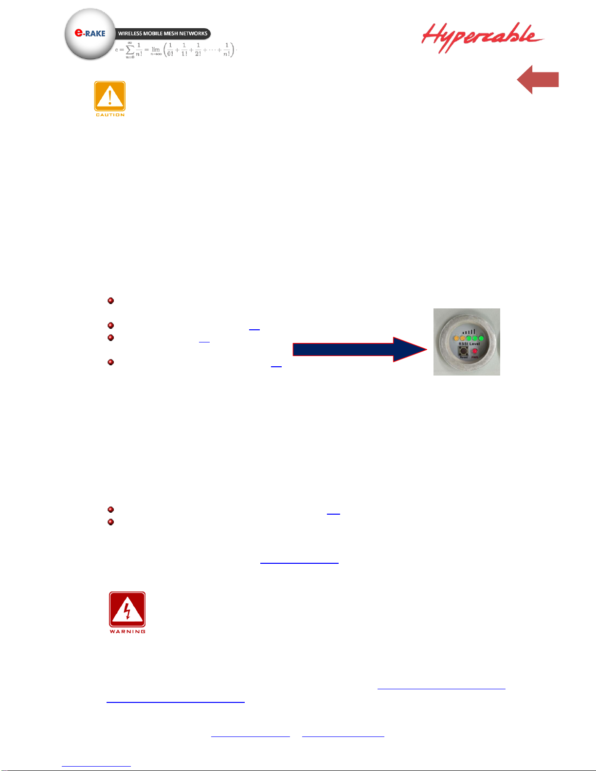
o Attention certains modèles ont pour le pointage et a la place des écouteurs un
Barled indiquant sur la CPE le niveau auquel est reçu le CPE par la station de base
distante, si le pointage est fait par une seule personne qui doit se déplacer d'un point
a un autre il faudra inverser les fonctions base station et CPE lors du pointage afin de
bénéficier du visuel du barled sans avoir a se déplacer du côté opposé. Si le pointage
est fait par deux personnes en liaison radio la personne coté "base sation"
demandera a la personne coté CPE quel est l'affichage obtenu selon le pointage
azimutal en cours.
o Attention de ne pas pointer sur un lobe secondaire de l'antenne.
Notice de montage des modems sur les antennes ICI
Vérifiez le contenu des cartons associés aux Modems et ne pas jeter les cartons sans les
ouvrir entièrement. Conserver les cartons emballages pour les retours sous garantie, les CD
et manuels sont dans chaque Modem radio en cas de doute téléphoner au 06 82 82 38 73
ou ayez recours a un spécialiste installateur certifié pour la pose et configuration des radio
Hypercable.
ATTENTION selon le découplage des antennes et la largeur du canal en version
4x4 le canal CH1 2x2 doit être éloigné du canal Ch2 2x2 de 200 Mhz à 400 Mhz par
exemple CH1 sur 5700 MHz et Ch2 sur 5300 MHz pour des antennes omnidirectionnelles
découplées dans le plan vertical afin d’éviter interférences et désensibilisation. En cas
d’impossibilité des filtres de bande doivent être prévus. (Voir Montage des antennes
installations recommandations)
Nouveau Barled de pointage
Page 3
www.hypercable.fr - www.e-rake.us.com
3
Copyright
Copyright © 2015 all rights reserved. No part of this publication may be reproduced,
adapted, stored in a retrieval system, translated into any language, or transmitted in any
form or by any means without the written permission of the supplier.
About This Manual
This manual includes install, configuration and trouble shooting for the 300 MHz 4x4 MIMO
HT-OFDM MESH Radio. It can help you in avoiding the unforeseen problems and use the
outdoor radio correctly.
Technical Support
If you have difficulty resolving the problem while installing or using the wireless backhaul,
Please contact the supplier for support.
Conventions
This publication uses the following conventions to convey instructions and information:
This symbol means reader take note. Notes contain helpful suggestions or references to
materials not contained in this manual.
This symbol means reader be careful. In this situation, you might do something that could
result in equipment damage or loss of data.
This warning symbol means danger. You are in a situation that could cause bodily injury.
Before you work on any equipment, be aware of the hazards involved with electrical
circuitry and be familiar with standard practices for preventing accidents.
Page 4

www.hypercable.fr - www.e-rake.us.com
4
Table of Contents
CONVENTIONS ...............................................................................................................................3
CHAPTER 1 INTRODUCTION ........................................................................................................5
1-1 FEATURES AND BENEFITS ............................................................................................................... 5
CHAPTER 2 HARDWARE INSTALLATION ...................................................................................6
2-1 PRODUCT KIT ................................................................................................................................. 8
2-2 SYSTEM REQUIREMENTS ................................................................................................................ 8
2-3 MECHANICAL DESCRIPTION ........................................................................................................... 9
ANTENNA LOCATION DEFINITION VERSION 4X4: .................................................................. 10
ANTENNA LOCATION DEFINITION VERSION 2X2: ................................................................... 11
2-4 HARDWARE INSTALLATION........................................................................................................... 13
2-5 LED INDICATORS ......................................................................................................................... 14
CHAPTER 3 CONFIGURATION .................................................................................................. 15
3-1 START-UP AND LOG IN .................................................................................................................. 15
SYSTEM / BASIC SETUP ............................................................................................................. 23
3-2 MESH PROTOCOL CONFIGURATION .............................................................................................. 25
3-3 WIRELESS SETUP ......................................................................................................................... 27
3-4 MANAGEMENT ............................................................................................................................. 32
Page 5
www.hypercable.fr - www.e-rake.us.com
5
Chapter 1 Introduction
1-1 Features and Benefits
Effective spectrum utility / variable capacities with 9 channel BWs
This radio has 8 channel bandwidths (2.5/3/3.5/4/5/6/7/8/10 MHz) for optional, which is
adjustable via software. This function provides flexibilities of channel plan in crowded urban
environment and variable capacities for different applications.
MIMO HT‐OFDM technology provides amazing spectral efficiency
Up to 5.2 bits/s/Hz amazing spectral efficiency for all channel BW provided by the MIMO
HT‐OFDM technology. Work with the variable channel BW options, these two combination
features provides great benefits for both crowded urban area and rural area with less
interference.
Proprietary Security
This radio uses proprietary protocol, which means other standard wifi products can’t connect
to this radio. It also provides WPA‐PSK (TKIP) / WPA2‐PSK (AES128), access control by
allow/deny MAC address list to build the highest security mechanism to prevent the
malicious attacking from the internet.
FEATURES
o Provides the easy installation for outdoor Mobile Mesh or PTP/PTMP applications
with high performance.
o ±2 ppm Frequency Stability for Mobility & NLOS
Transmit Power Control:
With MIMO High Throughput OFDM (HT‐OFDM) technology, this radio is a high capacity
300MHz UHF band radio for Mobile Mesh or PTP/PTMP wireless deployment. It utilizes
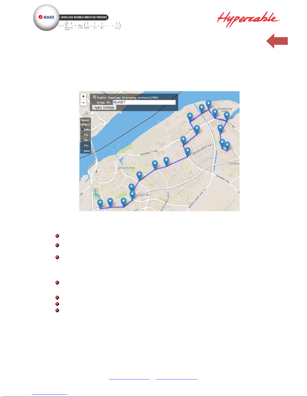
coordinate and internet map database to show the environment and status of the link.
Customers can easily figure out the linking situation of the deployed radios.
There are 8 channel BW (2.5/3/3.5/4/5/6/7/8/10 MHz) options can be selected easily by
software. UHF band with narrow channel BW provides the flexibility of deployment
channel plan in high density city area and NLOS mobility applications.
This MIMO HT‐OFDM mobile mesh radio has powerful security mechanism such as:
WPA‐PSK (TKIP) / WPA2‐PSK (AES128), access control by allow/deny MAC address list,
plus the proprietary protocol. This outdoor radio also supports excellent MTBF
performance by IP‐68 dust & water resistant ratings, integrated surge protection circuit in
both radio and POE unit. All these functions make this outdoor radio much more secure
and reliable.
Page 6
www.hypercable.fr - www.e-rake.us.com
6
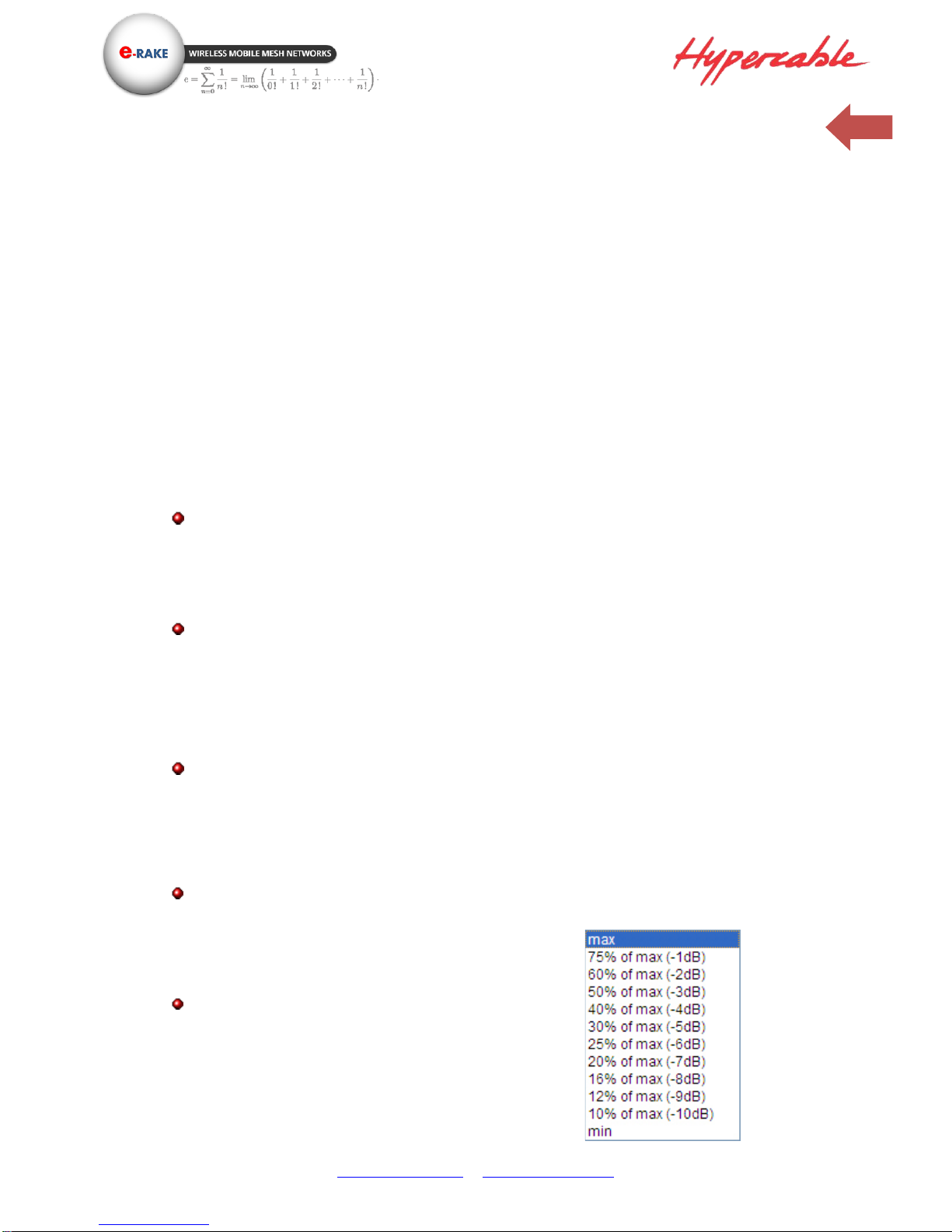
Supports settable transmit power levels to adjust coverage cell size, ranging from max.(100%) to 10%
of max., the adjustment step is 1dB.
o 8Channel BW (2.5 /3/ 3.5/4/ 5 / 6 / 7/10MHz)
o Multi‐hops repeating & Built‐in NMS with GPS Coordinates and Internet map.
o 5.2 bits/s/Hz amazing spectral efficiency
o High Efficiency in Multi‐hops Repeating
Low Throughput dropped @ 40MHz Ch BW (≧170 Mbps @ 20 hops)
Short Latency increased @ 40MHz Ch BW (≦35 ms @ 20 hops)
Network Architecture:
o P‐T‐P: 1+0/2+0 / 1+1
o P‐T‐MP Ring (Redundant)
o Mobile MESH
Fast Seamless Roaming
High Speed up to 180km/hr
IEC61000‐4‐5 Surge Protection
IP‐68 Water & Dust Resistant
Chapter 2 Hardware Installation
This chapter describes initial setup of the 300MHz UHF band 2x2 MIMO HT-OFDM MESH Radio
Page 7
www.hypercable.fr - www.e-rake.us.com
7
Warnings
In order to comply with international radio frequency (RF) exposure limits, dish
antennas should be placed at a minimum of 8.7 inches (22 cm) from the bodies of all
persons. Other antennas should be laced a minimum of 7.9 inches (20 cm) from the
bodies of all persons.
Do not work on the system or connect or disconnect cables during periods of lightning
activity.
This equipment must be grounded. Never defeat the ground conductor or operate the
equipment in the absence of a suitably installed ground conductor. Contact the
appropriate electrical inspection authority or an electrician if you are uncertain that
suitable grounding is available.
Ultimate disposal of this product should be handled according to all national laws and
regulations.
Do not locate the antenna near overhead power lines or other electric light or power
circuits, or where it can come into contact with such circuits. When installing the
antenna, take extreme care not to come into contact with such circuits, as they may
cause serious injury or death. For proper installation and grounding of the antenna,
please refer to national and local codes (e.g. U.S.:NFPA 70, National Electrical Code,
Article 810, in Canada: Canadian Electrical Code, Section 54) and CE regulations.
Only trained and qualified personnel should be allowed to install, replace, or service this
equipment.
To meet regulatory restrictions, the radio and the external antenna must be
professionally installed. The network administrator or other IT professional responsible
for installing and configuring the unit is a suitable professional installer. Following
installation, access to the unit should be password protected by the network
administrator to maintain regulatory compliance.
Page 8
www.hypercable.fr - www.e-rake.us.com
8
The 300 MHz UHF Band 2x2 MIMO HT-OFDM MESH Radio and POE injector can be
damaged by incorrect power application. Read and carefully follow the installation
instructions before connecing the system to its power source.
Follow the guidelines in this chapter to ensure correct operation and safe use of the
300Mhz 2x2 MIMO HT-OFDM MESH Radio.
2-1 Product Kit
Before installation, make sure that you the following items:
300 MHz 2x2 MIMO HT-OFDM MESH Radio…...........…...….......…..…….....…..…..…..x 1
Power over Ethernet……………………………………………………………..…………….….……x 1
Power Adapter………………………………………………………………….………….………......…x 1
Power Cord…………………………………………….….……………………………………………...…x 1
Water-proof connector for SFTP cable…………………………………………….……………x 1
Mounting kit .....…………………………….……….…………………………………………….........x 1
Product CD………………………………………………………….…………………………….…….…….x 1
Quick Installation Guide…………………………………….….………………………………….....x 1
NOTE: If any of the above items are missing or damaged, please contact your local dealer for support.
2-2 System Requirements
Before installing the 300 MHz long distance wireless backhaul, please make sure that these
requirements have been met:
A 10/100/1000 Mbps Local Area Network device such as a hub or switch. (optional)
Category 5 UTP or STP networking cable. (From the PC to POE)
Category 5 SSTP or SFTP networking cable. (From the radio to POE)
A Web browser for configuration: Google Chrome or Microsoft IE 9.0 or later.
Installing TCP/IP protocol to the computer.
Page 9
www.hypercable.fr - www.e-rake.us.com
9
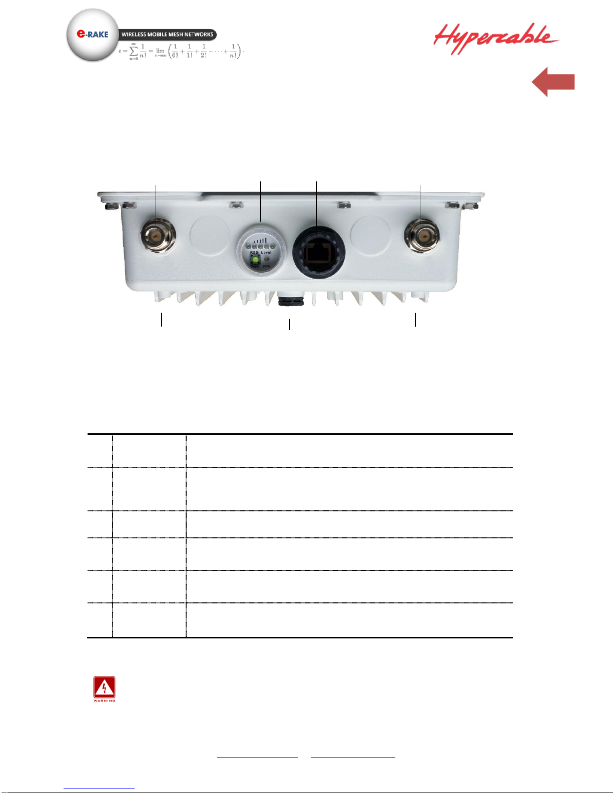
2-3 Mechanical Description
Please refer to the following table for the meaning of each feature.
ODU: (External antenna)
Bottom Side
Outdoor Multi-function Radio Figure
Note:
1. RF1-Primary port connect to V. polarization of the MIMO antenna. Or -45° slant or RHCP
2. RF1-Secondary port connect to H. Polarization of the MIMO antenna. Or +45° slant or LHCP
Note: screw the cap back well after you use the reset button or beeper.
This equipment must be grounded. Never defeat the ground conductor or operate the
equipment in the absence of a suitably installed ground conductor. Contact the
appropriate electrical inspection authority or an electrician if you are uncertain that
suitable grounding is available.
1
RJ-45 Port
Use the SFTP cat.5 cable with weatherproof connector to connect to the “To ODU” side of
the POE injector.
2
N- Jack Antenna
Connector
Here you can attach the N-type external antenna to the 300 MHz 4x4 MIMO HT-OFDM
MESH Radio. In order to improve the RF signal radiation of your antenna, proper antenna
installation is necessary.
3
Grounding stud
Connect to the ground conductor with the ground wire.
4
Reset button
Revolve the plastic cap, you will see the reset button. Press it and hold for 5~10 seconds,
the radio will back to factory default settings.
5
RSSI LED
Indicator
Indicate the link status info of the Wireless modules, please refer to segment 2-5 for the
LED indicating rules.
6
Membrane Vent
1. Moisture vapor permeable to help aid in condensation and fogging reduction in the
ODU.
2. High airflow allows pressure equalization to prevent stress on enclosure seals
RJ-45 Port
RSSI LED Indicator
& Reset button
RF1- Primary
RF1- Secondary
Grounding stud
Membrane Vent
Grounding stud
Page 10
www.hypercable.fr - www.e-rake.us.com
10
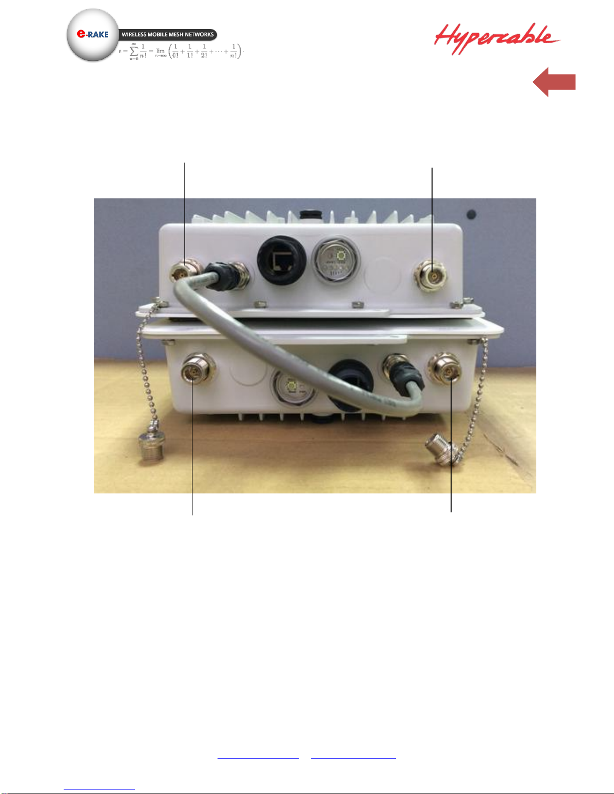
Antenna location definition version 4x4:
※ Note:
1. When you set the RF to 1x1 instead of 2x2 MIMO, only Primary port works.
2. RF1 = Wireless 1 / RF2 = Wireless 2 in the configuration page.
3. With Daisy chain M12 junction cable
RF1- Primary
RF1- Secondary
RF2- Primary
RF2- Secondary
Page 11
www.hypercable.fr - www.e-rake.us.com
11
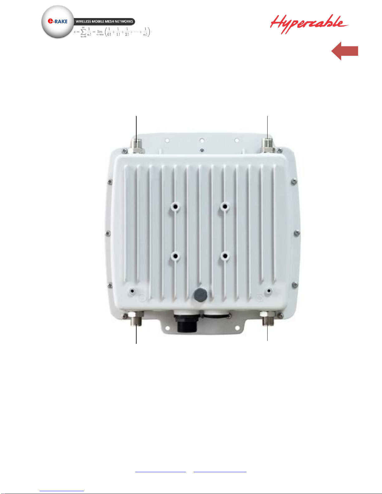
Antenna location definition version 2x2:
※ Note:
1. When you set the RF to 1x1 instead of 2x2 MIMO, only Primary port works.
2. RF1 = Wireless 1 / RF2 = Wireless 2 in the configuration page.
RF1- Secondary
RF1- Primary
GPS Ant
Option WiFi
Page 12
www.hypercable.fr - www.e-rake.us.com
12
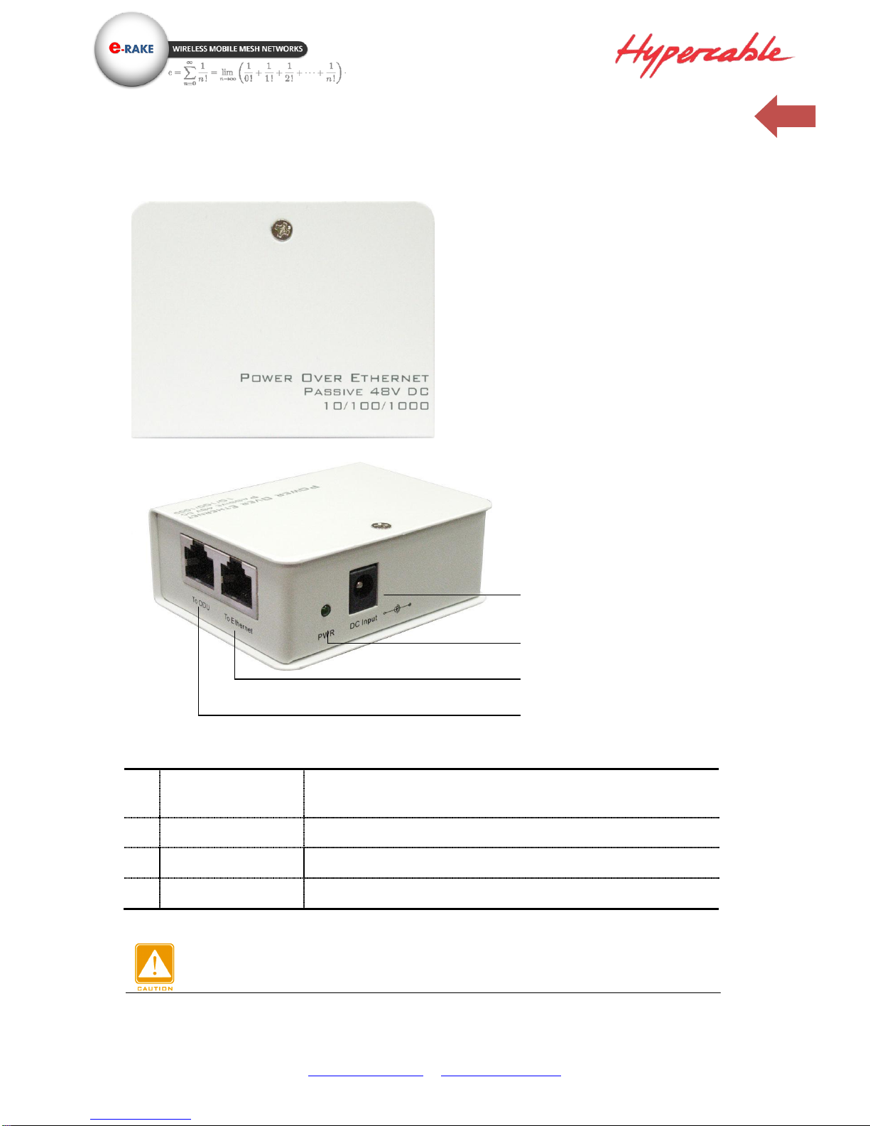
POE – 10 / 100 / 1000 with Passive 48V DC
Power Over Ethernet Injector Figure
Power Over Ethernet Injector is not a waterproof unit, should not be exposed to the
outdoor without any protection.
1
To Ethernet
This RJ-45 port is used to connect to the 10 / 100 / 1000 Base T complied
device such as switch, router or PC.
2
To ODU
This RJ-45 port (10 / 100 / 1000) is used to connect to the ODU. .
3
DC Input
Connect to the Power adaptor for DC input. (Passive 48V DC)
4
LED Indicator
Power LED
To Ethernet
To Radio
DC Input
LED Indicator (Power)
Page 13
www.hypercable.fr - www.e-rake.us.com
13
2-4 Hardware Installation
The 300MHz UHF band 2x2 MIMO HT‐OFDM radio is a radio device, so it is susceptible to common
causes of interference that can reduce throughput and range. Follow these basic guidelines to ensure
the best possible performance:
IF there is any other 300MHz RF device deployed around the outdoor radio, try to set the channel to
the non-overlapping one.
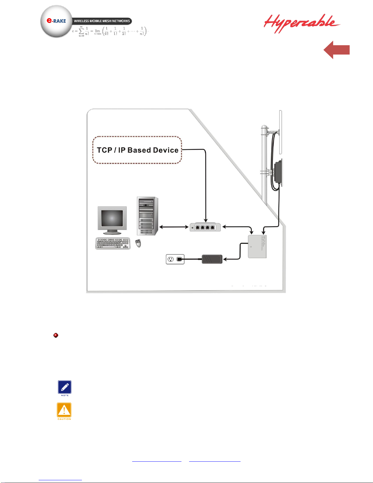
Hardware Installation Figure
Install the bridge at a height sufficient place where structures, trees, or hills do not obstruct radio
signals to and from the unit. A clear line-of-sight path can guarantee the performance of the RF link.
Site Surveys
Clear and flat area provide better RF range and data rate, on the contrary, physical obstructions such
as trees, electric tower, hills or buildings can reduce the performance of RF devices. Do not deploy
your radios in the location where there is any obstacle between the antennas.
Configure and verify the 300 MHz UHF 2x2 MIMO HT-OFDM MESH Radio operations first before you
mount the radio in a remote location.
Power Over Ethernet Injector is not a waterproof unit, should not be exposed to outdoor without
any protection.
Hardware Installation
MIMO Panel
Antenna
Multi-MIMO Mesh
outdoor radio
Power adaptor
POE
AC Outlet
Router / Switch
OUTDOOR
INDOOR
10/100/1000 Mbps
10/100/1000 Mbps
Page 14
www.hypercable.fr - www.e-rake.us.com
14
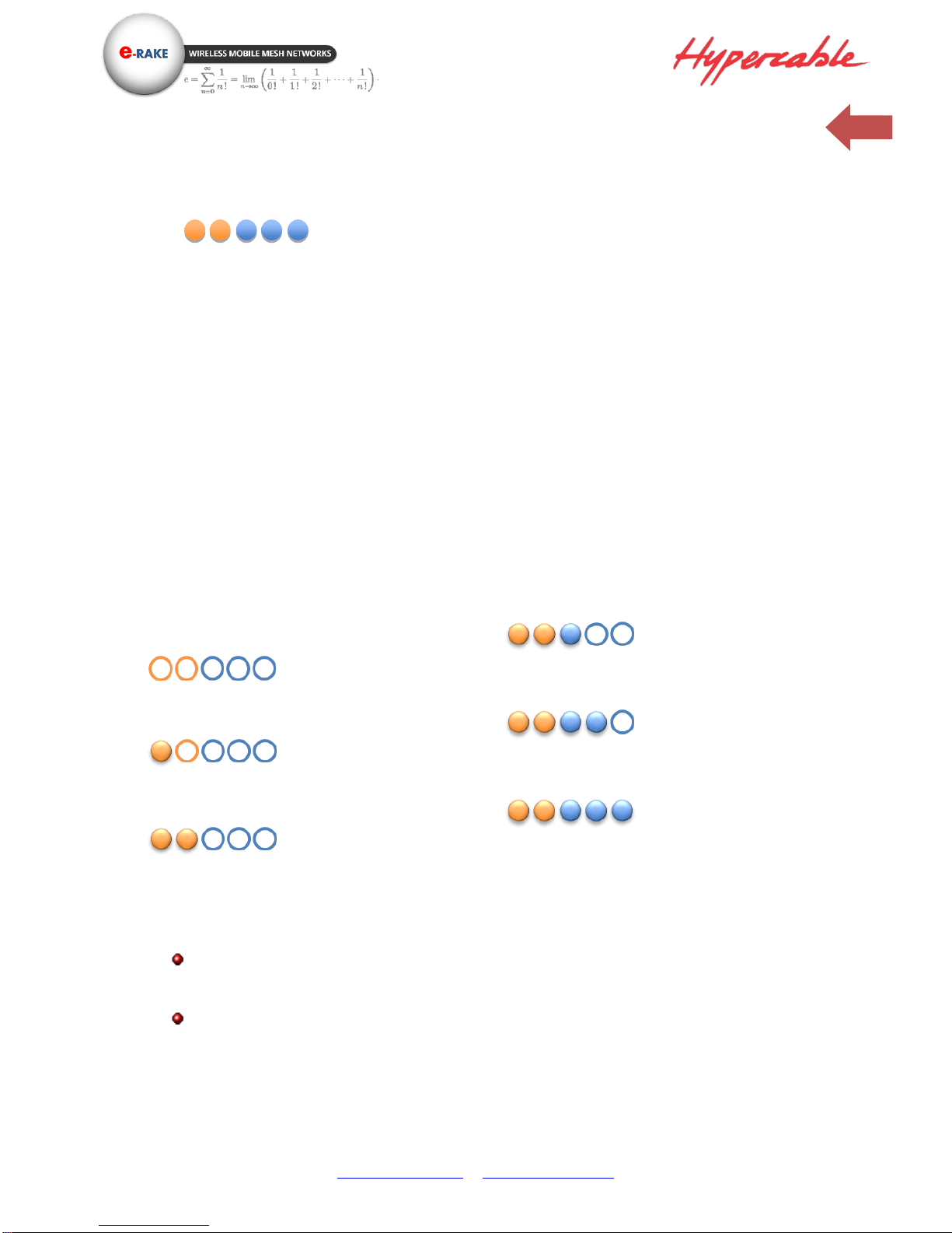
2-5 LED Indicators
BS mode: (PTP / PTMP)
Only LED 1 & 2 will be functional
LED1: On = RF enable;
Off = RF disable
LED2: On = there is CPE associated;
Off = 0 CPE associated.
CPE/ Bridge/Mesh
Disconnected: Scanning mode
LED1 ~ 5 blinking one by one.
Connected: RSSI mode
No LEDs on : RSSI < -85dBm
LED1 on: -81dB ≧ RSSI ≧ -85dBm
LED1~2 on: -76dB ≧ RSSI ≧ -80dBm
LED1~3 on: -71dB ≧ RSSI ≧ -75dBm
LED1~4 on: -66dB ≧ RSSI ≧ -70dBm
LED1~5 on: RSSI ≧ -65dBm
Note 1: when the radio is configured as mesh mode, the RSSI is value is average RSSI which
is calculated from all the connected mesh nodes.
Note 2: LED indicator showed the status of Wireless1.
1 2 3
4
5
Page 15
www.hypercable.fr - www.e-rake.us.com
15
Chapter 3 Configuration
3-1 Start-up and Log in
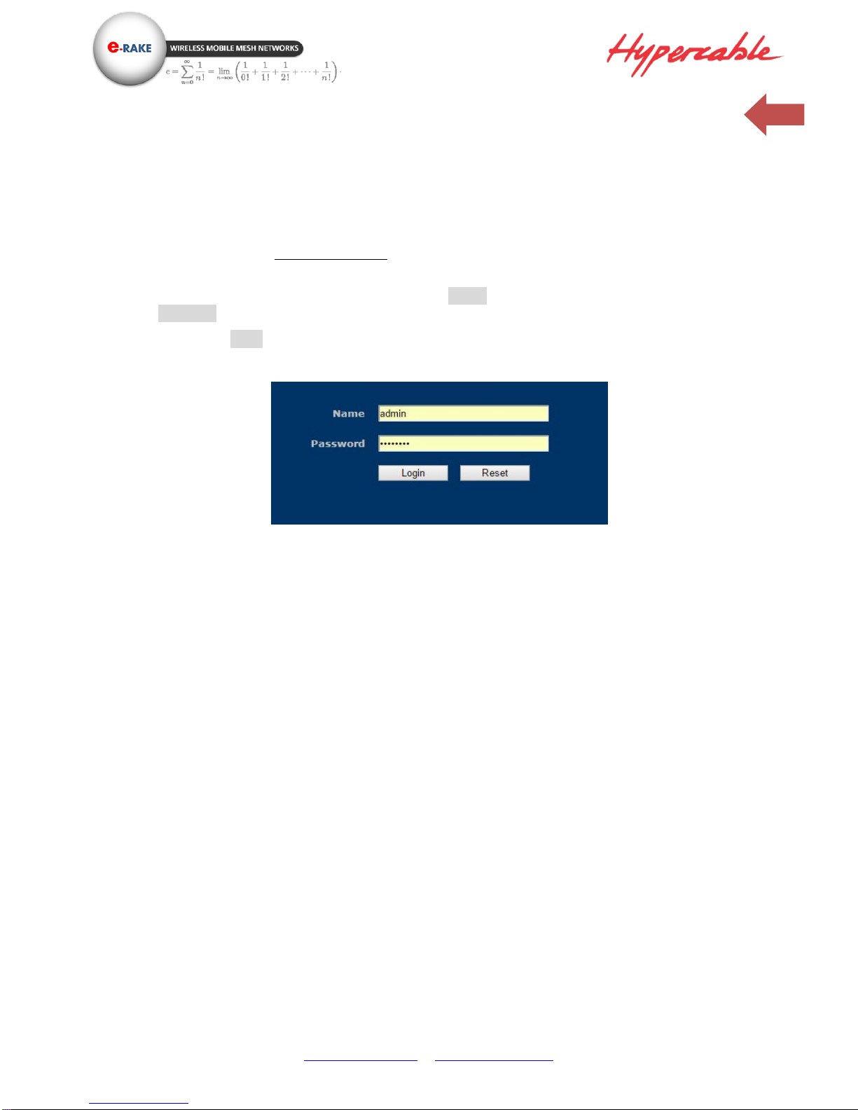
In order to configure the long distance backhaul, use the web browser and please do the following:
1. Type the IP address http://192.168.1.1 of this radio in the Location (for IE) or Address field and
press Enter.
2. Enter the system name (the default setting is “admin”) and password (the default setting is
“password”).
3. Click on the “Login” button.
After you have logged-in the main page, the Information, Status, MAP, System, Mesh, Management
and Logout buttons will be shown in left part. The main menu provides links to the whole sections of
the web configuration interface.
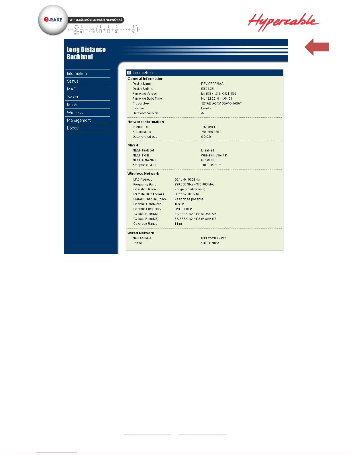
Information
This page shows most of the product information briefly, that includes General Information,
Network Information, MESH, Wireless Network 1, Wireless Network 2 and Wired Network
Page 16
www.hypercable.fr - www.e-rake.us.com
16
Information -1
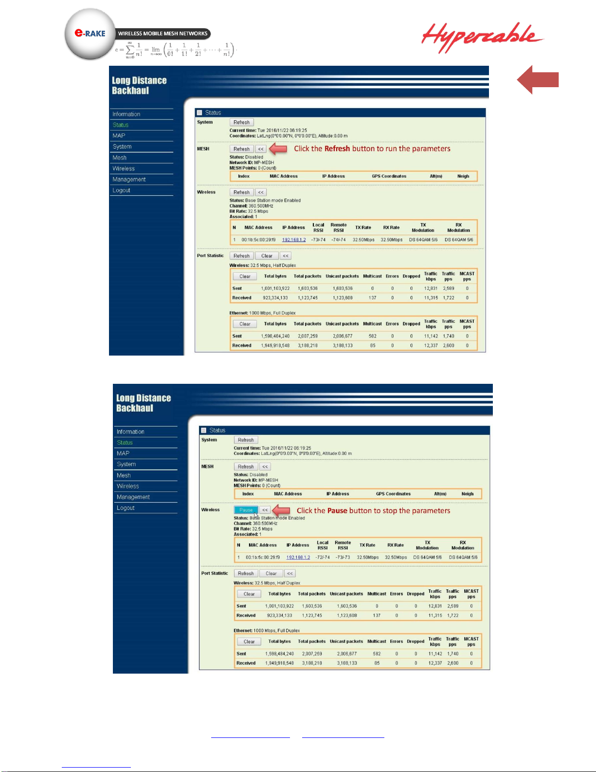
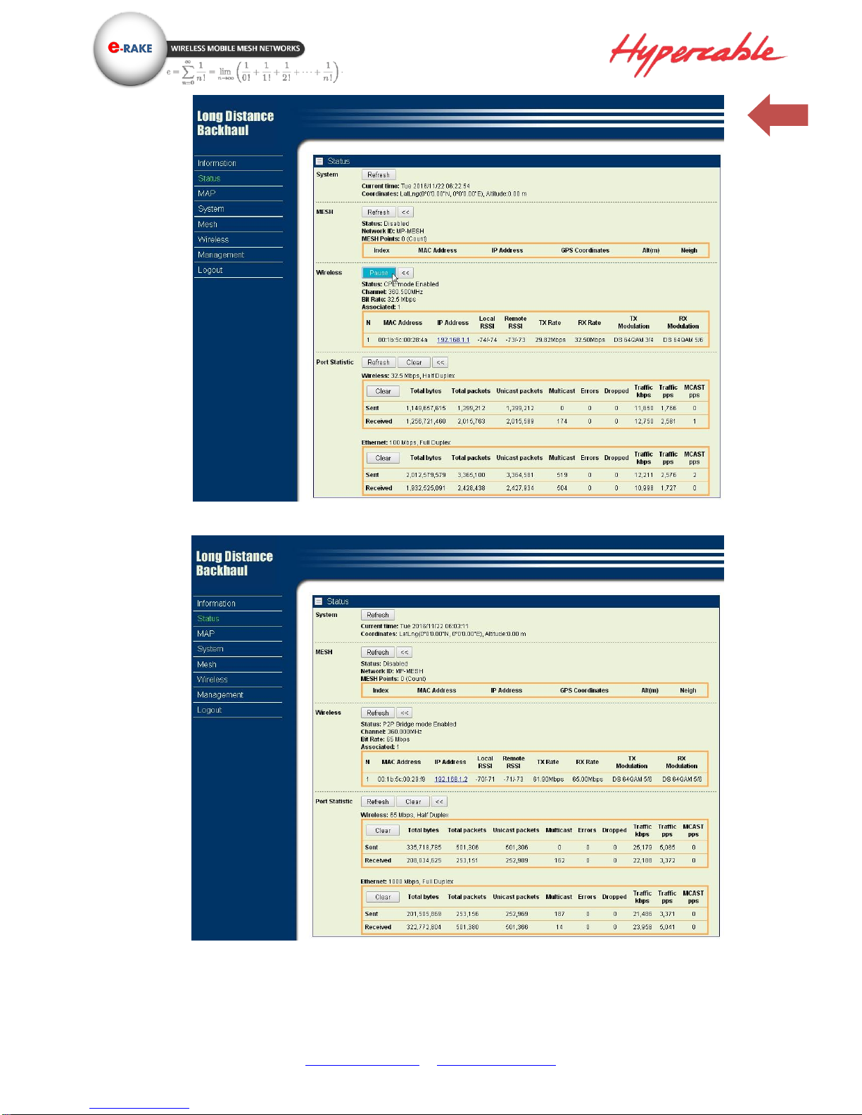
Status
This page shows all the status of the radio in one page, such as System, mesh, wireless and
port statistics.
Page 17
www.hypercable.fr - www.e-rake.us.com
17
Status -1 – (Base station mode)
Status -2 (Base station mode)
Page 18
www.hypercable.fr - www.e-rake.us.com
18
Status ‐CPE mode
Status – PTP Bridge mode
Page 19
www.hypercable.fr - www.e-rake.us.com
19
Map
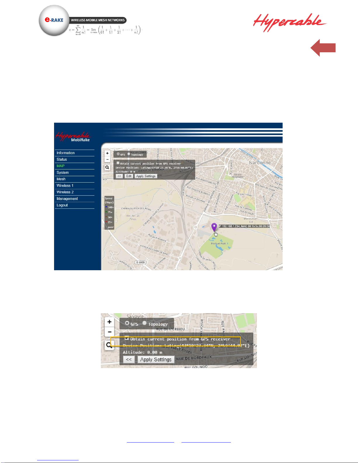
The MAP page shows the location / IP address / MAC address of your radio, GPS coordinates info,
and Topology Status of PTP/PTMP & Mesh Network. It also allows you to drag the radio location
mark to the place wherever you want. And in topology mode, you can also monitor the RF settings
and the link quality among the radios.
There are 3 ways to set the location of the radio.
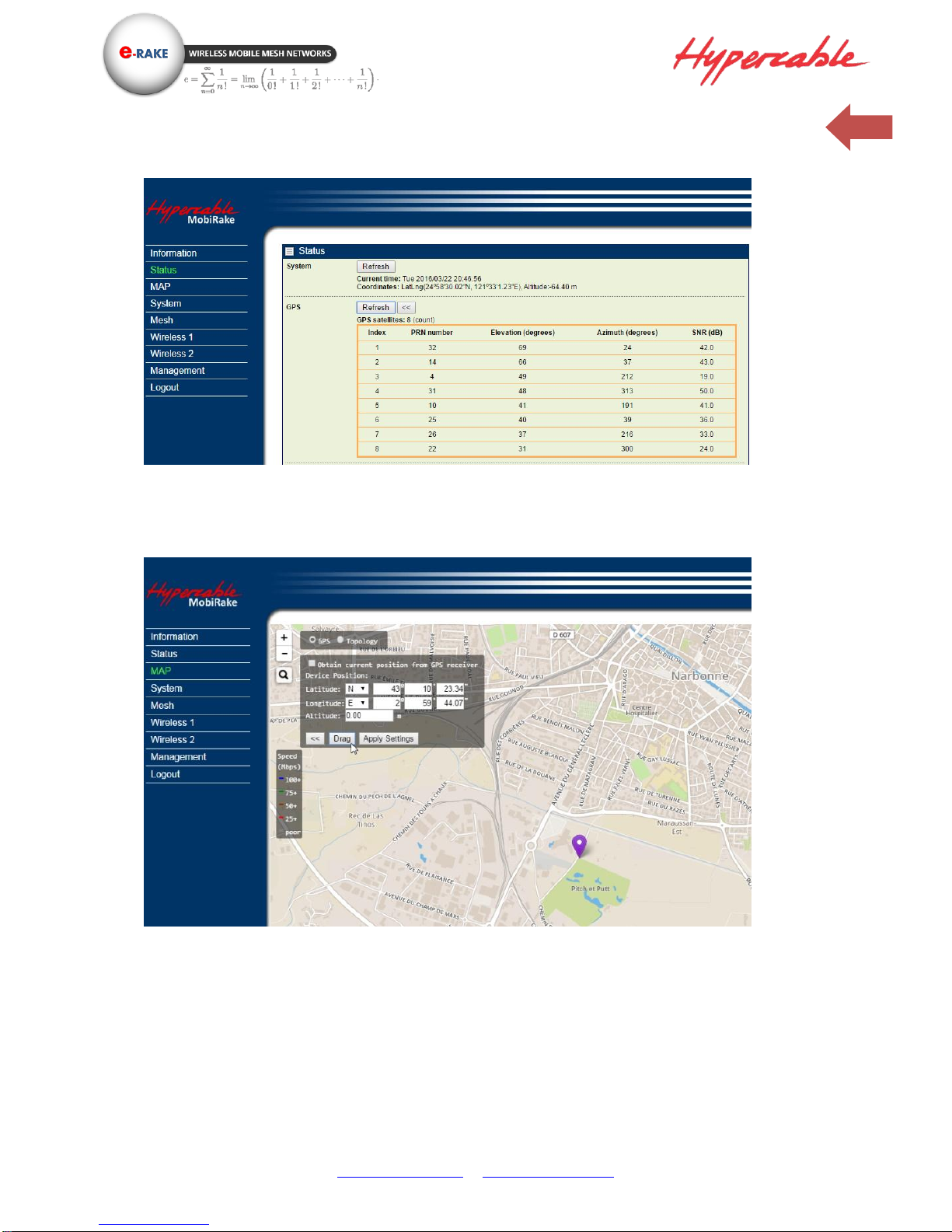
1. You can select “Obtain current position from GPS receiver” with the radio type that integrated GPS
module.
Attach an external GPS active antenna to the GPS port, you can see the received list of the GPS
satellites.
Page 20
www.hypercable.fr - www.e-rake.us.com
20
2. Enter the coordinates manually (this can also be done in System / Basic Setup) or
3. Drag the location mark of the radio to anywhere in the map you want.
Page 21
www.hypercable.fr - www.e-rake.us.com
21
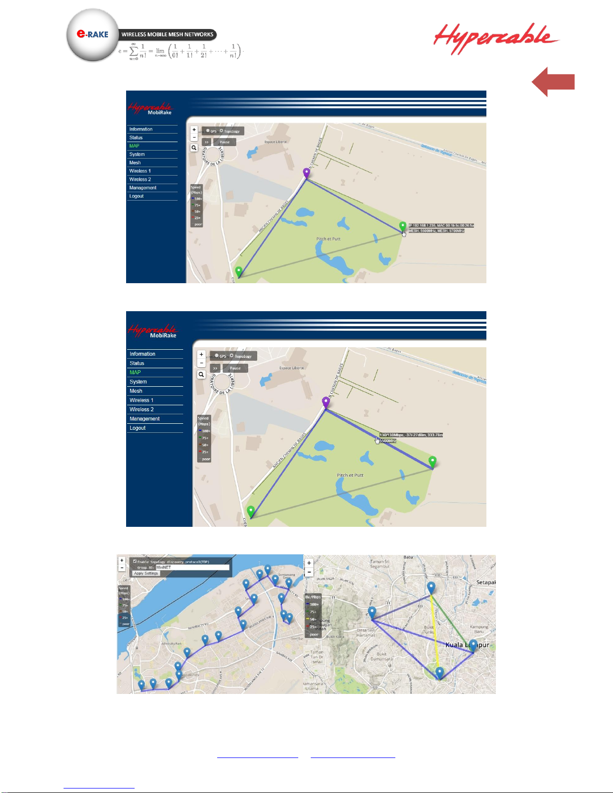
MAP – Topology
Topology Map – Radio info (IP address/ MAC / operating mode & Frequency)
Topology Map – Link status (Data rate / RSSI / Distance / Frequency)
Topology Map – Multi-hops repeating Topology Map – Mesh Network
Page 22
www.hypercable.fr - www.e-rake.us.com
22
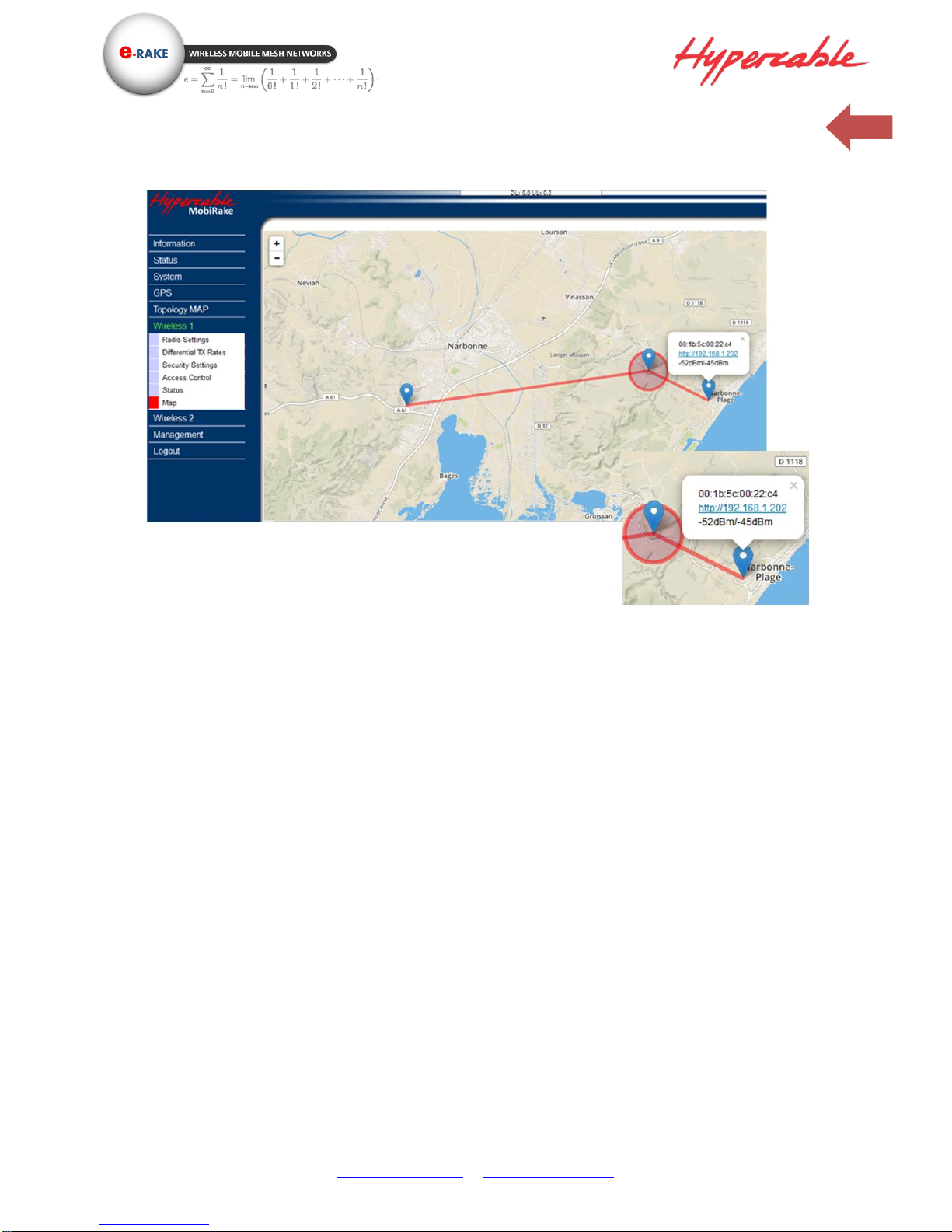
Topology Map – PMPT from a Relay repeater in the Mountain
Page 23
www.hypercable.fr - www.e-rake.us.com
23
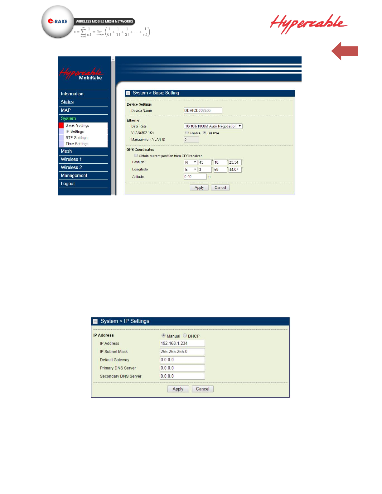
System / Basic Setup
The Device Name is used to give a name to your 300 MHz 4x4 MIMO HT-OFDM MESH Radio. This will
enable you to manage your radio more easily if there are many radios in your network.
Ethernet Data Rate: you can choose the Ethernet data rate of this radio.
VLAN (802.1Q): enable this feature and assign a management Vlan ID to the radio. Those PC without
same Vlan ID will not be allowed to connect this radio and configure it.
GPS Coordinates: Input the Latitude and Longitude info of the 300 MHz 4x4 MIMO HT-OFDM MESH
Radio’s location, and click apply, radio will get the map from internet automatically.
If your radio type support integrated GPS module, you can check the select box “Obtain current
position from GPS receiver”
System / IP Settings
IP Address: Type the IP address you want to set to your 300 MHz 4x4 MIMO HT-OFDM MESH Radio
(Default: 192.168.1.1).
IP Subnet Mask: The Wireless backhaul’s Subnet Mask must be the same as your Ethernet network.
We recommended that you do NOT change the value. (Default: 255.255.255.0).
Page 24
www.hypercable.fr - www.e-rake.us.com
24
Default Gateway: The Wireless backhaul will use this value for default Gateway.
Primary DNS Server: The Wireless backhaul will use this value for primary Domain Name Server.
Secondary DNS Server: The Wireless backhaul will use this value for secondary Domain Name Server.
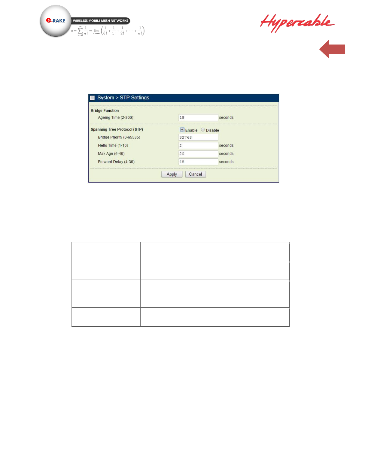
System / STP Settings
Ageing Time: Configure the length of time that a dynamic entry can remain in the bridge table from
the time the entry is created or last updated.
Spanning tree protocol (STP): You may Enable or Disable the Spanning Tree Protocol used in this
radio.
Bridge Priority
Specifies the bridge STP priority
Hello Time
Specifies the interval between the hello BPDUs
Max Age
Specifies the interval that the bridge waits to hear BPDUs
from the spanning tree root
Forward Delay
Specifies a forward delay interval on the bridge
Note: If you complete the settings, please click on “Apply” for changes to take effect.
Page 25
www.hypercable.fr - www.e-rake.us.com
25
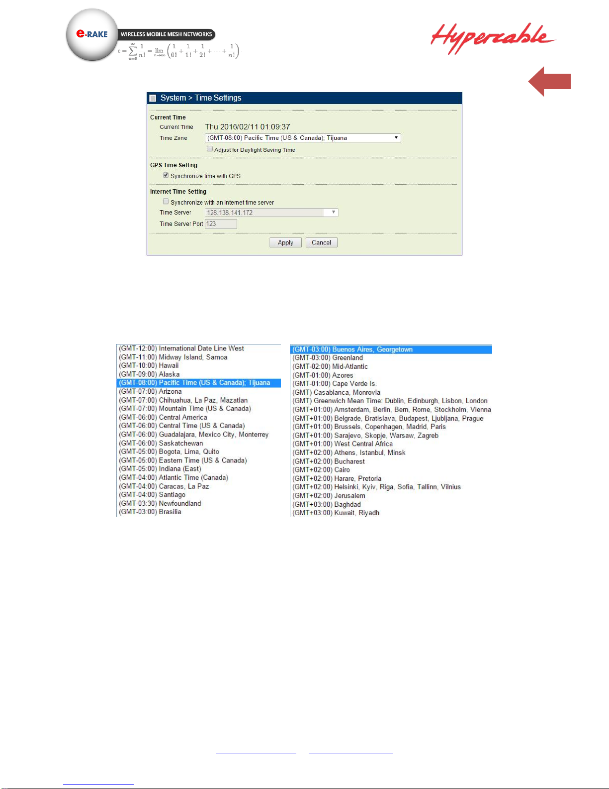
System / Time Setting
Current Time: While you connect this Wireless backhaul to Internet, it could automatically
synchronize the current time with the Time Server that you have set.
Time Zone: You may select the appropriate local time zone for your radio from a list of all available
time zones. Such as below list:
GPS time settings: Sync the time with GPS module.
Time Server: the central time of the Time Server.
Time Server Port: the port of the Time Server.
Time server for a Lan connection to an Orange ADSL router is 192.168.1.1
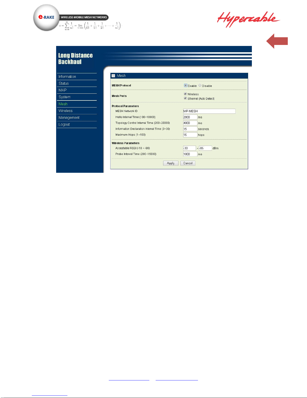
3-2 Mesh Protocol Configuration
Page 26
www.hypercable.fr - www.e-rake.us.com
26
Mesh Protocol: You can Enable or Disable Mesh Routing protocol here.
Mesh Ports: Enable Mesh Protocol per interfaces. When the interfaced been checked, it has to connect to
the other port with same mesh protocol. Otherwise, the connection will be failed. But the Ethernet port with
Auto Detect can auto detect the protocol and get link automatically.
Mesh Network ID: All mesh nodes in the same network must have the same ID.
Hello interval time (1~10s): Time between Hello packets sent by the router on this interface. This value
should be same for all interfaces connected to common network. The default value is 2 seconds.
Topology Control interval Time (1~20s): Topology Control message interval time. Topology control protocols
are designed to exploit node density in the network to extend the network lifetime and provide connectivity.
The following criteria have been identified as the key concepts for designing topology control protocols for
wireless sensor networks.
1. Sensor nodes should be able to self-configure to accommodate changing network dynamics.
2. Selection of redundant nodes should be done based on distributed localized algorithms.
3. Topology control protocols must ensure minimum connectivity in the network, so that the network is
not partitioned.
4. Topology control protocols should take advantage of the high node density in large-scale wireless
sensor networks to reduce the energy dissipated in the network.
Maximum Hops (1~30): Define the max repeating hops in the mesh network.
Acceptable RSSI (-50~-90dBm): This RSSI threshold is an important reference parameter to decide to hold
the link between the Mesh nodes or change to other better optional path.
Probe interval time: Configuring the Time Interval between Probes.
Page 27
www.hypercable.fr - www.e-rake.us.com
27
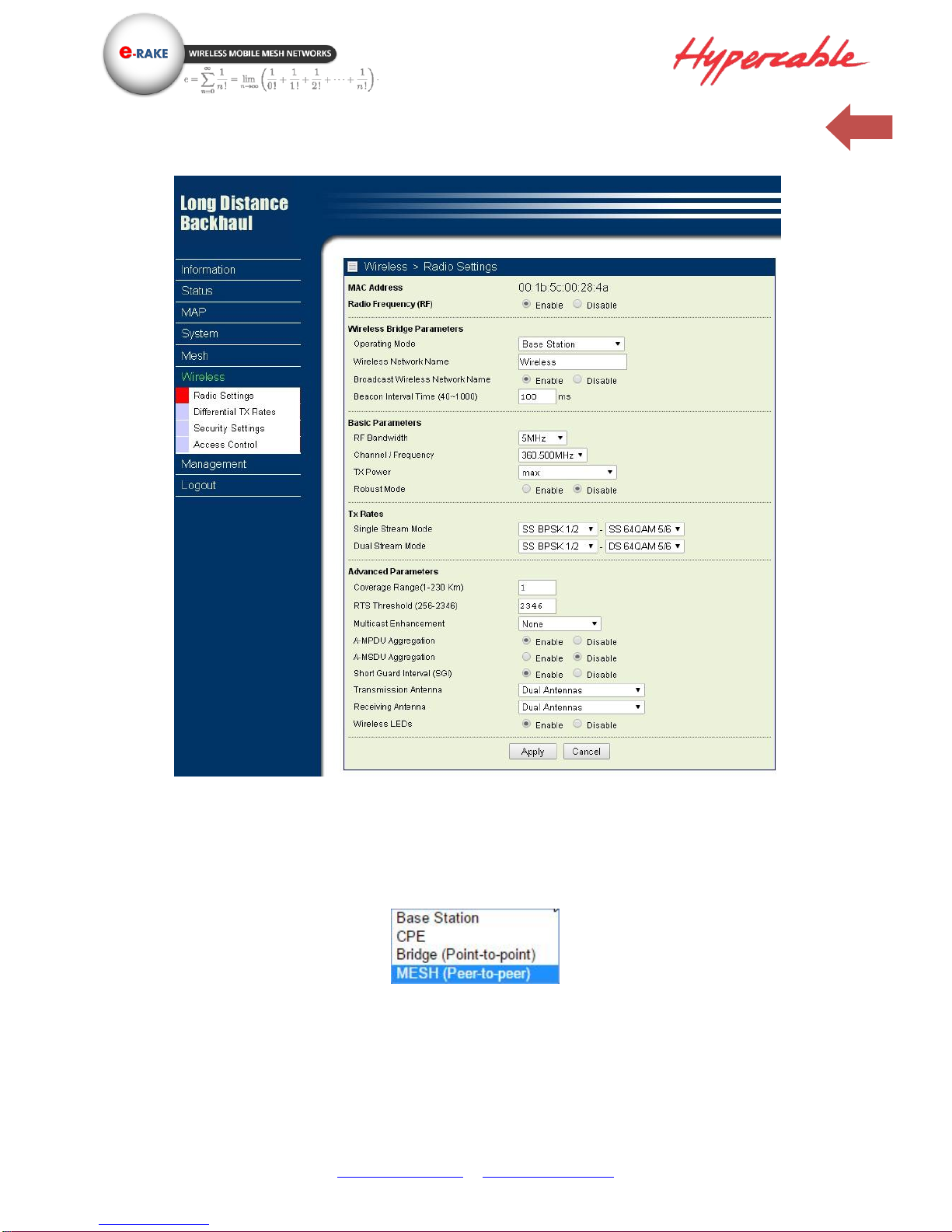
3-3 Wireless Setup
Wireless Setup / Radio
Radio Frequency (RF): You can enable/disable the RF interface.
Operating Mode:
Base Station
The default mode is Base Station, which can be scanned and connected by other CPEs.
CPE
Perform as a client station associated to other BS. Be sure that they share the
same SSID when connected.
Page 28
www.hypercable.fr - www.e-rake.us.com
28
Bridge (Point-to-point)
Perform as a point to point bridge, enter the MAC address of the remote radio
that you want to connect.
MESH (Peer-to-peer)
Perform as a mesh node in the mesh network.
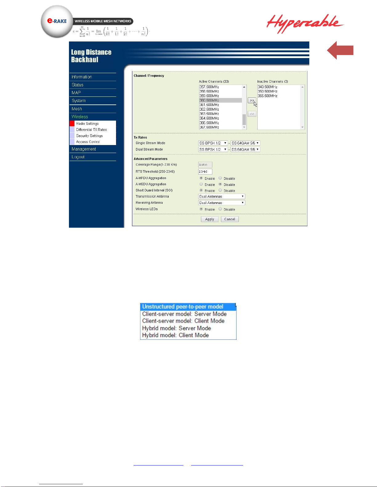
Topology Hybrid model:
Unstructured peer to peer model
Each mesh nodes is equal to each other, free connection by the best path.
Client-server model: Server mode
Server mode can be scanned and connected by Client-server model: client mode and
Hybrid model: client mode.
Client-server model: Client mode
Client mode can only connect to Client-server model: Server mode and Hybrid model:
Server mode.
Hybrid model: Server mode
Hybrid model: Server mode can connect to Client-server model: Client mode, Hybrid
model: Client mode and Unstructured peer to peer mode.
Page 29
www.hypercable.fr - www.e-rake.us.com
29
Hybrid model: Client mode
Hybrid model: Client mode can connect to Client-server model: Server mode, Hybrid
model: Server mode and Unstructured peer to peer mode.
Wireless Network Name (SSID):
Mesh nodes, Base station and CPEs in same network must have the same network name.
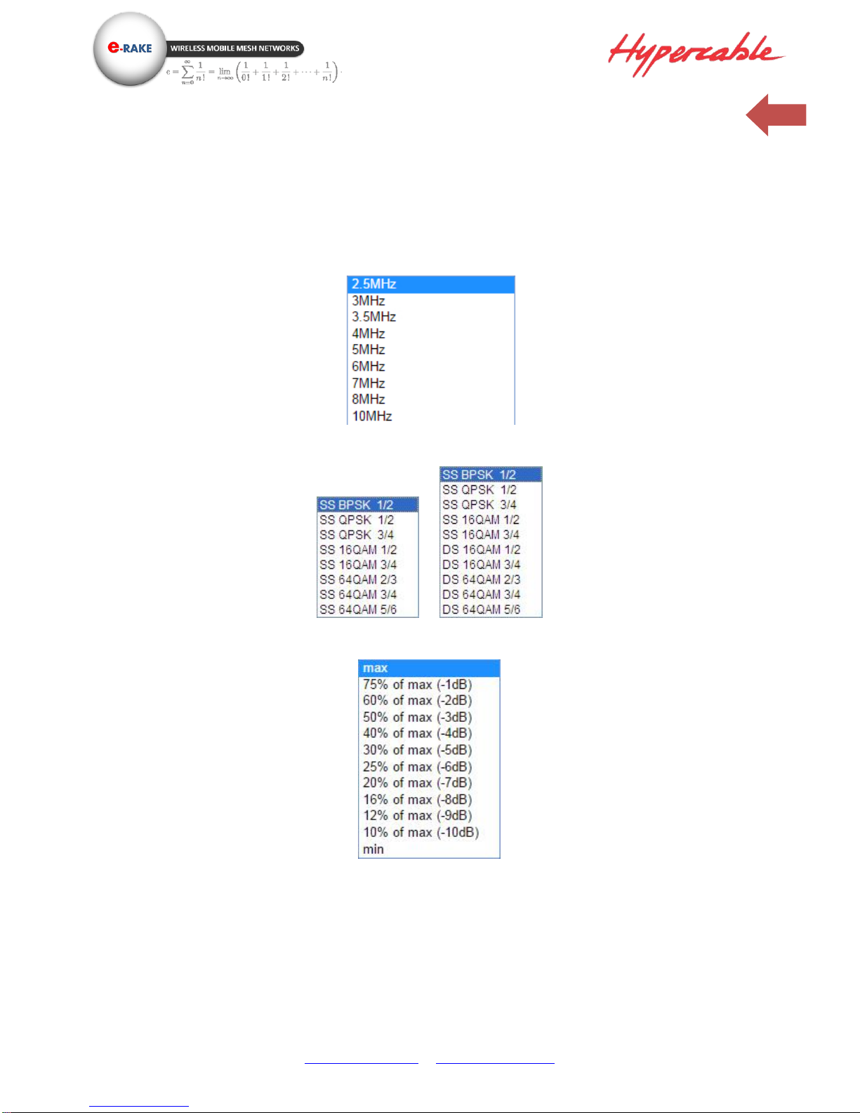
Modulation: HT-OFDM, high throughput OFDM modulation.
RF Bandwidth: Decide bandwidth of Radio Frequency. Including 2.5 / 3 / 3.5 / 4 / 5 / 6 / 7/ 8 / 10 /
MHz, default is 5 MHz.
Channel / Frequency: Set the operation frequency of the radio.
TX Rate Range: Here you can setup the min. Rate and max. Rate of the Tx Rate range.
TX Power: Setting power of TX, default is Max.
Coverage Range: The max. coverage range value will be changed by the channel BW, less channel
BW can transmit longer distance. Set the proper coverage range parameters is helpful to get the
stable link.
RTS Threshold: “Request to send” is the optional mechanism used by the 802.11 wireless networking
protocol to reduce frame collisions introduced by the hidden node problem. Set the packet size to
trigger RTS/CTS enable. This is normally set in base station side only because the hidden station
Page 30
www.hypercable.fr - www.e-rake.us.com
30
problem does not exit from the perspective of the AP. RTS Threshold can be set between 256 - 2346
bytes.
A-MPDU Aggregation: Aggregate MAC Service Data Unit. The concept of A-MPDU aggregation is to
join Multiple MPDU sub frames with a single leading PHY header. A key difference from A-MSDU
aggregation is that A-MPDU functions after the MAC header encapsulation process. This method
offer higher MAC throughput compare to A-MSDU.
A-MSDU Aggregation: Aggregate MAC Protocol Data Unit. The concept of A-MSDU is to allow
multiple MSDUs to be sent to the same receiver concatenated in a single MPDU. This supporting
function for A-MSDU within 802.11n is mandatory at the receiver. Due to Destination Address (DA)
and sender Address (SA) in the sub-frame header must match to same receiver address (RA) and the
transmitter address (TA) in the MAC header, A-MSDU cannot be used for broadcast & multicast.
Short Guard Interval (SGI): The guard interval is the space between symbols (characters)
being transmitted. Adding time between symbol transmissions allows these echoes and
reflections to settle in before the next symbol is transmitted. In normal 802.11 operations,
the guard interval is 800ns. In good link condition without interferences, enable the short
guard interval will short the time between symbol transmissions into 400ns to enhance the
efficiency of data transmission.
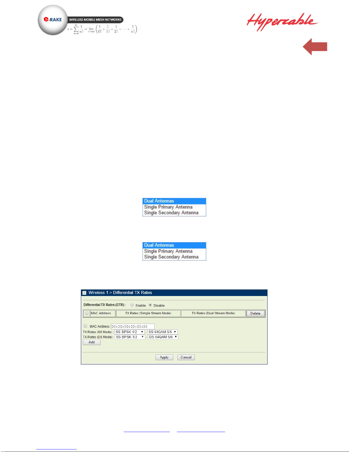
Transmission Antenna: There are 3 antenna options for selection
Receiving Antenna: Same as Transmission Antenna, there are 3 antenna options for selection too.
Wireless Setup / Differential Tx Rates
In this page, you can set the Differential Tx rates at fixed range.
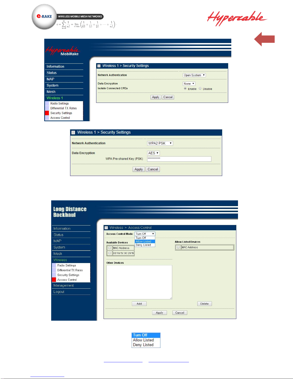
Wireless Setup / Security (This is NOT Available in Mesh mode)
Security/Cipher To prevent unauthorized radios from accessing data transmitted over the link, the
Encryption Settings window offers WPA2 PSK features, making your data transmission over air more
secure and allows you to specify Encryption Key(s).
Page 31
www.hypercable.fr - www.e-rake.us.com
31
Open System – without encryption
WPA2 PSK – AES encryption
Wireless Setup / Access control (This is NOT Available in Mesh mode)
You can enable the MAC address Access control feature and decide which mode you want to control,
Allow or Deny.
Page 32
www.hypercable.fr - www.e-rake.us.com
32
3-4 Management
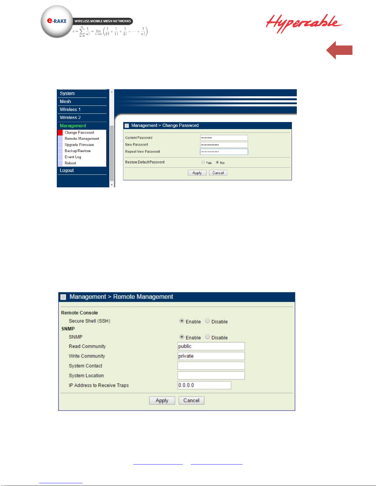
Management / Change Password
This page allow you to change password of the 300 MHz 4x4 MIMO HT-OFDM MESH Radio.
1. Key in the current password in the “Current Password” filed. Default password of this radio is
“password”
2. Key in the new password to the New Password field, and then type it again into the Repeat New
password field to confirm the new password.
3. Click the “Apply” button to active the settings.
4. You can restore to default password too by check the “yes” option.
Note: After you change password, please take note of your new password. Otherwise, you will not
able to access the radio with correct password.
Management / Remote Management
You can doing the remote Management via Secure Shell (SSH) or SNMP by setting the parameters in
this page.
Page 33
www.hypercable.fr - www.e-rake.us.com
33
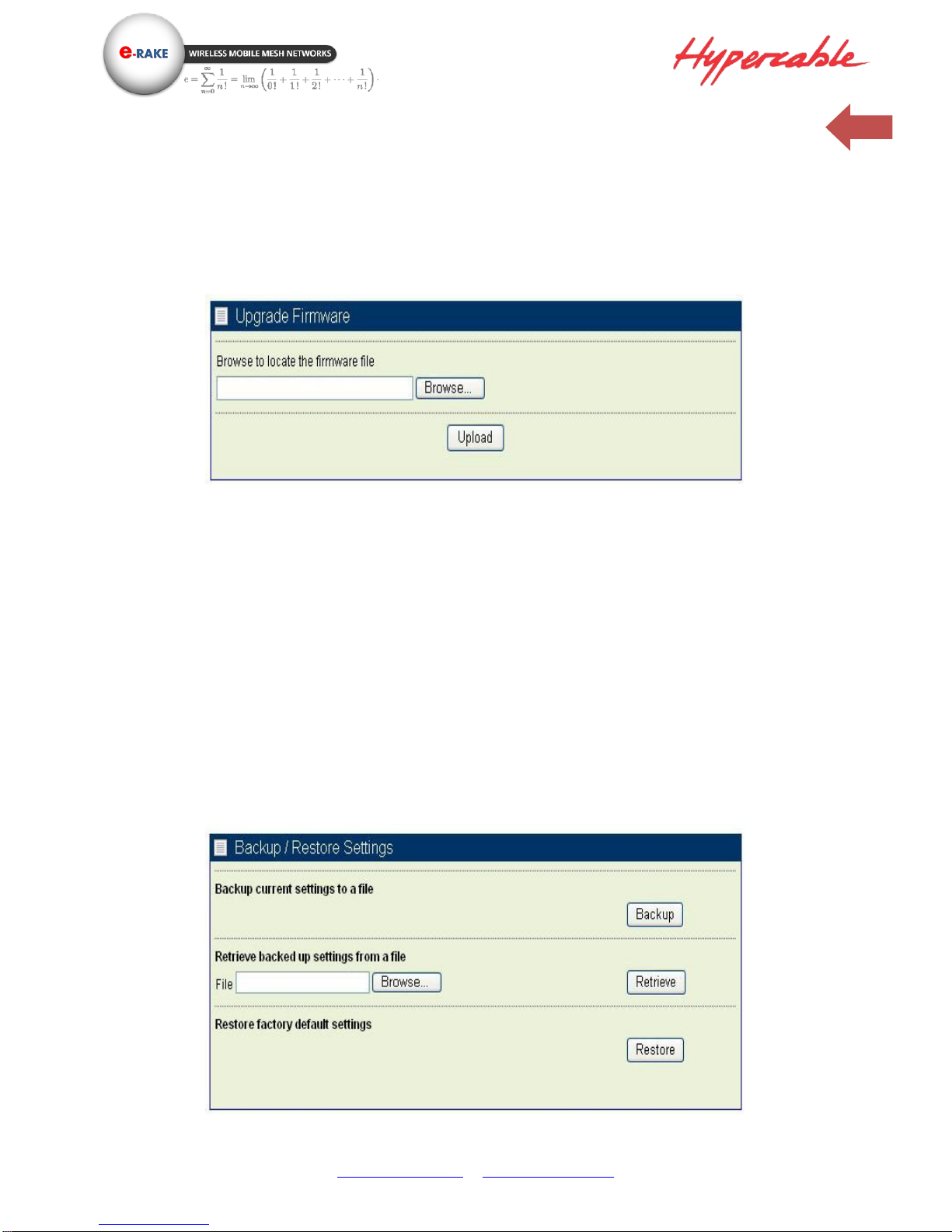
Management / Upgrade Firmware
The Upgrade Firmware menu will display the Upgrade Firmware page, you can update the latest
firmware to the 300 MHz 4x4 MIMO HT-OFDM MESH Radio.
Please make sure that you are using the latest and correct firmware before you doing the upgrade
procedure.
Below are the upgrade procedures:
Using browser to access the main page of the 300 MHz 4x4 MIMO HT-OFDM MESH Radio
1. Select “Upgrade Firmware” from the Management page.
2. Input the exact file path and name or select the file by clicking Browse button, then press Upload
button to upgrade the firmware.
3. Please wait for few seconds.
If download fail, please repeat the step 1~3 to download again.
Note! Do not power off the unit when it is being upgraded.
Management / Backup / Restore Settings
The current system settings can be saved into a file as a backup by clicking “Backup”. The saved file
can be loaded back on the radio by clicking “Browse”. When you have selected the settings file, click
“Retrieve” to begin the process. Furthermore, you may click “Restore” to factory default settings.
Page 34
www.hypercable.fr - www.e-rake.us.com
34
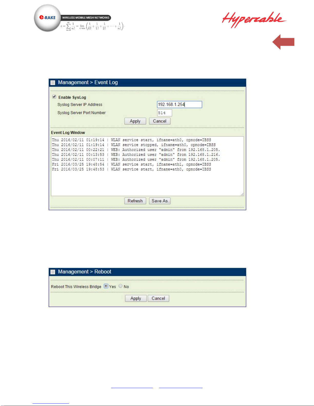
Management / Event Log
Enable SysLog if you have a Syslog Server on your network environment. If enable, you need to input
the Syslog Server IP Address (default is 0.0.0.0) and the port number your Syslog Server is configured
to use. The default port number is 514. The Event Log Window lists Wireless backhaul events. Click
on “Refresh” to update the network events or “Save As…” to save the event into a file on your
computer. Click “Apply” if you made any changes.
Management / Reboot
The Reboot screen enables you to reboot your 300 MHz 4x4 MIMO HT-OFDM MESH Radio if any
changes are made and you want to refresh the radio, you need to reboot the 300 MHz 4x4 MIMO HTOFDM MESH Radio Select the “Yes” check box and click “Apply”. It will take you about 50 seconds to
go through reboot. The Web-browser will not be accessible until the Wireless backhaul has finished
its reboot process.
Page 35
www.hypercable.fr - www.e-rake.us.com
35
Management / Logout
Click log out when you finished all the configuration, if there is anything missed, you can selected
“login again” to enter the configuration process again.
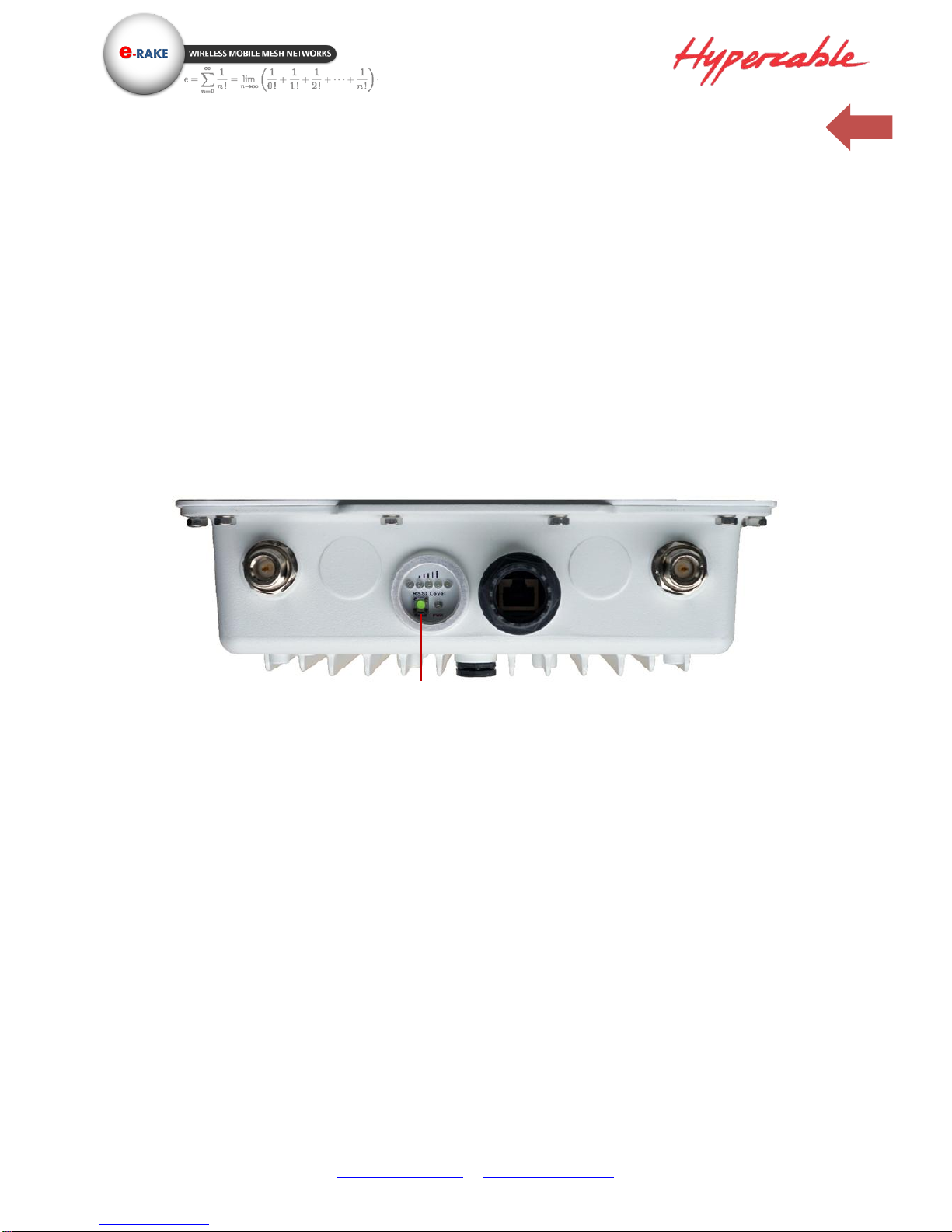
Hardware reset
If your Web User Interface stops responding, ping the IP address of the radio to check whether
“reply” is obtained, or unplug and then plug back in the power supply of the Radio. This will reboot
the Radio. If you are still unable to communicate with the Web User Interface, remove the plastic cap
in the left of radio’s bottom, Then use a stick to press in and hold the RESET button for 6~9 seconds.
This will reset the Radio to the factory default settings. If you applied any personal configuration
settings, you will need to make the changes again.
Reset button of the radio
Reset button
 Loading...