

Page 1
EarthLinked®
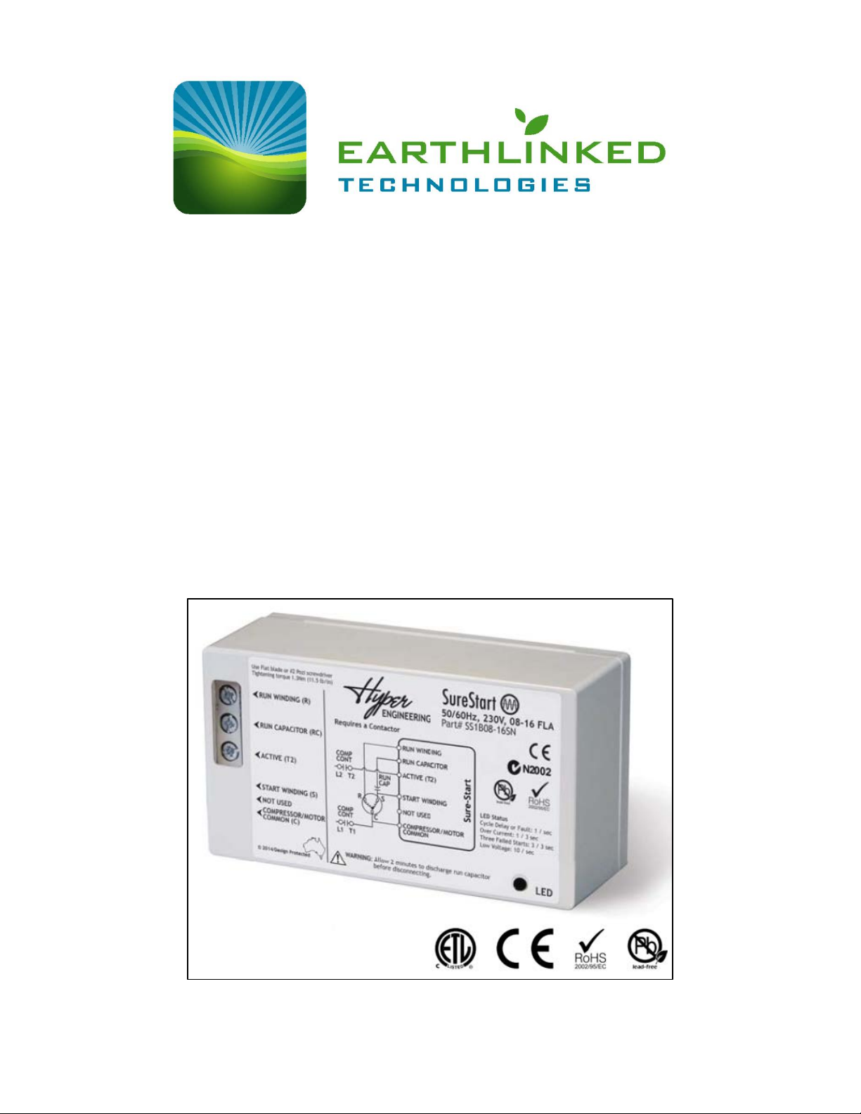
Sure-Start Module
Installation and Operation Manual
SS-IOM (05/14) Copyright 2014 Earthlinked Technologies, Inc.
Page 2

Disclaimer
Proper installation and servicing of th e Sure-Start Module is essential to the Heating and Cooling
System’s reliable performance. All EarthLinked® systems and modules must be installed and
serviced by an ETI authorized technician. Installation and service must be done in accordance with
the instructions set forth in this manual. Failure to provide installation and service by an ETI
authorized installer in a manner consistent with this manual will nullify the limited warranty coverage
for the system.
Earthlinked Technologies shall not be liable for any defect, unsatisfactory performance, damage or
loss, whether direct or consequential, relative to the design, manufacture, construction, application
or installation of field specified components.
Earthlinked Technologies, Inc.
4151 South Pipkin Road
Lakeland, Florida 33811
tel. 863-701-0096 ● fax 863-701-7796
info@earthlinked.com ● www.earthlinked.com
CSI # 23 80 00
SS-IOM (05/14) Page 2
Page 3
SureStart Features
Power Supply
System Nominal Capacity, Tons
ETI Model Sure-Start
230-3-60
2.0 Thru 6.0
SS2-2472
460-3-60
2.0 Thru 6.0
SS3-2472
SureStart is a soft starter targeted to reduce light flicker caused at startup by scroll compressor
motors. This control has innovations that include the following features:
• 60 to 70% reduction in direct in-rush current
• Under voltage protection
• Motor reversal protection
• Self-adjusts for optimal start performance
• 50/60 Hz compatible
• ETL, CE, EMC and RoHs compliant
• Tolerant to “dirty power” conditions
• Fault LED
• Internal current limiting
Pre-Installation
Check Figure 1 to ensure that you have the correct ETI Model Sure-Start for the EarhLinked®
System power supply and nominal tonnage rating.
Figure 1 is valid for R-410A, R-407C and R-22 EarhLinked
230-1-60 1.5 Thru 2.5 SS1-1830
230-1-60 3.0 Thru 6.0 SS1-3672
®
Systems.
240-1-50 1.5 Thru 2.0 SS1-1824
240-1-50 2.5 Thru 6.0 SS1-3060
400-3-50 2.0 Thru 6.0 SS5-2472
Figure 1. EarthLinked® System and Sure-Start Model Match
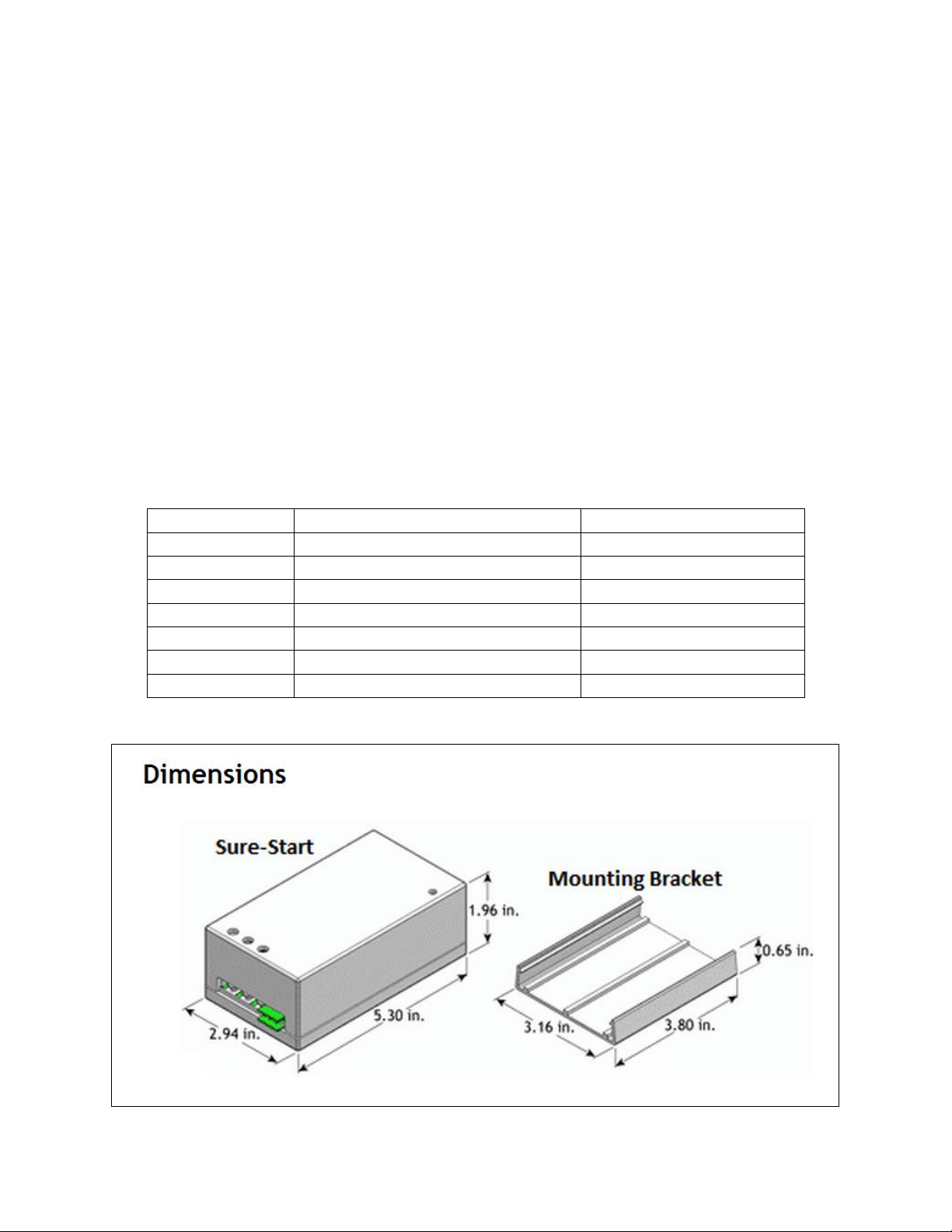
Figure 2. Sure-Start Module and Mounting Bracket Dimensions
SS-IOM (05/14) Page 3
Page 4
Installation
IMPORTANT!
1. Before installling the Sure-Start on the EarthLinked® Compressor Unit, turn all power to the
system OFF.
2. Remove the approporate compressor unit cabinet panels to access the electric box.
3. Prior to installation of the Sure-Start, be sure all start capacitors, start relays, hard start (start
assist) and/or other related devices are removed.
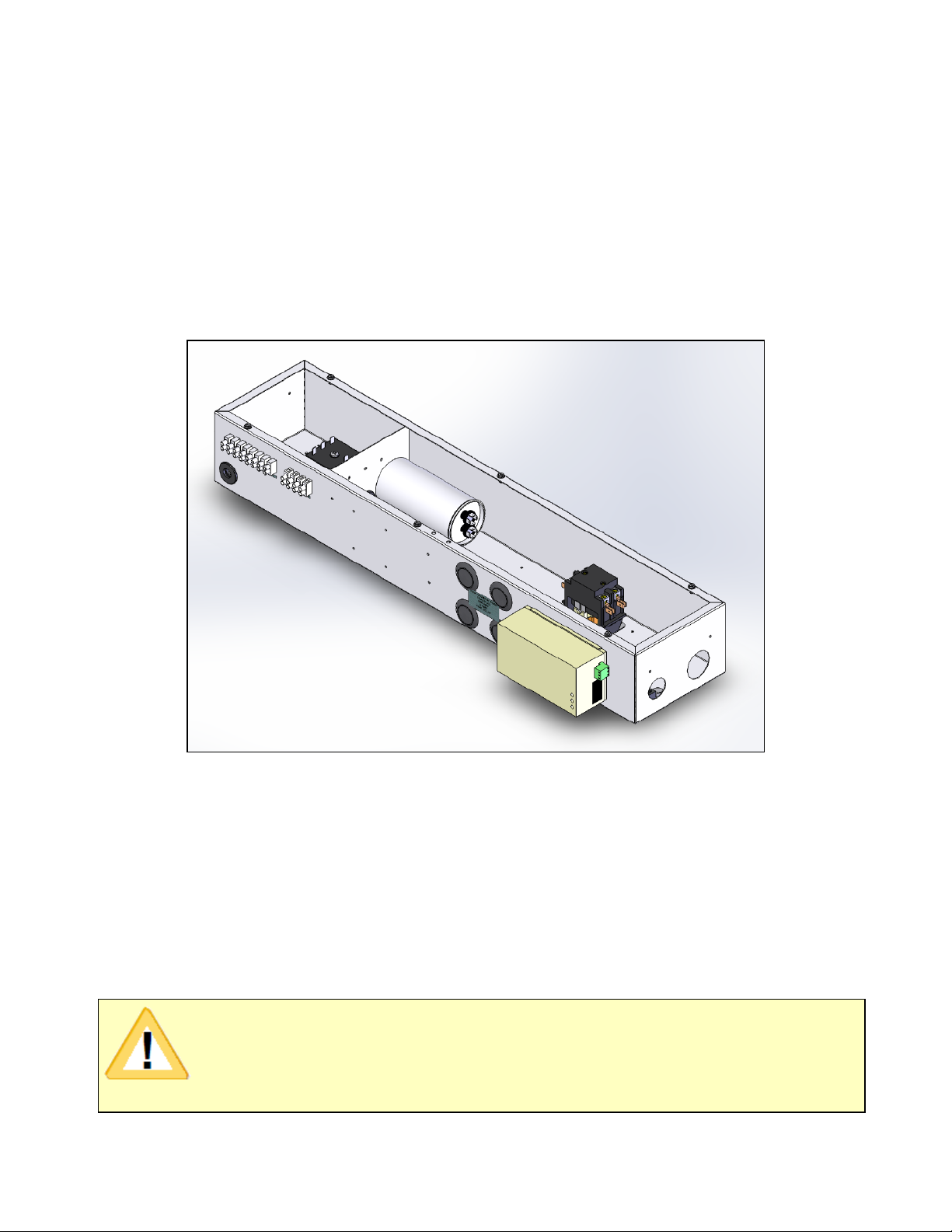
4. Install the Sure-Start module mounting bracket as shown in Figure 3. The mounting bracket is
to be fastened to the outside of the electric box with two self-tapping screws. BE SURE NOT
TO DRILL INTO ELECTRICAL COMPONE NTS INSIDE THE ELECTRIC BOX. REMOVE ALL
METAL SHAVINGS.
Figure 3. Mounting Bracket Installation
5. Wire as shown in Figure 4 and Figure 5, as appropriate. All wiring to and from the components
inside the electric box can be channeled through an access hole in the bottom of the electric
box.
6. Wiring is field supplied. All field wiring shall be rated at 167°F (75°C). Wire gage shall be as
follows:
a. 8 to 12 AWG Cu, stranded, for terminals [Run Winding (R) and active T2]
b. 12 to 16 AWG Cu, stranded, for terminals [Run Capacitor (RC), Start Winding (S)
and Compressor/Motor Common (C)]
DO NOT SWAP THE RUN AND START WINDINGS!
BE SURE THE CONNECTOR TERMINATIONS ARE TIGHT!
SS-IOM (05/14) Page 4
Page 5
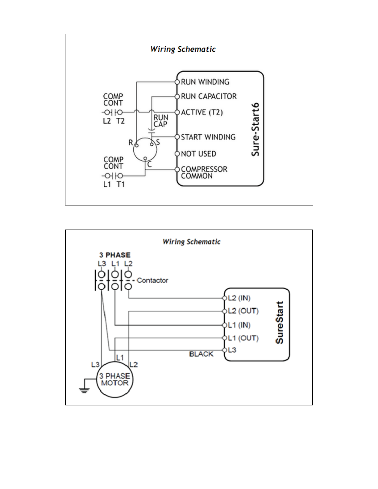
Figure 4. Single Phase Wiring Schematic
Figure 5. Three Phase Wiring Schematic
7. Check all connections to see that they are correct and tight. Reassemble compresor unit
cabinet panels and apply power to the equipment. Cycle the EarthLinked
®
System to ensure
proper operation. The Sure-Start module could take up to six (6) starts to optimize the system.
SS-IOM (05/14) Page 5
Page 6

SureStart Operation
When the system control calls for compressor operation, the compressor contactor will energize. If
the supply voltage is less than “minimum startup voltage”, a 50 second delay is initiated. At the end
of the delay, another attempt will be made to start the compressor unless the supply voltage
remains unchanged. See Figure 6 for the SureStart Mode of Operation.
SureStart uses an optimized starting process that learns the starting characteristics of the
compressor to further refine the starting cycle on each recurring start.
If the compressor fails to start, the module will terminate the start attempt after 1 second and initiate
a 3 minute lockout before attempting a restart.
While the compressor is running, if supply voltage falls below the “shutdown on low voltage” limit for
2 seconds, SureStart will stop the compressor and initiate a 3 minute lockout. A restart will be
initiated after 3 minutes if the supply voltage is equal to or greater than the “minimum startup
voltage”. This is done to protect the compressor against a sudden drop in supply voltage.
SureStart is able to detect an interruption in power, when the interruption is 0.1 seconds or longer.
When a power interruption is detected, it will shut down the compressor for 3 minutes. A power
interruption that is shorter than 0.1 seconds may result in the compressor running backwards.
SureStart is able to determine if the compressor is running backwards. If this condition is detected,
the control will stop the compressor for 3 minutes before restart is initiated.
If the run capacitor is faulty or has failed, SureStart will shut down the compressor for 3 minutes
before initiating a restart.
SS-IOM (05/14) Page 6
Page 7
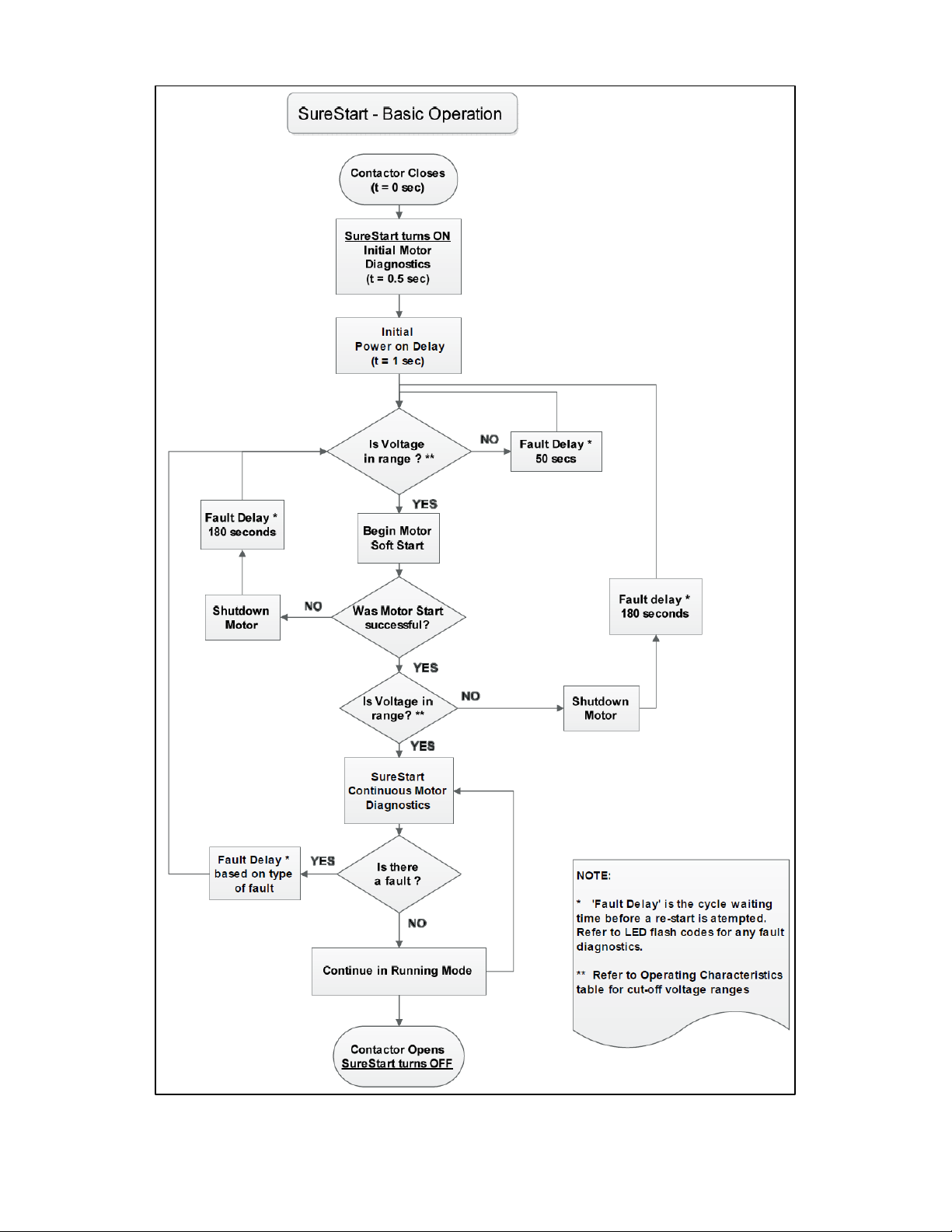
Figure 6. SureStart Mode of Operation
SS-IOM (05/14) Page 7
Page 8
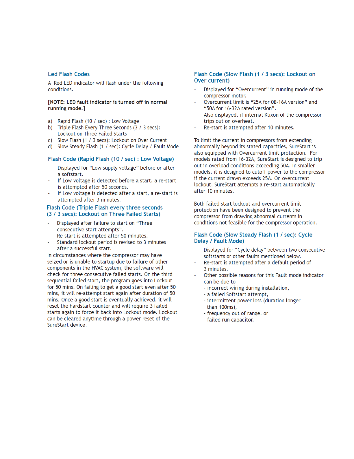
Single - Phas e LED Flas h Code s
SS-IOM (05/14) Page 8
Page 9
SS-IOM (05/14) Page 9
 Loading...