

HYOSUNG GV250 EI, GT250R EI, GT250 EI Service Manual
SERVICE MANUAL
99000-95620
SERVICE MANUAL
NOTE
『』
model :
『』
model :
FOREWORD
This manual contains an introductory description on
HYOSUNG
『』
&
『』
and
procedures for its inspection / service and overhaul
of its main components.
It covers the differences from Carbure type and
please refer to the service manual of
『
(99000-95310)』,
『 &
(99000HR8310)』and
『&
(99000-94710)』for others which are not covered in
this manual.
Other information considered as generally known is
not included.
Read GENERAL INFORMATION section to
familiarize yourself with outline of the vehicle and
MAINTENANCE and other sections to use as a guide
for proper inspection and service.
This manual will help you know the vehicle better so
that you can assure your customers of your optimum
and quick service.
ELECTRICAL SYSTEM
GROUP INDEX
GENERAL INFORMATION
1
EI SYSTEM DIAGNOSIS
FUEL SYSTEM AND THROTTLE BODY
4-2
4-1
5
SERVICING INFORMATION
7
This manual has been prepared on the basis
of the latest specification at the time of
publication.
If modification has been made since then,
difference may exist between the content of
this manual and the actual vehicle.
Illustrations in this manual are used to show
the basic principles of operation and work
procedures.
They may not represent the actual vehicle
exactly in detail.
WARNING
This manual is intended for those who have
enough knowledge and skills for servicing
HYOSUNG vehicles. Without such knowledge and
skills, you should not attempt servicing by relying
on this manual only.
Instead, please contact your nearby authorized
HYOSUNG motorcycle dealer.
COPYRIGHT S&T Motors Co., Ltd.
2
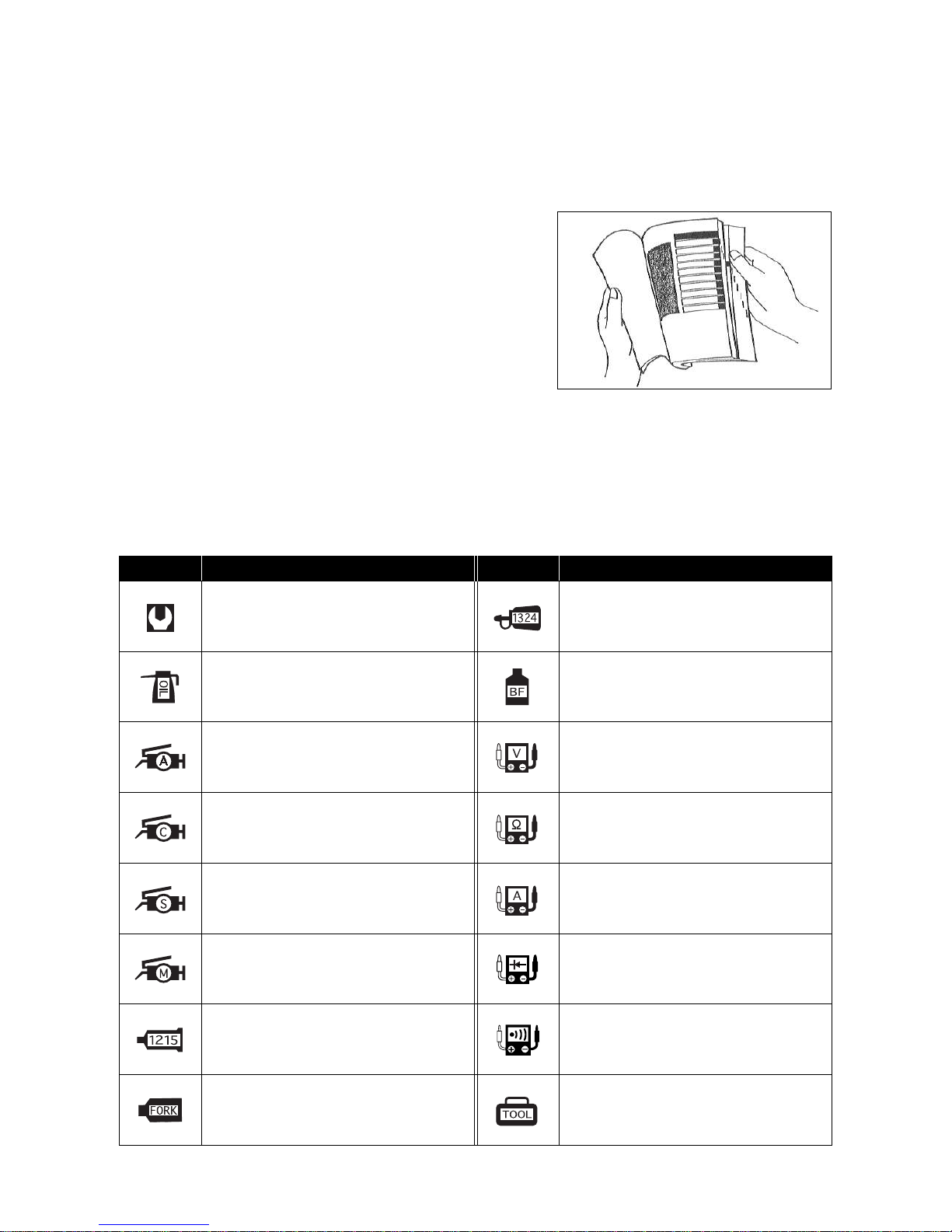
HOW TO USE THIS MANUAL
TO LOCATE WHAT YOU ARE
LOOKING FOR :
1. The text of this manual is divided into sections.
2. As the title of these sections are listed on the previous
page as GROUP INDEX, select the section where you are
looking for.
3. Holding the manual as shown at the right will allow you to
find the first page of the section easily.
4. On the first page of each section, its contents are listed.
Find the item and page you need.
SYMBOL
Listed in the table below are the symbols indicating instructions and other information necessary for servicing.
The meaning of each symbol is also included in the table.
Apply THREAD LOCK “1324”.
Apply or use brake fluid.
Measure in voltage range.
Measure in resistance range.
Measure in current range.
Use special tool.
Measure in continuity test range.
Measure in diode test range.
Torque control required.
Data beside it indicates specified torque.
Apply oil.
Use engine oil unless otherwise specified.
Apply SUPER GREASE “A”.
Apply SILICONE GREASE.
Apply MOLY PASTE.
Apply BOND “1215”.
Use fork oil.
DEFINITION
SYMBOL
DEFINITIONSYMBOL
Apply SUPER GREASE “C”.

3
A
ABDC : After Bottom Dead Center
AC : Alternating Current
API : American Petroleum Institute
A TDC : After Top Dead Center
B
BBDC : Before Bottom Dead Center
BDC : Bettom Dead Center
BTDC : Before Top Dead Center
D
DC : Direct Current
DOHC : Double Over Head Camshaft
E
ECU : Engine Control Unit,
EI Control Unit
EI : Electric fuel Injection,
Electric fuel Injector
ET Sensor : Engine Temperature Sensor
(ETS)
F
FP : Fuel Pump
G
GP Switch : Gear Position Switch
I
IAP Sensor : Intake Air Pressure Sensor
(IAPS)
IA T Sensor : Intake Air Temperature Sensor
(IA TS)
IG : Ignition
ISC Solenoid : Idle Speed Control Solenoid
L
LCD : Liquid Crystal Display
LED : Light Emitting Diode
LH : Left Hand
M
Max : Maximum
Min : Minimum
O
O2 Sensor : Oxygen Sensor (O2S)
R
RH : Right Hand
RO Switch : Roll Over Switch
S
SAE :
Society of Automotive Engineers
SA V Solenoid : Secondary Air V alve Solenoid
T
TDC : Top Dead Center
TP Sensor : Throttle Position Sensor (TPS)
ABBREVIATIONS USED IN THIS MANUAL

4
BL : Black with Blue tracer BBr : Black with Brown tracer
BG : Black with Green tracer BO : Black with Orange tracer
BR : Black with Red tracer BW : Black with White tracer
BY : Black with Yellow tracer LB : Blue with Black tracer
LG : Blue with Green tracer LR : Blue with Red tracer
L W : Blue with White tracer L Y : Blue with Y ellow tracer
BrB : Brown with Black tracer BrW : Brown with White tracer
GB : Green with Black tracer GR : Green with Red tracer
GY : Green with Yellow tracer GrB : Gray with Black tracer
GrR : Gray with Red tracer GrW : Gray with White tracer
OB : Orange with Black tracer OL : Orange with Blue tracer
OG : Orange with Green tracer OR : Orange with Red tracer
OW : Orange with White tracer OY : Orange with Yellow tracer
RB : Red with Black tracer RW : Red with White tracer
WB : White with Black tracer WL : White with Blue tracer
WR : White with Red tracer YB : Yellow with Black tracer
YL : Yellow with Blue tracer YG : Yellow with Green tracer
YR : Yellow with Red tracer
B : Black Gr : Gray Sb : Light blue
L : Blue Lg : Light green W : White
Br : Brown O : Orange Y : Yellow
G : Green R : Red
WIRE COLOR
5
GENERAL INFORMATION
EXTERIOR PHOTOGRAPH ………………………………………………………… 6 (1-6-1)
EXTERIOR ILLUSTRATION
~~ ₩₩
……………………………… 8 (1-6-3)
EXTERIOR ILLUSTRATION
~~ ₩₩
…………………………… 9 (1-7-1)
EXTERIOR ILLUSTRATION
~~ ₩₩
………………………………… 10 (1-7-2)
FUNCTION OF EI SENSOR ………………………………………………………… 11 (1-8-1)
SPECIFICATIONS ……………………………………………………………………… 12 (1-8-2)
CONTENTS
1
6
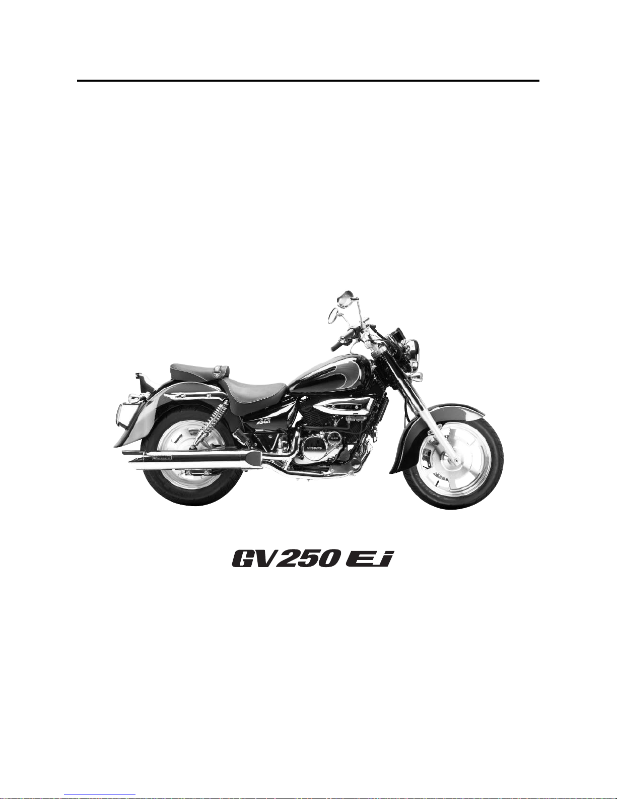
1-6-1 GENERAL INFORMATION
EXTERIOR PHOTOGRAPH
7
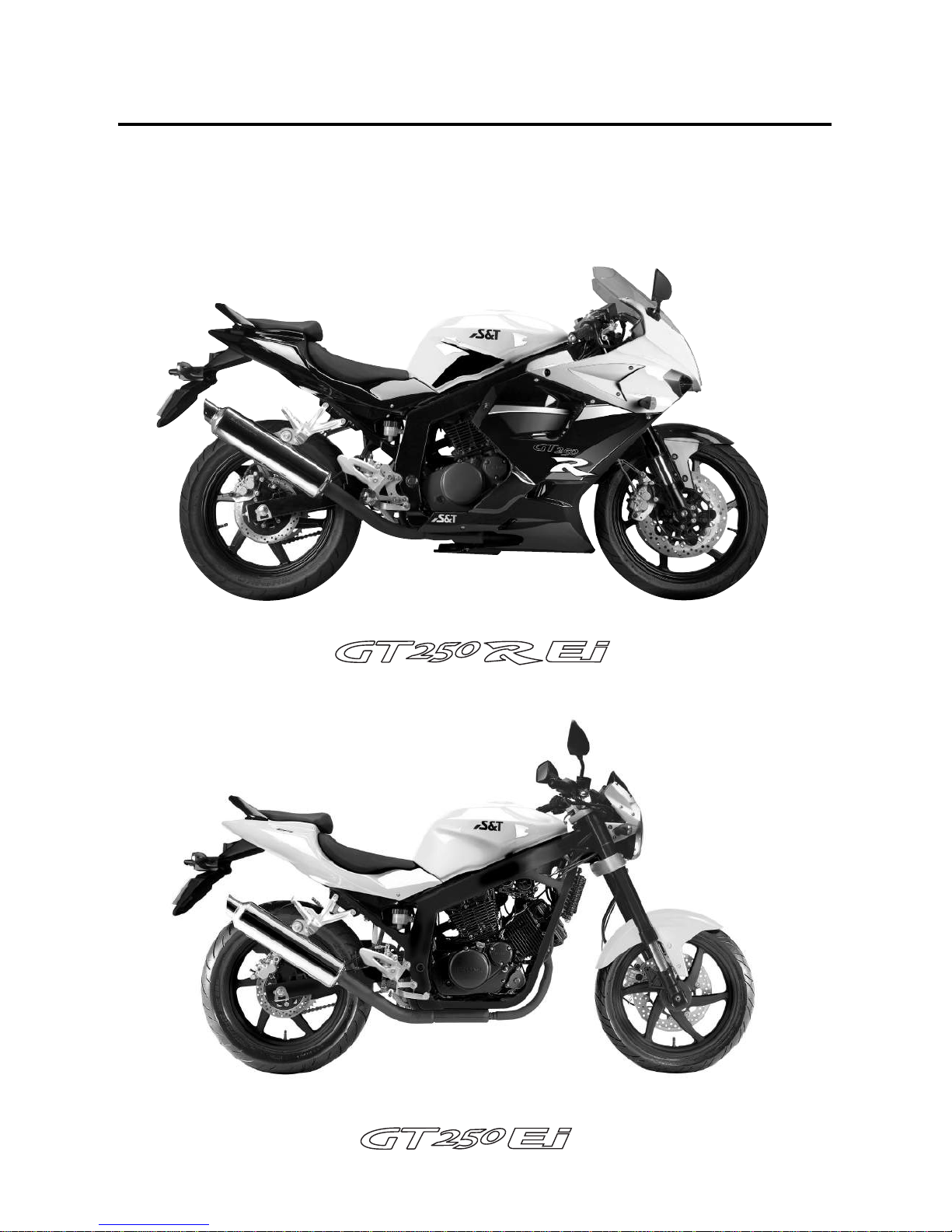
GENERAL INFORMATION 1-6-2
EXTERIOR PHOTOGRAPH
8
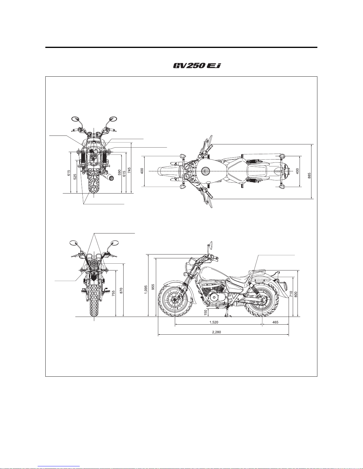
1-6-3 GENERAL INFORMATION
EXTERIOR ILLUSTRATION
~~ ₩₩
Rear
reflector
Brake / Tail lamp
Rear turn signal lamp
License plate lamp
Front turn signal lamp
Passenger footrests
Head lamp
(HEIGHT)
(WHEEL BASE)
(LENGTH)
(WIDTH)
9
GENERAL INFORMATION 1-7-1
EXTERIOR ILLUSTRATION
~~ ₩₩
Rear
reflector
Brake / Tail lamp
License plate lamp
Rear turn signal lamp
Front turn signal lamp
Passenger footrests
Head lamp
(HEIGHT)
(WHEEL BASE)
(LENGTH)
(WIDTH)
10
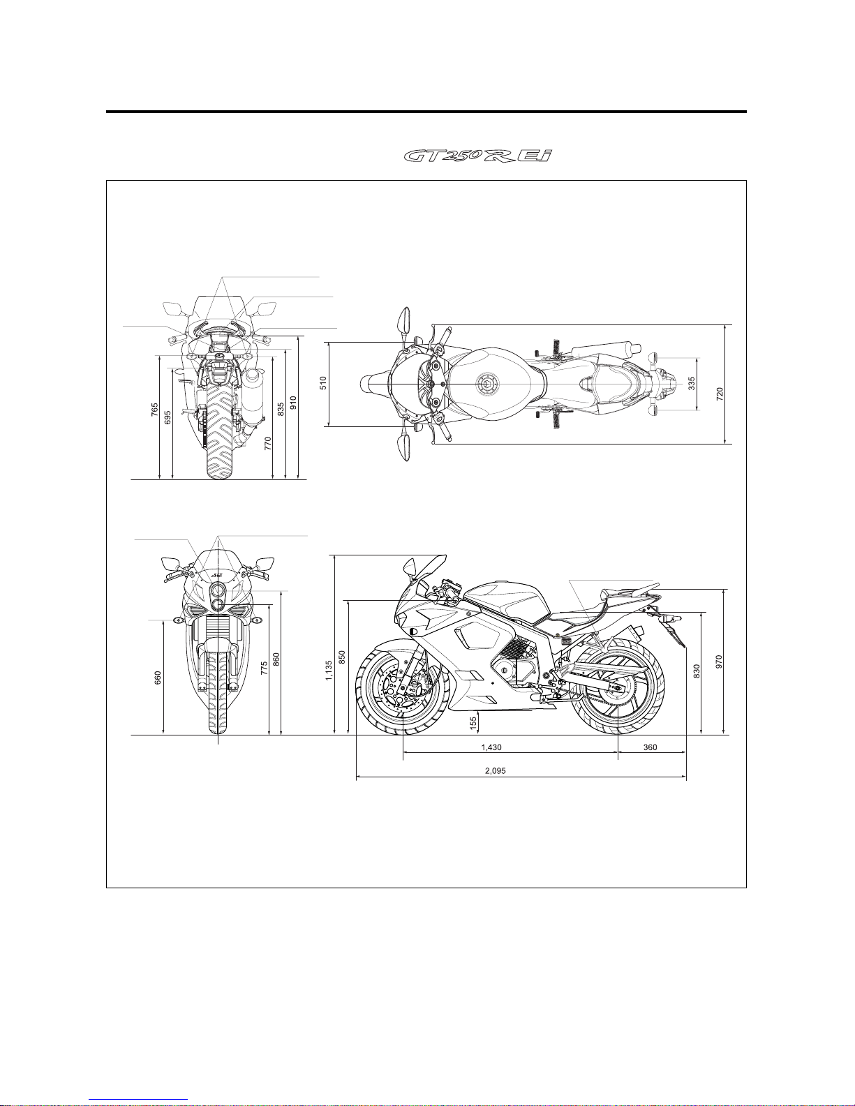
1-7-2 GENERAL INFORMATION
EXTERIOR ILLUSTRATION
~~ ₩₩
Rear
reflector
Brake / Tail lamp
License plate lamp
Rear turn signal lamp
Front turn signal lamp
Passenger footrests
Head lamp
(HEIGHT)
(WHEEL BASE)
(LENGTH)
(WIDTH)

11
GENERAL INFORMATION 1-8-1
FUNCTION OF EI SENSOR
★★
ECU (Engine Control Unit, EI Control Unit)
: ECU decide the fuel injection volume and ignition time to adjust the fuel injector opening and closing rate
which is considered the engine speed, intake air pressure, intake air volume, engine temperature, oxygen
volume and throttle opening angle, etc.
★★
EI (Electric fuel Injector)
: EI spray the fuel to intake pipe by ECU’s injection signal.
Fuel which is needed combustion in the combustion chamber is supplied from the fuel tank.
★★
ET sensor (Engine Temperature Sensor : ETS)
: ET sensor communicate the perceived engine temperature to ECU.
ET sensor is located the outside of the cylinder to measure the engine temperature.
★★
GP switch (Gear Position Switch)
: GP switch is used when start / stop and control ECU as the converted electrical signal of the gear position is
supplied ECU.
★★
IAP sensor (Intake Air Temperature : IAPS)
: IAP sensor measure the pressure which is generated from the intake pipe and compare with the provided
absolute pressure, then analogize the air volume indirectly and help to work the fuel injector properly.
★★
IAT sensor (Intake Air Temperature Sensor : IATS)
: IAT sensor perceive the atmospheric temperature and is located the air cleaner case.
★★
ISC solenoid (Idle Speed Control Solenoid)
: ISC solenoid is interlocked with the throttle body, so ECU control the engine idle speed.
★★
O2 sensor (Oxygen Sensor : O2S)
:O2 sensor measure the oxygen volume from the exhaust gas and convert the oxygen volume into voltage
value, then communicate the output voltage to ECU.
★★
Pick-up Coil
: Pick-up coil perceive the front and rear cylinder’s engine speed and realtime of piston position.
★★
RO switch (Roll Over Switch)
: RO switch is the fuel cut-off system when the motorcycle is leaned over 60°for upset accident.
★★
SAV solenoid (Secondary Air Valve Solenoid)
: SAV solenoid supply the fresh air to the exhaust pipe for decrease of the exhaust gas.
★★
TP sensor (Throttle Position Sensor : TPS)
: TP sensor detect the throttle opening angle and is located the throttle body.
It decide the fuel injection volume and compensate the ignition time as inform idle·acceleration·
deceleration condition and throttle full opening etc. to ECU.
12
1-8-2 GENERAL INFORMATION
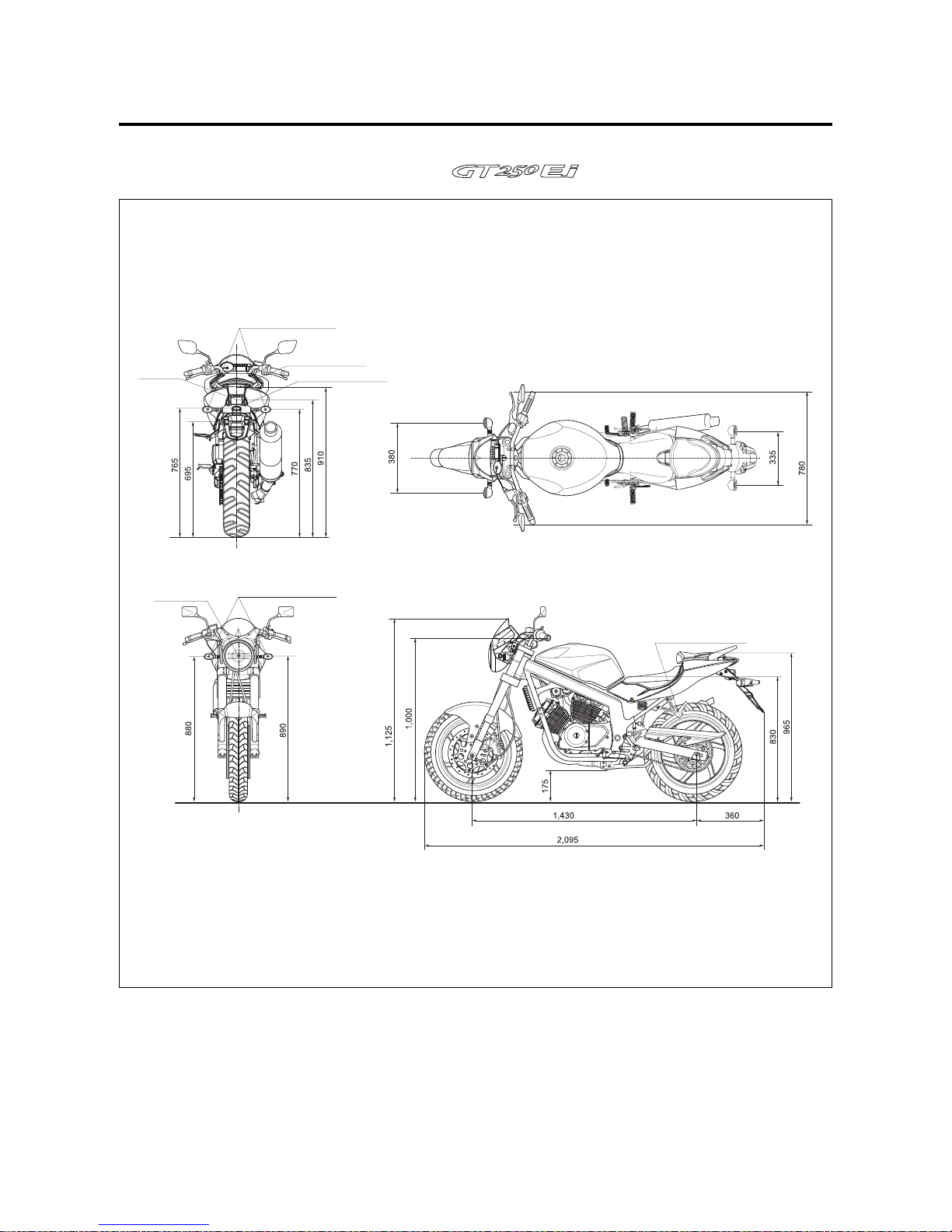
2,280 mm (89.8 in)
885 mm (34.8 in)
1,095 mm (43.1 in)
1,520 mm (59.8 in)
150 mm (5.9 in)
175 kg (386 lbs)
2,095 mm (82.5 in)
720 mm (28.4 in)
1,135 mm (44.7 in)
1,430 mm (56.3 in)
155 mm (6.1 in)
185 kg (408 lbs)
Overall length
Overall width
Overall height
Wheelbase
Ground clearance
Mass
ITEM
SPECIFICATIONS
⊙⊙
DIMENSIONS AND MASS
Four-stroke, DOHC,
air-cooled and oil-cooled
V-2 cylinder
57.0 mm (2.24 in)
48.8 mm (1.92 in)
249 ㎤(15.2 in3)
Electric fuel Injection
Electric starter
Wet sump
←
←
←
←
←
←
←
←
←
←
←
←
←
←
←
←
Type
Number of cylinder
Bore
Stroke
Piston displacement
Fuel system
Starter system
Lubrication system
ITEM
⊙⊙
ENGINE
Wet multi-plate type
5-speed constant mesh
1-down, 4-up
3.290
2.460
1.560
1.190
0.960
0.840
520HO, 116 links
←
←
←
←
←
←
←
←
←
520HO, 112 links
←
←
←
←
←
←
←
←
←
←
Clutch
Transmission
Gearshift pattern
Reduction ratio
1st
2nd
3rd
4th
5th
Drive chain
ITEM
⊙⊙
TRANSMISSION
←
780 mm (30.7 in)
1,125 mm (44.3 in)
←
175 mm (6.9 in)
175 kg (386 lbs)
Gear ratio
13
GENERAL INFORMATION 1-9
NOTE
The specifications are subject to change without notice.
Telescopic type
Swingarm type
40˚(right & left)
34˚
142 mm (5.59 in)
Disk brake
Drum brake
110/90 - 16 59S
150/80 - 15M/C 70S
120 mm (4.72 in)
←
←
27˚(right & left)
25.5˚
90 mm (3.54 in)
Double disk brake
Disk brake
110/70 - 17 54H
150/70 - 17 69H
←
←
←
←
←
←
Disk brake
←
←
←
←
Front suspension
Rear suspension
Steering angle
Caster
Trail
Front brake
Rear brake
Front tire size
Rear tire size
Front fork stroke
ITEM
⊙⊙
CHASSIS
ITEM
⊙⊙
ELECTRICAL
14.0 ℓ
1,450 ㎖
1,500 ㎖
1,800 ㎖
260 cc
17.0 ℓ
←
←
←
400 ±2.5 cc
←
←
←
←
←
Fuel tank
Engine oil
Front fork oil capacity (One side)
Oil change
Oil and filter change
Engine overhaul
ITEM
⊙⊙
CAPACITIES
Ignition type
Ignition timing
Spark plug
Battery
Fuse
Head lamp
Turn signal lamp
Brake / Tail lamp
License plate lamp
Illumination lamp
High beam indicator lamp
Turn signal indicator lamp(right & left)
Neutral indicator lamp
Fuel meter lamp
“FI”(Fuel Injection) check lamp
ECU
13˚B.T.D.C. at 2,000 rpm and
30˚B.T.D.C. at 6,000 rpm
CR8E
12 V 10 Ah (MF)
30 A & 15 A
12 V - H4 : 60 W ×1
12 V - H4 : 55 W ×1
12 V - RY10 W × 4
12 V - P21/5 W × 1
12 V - W5 W × 1
12 V - 1.7 W × 2
12 V - 1.7 W × 1
12 V - 1.7 W × 2
12 V - 1.7 W × 1
12 V - 1.7 W × 1
LED type
←
←
←
←
←
12 V - H1 : 55 W ×1
12 V - H3 : 55 W ×1
←
LED type
←
LED type
LED type
LED type
LED type
LED type (Level type)
←
←
←
←
←
←
12 V - H4 : 60 W ×1
12 V - H4 : 55 W ×1
←
←
←
←
←
←
←
←
←
HI
LO
※ LED : Light Emitting Diode

14
15
PRECAUTIONS IN SERVICING
………………………………………
16 (4-1-1)
EI SYSTEM TECHNICAL FEATURES
………………………………
20 (4-1-5)
SELF-DIAGNOSIS FUNCTION
~~ ₩₩
………………
27 (4-1-12)
SELF-DIAGNOSIS FUNCTION
~~ ₩₩
…………………
29 (4-1-14)
EI SYSTEM TROUBLESHOOTING
…………………………………
33 (4-1-18)
CUSTOMER COMPLAINT ANALYSIS
…………………………………
33 (4-1-18)
SELF-DIAGNOSTIC PROCEDURES
…………………………………
35 (4-1-20)
SELF-DIAGNOSIS RESET PROCEDURE
……………………………
36 (4-1-21)
MALFUNCTION CODE AND DEFECTIVE CONDITION
……………
37 (4-1-22)
““
C12””PICK-UP COIL CIRCUIT MALFUNCTION
……………………
39 (4-1-24)
““
C14””TP SENSOR CIRCUIT MALFUNCTION
………………………
40 (4-1-25)
““
C15””ET SENSOR CIRCUIT MALFUNCTION
………………………
43 (4-1-28)
““
C17
””oorr““
C18””IAP SENSOR CIRCUIT MALFUNCTION
……………
45 (4-1-30)
““
C21””IAT SENSOR CIRCUIT MALFUNCTION
………………………
47 (4-1-32)
““
C22””OXYGEN SENSOR CIRCUIT MALFUNCTION
………………
49 (4-1-34)
““
C23””RO SWITCH CIRCUIT MALFUNCTION
………………………
50 (4-1-35)
““
C24
””oorr““
C25””IGNITION COIL MALFUNCTION
……………………
51 (4-1-36)
““
C27””ISC SOLENOID RANGE ABNORMAL
………………………
52 (4-1-37)
““
C31””GP SWITCH CIRCUIT MALFUNCTION
………………………
53 (4-1-38)
““
C32
””oorr““
C33””FUEL INJECTOR CIRCUIT MALFUNCTION
………
54 (4-1-39)
““
C37””SAV SOLENOID MALFUNCTION
……………………………
56 (4-1-41)
““
C41””FUEL PUMP RELAY CIRCUIT MALFUNCTION
………………
57 (4-1-42)
““
C43””OXYGEN SENSOR HEATER CIRCUIT MALFUNCTION
……
58 (4-1-43)
SENSORS
…………………………………………………………………
59 (4-1-44)
4 -1
EI SYSTEM DIAGNOSIS
CONTENTS
16
PRECAUTIONS IN SERVICING
When handling the component parts or servicing the
EI system, observe the following points for the safety
of the system.
⊙⊙
ELECTRICAL PARTS
▣▣
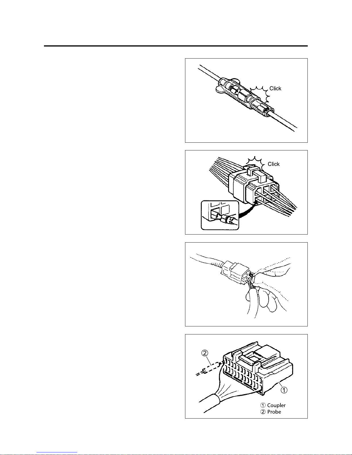
CONNECTOR / COUPLER
● When connecting a connector, be sure to push it
in until a click is felt.
● With a lock type coupler, be sure to release the
lock when disconnecting, and push it in fully till the
works when connecting it.
● When disconnecting the coupler, be sure to hold
the coupler body and do not pull the lead wires.
● Inspect each terminal on the connector / coupler
for looseness or bending.
● Inspect each terminal for corrosion and
contamination.
The terminals must be clean and free of any
foreign material which could impede proper
terminal contact.
● Inspect each lead wire circuit for poor connection
by shaking it by hand lightly. If any abnormal
condition is found, repair or replace.
● When taking measurements at electrical
connectors using a tester probe, be sure to insert
the probe from the wire harness side (backside) of
the connector / coupler.
4-1-1 EI SYSTEM DIAGNOSIS
17
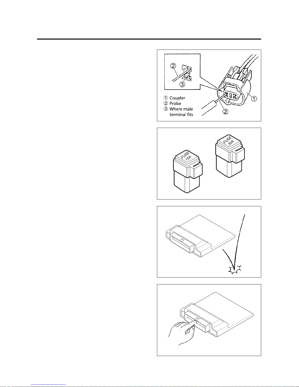
EI SYSTEM DIAGNOSIS 4-1-2
● When connecting meter probe from the terminal
side of the coupler (connection from harness side
not being possible), use extra care not to force
and cause the male terminal to bend or the female
terminal to open.
Connect the probe as shown to avoid opening of
female terminal.
Never push in the probe where male terminal is
supposed to fit.
● Check the male connector for bend and female
connector for excessive opening. Also check the
coupler for locking (looseness), corrosion, dust,
etc.
⊙⊙
FUSE
● When a fuse blows, always investigate the cause
to correct it and then replace the fuse.
● Do not use a fuse of a different capacity.
● Do not use wire or any other substitute for the
fuse.
⊙⊙
ECU / VARIOUS SENSORS
● Since each component is a high-precision part,
great care should be taken not to apply any sharp
impacts during removal and installation.
● Be careful not to touch the electrical terminals of
the ECU.
The static electricity from your body may damage
this part.
18
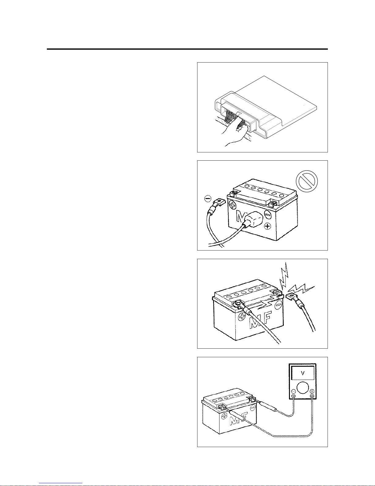
4-1-3 EI SYSTEM DIAGNOSIS
INCORRECT
● When disconnecting and connecting the ECU,
make sure to turn “OFF” the ignition switch, or
electronic parts may get damaged.
● Battery connection in reverse polarity is strictly
prohibited.
Such a wrong connection will damage the
components of the EI system instantly when
reverse power is applied.
● Removing any battery terminal of a running
engine is strictly prohibited.
The moment such removal is made, damaging
counter electromotive force will be applied to the
ECU which may result in serious damage.
● Before measuring voltage at each terminal, check
to make sure that battery voltage is 11 V or
higher.
Terminal voltage check at low battery voltage will
lead to erroneous diagnosis.

19
EI SYSTEM DIAGNOSIS 4-1-4
● Never connect an ohmmeter to the ECU with its
coupler connected. If attempted, damage to ECU
or sensors may result.
● Be sure to use a specified voltmeter / ohmmeter.
Otherwise, accurate measurements may not be
obtained and personal injury may result.
⊙⊙
USING TESTERS
● Use well-charged batteries in the tester.
● Be sure to set the tester to the correct testing
range.
▣▣
USING THE TESTER
● Incorrectly connecting the and probes may
cause the inside of the tester to burnout.
● If the voltage and current are not known, make
measurements using the highest range.
● After using the tester, turn the power off.
20
4-1-5 EI SYSTEM DIAGNOSIS
EI SYSTEM TECHNICAL FEATURES
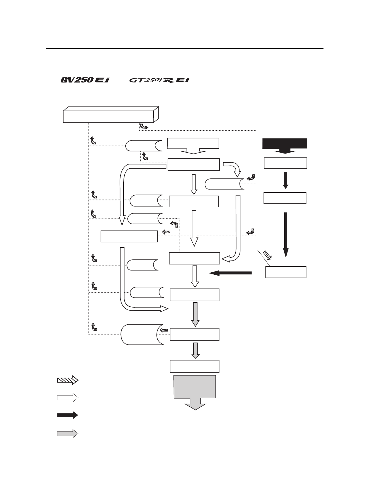
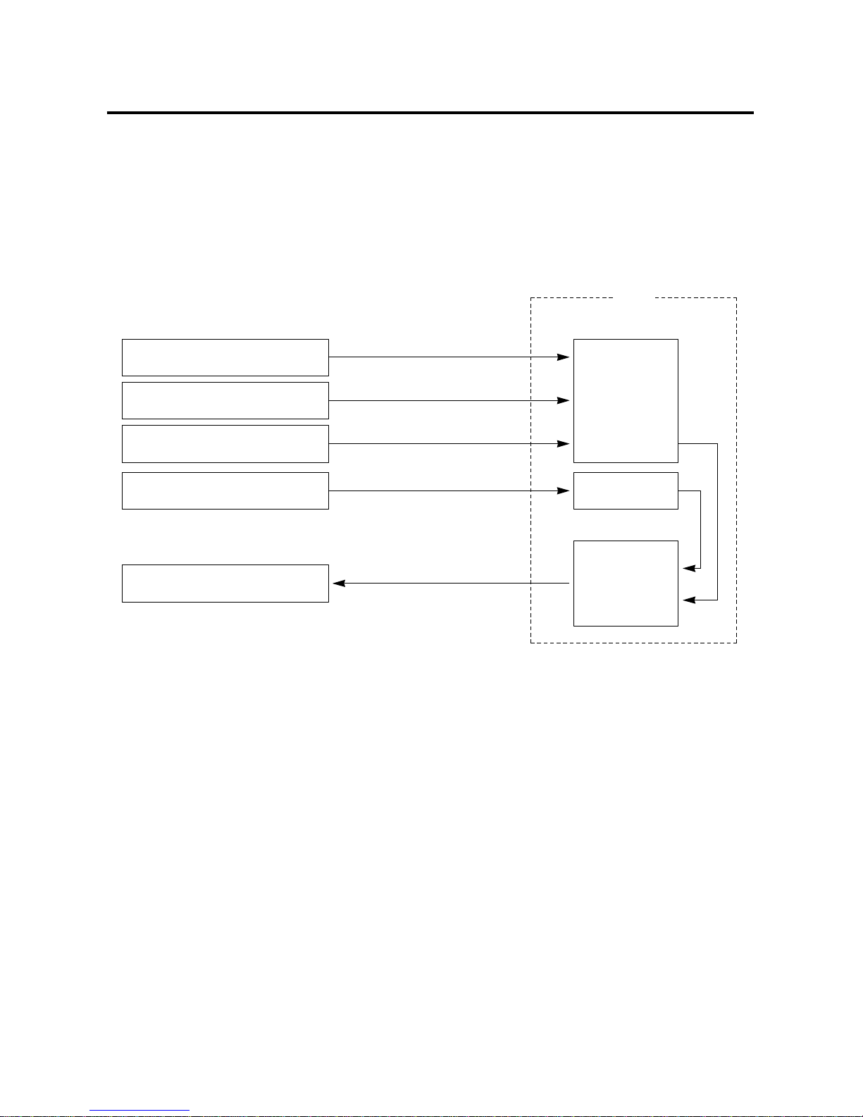
⊙⊙『『 』』& 『『 』』
EI SYSTEM’S CONTROL
DIAGRAM
ECU
IAT Sensor
TP Sensor
IAP Sensor
ISC Solenoid
AIR
AIR CLEANER
THROTTLE BODY
FUEL TANK
FUEL
FUEL PUMP
FUEL INJECTOR
INTAKE PIPE
CYLINDER
EXHAUST PIPE
O2 Sensor
: Electrical signal flow
: Air flow
: Fuel flow
: Exhaust gas flow
Pick-up Coil
ET Sensor
SAV Solenoid
MUFFLER
EXHAUST GAS
21
EI SYSTEM DIAGNOSIS 4-1-6
⊙⊙
INJECTION TIME (INJECTION VOLUME)
The factors to determine the injection time include the basic fuel injection time, which is calculated on the basis of
intake air pressure, engine speed and throttle opening angle, and various compensations.
These compensations are determined according to the signals from various sensors that detect the engine and
driving conditions.
Intake Air Pressure Sensor
(IAP Sensor)
Intake air pressure signal
Basic
fuel
injection
time
Compensation
Ultimate
fuel
injection
time
Pick-up coil
Throttle Position Sensor
(TP Sensor)
Various Sensors
Injectors
Engine speed signal
Throttle opening signal
Various signals
Injection signal
ECU
22
4-1-7 EI SYSTEM DIAGNOSIS
⊙⊙
COMPENSATION OF INJECTION TIME (VOLUME)
The following different signals are output from the respective sensors for compensation of the fuel injection time
(volume).
⊙⊙
INJECTION STOP CONTROL
SIGNAL DESCRIPTION
ENGINE TEMPERATURE
SENSOR SIGNAL
INTAKE AIR TEMPERATURE SENSOR
SIGNAL
BATTERY VOLTAGE SIGNAL
ENGINE RPM SIGNAL
STARTING SIGNAL
ACCELERATION SIGNAL /
DECELERATION SIGNAL
When engine temperature is low, injection time (volume) is
increased.
When intake air temperature is low, injection time (volume) is
increased.
ECU operates on the battery voltage and at the same time, it
monitors the voltage signal for compensation of the fuel injection
time (volume). A longer injection time is needed to adjust
injection volume in the case of low voltage.
At high speed, the injection time (volume) is increased.
When starting engine, additional fuel is injected during cranking
engine.
During acceleration, the fuel injection time (volume) is increased
in accordance with the throttle opening speed and engine rpm.
During deceleration, the fuel injection time (volume) is
decreased.
SIGNAL DESCRIPTION
ROLL OVER SWITCH SIGNAL
(FUEL CUT-OFF)
OVER-REV. LIMITER SIGNAL
When the motorcycle rolls over, the roll over switch sends a
signal to the ECU. Then, this signal cuts OFF current supplied to
the fuel pump, fuel injector and ignition coil.
The fuel injectors stop operation when engine rpm reaches rev.
limit rpm.
23
EI SYSTEM DIAGNOSIS 4-1-8
⊙⊙
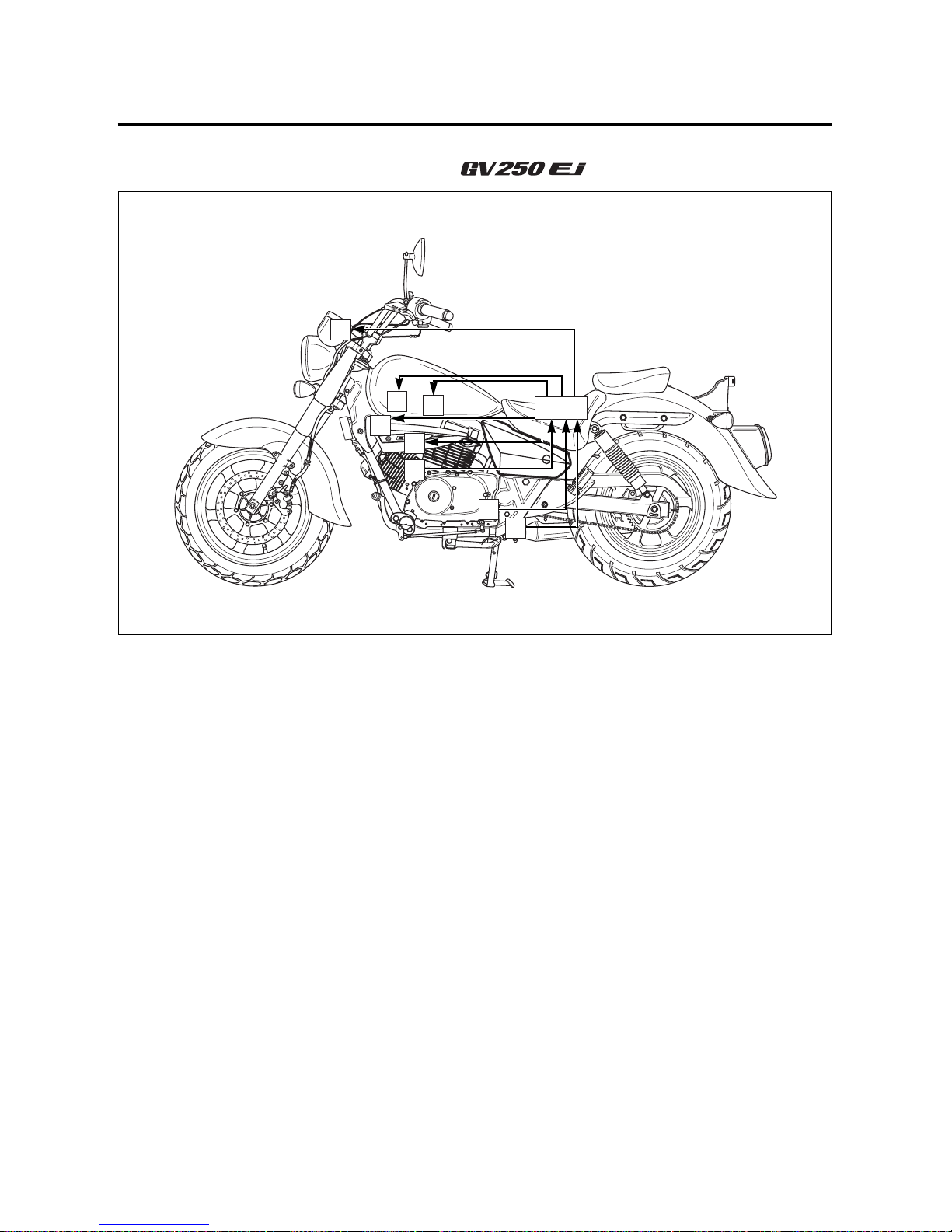
EI SYSTEM PARTS LOCATION
~~ ₩₩
① Speedometer
② Ignition coil, NO.1
③ Ignition coil, NO.2
④ Pick-up coil
⑤ GP switch
⑥ Fuel injector, NO.1
⑦ Fuel injector, NO.2
⑧ TP sensor
ECU
3
4
2
6
5
7
8
1
24
4-1-9 EI SYSTEM DIAGNOSIS
⑨ ISC solenoid
⑩ IAT sensor
⑪ RO switch
⑫ Fuel pump relay
⑬ IAP sensor, NO.2
⑭ IAP sensor, NO.1
⑮ ET sensor
⒃ Oxygen sensor
⒔ SAV solenoid
ECU
15
12
17
16
13
11
14
10
9
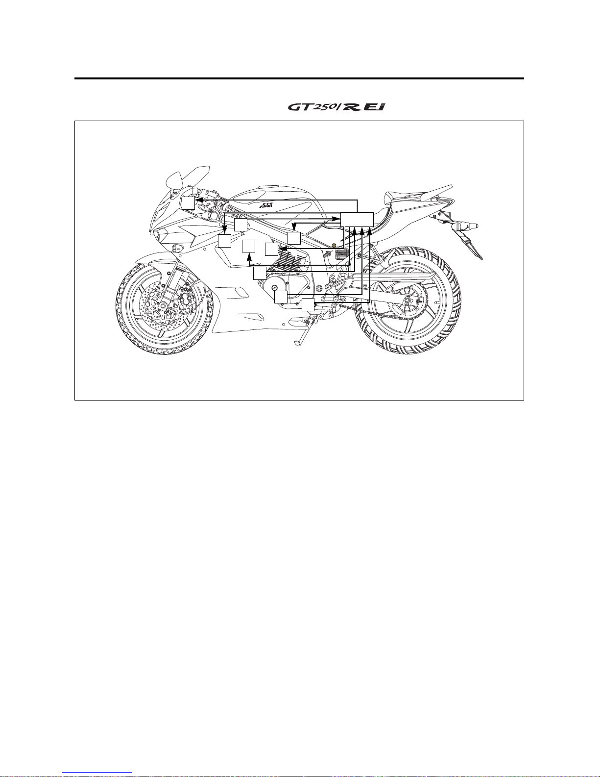
25
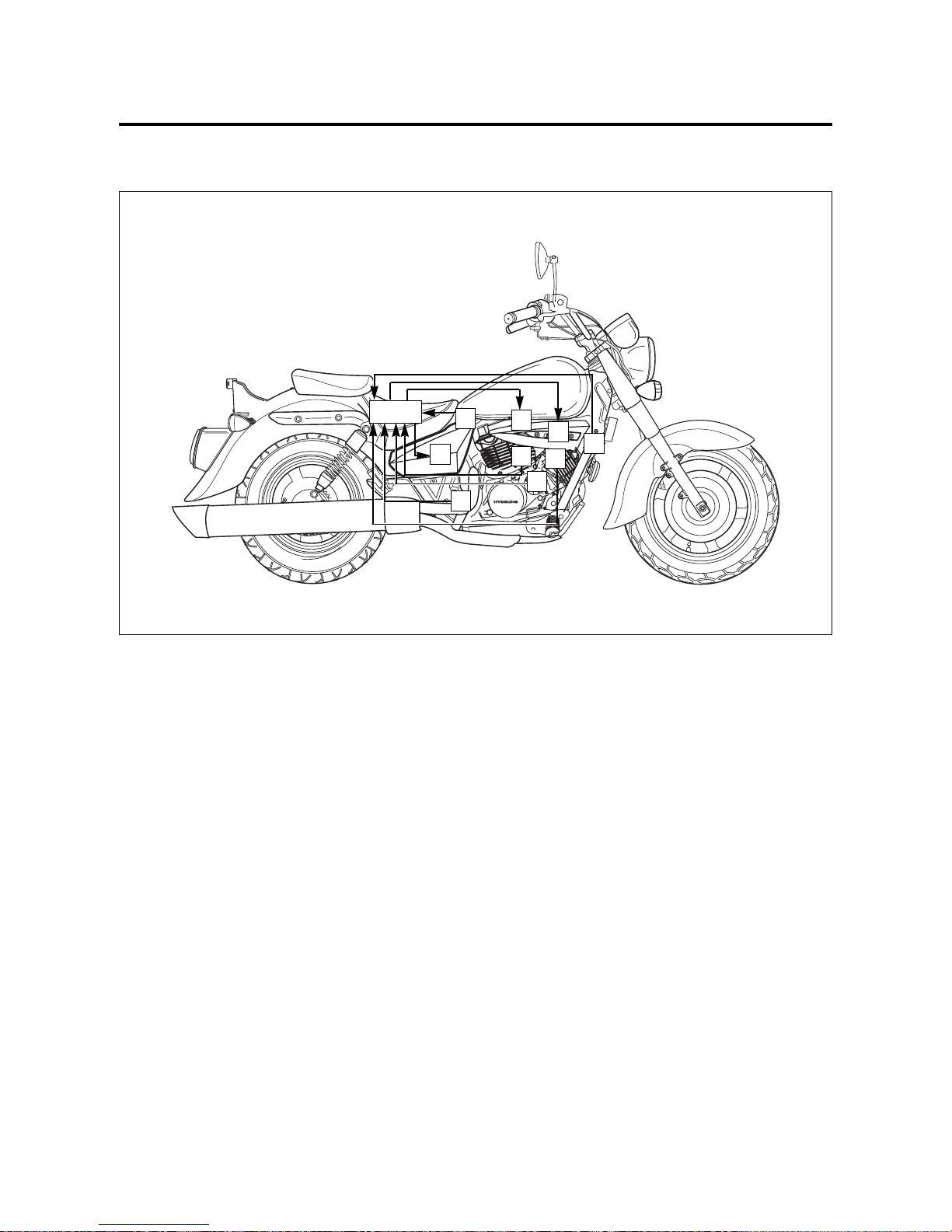
⊙⊙
EI SYSTEM PARTS LOCATION
~~ ₩₩
① Speedometer
② Fuel injector, NO.1
③ Fuel injector, NO.2
④ IAT sensor
⑤ GP switch
⑥ Pick-up coil
⑦ Ignition coil, NO.1
⑧ Ignition coil, NO.2
⑨ TP sensor
EI SYSTEM DIAGNOSIS 4-1-10
ECU
3
4
2
6
5
7
8
9
1
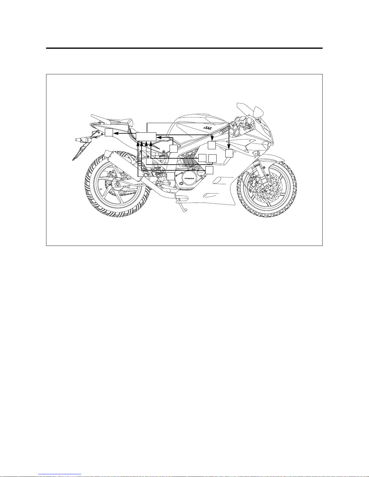
26
4-1-11 EI SYSTEM DIAGNOSIS
26
⑩ ISC solenoid
⑪ Fuel pump relay
⑫ RO switch
⑬ IAP sensor, NO.2
⑭ IAP sensor, NO.1
⑮ ET sensor
⒃ Oxygen sensor
⒔ SAV solenoid
10
17
11
12
16
13
14
15
ECU

27
EI SYSTEM DIAGNOSIS 4-1-12
SELF-DIAGNOSIS FUNCTION
~~ ₩₩
The self-diagnosis function is incorporated in the ECU.
The function has two modes, “USER MODE” and “DEALER MODE”.
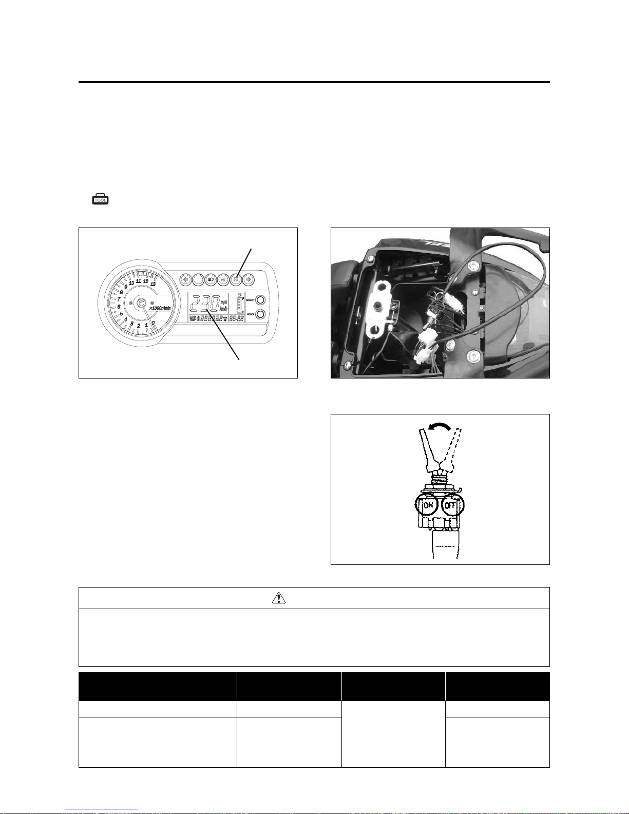
The user can only be notified by the LCD(DISPLAY) panel ① and the “FI” check lamp “ ” ②.
To check the function of the individual EI system devices, the dealer mode is prepared.
In this check, the special tool is necessary to read the code of the malfunction items.
A
When one of the signals is not received by ECU, the fail-safe circuit works and injection is not stopped.
In this case, “FI” letters and speedometer are indicated in the LCD panel ① and motorcycle can run.
B
The injection signal is stopped, when the pick-up coil signal, roll over switch signal, NO.1 & NO.2 ignition signals,
NO.1 & NO.2 injector signals, fuel pump relay signal or ignition switch signal is not sent to ECU.
In this case, “FI” letters is indicated in the LCD panel ①. Motorcycle does not run.
“CHE” : The LCD panel ① indicates “CHE” letters when no communication signal from the ECU is received for 3
seconds.
For example, The ignition switch is turned “ON” position, and the engine stop switch is turned “ ” position.
In this case, the speedometer does not receive any signal from ECU, and the LCD panel ① indicates “CHE”
letters.
If “CHE” letters is indicated, the LCD panel ① does not indicate the trouble code.
The possible cause of this indication is as follows, Engine stop switch is in “ ” position. Ignition fuse is burnt.
It is necessary to check the wiring harness between ECU and speedometer couplers.
⊙⊙
USER MODE
MALFUNCTION
“NO”
“YES”
“FI” check lamp
comes on.
Each 2 sec.
Speedometer or “FI”
letters is indicated.
Speedometer
--
Speedometer
and
“FI” letters
A
“FI” letters
B
Engine can start
Engine can not
start
“FI” check lamp comes
on and blinks.
“FI” letters is indicated
continuously.
LCD (DISPLAY)
INDICATION
①①
INDICATION
MODE
“FI”
CHECK LAMP
INDICATION
②②
①
②
The “FI” check lamp “ ” ② comes on for about three seconds whenever the ignition switch is set to “ON”
position with the engine stopped as a test of the injection system operation.
The check lamp must go off after three seconds.
28
4-1-13 EI SYSTEM DIAGNOSIS
CAUTION
Do not disconnect the ECU lead wire couplers, before checking the malfunction code, or the malfunction
code memory is erased and the malfunction code can not be checked.
Confirm the malfunction code after turn the ignition switch “ON” position or cranking the engine for few
seconds.
Mode select switch : 09900-27000
⊙⊙
DEALER MODE
The defective function is memorized in the ECU.
Use the special tool’s coupler to connect to the dealer mode coupler. (Refer to page 4-1-20)
The memorized malfunction code is displayed on LCD (DISPLAY) panel .
Malfunction means that the ECU does not receive signal from the devices.
These affected devices are indicated in the code form.
MALFUNCTION
“NO”
“YES”
“FI” check lamp
goes off.
For each 2 sec.,
code is indicated.
C
-
C**code is indicated
from small numeral to
large one.
LCD (DISPLAY)
INDICATION
INDICATION
MODE
“FI”
CHECK LAMP
INDICATION
29
EI SYSTEM DIAGNOSIS 4-1-14
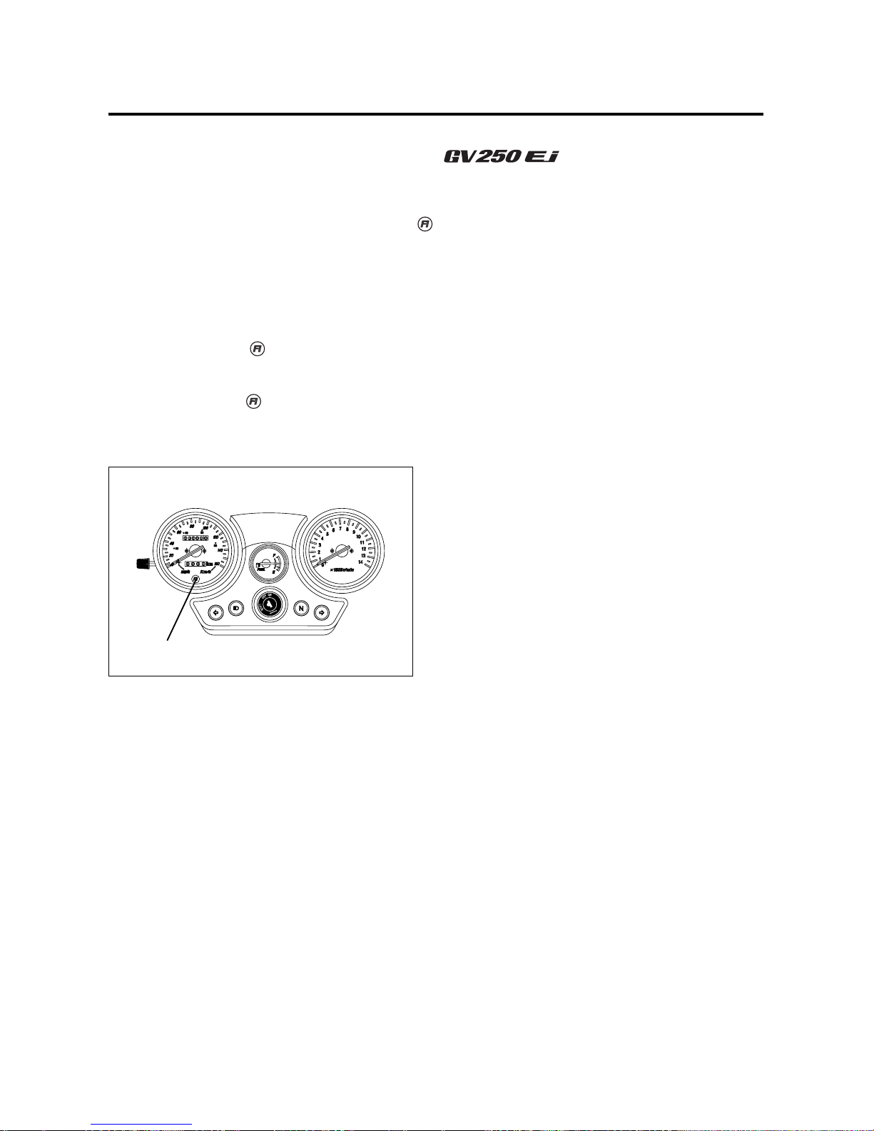
SELF-DIAGNOSIS FUNCTION
~~ ₩₩
The self-diagnosis function is incorporated in the ECU.
The function has two modes, “USER MODE” and “DEALER MODE”.
The user can only be notified by the “FI” check lamp “ ” ①.
To check the function of the individual EI system devices, the dealer mode is prepared.
In this check, the special tool is necessary to read the code of the malfunction items.
⊙⊙
USER MODE
The “FI” check lamp “ ” ① comes on for about three seconds whenever the ignition switch is set to “ON”
position with the engine stopped as a test of the injection system operation.
The check lamp must go off after three seconds.
If the “FI” check lamp “ ” ① comes on during normal engine operation, it means that the electric fuel injection
system is not operating correctly.
When this is the case, inspect the electric fuel injection system to refer to “Dealer mode”.
①
 Loading...