

HYOSUNG 2010 ST7 Service Manual

Servicemanual
ST7
GV700C
2010 -
Holtvej 8-10, Høruphav
6470 Sydals
Telefon: +45 73 15 11 00
Fax: +45 73 15 11 01
E-mail: info@scanmi.dk
www.scanmi.dk
CVR: 27 73 31 07

COPYRIGHT S&T Motors Co., Ltd.
ELECTRICAL SYSTEM
COOLING SYSTEM
GROUP INDEX
GENERAL INFORMATION
1
PERIODIC MAINTENANCE
2
ENGINE
3
EI SYSTEM DIAGNOSIS
4
FUEL SYSTEM AND THROTTLE BODY
5
6
7
CHASSIS
8
SERVICING INFORMATION
9
FOREWORD
This manual contains an introductory description on
HYOSUNG and procedures for its inspection/service and overhaul of its main components.
Other information considered as generally known is
not included.
Read GENERAL INFORMATION section to familiarize yourself with outline of the vehicle and MAINTENANCE and other sections to use as a guide for
proper inspection and service.
This manual will help you know the vehicle better so
that you can assure your customers of your optimum
and quick service.
This manual has been prepared on the basis of
the latest specification at the time of publica-
tion.
If modification has been made since then,
difference may exist between the content of
this manual and the actual vehicle.
Illustrations in this manual are used to show
the basic principles of operation and work pro-
cedures.
They may not represent the actual vehicle
exactly in detail.
WARNING
This manual is intended for those who have
enough knowledge and skills for servicing
HYOSUNG vehicles. Without such knowledge and
skills, you should not attempt servicing by relying
on this manual only.
Instead, please contact your nearby authorized
HYOSUNG motorcycle dealer.
HOW TO USE THIS MANUAL
TO LOCATE WHAT YOU ARE
LOOKING FOR :
1. The text of this manual is divided into sections.
2. As the title of these sections is listed on the previous
page as GROUP INDEX, select the section where you are
looking for.
3. Holding the manual as shown at the right will allow you to
find the first page of the section easily.
4. On the first page of each section, its contents are listed.
Find the item and page you need.
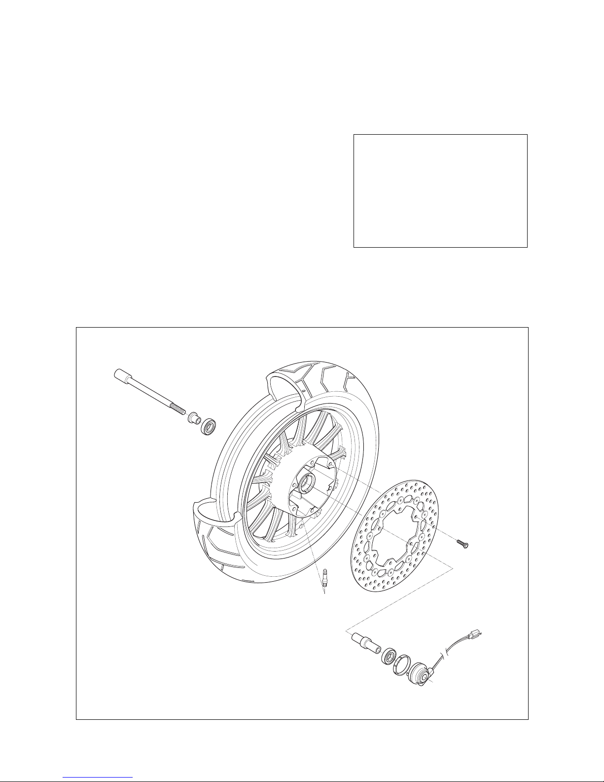
COMPONENT PARTS
Example : Front wheel

SYMBOL
Listed in the table below are the symbols indicating instructions and other information necessary for servicing.
The meaning of each symbol is also included in the table.
Apply THREAD LOCK 1324 .
Apply or use brake fluid.
Measure in voltage range.
Measure in resistance range.
Measure in current range.
Measure in diode test range.
Measure in continuity test range.
Use special tool.
Use engine coolant.
Torque control required.
Data beside it indicates specified torque.
Apply oil. Use engine oil unless otherwise
specified.
Apply SUPER GREASE
A .
Apply SILICONE GREASE.
Apply MOLY PASTE.
Apply BOND
1215 .
Use fork oil.
DEFINITIONSYMBOL DEFINITIONSYMBOL
Apply SUPER GREASE C .

NOTE
Difference between photographs and actual motorcycles depends on the markets.

A
ABDC : After Bottom Dead Center
AC : Alternating Current
API : American Petroleum Institute
ATDC : After Top Dead Center
B
BBDC : Before Bottom Dead Center
BDC : Bettom Dead Center
BTDC : Before Top Dead Center
D
DC : Direct Current
DOHC : Double Over Head Camshaft
E
ECU : Engine Control Unit,
EI Control Unit
EI : Electric fuel Injection,
Electric fuel Injector
F
FP : Fuel Pump
G
GP Switch : Gear Position Switch
I
IAP Sensor : Intake Air Pressure Sensor
(IAPS)
IAT Sensor : Intake Air Temperature Sensor
(IATS)
IG : Ignition
ISC Solenoid : Idle Speed Control Solenoid
L
LCD : Liquid Crystal Display
LED : Light Emitting Diode
LH : Left Hand
M
Max : Maximum
Min : Minimum
O
O2 Sensor : Oxygen Sensor (O2S)
P
PV : Purge control Valve
R
RH : Right Hand
RO Switch : Roll Over Switch
S
SAE :
Society of Automotive Engineers
SAV Solenoid : Secondary Air Valve Solenoid
T
TDC : Top Dead Center
TP Sensor : Throttle Position Sensor (TPS)
W
WT Sensor : Water Temperature Sensor
(WTS)
ABBREVIATIONS USED IN THIS MANUAL

BL : Black with Blue tracer BBr : Black with Brown tracer
BG : Black with Green tracer BO : Black with Orange tracer
BR : Black with Red tracer BW : Black with White tracer
BY : Black with Yellow tracer LB : Blue with Black tracer
LG : Blue with Green tracer LR : Blue with Red tracer
LW : Blue with White tracer LY : Blue with Yellow tracer
BrB : Brown with Black tracer BrW : Brown with White tracer
GB : Green with Black tracer GR : Green with Red tracer
GY : Green with Yellow tracer GrB : Gray with Black tracer
GrR : Gray with Red tracer GrW : Gray with White tracer
OB : Orange with Black tracer OL : Orange with Blue tracer
OG : Orange with Green tracer OR : Orange with Red tracer
OW : Orange with White tracer OY : Orange with Yellow tracer
RB : Red with Black tracer RW : Red with White tracer
WB : White with Black tracer WL : White with Blue tracer
WR : White with Red tracer YB : Yellow with Black tracer
YL : Yellow with Blue tracer YG : Yellow with Green tracer
YR : Yellow with Red tracer
B : Black Gr : Gray Sb : Light blue
L : Blue Lg : Light green W : White
Br : Brown O : Orange Y : Yellow
G : Green R : Red
WIRE COLOR

GENERAL INFORMATION
INFORMATION LABELS 1
-
1
GENERAL PRECAUTIONS 1
-
1
SERIAL NUMBER LOCATION 1
-
3
FUEL, OIL AND ENGINE COOLANT RECOMMENDATIONS
1- 4
BREAK-IN PROCEDURES 1
-
6
CYLINDER CLASSIFICATION 1
-
6
EXTERIOR ILLUSTRATION 1
-
7
SPECIFICATIONS 1
-
8
CONTENTS
1

1-1 GENERAL INFORMATION
Please note, however, that the warning and cautions contained in this manual cannot possibly cover all potential
hazards relating to the servicing, or lack of servicing, of the motorcycle. In addition to the WARNING and CAUTION
stated, you must use good judgement and basic mechanical safety principles. If you are unsure about how to perform a particular service operation, ask a more experienced mechanic for advice.
WARNING / CAUTION / NOTE
Please read this manual and follow its instructions carefully.
To emphasize special information, the symbol and the words WARNING, CAUTION and NOTE have special meanings. Pay special attention to the messages highlighted by these signal words.
CAUTION
Indicates a potential hazard that could result in vehicle damage.
WARNING
Indicates a potential hazard that could result in death or injury.
NOTE
Indicates special information to make maintenance easier or instructions cleaner.

GENERAL INFORMATION 1-2
GENERAL PRECAUTIONS
WARNING
Proper service and repair procedures are important for the safety of the service machanic and the safety
and reliability of the vehicle.
When 2 or more persons work together, pay attention to the safety of each other.
When it is necessary to run the engine indoors, make sure that exhaust gas is forced outdoors.
When working with toxic or flammable materials, make sure that the area you work in is well-ventilated and
that you follow all off the material manufacturer’s instructions.
Never use gasoline as a cleaning solvent.
To avoid getting burned, do not touch the engine, engine oil, exhaust system or radiator during or for a
while after engine operation.
After servicing fuel, oil, engine coolant, exhaust or brake systems, check all lines and fittings related to the
system for leaks.
WARNING
If parts replacement is necessary, replace the parts with HYOSUNG Genuine Parts or their equivalent.
When removing parts that are to be reused, keep them arranged in an orderly manner so that they may be
reinstalled in the proper order and orientation.
Be sure to use special tools when instructed.
Make sure that all parts used in reassembly are clean, and also lubricated when specified.
When use of a certain type of lubricant, bond, or sealant is specified, be sure to use the specified type.
When removing the battery, disconnect the battery lead wire first and then the battery lead wire.
When reconnecting the battery, connect the battery lead wire first and then the battery lead wire.
Finally, cover the battery terminal with the terminal cover.
When performing service to electrical parts, if the service procedures do not require use of battery power,
diconnect the battery lead wire at the battery.
Tighten cylinder head and case bolts and nuts, beginning with larger diameter and ending with smaller
diameter, from inside to outside diagonally, to the specified tightening torque.
Whenever you remove oil seals, gaskets, packing, O-rings, locking washers, cotter pins, circlips, and certain other parts as specified, be sure to replace them with new ones. Also, before installing these new
parts, be sure to remove any material left over from the mating surfaces.
Never reuse a circlip. When installing a new circlip, take care not to expand the end gap larger than
required to slip the circlip over the shaft. After installing a circlip, always ensure that it is completely seated in its groove and securely fitted.
Do not use self-locking nuts a few times over.
Use a torque wrench to tighten fasteners to the torque values when specified. Wipe off grease or oil if a
thread is smeared with them.
After reassembly, check parts for tightness and operation.
WARNING
To protect environment, do not unlawfully dispose of used engine oil and other fluids: batteries, and tires.
To protect Earth’s natural resouces, properly dispose of used vehicles and parts.
FRAME SERIAL NUMBER
ENGINE SERIAL NUMBER
1-3 GENERAL INFORMATION
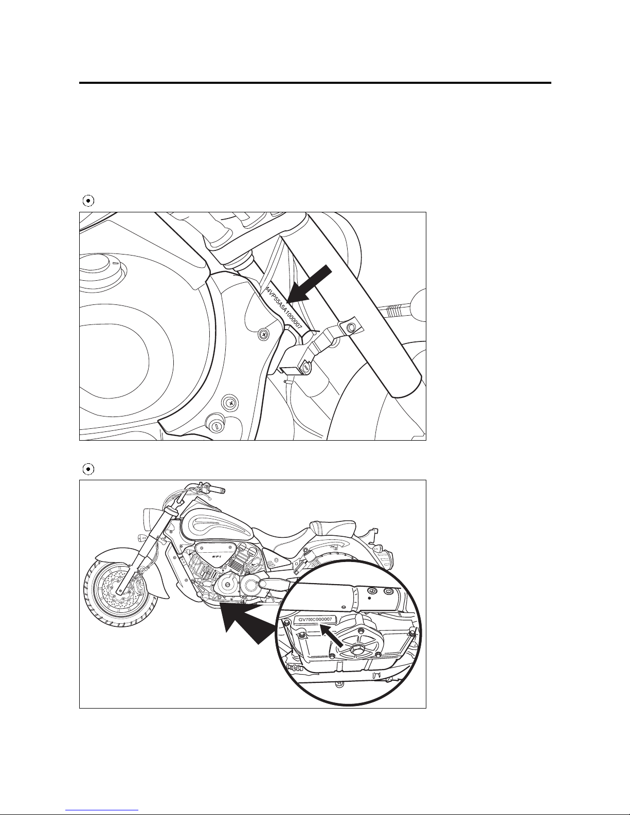
SERIAL NUMBER LOCATION
The frame serial number or V.I.N. (Vehicle Identification Number) is stamped on the right side of the steering head tube.
The engine serial number is stamped on the left downside of the crankcase assembly.
These numbers are required especially for registering the machine and ordering spare parts.
BRAKE FLUID
Specification and classification : DOT4
If an SAE 10W/40 motor oil is not available, select an
alternative according to the following chart.
Use a premium quality 4-stroke motor oil to ensure
longer service life of your motorcycle.
FUEL, OIL AND ENGINE COOLANT RECOMMENDATIONS
FUEL
Gasoline used should be graded 91 octane (Research Method) or higher. An unleaded gasoline type is
recommended.
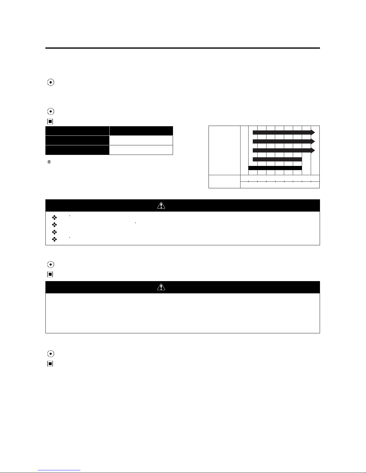
ENGINE OIL
ENGINE OIL SPECIFICATION
GENERAL INFORMATION 1-4
Classification system
API
SAE
Grade
Over SL
10W/40
ENGINE OIL
Temperature
℃
℉
-30
-22
-20-4-101403210502068308640
104
20W50
15W40 15W50
10W40 10W50
10W30
5W30
FRONT FORK OIL
Use fork oil : TELLUS #32
WARNING
Don t mix the unrecommended oil. It could damage the engine.
When refilling the oil tank, don t allow the dust to get inside.
Wipe the spilled oil up immediately.
Don t put the patch on the cap. It could disturb the oil to be provided and damage the engine.
WARNING
Since the brake system of this motorcycle is filled with a glycol-based brake fluid by the manufacturer, do
not use or mix different types of fluid such as silicone-based and petroleum-based fluid for refilling the
system, otherwise serious damage will result.
Do not use any brake fluid taken from old or used or unsealed containers.
Never re-use brake fluid left over from a previous servicing, which has been stored for a long period.

1-5 GENERAL INFORMATION
ENGINE COOLANT
Use an anti-freeze/engine coolant compatible with an aluminum radiator, mixed with distilled water only.
WATER FOR MIXING
Use distilled water only. Water other than distilled water can corrode and clog the aluminum radiator.
ANTI-FREEZE/ENGINE COOLANT
The engine coolant perform as a corrosion and rust inhibitor as well as anti-freeze. Therefore, the engine coolant
should be used at all times even though the atmospheric temperature in your area does not go down to freezing point.
Hyosung recommends the use of HYOSUNG COOLANT anti-freeze/engine coolant. If this is not available, use an
equivalent which is compatible with an aluminum radiator.
LIQUID AMOUNT OF WATER/ENGINE COOLANT
For engine coolant mixture information, refer to cooling system section, page 6-1
CAUTION
Mixture of anti-freeze/engine coolant should be limited to 60%. Mixing beyond it would reduce its efficiency.
If the anti-freeze/engine coolant mixing ratio is below 50%, rust inhabiting performance is greatly reduced.
Be sure to mix it above 50% even though the atmospheric temperature does not go down to the freezing
point.
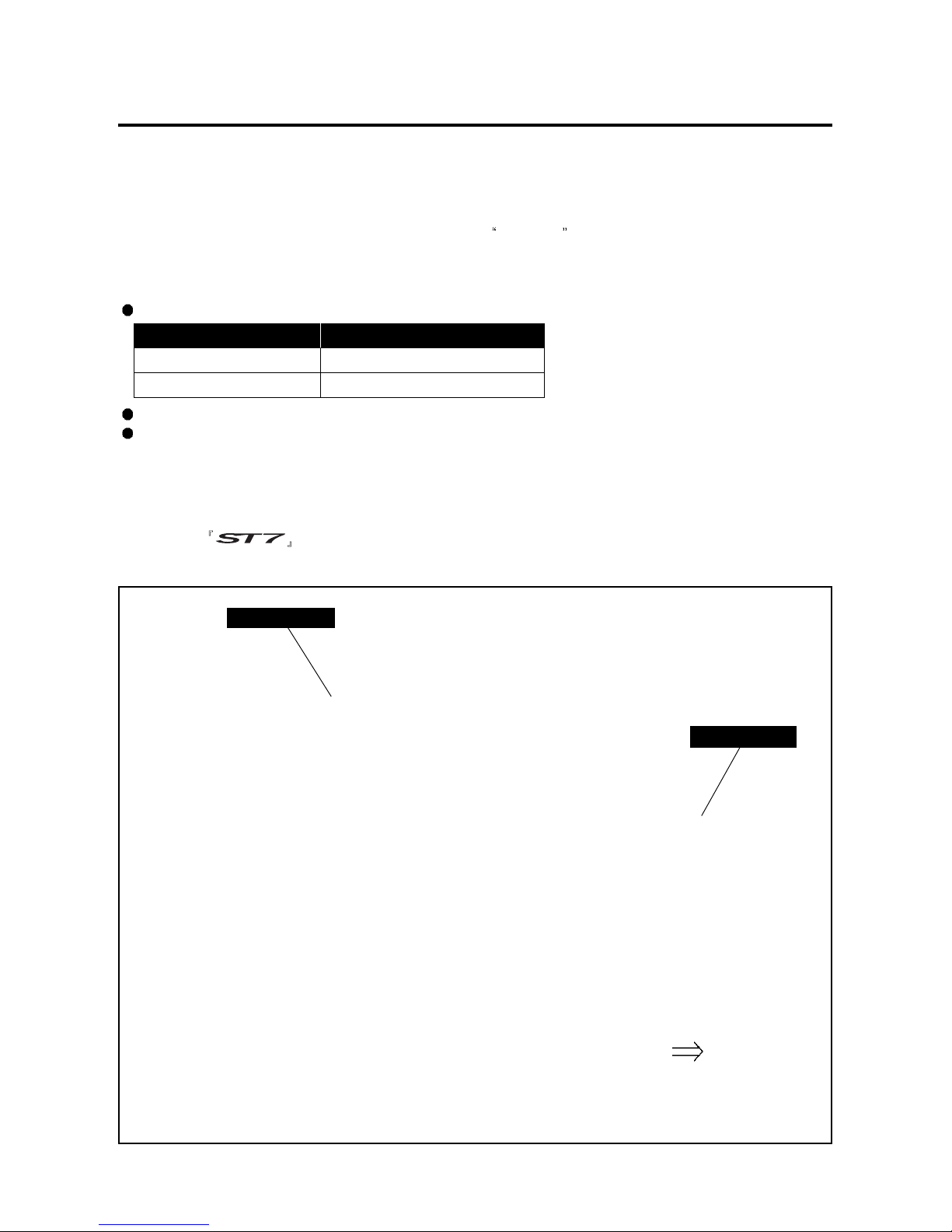
CYLINDER CLASSIFICATION
The engine of is composed of the two cylinder, is classified into the front cylinder and rear cylinder
as basis of the motorcycle ahead.
Upon reaching an odometer reading of 1,600 km (1,000 miles) you can subject the motorcycle to full throttle operation.
Do not maintain constant engine speed for an extended period during any portion of the break-in.
Try to vary the throttle position.
BREAK-IN PROCEDURES
During manufacture only the best possible materials are used and all machined parts are finished to a very high
standard but it is still necessary to allow the moving parts to BREAK-IN before subjecting the engine to maximum
stresses.
The future performance and reliability of the engine depends on the care and restraint exercised during its early life.
The general rules are as follows :
Keep to these break-in procedures :
FRONT
GENERAL INFORMATION 1-6
Interval Maximum throttle opening
Less than 1/2 throttle
Initial 800 km (500 miles)
Less than 3/4 throttle
Up to 1,600 km (1,000 miles)
Rear cylinder
Front cylinder
1-7 GENERAL INFORMATION
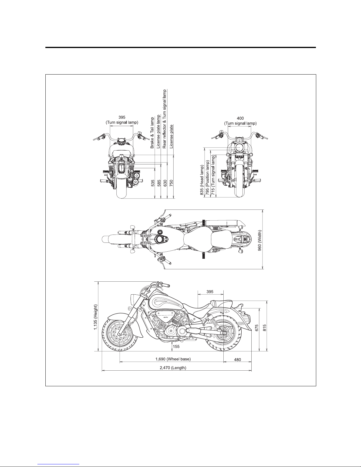
EXTERIOR ILLUSTRATION
Unit : mm
2,470 mm (97.2 in)
960 mm (37.8 in)
1,135 mm (44.7 in)
1,690 mm (66.5 in)
155 mm (6.1 in)
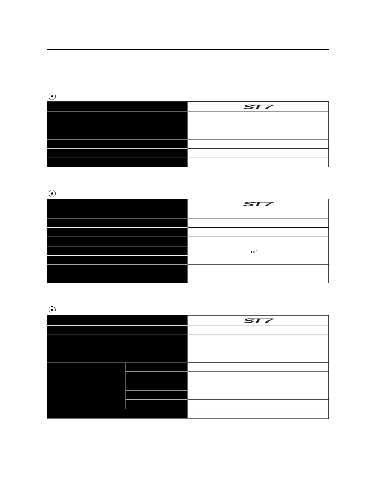
244 kg (538 lbs)
Overall length
Overall width
Overall height
Wheelbase
Ground clearance
Mass of vehicle in running order
ITEM
ITEM
ITEM
Four-stroke, DOHC, Liquid-cooled
V-2 cylinder
81.5 mm (3.21 in)
65.0 mm (2.56 in)
678.2 (41.4 in3)
Electric fuel injection
Electric starter
Wet sump
Type
Number of cylinder
Bore
Stroke
Piston displacement
Fuel system
Starter system
Lubrication system
Wet multi-plate type
5-speed constant mesh
1-down, 4-up
2.69
2.46
1.78
1.38
1.13
0.96
Poly chain belt
Gear ratio
Clutch
Transmission
Gearshift pattern
Final reduction
Drive belt
1st
2nd
3rd
4th
5th
GENERAL INFORMATION 1-8
SPECIFICATIONS
DIMENSIONS AND DRY MASS
ENGINE
TRANSMISSION
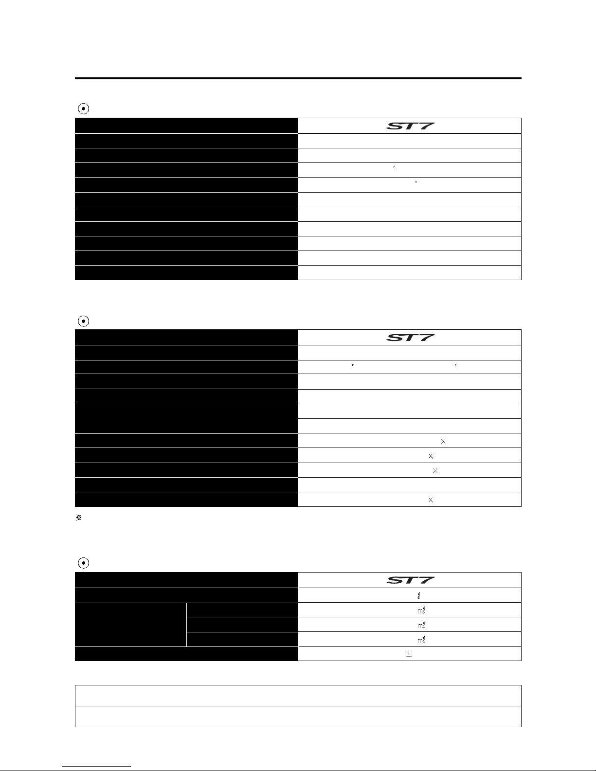
Telescopic type
Swingarm type
38 (right & left)
33
142 mm (5.6 in)
Disk brake
Disk brake
120/80 - 16 60H
170/80 - 15 77H
130 mm (5.12 in)
Front suspension
Rear suspension
Steering angle
Caster
Trail
Front brake
Rear brake
Front tire size
Rear tire size
Front fork stroke
ITEM
ITEM
ITEM
ECU
BTDC 5 / 1,600 rpm and BTDC 35 / 7,000 rpm
CR8E
12V 12Ah (MF)
Main : 30 A
ECU : 15 A
12 V - H4 : 60/55 W 1
12 V - W5 W 1
12 V - RY10 W 4
LED type
12 V - W5 W 1
Ignition type
Ignition timing
Spark plug
Battery
Head lamp
Position lamp
Turn signal lamp
Brake / Tail lamp
License plate lamp
LED : Light Emitting Diode
Fuel tank
Front fork oil capacity (One side)
Engine oil capacity
17.0
3,000
3,200
3,400
370 4 cc
1-9 GENERAL INFORMATION
CHASSIS
ELECTRICAL
CAPACITIES
Fuse
NOTE
The specifications are subject to change without notice.
Oil change
Oil and filter change
Engine overhaul

PERIODIC MAINTENANCE SCHEDULE 2
-
1
PERIODIC MAINTENANCE CHART 2-1
LUBRICATION POINTS 2-2
MAINTENANCE PROCEDURES 2
-
3
VALVE CLEARANCE 2-3
SPARK PLUG 2-5
EXHAUST PIPE BOLTS AND MUFFLER MOUNTING BOLTS 2-7
AIR CLEANER 2-7
ENGINE IDLE SPEED 2-9
THROTTLE CABLE PLAY 2-9
FUEL HOSE 2-10
CLUTCH 2-10
ENGINE OIL 2-12
ENGINE OIL FILTER 2-14
DRIVE BELT 2-15
BRAKE SYSTEM 2-17
STEERING 2-22
FRONT FORK
2-22
REAR SUSPENSION
2-22
TIRE 2-23
CHASSIS BOLTS AND NUTS
2-23
ENGINE COOLANT
2-24
RADIATOR HOSE
2-26
COMPRESSION PRESSURE 2-27
OIL PRESSURE
2-28
CONTENTS
2
PERIODIC MAINTENANCE
2-1 PERIODIC MAINTENANCE
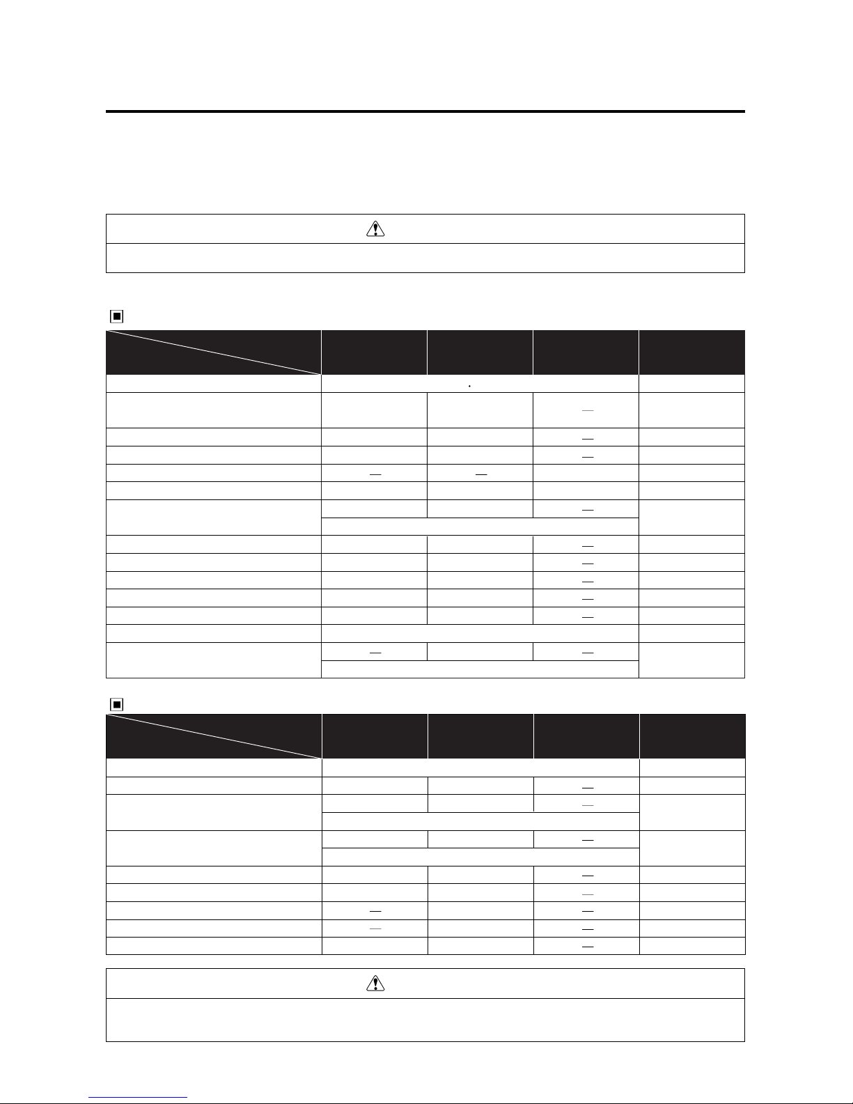
Item
Initial 1,000 km Every 6,000 km
Every 12,000 km
page
Interval
Air cleaner element
Exhaust pipe bolts and
muffler mounting bolts
Valve clearance adjust
Cylinder head bolt
Cylinder head & Cylinder
Spark plug
Fuel hose
Engine oil filter
Engine oil
Throttle cable
Idle speed
Clutch
Engine coolant
Radiator hoses
Tighten
Inspect
Tighten
Clean
Inspect
Replace
Replace
Inspect
Inspect
Inspect
Remove carbon
Replace
Replace every 4 years
Replace every 2 years
Replace every 4 years
Item
Initial 1,000 km Every 6,000 km
Every 12,000 km
page
Interval
Drive belt
Brake
Brake hoses
Brake fluid
Tires
Steering
Front forks
Rear suspension
Chassis bolts and nuts
Inspect
Inspect
Inspect
Inspect
Inspect
Tighten
Inspect
Inspect
Inspect
Inspect
Inspect
Inspect
Inspect
Tighten
Inspect every 1,000km
Replace every 4 years
Replace every 2 years
CHASSIS
2-15
2-17
2-17
2-17
2-23
2-22
2-22
2-22
2-23
PERIODIC MAINTENANCE SCHEDULE
The chart below lists the recommended intervals for all the required periodic service work necessary to keep the
motorcycle operating at peak performance and economy.
Tighten
Inspect
Tighten
Clean
Inspect
Replace
Replace
Inspect
Inspect
Inspect
Inspect
Clean every 3,000 km Replace every 12,000 km
PERIODIC MAINTENANCE CHART
ENGINE
2-7
2-7
2-3
3-52
3-23
2-5
2-10
2-14
2-12
2-9
2-9
2-10
2-24
2-26
CAUTION
More frequent servicing should be performed on motorcycles that are used under severe conditions.
CAUTION
Using poor quality replacement parts can cause your motorcycle to wear more quickly and shorten its useful life.
Use only genuine Hyoung replacement parts or their equivalent.
PERIODIC MAINTENANCE 2-2
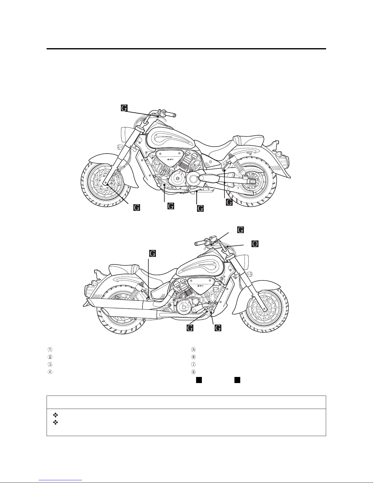
LUBRICATION POINTS
Proper lubrication is important for smooth operation and long life of each working part of the motorcycle.
Major lubrication points are indicated below.
Clutch lever holder and clutch cable
Passenger footrests pivot
Side stand pivot and spring hook
Footrests pivot
Speedo sensor
Front brake lever holder
Throttle cable
Rear brake pedal pivot
O - Motor oil, G - Grease
❶
❺
❷
❸
❹
❷
❻
❼
❽
❹
NOTE
Before lubricating each part, clean off any rusty spots and wipe off any grease, oil, dirt or grime.
Lubricate exposed parts which are subject to rust, with either engine oil or grease whenever the
motorcycle has been operated under wet or rainy condition.
2-3 PERIODIC MAINTENANCE
MAINTENANCE PROCEDURES
This section describes the service procedures for
each item mentioned in the Periodic Maintenance chart.
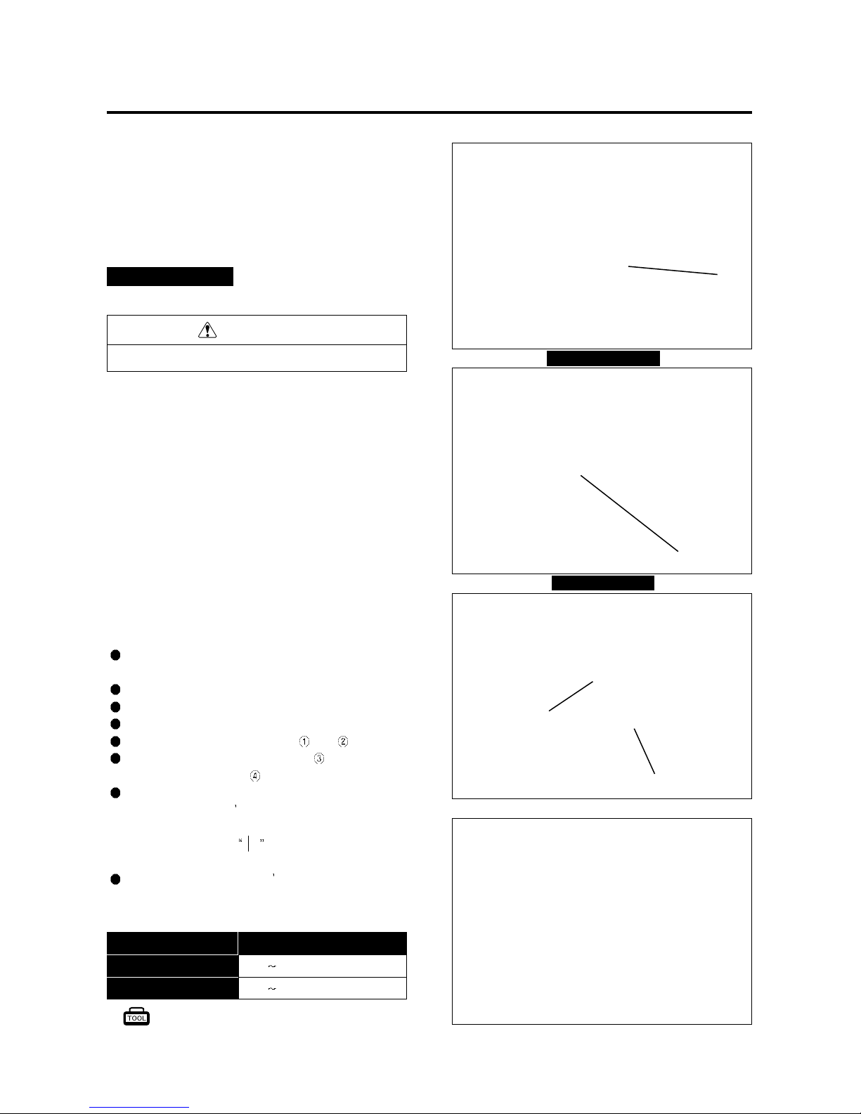
VALVE CLEARANCE
Excessive valve clearance results in valve noise and
insufficient valve clearance results in valve damage and
reduce power.
Check the intake and exhaust valve clearances at the
distances indicated above and adjust the valve clearances to specification, if necessary.
The valve clearance specification is different for
intake and exhaust valves.
Valve clearance adjustment must be checked and
adjusted :
1) at the time of periodic inspection,
2) when the valve mechanism is serviced, and
3) when the camshafts are removed.
Remove the radiator cover and radiator.
(Refer to page 2-5)
Remove the right air cleaner box.
Remove the seat and fuel tank. (Refer to page 5-2)
Remove the spark plugs. (Refer to page 2-5)
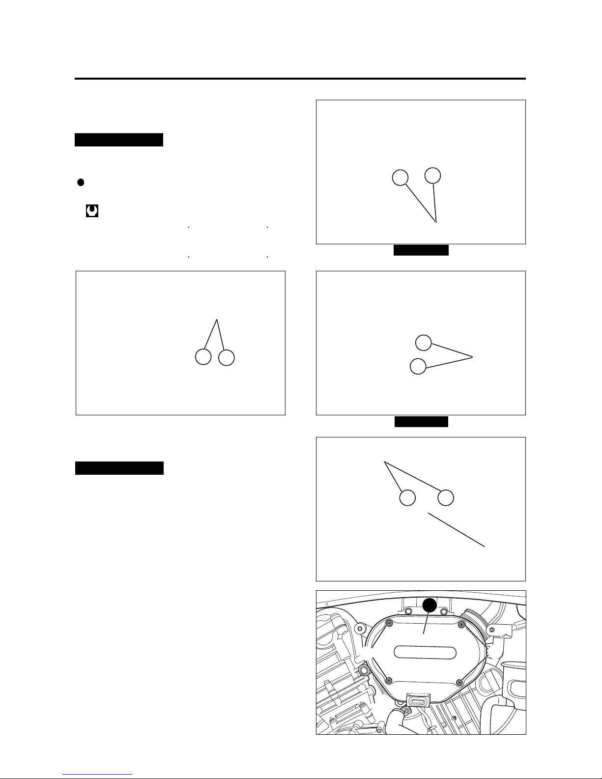
Remove the cylinder head cover and .
Remove the magneto cover plug and the valve
timing inspection plug
.
Rotate the magneto rotor counter-clockwise to set
the front cylinder
s piston at TDC (Top Dead
Center) of the compression stroke.
(Rotate the rotor until
F line on the rotor is aligned
with the center of hole on the crankcase.)
To inspect the front cylinder s valve clearance, insert
the thickness gauge to the clearance between the
camshaft and the tappet.
0.1 0.2 mm (0.004 ~ 0.008 in)
0.28
0.32 mm (0.011 ~ 0.013 in)
IN.
EX.
Standard (When cold)
Valve clearance
Inspect Interval
Inspect Initial 1,000 km and Every 6,000 km thereafter.
CAUTION
The clearance specification is for COLD state.
FRONT CYLINDER
REAR CYLINDER
Thickness gauge : 09900-20806
①
②
③
④

PERIODIC MAINTENANCE 2-4
If the clearance is out of specification, first remove the
cam chain tensioner, camshaft housing, camshaft.
To install the tappet shim at original position, record
the shim NO. and clearance to present by A , B ,
C , D mark on the cylinder head.
Select the tappet that agree with tappet clearance
(vertical line) and shim NO.(horizontal line) as refer to the
tappet shim selection chart. (Refer to page 9-39 40)
Adjust valve timing, install the camshaft housing and
the tension adjuster.
After the crankshaft rotate about 10 times, measure
the valve clearance.
If the clearance be not correct, adjust the standard
clearance as the same manner above.
In case of valve adjustment which is not the tappet
shim selection chart, please follow instructions of
example in the below.
For example, the intake clearance is 0.4 and the shim
is 170 (1.70 mm), select 195 (1.95 mm) of the shim
which 170 (1.70 mm) of the shim add up the excess
clearance 0.25 mm when adjust with the standard
0.15 as the intake standard clearance 0.1 0.2 mm.
Rotate the magneto rotor to set the rear cylinder s
piston at TDC(Top Dead Center) of the compression
stroke.
(Rotate the rotor 285 counter-clockwise from the
F line, and until the R line on the rotor is
aligned with the center of hole on the crankcase.)
Inspect the rear cylinder s valve clearance with the
same manner of the front cylinder.
CAUTION
Valve clearance should be checked when the
engine is cold.
If you don t rotate the crankshaft about 10
times before measuring the valve clearance,
there is no meaning of valve clearance.
A B
C D
2-5 PERIODIC MAINTENANCE
TYPE SPARK PLUG SPECIFICATION
CR7E
CR8E
CR9E
Hot type
Standard type
Cold type
Remove the four radiator mounting bolts.
Remove the four radiator cover mounting bolts.
SPARK PLUG
Inspect Interval
Clean Initial 1,000 km and Every 6,000 km thereafter.
Replace Every 12,000 km.
Disconnect the spark plug caps.
Remove the spark plugs.
Remove the front seat and fuel tank.
(Refer to page 5-2)
CAUTION
Be careful not to damage the radiator fins.
Do not extract the radiator hose.
WARNING
The hot radiator and the hot engine can burn you.
Wait until the radiator and the engine are cool
enough to touch.
PERIODIC MAINTENANCE 2-6
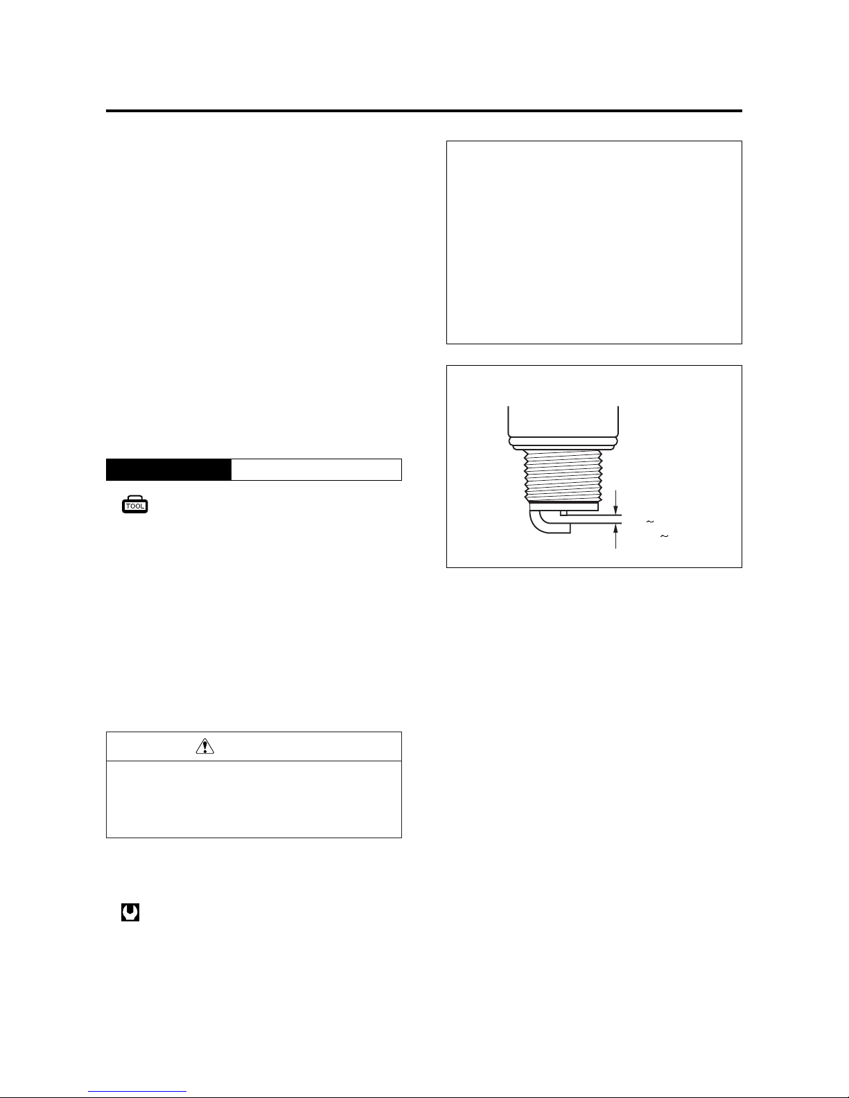
0.7 0.8 mm
(0.028 0.032 in)
0.7 ∼ 0.8 mm (0.028 ~ 0.032 in)
Spark plug gap
▣▣
CARBON DEPOSITS
Check to see if there are carbon deposits on the
spark plug.
If carbon is deposited, remove it using a wire or pin
with a pointed end.
▣▣
SPARK PLUG GAP
Measure the spark plug gap using a thickness
gauge.
If the spark plug gap is out of specification, adjust the
gap.
▣▣
ELECTRODE
Check to see the worn or burnt condition of the electrodes.
If it is extremly worn or burnt, replace the spark plug
with a new one.
And also replace the spark plug if it has a broken
insulator, damaged thread, etc.
● Insert the spark plug and finger tighten it to the
cylinder head and then tighten it to the specified
torque.
Spark plug : 11 N··m (1.1 kgf··m)
Thickness gauge : 09900-20806
CAUTION
To avoid damaging the cylinder head threads ;
first, finger tighten the spark plug, and then tighten it to the specified torque using the spark plug
wrench.
2-7 PERIODIC MAINTENANCE
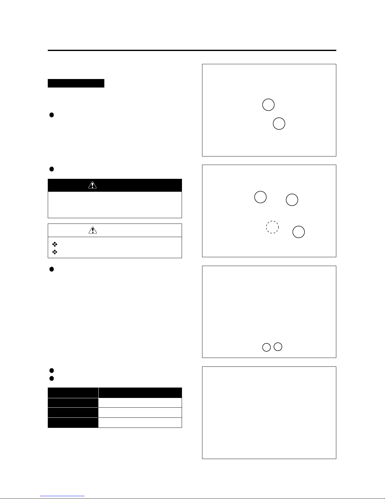
EXHAUST PIPE BOLTS AND
MUFFLER MOUNTING BOLTS
Tighten the exhaust pipe bolts ①, and muffler
mounting bolts ②to the specified torque.
Inspect Interval
Tighten Initial 1,000 km and Every 6,000 km thereafter.
Rear Cylinder
Front Cylinder
①
①
AIR CLEANER
If the air cleaner is clogged with dust, intake resistance will be increased, with a resultant decrease in
power output and an increase in fuel consumption.
Check and clean the air cleaner element in the following manner :
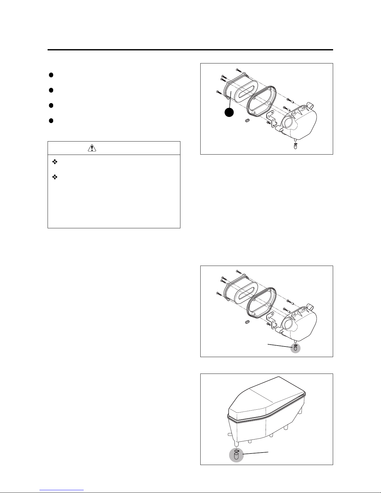
● Remove the air cleaner cover ④ by loosening the
two air cleaner cover screws ③.
● Loosen the four air cleaner element screws ⑤.
● Remove the air cleaner element .
Inspect Interval
Clean Every 3,000 km,
Replace Every 12,000 km.
Exhaust pipe bolt
: 18 ~ 28 N
m (1.8 ~ 2.8 kgf m)
Muffler mounting bolt
: 20 ~ 25 N
m (2.0 ~ 2.5 kgf m)
②
③
④
❺
❺
PERIODIC MAINTENANCE 2-8
Clean the air cleaner element for the following :
When the air cleaner element clean with the air gun,
necessarily blow at the inside by compressed air.
Carefully examine the air cleaner element for tears during
cleaning. Replace it with a new one if it is torn.
Assemble the element completely or damage severely
the engine.
Be careful not to allow water to go inside the air clea-
ner element.
▣▣
AIR CLEANER OIL DRAIN PLUG
Inspect the plug ① and drain water and oil at the
periodic maintenance interval.
The air cleaner oil drain plug ① is located beneath
the air cleaner case.
CAUTION
Inspect the air cleaner element for tears.
A torn element must be replaced.
If driving under dusty conditions, clean the air
cleaner element more frequently. The surest
way to accelerate engine wear is to operate the
engine without the element or with torn element. Make sure that the air cleaner element is
in good condition at all times. Life of the
engine depends largely on this component!
①
▣▣
AIR CLEANER CHAMBER OIL
DRAIN PLUG
Inspect the plug ② and drain water and oil at the
periodic maintenance interval.
The air cleaner chamber oil drain plug ② is located
beneath the air cleaner chamber.
②
2-9 PERIODIC MAINTENANCE
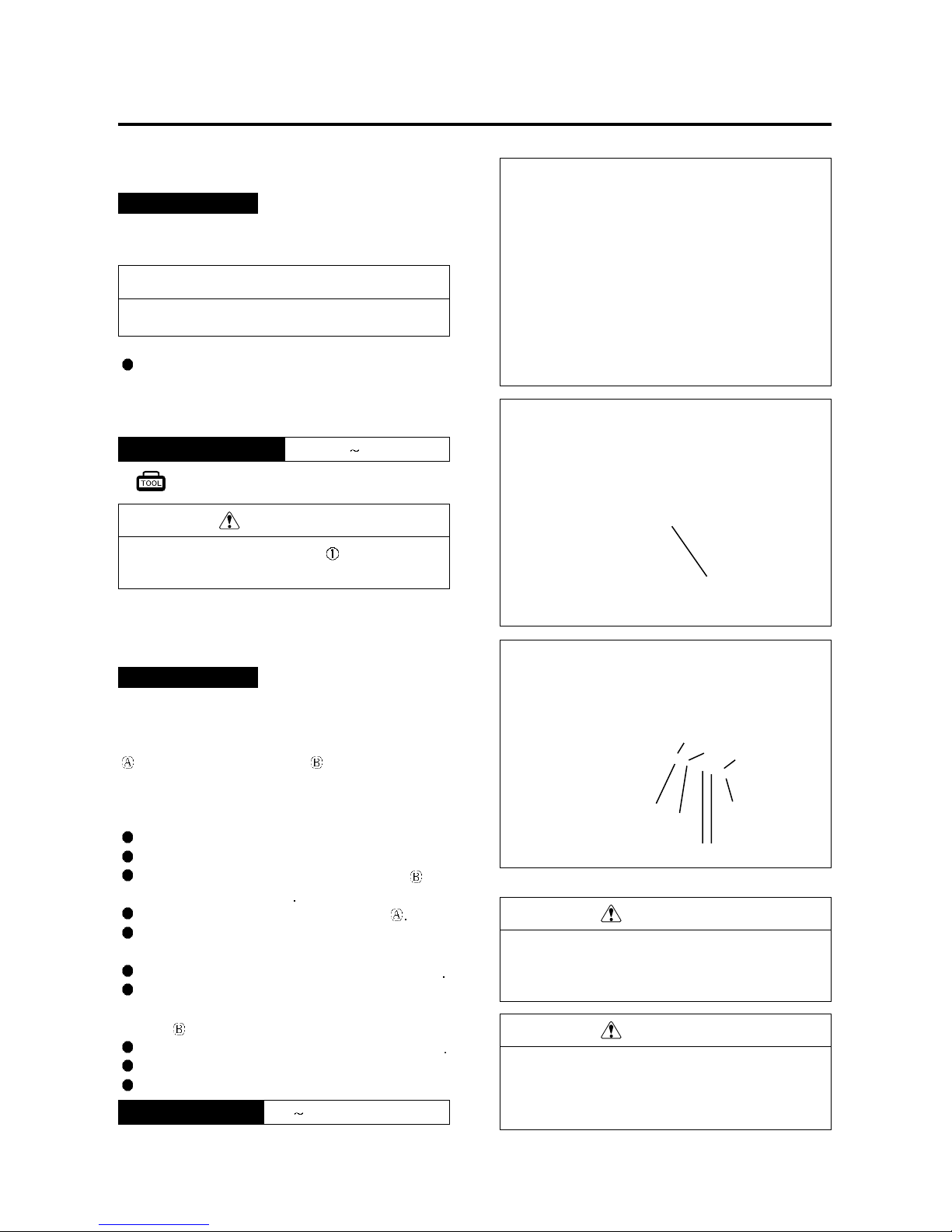
THROTTLE CABLE PLAY
This motorcycle has a twin throttle cable system. Cable
is for throttle cable and cable is for returning cable.
There should be 0.5 ~ 1.0 mm (0.02 ~ 0.04 in) play on
the throttle cable.
To adjust the throttle cable play :
Hold the motorcycle vertically.
Uncover the protection.
Loosen the lock nut ②of the returning cable and
fully turn in the adjuster
③
Loosen the lock nut ④of the throttle cable
Turn the adjuster ⑤in or out until the throttle cable
play is between 0.5 ~ 1.0 mm (0.02 ~ 0.04 in).
Tighten the lock nut ④while holding the adjuster
⑤
While holding the throttle grip at the fully closed posi-
tion, slowly turn out the adjuster ③of the returning
cable until resistance is felt.
Tighten the lock nut ②while holding the adjuster
③
Check free play again.
Cover the protection.
Connect an engine tachometer to the high ten-
sion cord.
Start the engine and inspect the engine idle
speed between specified range.
1,400 1,600 rpmEngine idle speed
0.5 1.0 mm (0.02 ~ 0.04 in)Throttle cable play
ENGINE IDLE SPEED
Inspect Interval
Inspect Initial 1,000 km and Every 6,000 km thereafter.
Inspect Interval
Inspect Initial 1,000 km and Every 6,000 km thereafter.
NOTE
④
⑤
③
①
②
0.5 ~ 1.0 mm
(0.02 ~ 0.04 in)
Make this inspection when the engine is hot.
CAUTION
Never operate the idle screw to avoid variations of the carburetion setting.
Engine tachometer : 09900-26006
CAUTION
After the adjustment is completed, check that
throttle grip movement does not raise the engine
idle speed and that the throttle grip returns
smoothly and automatically.
CAUTION
Inadequate throttle cable play can cause engine
speed to rise suddenly when you turn the throttle
grip. This can lead to loss of rider control.
PERIODIC MAINTENANCE 2-10
FUEL HOSE
Remove the seat. (Refer to page 8-1)
Remove the fuel tank. (Refer to page 5-2)
Remove the frame cover. (Refer to page 8-2)
Inspect the fuel hoses for damage and fuel leakage.
If any defects are found, the fuel hoses must be
replaced.
Inspect Interval
Inspect Initial 1,000 km and Every 6,000 km thereafter.
Replace every 4 years.
①
⑤
②
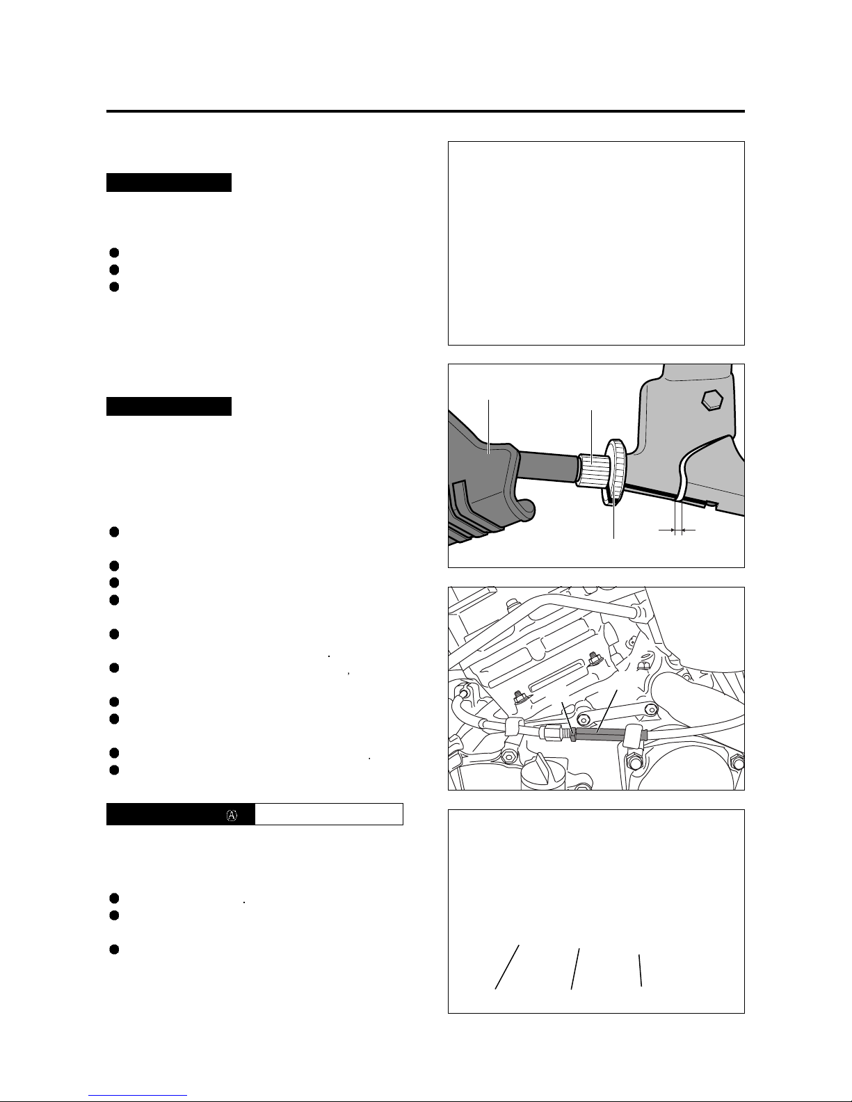
CLUTCH
Clutch play should be 2 mm (0.08 in) as measured at the
clutch lever holder before the clutch begins to disengage.
If the play in the clutch is incorrect, adjust it in the following
way :
A basis adjustment be allowed by the clutch lever
adjuster ②.
Uncover the rubber boot ⑤.
Loosen the lock nut ①counter-clockwise.
Turn the clutch lever adjuster ②in or out to acquire
the specified play.
After end of adjustment, tighten the lock nut ①clock-
wise fully and cover the rubber boot
⑤
If not adjust by the clutch lever adjuster ②adjust by
the clutch cable adjuster ④.
Loosen the clutch cable adjuster lock nut ③.
Turn the clutch cable adjuster ④in or out to acquire
the specified play.
After end of adjustment, tighten the lock nut
③
The clutch cable should be lubricated with a light
weight oil whenever it is adjusted.
▣▣
GEARSHIFT LEVER HEIGHT
ADJUSTMENT
Loosen the lock nut
⑥
With the link rod ⑦turned, adjust the gearshift lever
height.
Tighten the lock nut ⑥.
2 mm (0.08 in)Clutch cable play
Inspect Interval
Inspect Initial 1,000 km and Every 6,000 km thereafter.
⑥
⑥
⑦
④
③
2-11 PERIODIC MAINTENANCE
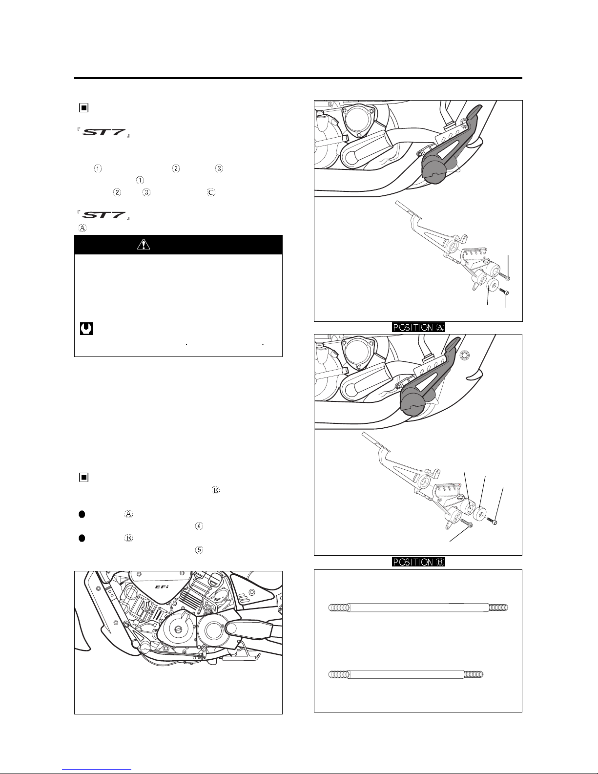
FOOTREST POSITION ADJUST-
MENT
has 2 type of the footrest position, right
and left.
To change the position, remove the footrest mounting
bolt , footrest boss cap and bolt .
Install the bolt to the desired position and footrest
boss cap , bolt to the position .
is delivered from the factory on position
.
GEARSHIFT LINK ROD
When the footrests in position , exchange the
gearshift link rod for appropriate riding position.
Position
: Install the gearshift link rod
Position
: Install the gearshift link rod
②
③
③
①
④
⑤
Footrest mounting bolt
: 40 ~ 60 N m (4.0 ~ 6.0 kgf m)
①
②
WARNING
When adjusting the footrest position, the footrest
mounting bolt be torque to the proper specification.
If they are not, the footrest can come off unexpectedly.
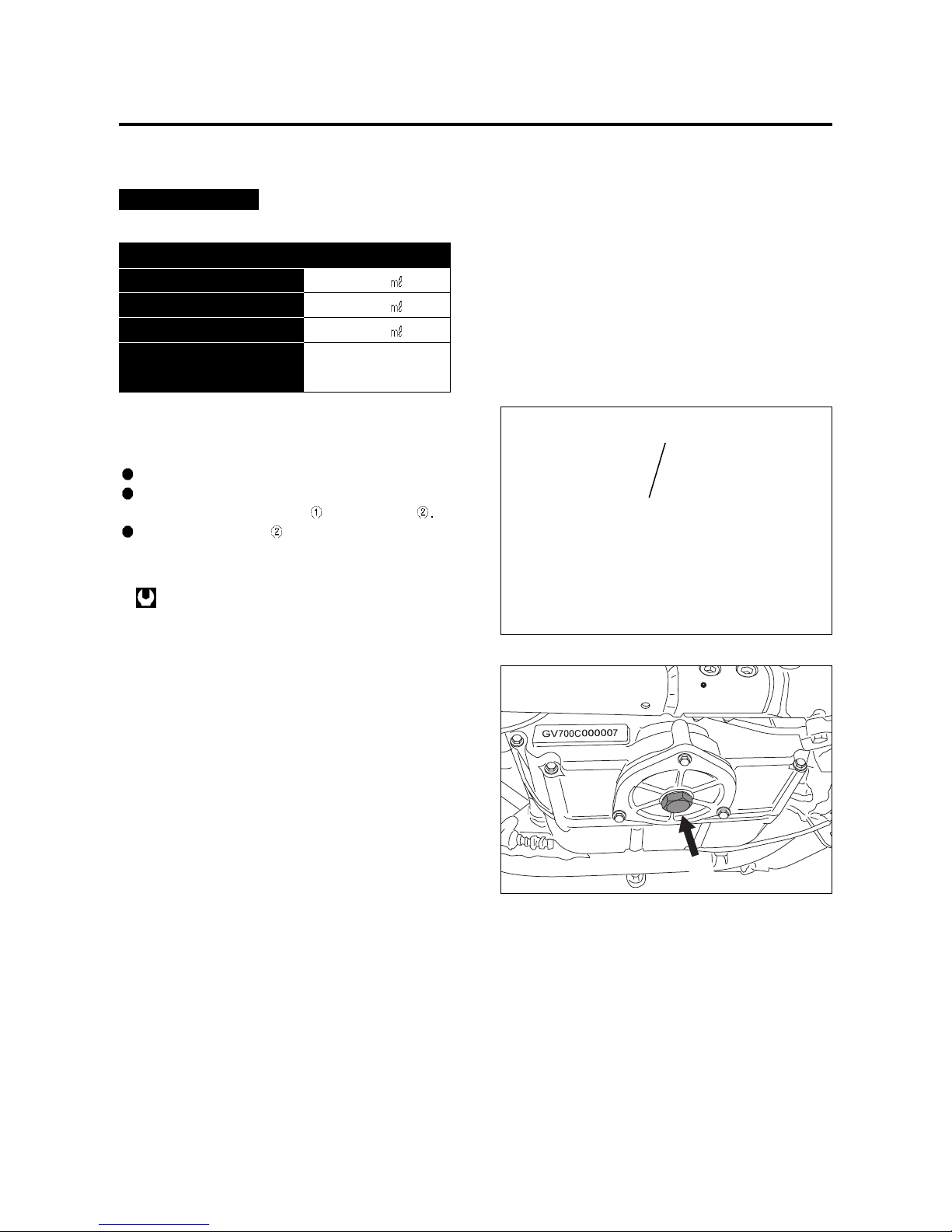
PERIODIC MAINTENANCE 2-12
Necessary amount of engine oil
Oil change
Oil and filter change
Engine overhaul
Engine oil type
SAE 10W/40
API Over SL
3,000
3,200
3,400
ENGINE OIL
Inspect Interval
Replace Initial 1,000 km and Every 6,000 km thereafter.
The oil should be changed while the engine is warm.
Oil filter replacement at the above intervals,
should be together with the engine oil change.
Keep the motorcycle upright.
Place an oil pan below the engine, and drain the
oil by removing the filler cap and drain plug
Tighten the drain plug to the specified torque, and
pour fresh oil through the oil filler. Use an API classification of Over SL oil with SAE 10W/40 viscosity.
Oil drain plug : 21 N··m (2.1 kgf··m)
②
①
 Loading...