

Hyline Offroad JK SERIES STANDARD REAR TIRE CARRIER User Manual
USA
Present Jeep Wrangler &
Swingout Tire
Carrier. Our Products are completely manufactured in our facility located in
Perkasie, PA. They are designed and engineered by Offroad enthusiasts just like
you to be rock solid at an affordable price. Hyline Offroad would like to thank
Hyline Offroad Staff
Hyline Offroad StaffHyline Offroad Staff
Hyline Offroad Staff
Qty:
1 Swingout Tire Carrier
1 Slide Adjustable Tire Mount
1 Black Tailgate Bracket Plate
1 Machined Pivot Pin
1 Machined White Plastic Alignment Block
2 Brass Washers for Pivot Pin
4 ½”-13 x 1-1/2 Gr. 8 Hex Head Bolts
1 ½”-13 x 1” Gr. 8 Hex Head Bolt
5 ½” Lock Washers Gr. 8
5 ½” Flat Washers Gr. 8
2 5/16”-18 x 1-3/4” Gr. 5 Hex Head Bolts
4 5/16” Flat Washers Gr. 5
2 5/16”-18 Nylok Hex Nut Gr. 5
2 3/8” Flat Washers Gr. 5
2 3/8”-24 Nylok Hex Nut Gr. 5
1 3/8”-24 RH Thread Thin Hex Nut Gr. 5
1 3/8”-24 LH Thread Thin Hex Nut Gr. 5
1 Right Hand Thread Ball Joint Rod End
1 Left Hand Thread Ball Joint Rod End
1 Aluminum Connector Rod
3 Wheel Studs
1 1/8” PTF Stainless Steel Grease Fitting
Proudly Made In
Installation Instructions:
JK Gen II Swingout Tire Carrier
Part Number: JK-21STC
13mm Socket
¾” Socket
½” Socket
9/16” Socket
T20 Torx Bit
Grease Gun
Lithium Grease
Congratulations on your purchase of the Hyline Offroad Gen II
½” Wrench
¾” Wrench
7/16” Wrench
Wire Cutters
Vehicle Fitment:
2007Unlimited
5 lb. Hammer
Or Heavy Duty Vise
T:\Hyline Offroad, LLC\Installation Instructions\JK-21STC\JK-21STC Installation Instructions.doc
REV 3 1/9/2012
you for your recent purchase and look forward to serving you in the future.
Page 1 of 4
Generation II Swingout Tire Carrier Installation
PLEASE READ INSTRUCTIONS BEFORE BEGINNING INSTALLATION
Remove Tire Carrier
Remove Brake Light
Note: Two Plastic Alignment Blocks have been provided. Use whichever block works best to align swingout carrier parallel to the tailgate.
Step 1 – If you have not already installed your Hyline Offroad Rear Bumper that accepts this tire carrier please do
so using the Installation Instructions for P/n JK-20SRB(T).
***BEFORE INSTALLING TIRE CARRIER ON THE BUMPER
***COMPLETE STEPS 2 & 3
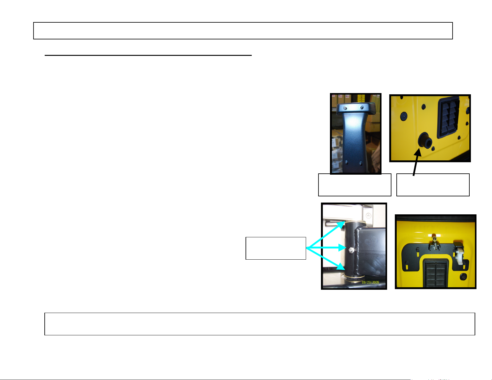
Step 2 – First remove the Brake Light Back Cover by unscrewing the 4 torx
screws using the T20 bit (Fig.1) & unplug wires. Wires should hang
freely. Then, remove the stock Tire Carrier by unbolting the eight bolts
using the 13mm” Socket. Then remove the 2 black rubber mounts that
the stock tire pressed against. These remove by simply pulling them
away from the body on an angle. (See Fig.2)
Step 3 – Install the Stainless Steel Grease Fitting using the 7/16” Wrench.
The grease fitting has pipe threads which are tapered to obtain
a leak free seal. Because of the tapered threads you may not
be able to completely screw in the grease fitting. Note: Location of
fitting might vary from picture in Figure 3.
Step 4 – Install the supplied tailgate bracket using 4 bolts
that were previously removed from stock tire carrier (Do Not Tighten
Yet). Install Rod End Fitting using one 3/8” flat washer & 3/8”-24 hex
Nut & tighten. Also install the white plastic Alignment block using
two-5/16” bolts, four-5/16” flat washers & two-5/16” hex lock nuts.
Typically 2012-Present JK’s will use the shorter block.
Brass Washers
& Grease Fitting
Figure 1
Back Cover
Figure 3
& Rubber Bumpers
Figure 2
Figure 4
T:\Hyline Offroad, LLC\Installation Instructions\JK-21STC\JK-21STC Installation Instructions.doc
REV 3 1/9/2012
Page 2 of 4
 Loading...