

Page 1
CM-1391M
Video to DVI
Scaler Box
Operation Manual
CM-1391M
Page 2

Disclaimers
Copyright Notice
Trademark Acknowledgments
The information in this manual has been carefully checked and
is believed to be accurate. Cypress Technology assumes no
responsibility for any infringements of patents or other rights of third
parties which may result from its use.
Cypress Technology assumes no responsibility for any inaccuracies
that may be contained in this document. Cypress also makes
no commitment to update or to keep current the information
contained in this document.
Cypress Technology reserves the right to make improvements to
this document and/or product at any time and without notice.
No part of this document may be reproduced, transmitted, transcribed, stored in a retrieval system, or any of its part translated into
any language or computer file, in any form or by any means electronic, mechanical, magnetic, optical, chemical, manual, or
otherwise - without express written permission and consent from
Cypress Technology.
© Copyright 2010 by Cypress Technology.
All Rights Reserved.
Version 1.0 November 2010
All products or service names mentioned in this document may be
trademarks of the companies with which they are associated.
Page 3

Safety Precautions
Revision History
Version No Date Summary of Change
VR0 20101210 Preliminary Release
Please read all instructions before attempting to unpack or install or
operate this equipment, and before connecting the power supply.
Please keep the following in mind as you unpack and install this
equipment:
Always follow basic safety precautions to reduce the risk of
fire, electrical shock and injury to persons.
To prevent fire or shock hazard, do not expose the unit to rain,
moisture or install this product near water.
Never spill liquid of any kind on or into this product.
Never push an object of any kind into this product through
module openings or empty slots, as you may damage parts.
Do not attach the power supply cabling to building surfaces.
Do not allow anything to rest on the power cabling or allow it to
be abused by persons walking on it.
To protect the equipment from overheating, do not block the
slots and openings in the module housing that provide
ventilation.
Page 4

Table of Contents
1. Introduction............................................................................... 1
2. Application................................................................................ 1
3. Package Contents.................................................................... 1
4. System Requirements................................................................ 1
5. Features...................................................................................... 1
6. Specifications............................................................................ 2
7. Operation Controls and Functions.......................................... 2
8. Output Format .......................................................................... 3
9. OSD Operation.......................................................................... 4
10. DVI-I Pin Configuration........................................................... 5
11. Remote Control....................................................................... 5
12. Connection and Installation.................................................. 6
Page 5

1. Introduction
3. Package Contents
1. Video Scaler Unit.
2. DC adaptor
3. User Manual
4. Remote Control
5. Features
11
1. Motion adaptive 3-D deinterlacing
2. Supports 3D Y/C separation, or 2D 5-Line (5H) Adaptive Comb
3. Advanced 3D motion adaptive deinterlace
4. Automatic 2:2/3:2 film mode detection
5. Supports 50Hz to 60Hz frame rate conversion
6. Video quality improvement:
DCTI (Digital chroma transient improvement), DLTI (Digital luminance
transient improvement), Black level extension
7. OSD menu for picture quality adjustment
8. Front Panel and IR remote control
9. Automatic NTSC/PAL video format detection
2. Application
* Digital/Analog composite signal display on DVI monitor
* Digital/Analog S-Video signal display on DVI monitor
* NTSC/PAL signal display on DVI monitor
* DVD/VCR signal display on DVI monitor
4. System Requirements
Input source equipment such as Set-Top-Box or DVD player and output DVI
display with connection cables.
This professional video scaler is designed to convert Composite and S-Video
to high definition DVI resolutions. It handles video input from TV systems of
NTSC or PAL standards with many great features to enhance video
performance on DVI display.
Page 6

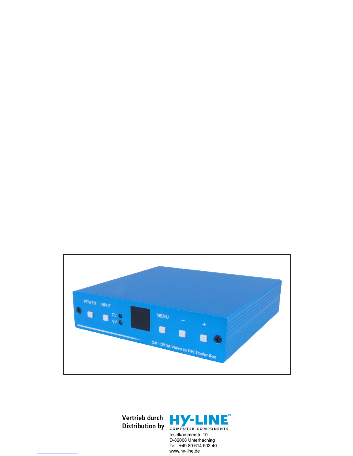
1. Power button and LED indicator:
Press the button once to power on the unit, Press again to power off.
when the unit is powered on, one of the input LEDs will illuminate depending on
your last selection of input source before power off.
The factory default setting for the input is CV (composite video).
The green LED illuminates when composite video is selected.
The Yellow LED illuminates when S-Video is selected.
2. Input select button:
Press the button to select your desired input source between composite
video and S- Video.
3. IR Sensor: Infrad remote control sensor.
Front Panel
7. Operation Controls and Functions
2
6. Specifications
Output Signal Specifications
POWER INPUT MENU
CM-1391M Video to DVI Scaler Box
CV
SV
1 2 3 4 5 6
Input Signal Levels
Video@1Vp-p, 75 ohm, Y@1 Vp-p, 75 ohm
Color@ 0.7 Vp-p, 75 ohm
Digital RGB
Output Connector
Output Signal
Bit stream
Weight(g) 400
125(W) x 123(D) x 30(H)
0°C~40°C
Process Blue
4.5W
Dimensions(mm)
Output Format
DVI-I Connector
Operating Temperature
Silkscreen Color
Power Consumption
HDTV (RGBHV)HDTV (RGBHV)PC (RGBHV)PC (RGBHV)
VGA 640 x 480 60Hz 1080p-RGB 1920 x 1080p Follow input source and can
convert 50Hz to 60Hz
SVGA 800 x 600 60Hz 1080i-RGB 1920 x 1080i Follow input source and can
convert 50Hz to 60Hz
XGA 1024 x 768 60Hz 720p-RGB 1280 x 720 Follow input source and can
convert 50Hz to 60Hz
1280 x 800 60Hz 576-RGB 720 x 576 50Hz
WXGA 1366 x 768 60Hz 480P-RGB 720 x 480 60Hz
WSXGA 1680 x 1050 60Hz
SXGA 1280 x 1024 60Hz
1400 x 1050 60Hz
1680 x 1050@60RB 60Hz
UXGA 1600 x 1200 60Hz
WUXGA 1920 x 1200 60Hz
1920 x 1080@60RB 60Hz
Page 7

4. Menu/Enter: This button serves two purposes.
a. Press the button to bring up OSD main control menu as shown in the "OSD Operation".
b. To act as a "enter" key to enter sub menu of you selected item or adjust
value of the selected item.
5/6. +/- button: Press the button to move up or down the tick "V" to your
desired parameter. Or after a parameter is selected by pressing MENU/ENTER button,
press the button to alter the value of your selected parameter.
3
8. Output Format
a. The format of digital DVI output is digital RGB for all resolutions.
-RGB
-RGB
-RGB
-RGB
-RGB
1080i-RGB
720p-RGB
576p-RGB
480p-RGB
1920x1080i
1280X720
720X576
720X480
UXGA
WUXGA -RGB
-RGB
1600 x 1200
1920 x 1200
1080p-RGB
1920x1080p
follow input source
follow input source
follow input source
1. DC power jack: 5V 1A DC power input.
2. Composite Video:
Use a Composite video cable to connect the composite video
output of the source equipment to this composite video(CV) input of the scaler.
3. S-Video: Use a S-Video cable to connect the S-Video output of the source
video equipment to this " S-Video" input on the back of the video scaler.
S-Video provides improved performance over composite video and is
recommended over composite.
4. DVI output: The Video to DVI Scaler Box can output a variety of PC and HDTV
progressive resolutions, in both digital and analog format through DVI-I
connector.
Digital output: Connect Video to DVI Scaler Box's digital DVI output to the DVI
input of your TV/display unit using a DVI to DVI cable.
Analog output: If you are to use Video to DVI Scaler Box's analog output to
connect to the
analog input of your PC or HDTV, you need to use a DVI to VGA
adaptor to pull out analog signal from the DVI-I connector . The DVI to VGA
adaptor is then connect to the VGA input of your display monitor through a
VGA cable if output is PC resolution,
or connect to the YPbPr input
through
a RCA adaptor cable if output is HD resolution.
Note: DVI to VGA adaptor is not included in the standard package,
and has to order separately.
Rear Panel
4
3
2
1
DC 5V
SV CV
DVI-I OUTPUT INPUT
Page 8

4
Output Setup
When Output Set up is selected a submenu as below appears:
Output Setup
Timing XGA
Exit
Press the " MENU/ENTER" button to enter into output timing select mode.
Press +,- to toggle through a variety of output resolutions as below.
Once your desired resolution is selected. press the menu/enter
to enter the resolution.
Use +,- button to move "V" to your desired parameter, then press MENU/ENTER
to enter into sub-menu of your selected parameter.
Picture Adjust
When Picture Adjust is selected a sub menu as below comes up.
Bright
Contrast
Color
Tint
Sharp
Default
Exit
USE +,- to move the tick (V) to your desired adjust item, Press the Menu/Enter
to confirm
your selection.
At this point, the selected parameter will turn red, and you can use +,- to increase
or decrease the value of the parameter.
When adjustment is complete, Press "Menu" to leave the parameter. Move the tick "V"
to "Exit", then press menu/enter to exit.
9. OSD Operation
After power on the unit , press the menu button to bring up the main menu
page as below:
Main Menu
Picture adj.
Output Setup
Exit
Default Range
16
16
16
16
05
OK
1-31
1-31
1-31
1-31
1-19
b. The format for analog PC output is RGB.
-RGB
-RGB
-RGB
-RGB
-RGB
UXGA
WUXGA -RGB
-RGB
1600 x 1200
1920 x 1200
Page 9

5
10. DVI-I Pin Configuration
1 8 C1 C2
C5
C4
C3
9
17 24
Combined Analog and Digital Connector Pin Assignments
Pin Signal Assignment Pin Signal Assignment
1
2
3
4
5
6
7
8
C1
C4
T.M.D.S Data2-
T.M.D.S. Data2+
T.M.D.S. Data2 Shield
N.C.
N.C.
DDC Clock
DDC Data
Analog Vertical Sync
Analog Red
Analog Horizontal Sync
9
10
11
12
13
14
15
16
C2
C5
T.M.D.S Data1-
T.M.D.S. Data1+
T.M.D.S. Data1 Shield
N.C.
N.C.
+5V Power
Ground
(Return for +5V, Hsync, and Vsync)
Hot Plug Detect
Analog Green
Analog Ground
(Analog R,G,&B return)
Pin Signal Assignment
17
18
19
20
21
22
23
24
C3
T.M.D.S Data0-
T.M.D.S. Data0+
T.M.D.S. Data0 Shield
N.C.
N.C.
T.M.D.S. Clock Shield
T.M.D.S. Clock+
T.M.D.S. Clock-
Analog Blue
DVI-Integrated(DVI-I): Supports both analog and digital connections to the display.
This 29-pin connector can carry single or dual-link all-digital video/data signals
on 24 pins and uses 5 pins to carry analog video/data signals and ground.
Vertical rate
Resolution
VGA
SVGA
XGA
WXGA
SXGA
UXGA
WUXGA
480p
576p
720p
1080i
1080p
640x480
800x600
1024x768
1280x768
1280x1024
1600x1200
1920x1200
720x480
720x576
1280x720
1920x1080i
1920x1080p
60Hz
60Hz
60Hz
60Hz
60Hz
60Hz
60Hz
60Hz
50Hz
follow input source and can convert 50Hz to 60Hz
follow input source and can convert 50Hz to 60Hz
follow input source and can convert 50Hz to 60Hz
Page 10

6
12. Connection and Installation
VCR, DVD, STB, DVHS
PC display Monitor,
Projectors
DVI
output
Video,
SVideo
DVI
Input
DVI Cable
a. Digital Out: Connect to your TV through digital DVI interface
VCR, DVD, STB, DVHS
CV
SV
b. Analog Out: Connect to your TV through VGA or component interface
in case your TV has no DVI input
Analog
HDTV output
VGA to RCA cable
VGA cable
Analog
PC output
DVI to
VGA
Adaptor
11. Remote Control
13
4
2
1. Display: Press the button to display input source
and output resolution on the screen.
2. Power: Power ON/OFF button.
3. VGA~1080p: Press to select your desired
output resolution.
4. Picture: Press the button to enter picture
adjust submenu. Use +,- button to move
cursor (V) up/down to your desired
parameter, press "Picture" again to
confirm.
5. +/-: Press to move up/down the cursor (V)
to your desired parameter,or press to
increase/decrease the setting value.
6. Reset: Press to reset all setting back to
factory default value.
7. Exit: To exit OSD.
8. Video: Press the button to select
composite video input.
9. SVideo: Press the button to select
SVideo input.
6
55
8
7
9
5
VIDEO
VGA SVGA
XGA
WXGA
SXGA
480p
720p
1080i
PICTURE
RESET EXIT
-
+
576p
UXGA
1080p
WUXGA
SVIDEO
CR-58
Page 11

Acronyms
A
Acronym Complete Term
CV Composite Video
NTSC National Television System Committee
OSD On-Screen-Display
PAL Phase Alternating Line
RGB Red Green Blue
SV S-Video
Page 12

20101105 MPM-CM1391M
Home page: http://www.cypress.com.tw
CYPRESS TECHNOLOGY CO.,LTD .
 Loading...