

HygroMatik WL-ROB-170, WL-RO-170 User Manual
Reverse osmosis plants
WL-ROB-170
WL-RO-170
ÁWLROB170.ENxÈ
WLROB170.EN
Manual
Page 2
Warning! Hazardous Voltage: All work to be performed by trained personnel only.
All electrical installation and servicing of the electrical components of this unit to
be performed by qualified electricians only. Disconnect power supply before installa
-
tion and servicing!
Copyright © HygroMatik GmbH [21.11.2018]
WL-RO-170, WL-ROB-170
All rights reserved.

Page 3
1. About this documentation ................................................................................................ 5
1.1 Intended use ..................................................................................................................... 5
1.2 Structure ............................................................................................................................ 6
1.3 Depictions .......................................................................................................................... 7
1.3.1 Action steps .................................................................................................................... 7
1.3.2 Safety instructions and information notes ...................................................................... 7
1.4 The documentation is part of the system .......................................................................... 7
1.5 Customer service .............................................................................................................. 8
2. Safety .................................................................................................................................. 9
2.1 Measures for safe operation .............................................................................................. 9
2.2 Personnel .......................................................................................................................... 10
2.3 Personal protective equipment .......................................................................................... 10
2.4 Safety-conscious working .................................................................................................. 11
3. Transport and storage ...................................................................................................... 13
3.1 Transport notes ................................................................................................................. 13
3.2 Scope of supply ................................................................................................................. 13
3.3 Inspecting for correctness and completeness ................................................................... 13
3.4 Storage .............................................................................................................................. 13
3.5 Preservation ...................................................................................................................... 14
4. System description .......................................................................................................... 15
4.1 Principle of osmosis/reverse osmosis ............................................................................... 15
4.2 Overview of components ................................................................................................... 15
4.3 Functional description ....................................................................................................... 17
5. Technical Data ................................................................................................................... 19
5.1 Raw water requirements regarding water quality .............................................................. 19
5.2 Raw water requirements regarding pressure .................................................................... 19
5.3 Permeate quality ............................................................................................................... 19
5.4 Performance data .............................................................................................................. 20
5.5 Dimension sheet ................................................................................................................ 21
5.6 Emissions .......................................................................................................................... 23
5.6.1 Operating and auxiliary materials ................................................................................... 23
5.6.2 Noise emission from the system .................................................................................... 23
6. Mounting ............................................................................................................................ 24
6.1 Mounting the securing and fixing plate .............................................................................. 24
6.2 Connecting the plant ......................................................................................................... 25
7. Inital start-up (System was preserved by manufacturer) .............................................. 27
8. Settings .............................................................................................................................. 29
8.1 Setting the switch-off pressure .......................................................................................... 29
8.2 Setting raw water inlet pressure on the pressure regulator ............................................... 31
9. Production/Stand-by operation ........................................................................................ 32
9.1 Starting production ............................................................................................................ 32
9.2 Set blending (ROB plant only) ........................................................................................... 33
9.3 Stand-by operation ............................................................................................................ 34

Page 4
9.4 System shut-down ............................................................................................................. 34
10. Diagnostics ...................................................................................................................... 35
10.1 System state .................................................................................................................... 35
10.2 Rest fault indication ......................................................................................................... 37
10.3 Involve HygroMatik service personnel ............................................................................. 37
11. Maintenance ..................................................................................................................... 38
11.1 Replacing the membrane ................................................................................................ 38
11.2 System separator: Maintaining and cleaning the cartridge ............................................. 41
11.3 Pressure regulator: inspect valve insert and strainer ...................................................... 42
11.4 Pressure regulator: replace backflow preventer .............................................................. 43
11.5 Pressure regulator functional check ................................................................................ 43
11.6 Drain valve functional check ............................................................................................ 43
11.7 Functional checks with pressure check equipment. ........................................................ 43
12. Placing out of operation and preservation ................................................................... 44
13. Spare parts ....................................................................................................................... 47

Page 5
1. About this documentation
1.1 Intended use
This system is a water treatment system for preparing drinking
water, according to current drinking water standards for
desalinated water (conductivity: from 5 to 20 µS/cm).
Desalinated water may e.g. be used for filling humidifiers or any
other system that can be operated using desalinated water.
All components and operating equipment used in the system are
directly or indirectly required to ensure the desired treatment
result.
Any use of the plant and the water produced that differs to that
described in this document is considered to be improper.
The use of components and equipment for other purposes than
their use in the system, as well as the drawing of water for
purposes other than the specified use is deemed improper. The
water produced, e.g., must not be used as drinking water.
HygroMatik GmbH accepts no liability for damages that occur as
a result of improper use. The risks associated with improper use
lie solely with the operator.
PLEASE NOTE
In order to protect against flooding caused by supply or product
water or drained water, the device location should feature a
pressureless floor grid. In case of non-existance, proper safety
precautions for leakage protection must be considered. HygroMatik may not be held responsable for any damage resulting
from disregard of this recommendation.
PLEASE NOTE
Use of a prefilter (E-7705200) and a 10 µm particle filter (E-
7621028) is recommended.

Page 6
1.2 Structure
In these Operating and maintenance instructions, you can find
all descriptions and instructions required for safe and proper
operation and for service and inspection of the system.
If you have questions or suggestions for improvement on this
documentation, refer to HygroMatik GmbH.
Tel.: +49-(0)4193 / 895-0 (Cental office)
Tel.: +49-(0)4193 / 895-293 (Technical Hotline)
Fax: +49-(0)4193 / 895-33
E-mail: hot1@HygroMatik.de
Pls., have the device data available when contacting us for consultation or the ordering of spare parts.
Page 7
1.3 Depictions
1.3.1 Action steps
1.3.2 Safety instructions and information notes
In this document, general, basic and specific safety precautions
are given to draw attention to dangers in handling the system
and to unavoidable residual risks in the operation of the plant.
WARNING!
... indicates a potentially dangerous situation, that could lead to
death or serious injury, if not avoided..
CAUTION!
... indicates a potentially harmful situation in which the system or
an object could be damaged in their surroundings.
PLEASE NOTE
... points to information to better understand the complex
processes, for efficient and trouble-free operation.
Notes basically contain no safety instructions.
Danger due to electric current
DANGER!
... identifies hazards caused by electric current. Ignoring the
safety instructions can result in severe injury or death
1.4 The documentation is part of the system
These Operating and maintenance instructions are part of the
system. Keep this document to hand during the entire life cycle
of the system and add any changes, that you receive from
HygroMatik GmbH.
Step Action Result
1 Follow this instruction Description of result after execution of
the instruction
2 ... ...

Page 8
1.5 Customer service
In the following cases, contact HygroMatik GmbH customer service:
• Ordering replacement parts
• Troubleshooting
• Maintenance
For contact data, s. section 1.2 .

Page 9
2. Safety
The system is constructed and built according to the standards
to be adhered to, as well as other technical specifications. The
system therefore is in line with state-of-the-art technology and
achieves the highest degree of safety during operation.
Safety instructions
The safety instructions contained in these Operating and
maintenance instructions and other country-specific regulations
and instructions must be read carefully and strictly adhered to, in
order to reduce possible health hazards and prevent dangerous
situations.
In this chapter, general safety precautions are given to draw
attention to dangers in handling the system and to unavoidable
residual risks.
Action-related safety instructions are preceded by the
corresponding instructions.
The chapter on "Safety" is of fundamental importance and must
be carefully read and strictly observed. This is the only way to
ensure that all operations and tasks on the system are carried
out safely and correctly.
Failure to observe the safety instructions can result in danger to
persons and material damage to the system.
2.1 Measures for safe operation
The safety of the system during operation can then only be
achieved if all the measures required for this have been taken.
The operator is required to plan and execute, as well as review,
these measures as a matter of due diligence.
Proper use and condition of the system
The operator must ensure that ...
• the system is only used as properly intended.
• the system is only operated when in faultless, functional
condition.
• the system is not changed or added to without authorisation.
Personnel
The operator must ensure that only qualified, authorised personnel operate and service the system.
Personal protective equipment and information and warning signs
The operator must ensure that ... …
• the required personal protection equipment is available
and worn by qualified and authorised personnel.
Page 10
• all information and warning signs affixed to the system are
not removed and are legible.
Training in occupational safety and environmental protection
The operator must ensure that qualified, authorised personnel
are regularly trained in all questions relating to occupational
safety and environmental protection.
Operating and maintenance instructions
The operator must ensure that ...
• the Operating and maintenance instructions are always
present, legible and complete at the place of use of the
system.the Operating and maintenance instructions and in
particular, the safety notes contained therein are familiar.
2.2 Personnel
WARNING!
Risk of injury/material damage due to insufficient experience
Improper use of the system can lead to personal injury and damage.
Therefore:
• Activities on the system may only be carried out by named,
qualified and authorised personnel.
• Essentially, people may only be permitted to work on the
system if they are expected to perform the work reliably.
• People who are under the influence of drugs, alcohol or
medication are not permitted.
The following qualification requirements are imposed on personnel:
•Qualified, experienced specialists
• Knowledge of pipeline and plant construction as well as
water treatment
• Knowledge and experience of handling the preparation of
the piping material and connections to be laid
• Knowledge of the following standards:
DIN 1988
DIN EN 1717
DIN EN 806
2.3 Personal protective equipment
In order to minimise danger to health, personal protective equipment must be worn when handling the system.
Note the information signs affixed to work areas regarding per-
Page 11
sonal protective equipment.
2.4 Safety-conscious working
CAUTION!
Risk of injury caused by tripping or slipping
Dirt and scattered objects create slipping and tripping hazards
and can cause injury.
Therefore:
• Wear personal protective equipment.
• Always keep the work area sufficiently lit and clean.
• Remove unneeded objects from the system work area, if
they are not required for production.
• Take note of potential slip and trip points in the work area
of the system.
Before switching on
Before switching on the system, check ....
• whether there is damage to mechanical connections (e.g.
hose and screw connections) or electrical connections due
to vibrations or shocks, etc.
• that only authorised persons remain in the work area of the
system.
• that no one can be injured by starting up the system.
Before starting production
Before starting production, check and ensure that ...
• there is no visible damage to the system and that the
system is only operated in fault-free condition.
Protective work wear
Protective work clothing is considered to be
close fitting work clothes with low tensile
strength, tight sleeves and with no protruding
parts. Its main purpose is to prevent staff from
being caught in moving machine parts.
Do not wear rings, chains or other jewellery.
Safety shoes
To protect against heavy falling parts and sliding on
slippery surfaces.

Page 12
The system cannot be started before any identified faults
have been corrected.
• all safety equipment functions properly.
Page 13
3. Transport and storage
3.1 Transport notes
• Transport system carefully, do not throw.
3.2 Scope of supply
The following components are mounted on a securing and fixing
plate:
• Reverse osmosis system
• Raw water inlet valve
• Pressure vessel
• Concentrate hose
• Sampling valve and pressure gauge in the permeate outlet
3.3 Inspecting for correctness and complete-
ness
When you receive the goods, ensure that:
• the equipment is complete and all parts are in perfect
condition.
Any transport damages and/or missing parts must be reported
immediately to the shipper or supplier. The periods in which notification of the transport company must occur for the purposes of
identifying the damage are as follows*:
* Periods are subject to change without notice.
3.4 Storage
CAUTION!
Danger of material damage
Storage location requirements:
•Dry
• Cool and frost-free (permitted ambient temperature: 5 35° C)
Transport company Time after receipt of
goods
Rail and road transport
companies
4 days at the latest
Parcel services immediately
Page 14
3.5 Preservation
CAUTION!
Danger of material damage
The systems are factory preserved to protect the membrane
from germs.
• The system must be commissioned, by the latest after
three months, or re-preserved.
• Preserved systems have to be rinsed out during initial
commissioning, as such the permeate produced must be
directed into a waste water channel. See chapter 7.
Page 15
4. System description
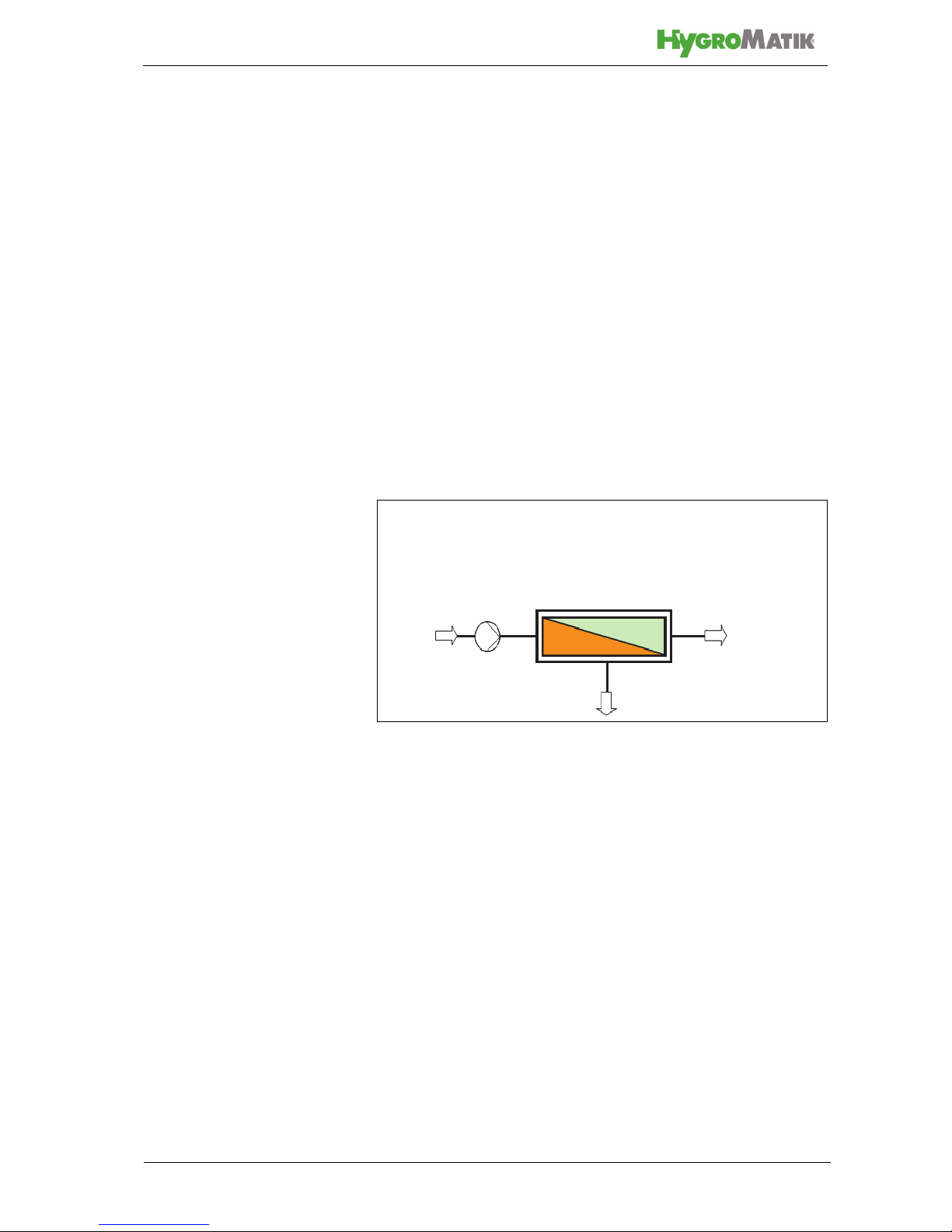
4.1 Principle of osmosis/reverse osmosis
Osmosis
Osmosis is a natural process in which water from a solution with
low salt concentration passes through a semi-permeable membrane into a solution with a higher salt concentration.
Reverse osmosis
In reverse osmosis, the natural process of osmosis is reversed
using pressure. If pressure is exerted on the side with higher
concentration than the natural osmotic pressure, pure water
from the solution diffuses through the semi-permeable membrane.
The pure water generated by a reverse osmosis system is
referred to as "permeate", the concentrated solution as "concentrate".
Fig. 1: Principle of osmosis/reverse osmosis
Concentrate recycling
To increase the flow through the membrane, part of the concentrate is returned to the raw water inlet.
4.2 Overview of components
System separator
The system separator prevents water from the water treatment
plant from flowing back into the drinking water network or being
pressurised back or sucked back (protection up to and including
fluid category 4 according to DIN EN 1717).
A dirt trap is integrated into the system separator. Particles from
the untreated water are caught here.
Inflow
Concentrate
Permeate
High pressure
pump
Raw water
 Loading...