

HygroMatik WaterLine Single, WaterLine Double Plus, WaterLine Double Operating Manual

Softener devices
WaterLine Single
WaterLine Double
WaterLine Double Plus
ÁWLSDP.ENUÈ
WLSDP.EN
Operating manual

Page 2
Warning! Hazardous Voltage: All work to be performed by trained personnel only.
All electrical installation and servicing of the electrical components of this unit to
be performed by qualified electricians only. Disconnect power supply before installation and servicing!
Copyright © HygroMatik GmbH [04.05.2015]
WL-S/D/DP EN
All rights reserved

Page 3
1. Introduction ....................................................................................................................... 5
1.1 Intended Use ..................................................................................................................... 5
1.2 Typographic markings .......................................................................................................6
1.3 Documentation .................................................................................................................. 6
2. Safety instructions ............................................................................................................ 7
2.1 General information ........................................................................................................... 7
2.2 Safety instructions for the installation and start-up of the softener device ........................ 7
2.3 Safety regulations for the operation of the softener device ............................................... 8
2.4 Safety instructions for working on electrical equipment .................................................... 9
2.5 Disposal upon disassembly ............................................................................................... 9
3. Transport ............................................................................................................................ 10
3.1 General Information ........................................................................................................... 10
3.2 Temporary storage ............................................................................................................ 10
3.3 Inspecting for correctness and completeness ................................................................... 10
3.4 Scope of delivery ............................................................................................................... 10
3.5 Packaging and return consignement ................................................................................. 10
4. Functionality and device composition ............................................................................ 11
4.1 Principle of operation ......................................................................................................... 11
4.2 WL-S and WL-D/DP device composition ........................................................................... 11
4.3 Use of optional chlorine cell ..............................................................................................14
4.4 Operating cycles ................................................................................................................ 14
4.4.1 Softening ........................................................................................................................ 14
4.4.2 Regenerate ..................................................................................................................... 14
4.5 Brine .................................................................................................................................. 17
5. Installation ......................................................................................................................... 18
5.1 Basic prequisites for operating the WaterLine softener device ......................................... 18
5.2 Selecting the correct installation location of the Waterline softener device
within the house installation scenario ................................................................................ 18
5.3 Requirements on the installation site of the WaterLine softener device ............................ 19
5.4 Set-up of the WaterLine pendulum devices WL-D/DP ...................................................... 19
5.5 Attaching the tubing for raw water and soft water ............................................................. 19
5.5.1 Prerequisites for the correct connection of the tubing on the softener device ............... 19
5.5.2 Connecting the control valve to the house water installation ......................................... 20
5.5.3 Connecting the control valve to the optional mounting block ......................................... 21
5.6 Connecting of brine tube ...................................................................................................21
5.7 Make waste water connection ........................................................................................... 21
5.8 Connecting the brine tank overflow ................................................................................... 22
6. Start-up ............................................................................................................................... 23
6.1 Operating the control valve for the first time ...................................................................... 23
6.2 Run forced regeneration ....................................................................................................24
6.3 Filling the brine tank with salt tablets ................................................................................. 24
6.4 Programming the control valve .......................................................................................... 24
6.5 Setting of the optional external blendingvalve ................................................................... 26

Page 4
7. Programming of the control valve ................................................................................... 27
7.1 General information ........................................................................................................... 27
7.2 Overview on the display and operating options for the device operator
(normal operation) ............................................................................................................. 27
7.3 Programming steps for the control valve ........................................................................... 28
7.3.1 Deactivating and re-activation of the valve lock ............................................................. 28
7.4 Settings ............................................................................................................................. 28
8. Maintenance ....................................................................................................................... 30
8.1 General information ........................................................................................................... 30
8.2 Maintenance work to be carried out by the device operator .............................................. 30
8.2.1 Daily check of proper device operation .......................................................................... 30
8.2.2 Periodical inspection ...................................................................................................... 32
8.2.3 Minor Maintenance ......................................................................................................... 32
8.3 Full maintenance ............................................................................................................... 34
8.4 Troubleshooting ................................................................................................................. 34
9. Removal from service, storage and recommissioning .................................................. 35
9.1 Removal from service ........................................................................................................ 35
9.2 Storage .............................................................................................................................. 35
9.3 Recommissioning .............................................................................................................. 35
10. Optional chlorine cell ...................................................................................................... 36
10.1 Functional description and design ................................................................................... 36
10.2 Mounting the device ........................................................................................................ 36
10.3 Setting-up the control device ........................................................................................... 37
10.4 Operating ......................................................................................................................... 37
10.5 Chlorine cell maintenance ............................................................................................... 37
10.6 Technical specifications ..................................................................................................38
10. Technical Specifications ................................................................................................ 39
11. Spare parts ....................................................................................................................... 42

Page 5
1. Introduction
Dear customer,
thank you very much for choosing a HygroMatik cabinet ion
exchanger device (softener device).
In order to operate your HygroMatik softener device safely, properly and economically please carefully study this operation manual.
Only use your HygroMatik softener device when in flawless condition as well as according to its intended use, safety and hazard
conscious and in compliance with all hints and restriction given
in this operation manual.
For any further questions please contact HygroMatik as follows:
Tel.: +
41 (0)31 932 01 11 (Main offi
ce)
Tel
.: +41 (0)31 932 01 11 (
Technical Hotline)
Fax: +41 (0)31 931 08 67
e-mail: info@badgermeter.ch
For any queries or ordering of sp
are parts please have your
device data ready!
1.1 Intended Use
The HygroMatik cabinet ion exchanger device (softener device)
is ment for the production of soft water. It may only be used
according to its intended use.
Caution: Proper use includes fulfilment of the assembly, disassembly, reassembly, start-up, operating and maintenance conditions specified by us as well as disposal measures.
Only appointed qualified staff may work on or with the system.
Persons transporting or working on or with the system must
have read and understood the relevant parts of this operating
manual, particularly the 'Safety instructions' section. Staff must
also be informed of possible hazards by the operating company.
Please keep a copy of the operating manual at the location
where the device is being used.
Any additional equipment may only be built into any parts of
the softener device with the written permission of the HygroMatik
GmbH.
WaterLine softener device utilization
• The intended case of application is the operation within the
area of drinking water supply.
• All TVO (Trinkwasserverordnung = Drinking Water Ordinance) limit and guide values must be respected. The

Page 6
iron (Fe) content limit is 0.2 mg/l, max. manganese (Mn) is
0.05 mg/l
• For use with raw water with a iron and/or manganese
content exceeding these limits, only HygroMatik WaterLine
softeners of the WL-DP family type are suited
• The softener device must not be operated outside in the
exterior
• Frost protection and humidity protection must be ensured
• Allowable environmental temperature is 5 - 40 °C with a
max. r.h. of 60 percent
• Use of a system separator according to EN 1717 (former
DIN 1998, part 4) is obligatory
• Optimum flow pressure of teh device is 4.0 bar
Please note: For protection of the softener device, a water filter according to DIN 13443-1 implemented in front of the water
intake is obligatory. Without such a filter the ion exchanger resin
might silt-up within short periods of time. Also, the control valve
might get damaged by dirt ingress.
1.2 Typographic markings
• lists with items beginning with bullets: general lists
» lists with items beginning with arrows: work or operating
steps which should or must be carried out in the specified order
installation steps which must be checked
italics figure and plan names
1.3 Documentation
Storage
Please keep this operating manual in a safe place where it is
accessible at all times. If you sell the product, be sure to include
this manual. Please contact HygroMatik if the documentation is
lost.
Language versions
This operating manual is available in different languages. Please
contact your HygroMatik dealer or HygroMatik for details.
Page 7
2. Safety instructions
2.1 General information
The safety instructions are prescribed by law. They are intended
to ensure health and safety at work and accident prevention.
Warnings and safety symbols
The following safety symbols are used in this manual to indicate
hazard and risk warnings. Please familiarise yourself with these
symbols
Caution: Failure to heed this warning may result in injury or danger to life and limb and/or damage to the device.
.
Caution:Voltage: Dangerous electrical voltage! Failure to heed
this warning may result in injury or danger to life and limb.
Indicates materials and consumables which must be handled
and/or disposed of in accordance with statutory requirements.
Please note: precedes explanations for or cross-references to
other places in the text. Also, information is marked in this way
that requires particular observance.
General safety instructions for working on the HY-EKB20
softener device
Caution: Prior to working on the softener device water supply
must be cut
Caution: The device may be under pressure. Prior to working
on the device pressure must be released.
2.2 Safety instructions for the installation and
start-up of the softener device
• Integration of the softener device into the house water
installation scenario must only be carried out by an expert
company for drinking water treatment. Local and regional
regulations must by obeyed without exemption
• The electrical connection and programming of the softener
device may only be made by trained personnel

Page 8
• Please also consider water flow pressure in your supply
situation. The allowable pressure range is 2.5 to 7.0 bar. If
pressure lies above that, a pressure reducer must be
installed
•As a protection against water damage, a gully is recommended. If not available, alternatively a water-stop may
be used
• The installation ground must be imperatively level and dry.
The device is to be placed in a way that tilting by accidental impact is not possible
• Please consider adequate distance to heat sources
• We recommend the sole use of pipes made from plastic
or stainless steel. Zinc plated water pipes are note suited
for use with zero hardness water
2.3 Safety regulations for the operation of the
softener device
General
• Any form of using the device that impaires the safety of
the device must be refrained from
• Please observe all safety and hazard signs on the device
• On functional failures switch-off the device immediately
and secure against switching on again. Clear any faults on
the spot
• After repair work operational safety must be assured by
expert staff
• Only use orignal spare parts
• All other national regulations beyond the a.m. coverage
apply without restriction for operating the device
Use by persons not entitled
This device is not intended for the use by persons (including children) with limited physical, sensoric or mental capabilities or
lacking experience and/or non-existing knowledge unless supervised by a person responsable for the user‘s safety or prior
instructions given in the use of the device. Children should be
kept an eye on to make sure that no playing with the device
happens.
Operational safety
• For your own safety regularly inspect connecting pipes
and hoses to minimize the risk of flooding
• Check the brine tank in a regular time frame to make sure
that regeneration salt is always available in sufficient
volume in order not to limit the functional capability of the
device
Page 9
• To avoid contamination by dust or pest, the brine tank
should always be closed with the appropriate cover
• Even when not in use for a longer period of time, the
device should remain switched on since hygienic regenerations are run in stand-by also
2.4 Safety instructions for working on electri-
cal equipment
Warning: Only expert personnel is permitted to work on the
electrical system and the control cabinet (if applicable).
Risk of electrical shock! Prior to working on the electrical
equipment of the softener device always cut the mains connection by unplugging the power adaptor. Make sure never to touch
electrical components with wet hands.
Switch off the system immediately if faults in the electrical
energy supply occur.
Only use original fuses with the specified amperage.
Inspect the system's electrical equipment at regular intervals.
Promptly eliminate deficiencies, such as loose connections or
melted cables. After carrying out the corresponding electrical
assembly or maintenance work, test all protective measures
used (e.g. earth resistance).
Accident prevention regulations
Caution: Heed the HSW (Health and Safety at Work) regulations
for electrical installations and equipment (VBG4/BGVA3).
By doing so you protect yourself and others from harm.
2.5 Disposal upon disassembly
The operating company is responsible for disposal of the system
parts in accordance with statutory requirements.
Page 10
3. Transport
3.1 General Information
Please note: Take care when transporting the HygroMatik sof-
tener device to prevent the device and packaging from being
damaged.
Warning: Pressure tanks are very impact sensitive und must not
be rolled.
3.2 Temporary storage
Store the device in a dry and frost-free place.
3.3 Inspecting for correctness and complete-
ness
When you receive the goods, ensure that the equipment is complete and all parts are in perfect condition.
Please note: Any transport damages and/or missing parts must
be reported immediately to the shipper or supplier.
The periods in which notification of the transport company must
occur for the purposes of identifying the damage are as follows*:
* Periods are subject to change without notice.
3.4 Scope of delivery
The following items are included in the delivery:
• Softener device (in case od a device featuring two pres-
sure tanks, the second tank is separately packaged)
• Operating manual(s)
• Accessories ordered
3.5 Packaging and return consignement
Should return consignment be necessary, please consider the
following:
• Preferably use euro pallet for packaging
• Ensure frost and humidity protection during transport
• Take care when handling pressure tanks
Transport company Time after receipt of
goods
Post no later than 24 hours
Rail 7 days at the latest
Rail and road transport
companies
4 days at the latest
Parcel services immediately

Page 11
4. Functionality and device composition
4.1 Principle of operation
The HygroMatik softener device makes use of the ion exchange
method for replacing magnesium and calcium as well as strontium and barium by natrium, thus producing so called soft water.
The device works using the concurrent process and was
designed for normal salting.
The raw water fed to the softener must be iron- and maganinefree. For use with raw water not complying to this prerequisite,
the WaterLine double softener device family WL-DP featuring a
special compatible resin filling may be used .
After the production of a set volume of soft water, regeneration
occurs on a regular base. For that purpose brine water is sucked
from the brine tank into the exchanger (pressure tank). Because
of the extremely high concentration of natrium in the brine the
hardness components bound are exchanged again with natrium.
The regeneration waste water is drained to a canal. On finishing
the regeneration cycle, the brine tank is filled-up again with
water to allow for the production of new brine.
Besides the volume based regeneration, forced regeneration is
carried out on a regular base to ensure proper hygienic conditions. Otherwise, the softener may be prone to microbial contamination if no water flow exists due to longer periods of nonusage (e.g. during holiday periods) Pre-setting for forced regeneration is 3 days. This setting may be changed by the operator.
Since the WaterLine WL-S softener device features only one
pressure tank, the device is not available for soft water production during regeneration. In contrast to this, the WaterLine softener devices WL-D and WL-DP are equipped with two pressure
tanks each, allowing for soft water production in the one tank
while - in parallel - the resin in the other tank is regenerated.
Because of this mechanism, these devices are designated as
„pendulum systems“. When the resin in the active pressure tank
is dead, the control valve switches to the other pressure tank
holding freshly regenerated resin of full capacity.
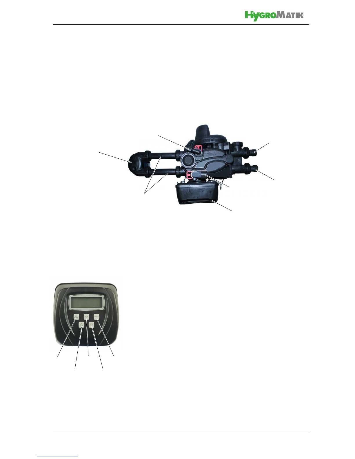
4.2 WL-S and WL-D/DP device composition
The systems are composed of a brine tank and one or two
exchangers. The resin-filled exchangers are pressure tanks
made from GRP. On top of the pressure tank (or one of the pressure tanks in case of the WaterLine WL-D/DP systems) sits the
control valve. The control valve holds a displaceable piston for
supporting all of the steps of the ion exchanger and regeneration
processes and the microprocessor-based control logic.
Control valve for WL-S, view
Control valve for WL-D/DP,
view
Page 12
Arranged in the brine tank is a stand pipe holding a riser pipe for
brine sucking. The bottom end of the riser pipe features a ball
valve that blocks sucking when the brine level has sunk accordingly. The riser pipe top end is connected to the control valve
through a brine tube.
The control valve is connected to the house water installation
either directly or via a (optionally available) mounting block
through hoses for water inlet and water outlet (optionally available water connection set including titration kit may be used).
Hose connections make use of the provided BSPT adaptors
(BSPT = British Standard Pipe Thread).
Pendulum systems feature a single control valve with the
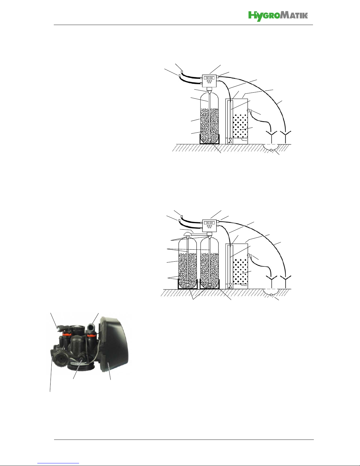
Principle design of WaterLine softener device WL-S
Control valve
Regenerations waste water connection
Soft water
connection
Brine tank
Brine tube
Raw water
connection
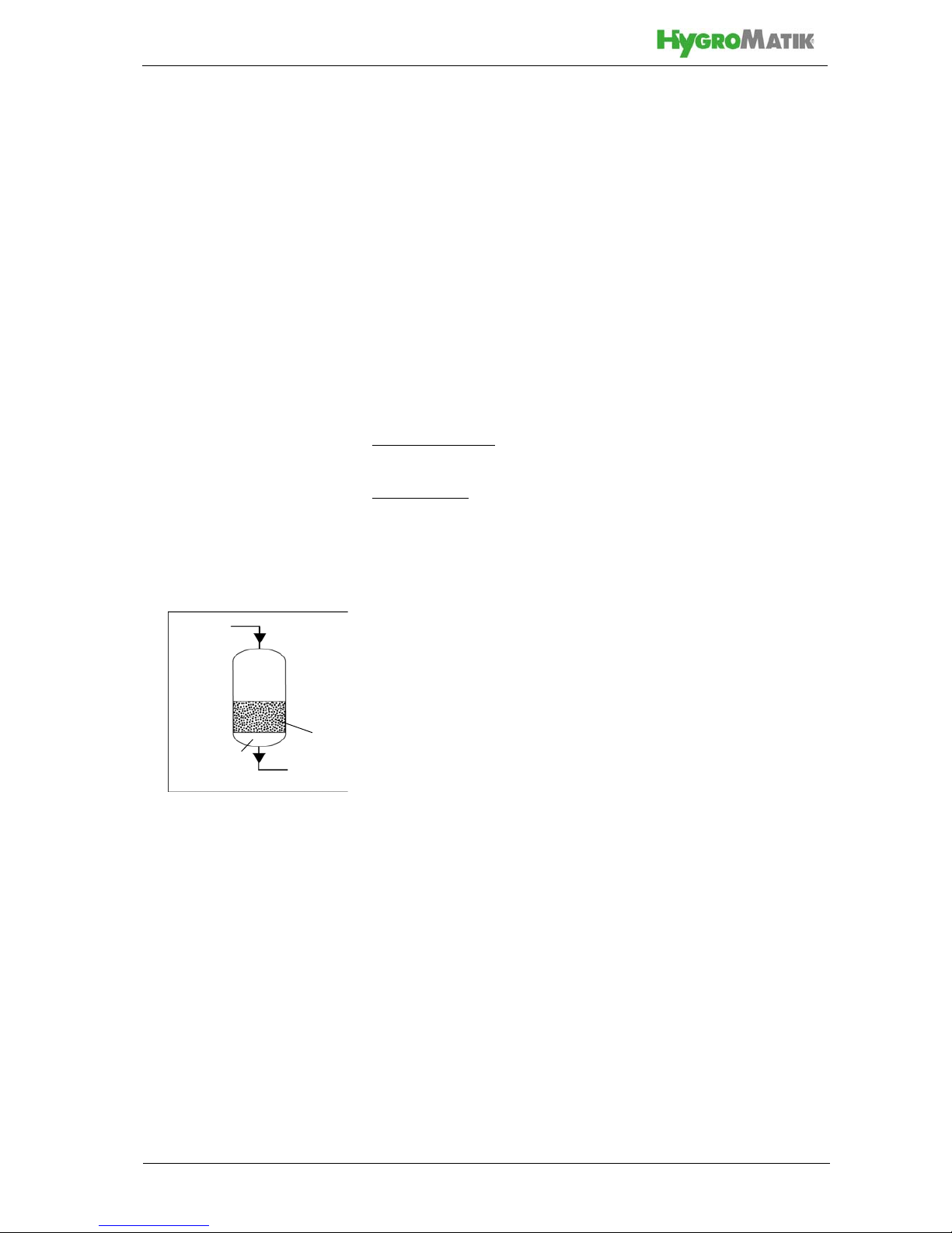
Resin filling
Riser pipe
Overflow
Floor drain
Riser pipe
w. ball valve
Pressure tank
Inserted
Riser pipe
Top nozzle
Bottom nozzle
*) Inserted floor screen only when resin capacity is 100 m3 x °dH or higher
floor screen *)
Brine
filling
Waste water
hose
Principle design of WaterLine softener device WL-D/DP
Brine tank
Brine tube
Raw water
connection
Resin filling
Riser pipes
Overflow
Floor drain
2
nd
pressure
Control valve
Riser pipe
w. ball valve
Soft water
connection
Pressure tank
Tubing
Top nozzles
Bottom nozzles
Stand pipe
Regeneration waste water connection
*) Inserted floor screen only when resin capacity is 100 m3 x °dH or higher
Inserted
floor screen *)
tank
Brine
filling
Waste water
hose
connection
Water inlet
and outlet
Wastewater
Brine tube
Blending
valve
Electronic control
with Display and
Control valve for WL-S,
connections
control panel
connection
Page 13
expanded functionality for automatic switching between pressure tanks. The tank without a control valve is connected to the
control valve on the other pressure tank via tubings for raw and
soft water.
The waste water hose is connected to a 3/4 inch elbow on the
control valve. Draining must feature an open outlet in order to
prevent microbiological contamination.
The control logic comprises a display for time-of-the-day presentation as well as the preset and programmable parameters of the
ion changer process. Operating and programming is accomplished by use of the 5 keys designated „SET CLOCK“, „NEXT“,
„REGEN“as well as „
Δ“ und „∇“ (up/down-arrows for increasing/
decreasing settings).
Control valve for WL- D/DP, connections
Brine tube
connection
Waste water
Connection head for
2
nd
pressure tank
Soft water
Raw water
Tubing for 2
nd
pressure tank
outlet
connection
Electronic control with
display and control panel
inlet
SET
CLOCK
NEXT
REGEN
Δ
∇
(Up)
(Down)
Display and control panel
of control valve for WL-S
and WL-D/P
Page 14
4.3 Use of optional chlorine cell
Periodical chlorination of the raw water feed to a softener device
is meaningful in order to fight microbiological contamination in
the exchangers and pipes by chemical means. For this purpose,
a chlorine cell may be inserted in the brine tube by use of a tpiece connector that produces active chlorine. Any excessive
chlorin is washed out with the regeneration waste water. How to
use the chlorine cell is described in a chapter of its own.
4.4 Operating cycles
Normal operation mode of the WaterLine softener devices is
„softening“ . Alternating to this (in case of single systems) or in
parallel (with double systems), then in the currently not active
exchanger, „regenerating“ is carried out. The following operating
cycles can be distinguished in detail:
Normal operation
• Softening
Regeneration
• Backwash
• Brine and Slow wash
•Rinse
• Fill (brine tank)
4.4.1 Softening
This is the normal operation mode of the WaterLine softener
device. The control valve guides raw water into the pressure
tank filled with exchanger resin. Raw water flows top down
through the resin while the resin absorbes magnesium and calcium ions, exchanging them with sodium ions. By this mechanism, softened water is generated. The product water enters the
rise pipe in the pressure tank through the bottom nozzle and is
subsequently propagated to the control valve and, finally, to the
consumer through the product water pipe.
4.4.2 Regenerate
Since the exchange capacity of the resin is exhausted after a
certain volume of soft water produced, regeneration is required
on a regular time frame. For this purpose, NaCl brine is used
that is produced by dissolving salt tablets in the brine tank.
Regeneration point of time is determined by the control valve. To
enable this, „soft water capacity“ with respect to the Waterline
device capacity and local raw water hardness must be programmed into the the control valve logic. On reaching the
threshold set, automatic regeneration will result. The number of
regeneration occurences is only restricted by resin life time.
Softening
Soft water
Raw water
resin
Exchanger
 Loading...