

HygroMatik MiniSteam, MiniSteam MS 5, MiniSteam MS 10 Series Manual

Electrode Steam Humidifier
MiniSteam
ÁMS.CSA^È
MS.CSA
E-8881706
IMPORTANT: READ AND SAVE
THESE INSTRUCTIONS
Manual
Certain computer programs contained in this product [or device] were developed by HygroMatik
GmbH ("the Work(s)").
© Copyright HygroMatik GmbH
MiniSteam CSA [01.03.2017]
Current version of this manual can be found at: www.hygromatik.co.uk
All rights reserved.
HygroMatik GmbH grants the legal user of this product [or device] the right to use the Work(s)
solely within the scope of the legitimate operation of the product [or device]. No other right is
granted under this licence. In particular and without prejudice to the generality of the foregoing,
the Work(s) may not be used, sold, licensed, transferred, copied or reproduced in whole or in
part or in any manner or form other than as expressly granted here without the prior written consent of HygroMatik GmbH.
Information in this manual is subject to change or alteration without prior notice.
Risk of electrical shock!
Hazardous electrical high voltage!
All electrical work to be performed by certified expert staff (electricians or expert personnel with
eqivalent training) only. Disconnect power supply prior to work start!
Page 2

1. Introduction ....................................................................................................................... 5
1.1 Typographic Distinctions ...................................................................................................5
1.2 Documentation .................................................................................................................. 5
1.3 Symbols in Use ................................................................................................................. 6
1.3.1 Specific Symbols related to Safety Instructions ............................................................. 6
1.3.2 General Symbols ............................................................................................................ 6
1.4 Intended Use ..................................................................................................................... 6
2. Safety Instructions ............................................................................................................ 8
2.1 Guidelines for Safe Operation ........................................................................................... 8
2.1.1 General ........................................................................................................................... 8
2.1.2 Unit control ..................................................................................................................... 8
2.1.3 Unit operation ................................................................................................................. 8
2.1.4 Mounting, maintenance, repair and dismantling of the unit ............................................ 9
2.1.5 Electrical ......................................................................................................................... 9
3. Transport ............................................................................................................................ 10
3.1 Overview ........................................................................................................................... 10
3.2 Carton outer Size and Weight ........................................................................................... 10
3.3 Packing .............................................................................................................................. 11
3.4 Interim Storage .................................................................................................................. 11
3.5 Check for Complete and Correct Delivery of Goods ......................................................... 11
3.6 Included in the Delivery ..................................................................................................... 11
4. Functional description and device composition ............................................................ 12
4.1 Mode of operation ............................................................................................................. 12
4.2 Structure and operation of the device ............................................................................... 12
4.1.1 Fitting measures ............................................................................................................. 16
4.2 Unit Installation Check ....................................................................................................... 17
4.3 Unit Dimensions ................................................................................................................ 18
5. Water Installation .............................................................................................................. 19
5.1 Operation with Softened Water ......................................................................................... 20
5.2 Water Supply ..................................................................................................................... 21
5.3 Water discharge ................................................................................................................ 22
5.4 Water Installation Checklist ...............................................................................................23
6. Electrical Connection ........................................................................................................ 24
6.1 Electrical Installation .......................................................................................................... 24
6.2 Cable Connections ............................................................................................................ 26
6.3 Safety Interlock .................................................................................................................. 27
6.4 Wiring Diagram .................................................................................................................. 27
6.5 Electrical Installation Checklist ..........................................................................................27
7. Commissioning ................................................................................................................. 29
8. Maintenance ....................................................................................................................... 30
8.1 Maintenance Work ............................................................................................................ 31
8.2 Access Electrical Enclosure .............................................................................................. 32
8.3 Removing and Cleaning the Steam Cylinder .................................................................... 32
Page 3

8.4 Electrode wear .................................................................................................................. 36
8.4.1 Original Electrode Lengths ............................................................................................. 37
8.4.2 Uneven Electrode Lengths ............................................................................................. 37
8.5 Replacing Electrodes ........................................................................................................ 37
8.6 Cleaning the Blow- Down Pump ........................................................................................ 40
8.7 Cleaning the Water Inlet Solenoid Valve ........................................................................... 41
8.8 Checking Cable Connections and Electrode Cables ......................................................... 42
8.9 Checking Hoses ................................................................................................................ 42
8.10 Checking Operation ......................................................................................................... 42
9. Dismantling ........................................................................................................................ 43
10. CSA Certificate of Compliance ...................................................................................... 44
11. Fax Form - Order for spare parts ................................................................................... 47
12. Spare Parts ...................................................................................................................... 48
13. Technical Data ................................................................................................................. 50
14. Exploded View ................................................................................................................. 51
15. View of housing ............................................................................................................... 52
Page 4

1. Introduction
Dear Customer,
Thank you for choosing a HygroMatik steam humidifier.
HygroMatik steam humidifiers represent the latest in humidification technology.
In order to operate your HygroMatik steam humidifier safely, properly and efficiently, please read these operating instructions.
Employ your steam humidifier only in sound condition and as
directed. Consider potential hazards and safety issues and follow all the recommendations in these instructions.
If you have additional questions, please contact us:
Tel.: +49-(0)4193 / 895-0 (Main Number)
Tel.: +49-(0)4193 / 895-293 (Technical Support Hotline)
Fax: +49-(0)4193 / 895-33
e-mail: hotline@HygroMatik.de
For all technical questions or spare parts orders, please be prepared to provide unit type and serial number (see name plate on
the unit).
1.1 Typographic Distinctions
• preceded by a bullet: general specifications
» preceded by an arrow: Procedures for servicing or
maintenance which should or must be performed in the
indicated order
Installation step which must be checked off
italics Terms used with graphics or drawings
1.2 Documentation
Retention
Please retain these operating instructions in a secure, always
accessible location. If the product is resold, turn the documentation over to the new operator. If the documentation is lost, please
contact HygroMatik.
Versions in Other Languages
These operating instructions are available in several languages.
If interested, please contact your expert dealer.
Page 5
Please note
1.3 Symbols in Use
1.3.1 Specific Symbols related to Safety Instructions
According to ANSI Z535.6 the following signal words are used
within this document:
DANGER indicates a hazardous situation which, if not avoided,
will result in death or serious injury.
WARNING indicates a hazardous situation which, if not avoided,
could result in death or serious injury.
CAUTION indicates a hazardous situation which, if not avoided,
could result in minor or moderate injury.
NOTICE is used to address practices not related to physical
injury.
1.3.2 General Symbols
This symbol is used whenever a situation requires special attention beyond the scope of safety instructions.
1.4 Intended Use
The HygroMatik steamgenerator serves for steam production
based on various water qualities or partially softened water
(valid for all of the HygroMatik humidifier models). With the HeaterLine, HeaterCompact/Kit and HeaterSlim familiy of products,
also fully desalinated water/cleaned condensate may be used.
Only use supply water featuring a conductivity of 125 to
1250 µS/cm.
Page 6
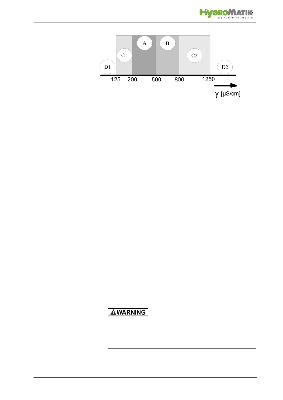
D1: Lower threshold
C1: Range of reduced conductivity (adjustments recommended)
A: Normal tap water
B: Range of heightened conductivity
C2: Range of high conductivity (adjustments recommended)
D2: Upper threshold
Proper usage also comprises the adherence to the conditions
specified by HygroMatik for:
• installation
• dismantling
• reassembly
• commissioning
• operation
• maintenance
• disposal.
Only qualified and authorised personnel may operate the unit.
Persons transporting or working on the unit must have read and
understood the corresponding parts of the Operation and Maintenance Instructions and especially the chapter 2. „Safety
Notes“. Additionally, operating personnel must be informed of
any possible dangers. You should place a copy of the Operation
and Maintenance Instructions at the unit‘s operational location
(or near the unit).
By construction, HygroMatik steam humidifiers are not qualified for exterior application.
Risk of scalding!
Steam with a temperature of up to 212 °F is produced.
Do not inhalate steam directly in order to avoid respiratory
damage!
Page 7
2. Safety Instructions
These safety instructions are required by law. They promote
workplace safety and accident prevention.
2.1 Guidelines for Safe Operation
2.1.1 General
Comply with the accident prevention regulation „DGUV Regulation 3“ to prevent injury to yourself and others. Beyond that,
national regulations apply without restrictions.
2.1.2 Unit control
Do not perform any work which compromises the safety of the
unit. Obey all safety notes and warnings present on the unit.
In case of a malfunction or electrical power supply disruption,
switch off the unit immediately and prevent from restart. Repair
malfunctions promptly.
Restricted use
This unit is not designed for the use by persons (also children)
with limited physical, sensory and mental abilities - or without
knowledge and experience - unless they are supervised or trained by a person, who is responsible for their safety.
Supervise children in order to ensure that they will not play with
the unit.
2.1.3 Unit operation
Risk of scalding!
In case of leaking or defective components, hot steam may exit
in an uncontrolled manner.
Switch off unit immediately.
Risk of material damage!
The unit may be damaged if switched on repeatedly following a
malfunction without prior repair.
Rectify defects in return!
• The unit must not be operated on a DC power supply
• The unit may only be used connected to a steam pipe that
safely transports the steam (not valid device type MiniSteam)
Page 8
• Regularly check that all safety and monitoring devices are
functioning normally
• Do not remove or disable safety devices
2.1.4 Mounting, maintenance, repair and dismantling
of the unit
The HygroMatik steam humidifier is IP20 protected. Make sure
that the unit is not object to dripping water in the mounting location.
When installation is made in a room without a drain, safety precautions must be taken in order for to shut off the humidifier‘s
water supply in event of a leak.
• Use genuine spare parts only
• After any repair work, have qualified personnel check the
safe operation of the unit
• Attaching or installing of additional components is per-
mitted only with the written consent of the manufacturer
• The operator is responsible for the disposal of unit components as required by law
2.1.5 Electrical
Risk of electrical shock!
Hazardous electrical high voltage!
Any work on the electrical system must only be performed by
qualified personnel.
Disconnect unit components from electrical power supply prior
to work.
After electrical installation or repair work, test all safety mechanisms (such as grounding resistance).
Only use original fuses with the appropriate amperage rating.
Regularly check the unit‘s electrical equipment. Promptly repair
any damage such as loose connections or burned wiring.
Responsibility for intrinsically safe installation of the HygroMatik
steam humififiers (steam generators) is incumbent on the installing specialist company.
Page 9

Please note
3. Transport
3.1 Overview
Proceed carefully when transporting the steam humidifier in
order to prevent damage due to stress or careless loading and
unloading.
3.2 Carton outer Size and Weight
HyLine:
Type* Height
[cm]/[inch]
HY05- 08 58/22.8 56/22.0 32/12.6 16/35.3
HY13- 17 75/29.5 63/24.8 37/15.6 24/52.9
HY23 75/29.5 63/24.8 37/15.6 25/55.1
HY30 81/31.9 67/26.4 41/16.1 33/72.8
HY45 88/34.6 76/29.9 48/18.9 46/101.4
HY60 80/31.5 104/40.9 41/16.1 54/119.0
HY90- 116 90/35.4 117/46.1 48/18.9 77/169.8
CompactLine:
Type* Height
[cm]/[inch]
C01 46/18.1 45/17.7 26/10.2 11/24.3
C02 48/18.9 44/17.3 31/12.2 12/26.5
C06 52/20.4 50/19.7 28/11.0 13/28.7
C10 58/22.8 51/20.1 31/12.2 14/30.9
C17 75/29.5 54/21.3 37/14.6 22/48.5
C22 75/29.5 54/21.3 37/14.6 22/48.5
C30 75/29.5 58/22.8 37/14.6 23/50.7
C45 81/33.1 63/24.8 41/16.1 25/55.1
C58 90/35.4 72/28.3 48/18.2 36/79.4
Width [cm]/
Width
[cm]/[inch]
[inch]
Depth
[cm]/[inch]
Depth [cm/
[inch]]
Weight
[kg]/[lbs]
Weight [kg]
MiniSteam:
Type**Height
[cm]/[inch]
MS 5 59/23.2 48/18.9 28/11.0 13/28.7
MS 10 68/26.8 51/20.1 31/12.2 15/33.1
* Dimensions and weights may vary slightly.
Page 10
Width [cm]/
[inch]
Depth [cm]/
[inch]
Weight[kg]
Please note
Please note
3.3 Packing
Notice the symbols affixed to the packing box.
3.4 Interim Storage
Store the unit in a dry place and protect against frost.
3.5 Check for Complete and Correct Delivery of
Goods
Upon receipt of the unit, confirm that:
• the type and serial number on the name plate match
those specified in the order and delivery documents
and
• the equipment is complete and all parts are in perfect
condition
In case of damage during shipment or missing parts, immediately notify the carrier or supplier in writing.
Time limits for filing freight claims with shipping companies are*:
Shipping Companies After Receipt of Goods
Carriers no later than 4 days
Parcel Service immediately
* Time limits for some services subject to change.
3.6 Included in the Delivery
The delivery includes:
• Unit of the selected humidifier type including selected
control.
• Water installation hose 0,6m/23.6inch, 3/4".
• Mounting set with anchors and screws. For HyLine
types HY45 to HY116, extra mounting bar.
• Operating Instructions for the unit and the control.
• Ordered accessories (steam manifold, steam hose,
condensate hose, etc.).
• Maintenance o-ring set for steam cylinder.
Page 11

4. Functional description and device compo-
sition
4.1 Mode of operation
The HygroMatik steam humidifier utilizes the conductivity normally present in tap water for steam production. Electrodes
inside an enclosed steam cylinder are immersed directly into the
tap water. They are connected to the alternating current.
The conductivity of the water generates an electric current
between the electrodes. In this way, the electric power supplied
is converted directly into heat without energy loss.
The amperage is a function of the available voltage, the
immersed electrode surface area, the average distance between
the electrodes and the water conductivity. The steam output of
the humidifier is determined by electric power usage, which is
regulated by increasing or decreasing the immersed surface
area of the electrodes.
Concurrently, a self-regulating control keeps conductivity within
a specified range.
The steam produced has a temperature of about 100°C/212°F
with minimal excess pressure ("pressureless steam"). It is
largely free of minerals and germ-free. Mineral deposits typically
remain behind in the cylinder.
4.2 Structure and operation of the device
When the controller specifies an increase in humidity, the main
contactor is switched on and the electrodes (48) are supplied
with power. The water inlet solenoid valve (25) feeds water into
the steam cylinder (16+19).
As soon as the electrodes are immersed, the current begins to
flow. The water is now heated. When the pre-selected output is
reached, the control turns off the solenoid valve and interrupts
the water supply.
After a short heating up period, the water between the electrodes begins to boil and vaporize. The vaporization lowers the
water level (W) in the steam cylinder, reducing the output provided. The inlet solenoid valve, equipped with a fine mesh filter,
intermittently admits fresh water.
Humidifier power usage is continuously monitored. With a cold
start-up, the nominal current increases to 12 % in order to
achieve quick-start output parameters. This activates the electronic overflow limiter which causes a partial draining of the cylinder. This reduces the immersed surface area of the electrodes,
lowering power usage.
Page 12
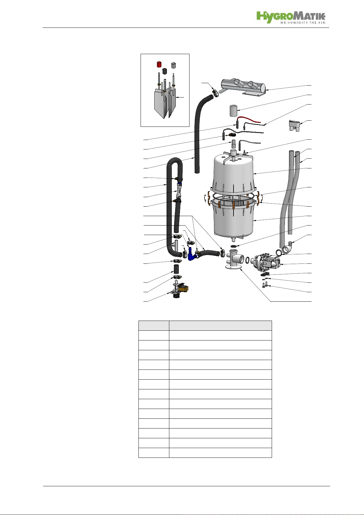
32
42
20
12
25
15
26
21
24
39
11
37
6
18
43
44
49
1
8
17
4
58
22
22
22
22
22
2
10
14
16
19
48
35
31
30
38
22
22
22
Please also see Section „Exploded View“.
Location Designation
1 steam nozzle
Page 13
6 vent pipe
10 max. water level sensor electrode
14 water drain, discharge
16 top part of steam cylinder
17 o-ring cylinder flange
18 cylinder flange and o-ring
19 lower part of cylinder
25 solenoid valve water inlet
32 blow-down pump
35 o-ring
37 cylinder base
48 electrodes

The concentration of dissolved salts increases over time, which
can lead to a rise in the conductivity of the water. If this continues, conductivity may increase until a short circuit occurs. This
could damage the unit, but in any case would significantly
reduce the life span of the electrodes.
For this reason, regular, periodic blow-downs of some of the
concentrated water are very important. Following this procedure
as recommended provides stable cylinder water conductivity as
well as minimal water loss for the expected service life of the cylinder.
Water blow-down is performed by a blow-down pump (32). The
functioning of the blow-down pump is continuously monitored
during operation. If the pump is damaged, the steam humidifier
shuts down.
With normal water quality, the blow-down loss rate is between
7% and 15% of the amount of steam produced. The steam cylinder requires complete drainage every 3-8 days, regardless of
the water quality.
Mineral deposits settle in the open area below the electrodes
and are removed through periodic maintenance. The blow-down
pump itself has wide openings and can flush out smaller pieces
of mineral deposit. This extends the service life of the unit and
reduces the required maintenance interval.
During blow-downs, water flows from the pump into the drainage
system.
A sensor electrode (10) monitors the maximum
water capacity
of the cylinder. When the water level reaches the sensor electrode, the water supply is interrupted. This can occur when the
water has low conductivity or when the electrodes are worn out.
In the case of low water conductivity, however, this state usually
lasts only a short time. The built-in control and the large area
electrodes combine to produce a rapid rise in conductivity by
increasing the concentration of the water.
The steam cylinder consists of a top (16) and lower (19) part
joined with a cylinder flange. The seal between the cylinder and
cylinder base (37), as well as between the top and lower part of
the cylinder, is maintained using an o-ring (35).
Risk of skin burns!
During operation and for at least 10 mins afterwards the steam
nozzle is hot!
Do not touch!
Page 14

Risk of scalding!
During operation hot steam discharges from the nozzle.
Avoid direct contact with the visible steam cloud.
Due to foaming within the cylinder caused by contamination hot
water may trickle from the nozzle.
Keep clear!
Rotating parts!
During operation the cross-flow fan rotates.
Do not touch or block the fan during operation.
Page 15
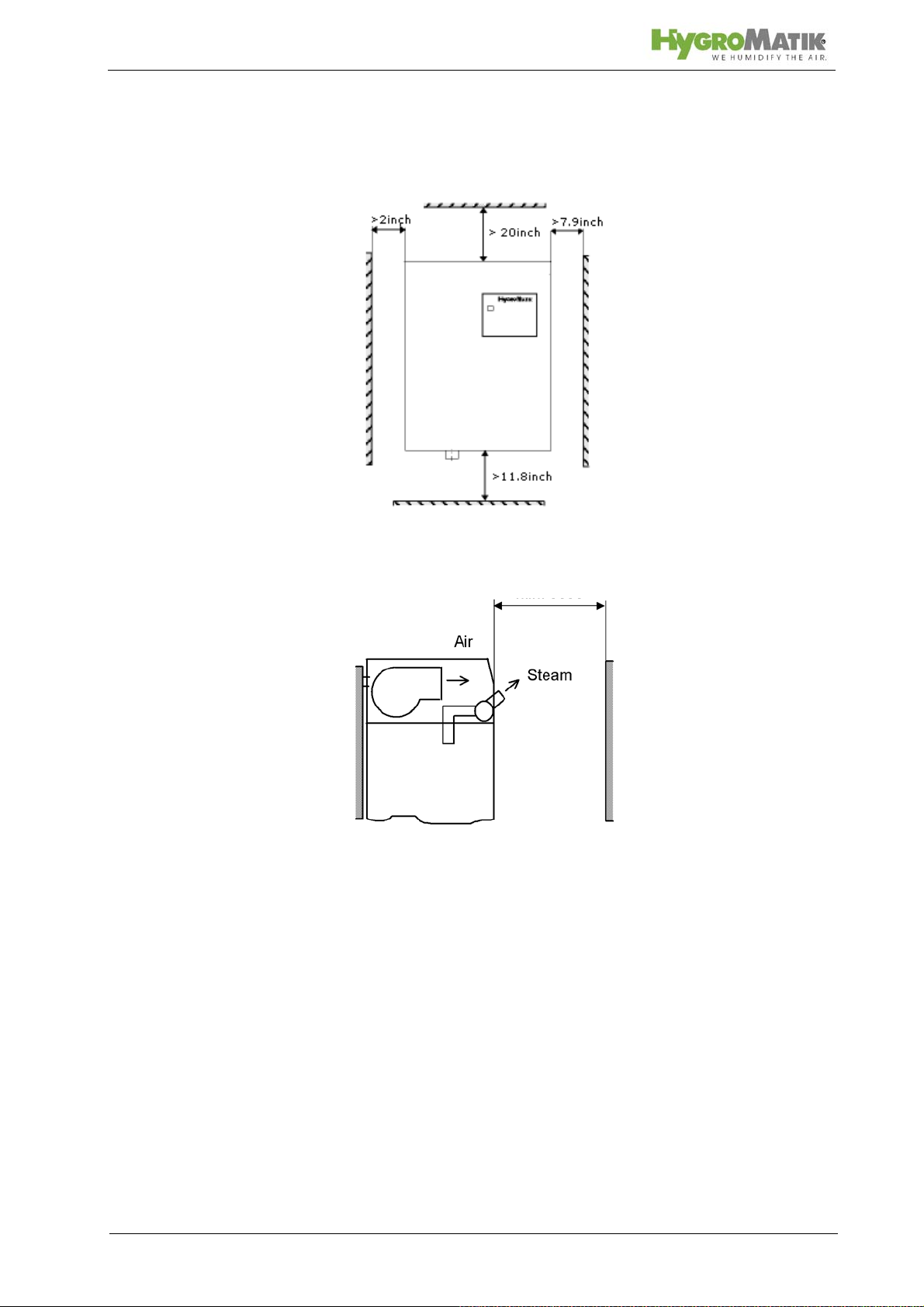
> 300mm/
> 500mm/
> 200mm/
> 50mm/
> 3000mm/118inch
4.1.1 Fitting measures
Wall Distances [mm/inch]
Page 16
Please note
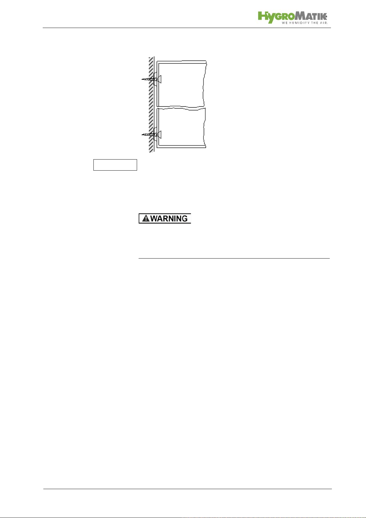
Wall Mounting
The steam humidifier must be installed vertically in order to function properly. Positioning should be such that draught effects are
avoided. The minimum mounting height is 0.15m/ 5.9 inch above
floor level. However, in order to avoid the risk of scalding a
mounting height of 2m/79 inch is recommended.
Risk of foot injuries!
Unit can drop during mounting by a single person.
Helping hand of a second person is required.
» Position the steam humidifier in the planned location,
adjust with spirit level and mark position of hanging
bolts. See also "Equipment Dimensions".
» Hang the unit onto bolts screwed into the marked posi-
tion.
4.2 Unit Installation Check
Please check the installation using the following list:
Does unit hang vertically?
Are wall distances to the unit within the range
Is the unit installed in such a way that draught effects
are avoided?
Are all bolts and clamps tightened?
Page 17
 Loading...