

HygroMatik HyLine User Manual
Electrode Steam HumidifierElectrode Steam Humidifier
Manual
Copyright HygroMatik GmbH
HyLine, March 2010
Information in this manual is subject to change or alteration without prior notice.
A Word about Water Quality
The mode of operation of all electrode steam humidifiers is based on the fact that water contains
minerals and is therefore conductive.
• "normal" tap water is ideal.
• but what is "normal" tap water exactly?
Users of HygroMatik units in the most diverse areas consider their tap water "normal."
HygroMatik typically defines "normal" as feed water with a conductivity between 200 and 500 µS/
cm (microSiemens per centimeter) at 15° C.
Some areas, however, are supp lied with tap water whose quality is outside the paramet ers specified by HygroMatik. If the HygroMatik steam humidifier's control is not adjusted correctly in these
areas, the unit cannot perform optimally. For example, the electrodes could wear out particularly
quickly or the steam production could be too low.
The operational parameters set by HygroMatik in the factory are intended for normal tap water.
However, they can very easily be reprogrammed to fit the special requirements of a particular
area. In addition, it is possible to install a plastic star in the cylinder in order to increase the life
span of the electrodes or to provide a flushing mechanism to extend maintenance intervals.
Because of this you should monitor your new unit during initial operation. Make sure that it has
been properly installed and is operating to your satisfaction.
Consult your HygroMatik specialists. We will test the quality of your water and advise you on
installation and initial operation. Your HygroMatik steam humidifier will be carefully adapted to
your particular application.
Warning, Hazardous Voltage: All work to be performed by trained personnel only.
All electrical installation and servicing of the electrical components of this unit to be
performed by qualified electricians only. Disconnect power supply before inst allation
and servicing!
Page 2

1. Introduction ....................................................................................................................... 5
1.1 Directions for Use ..............................................................................................................5
1.2 Typographic Distinctions ...................................................................................................6
1.3 Documentation ..................................................................................................................7
2. Safety Notes ....................................................................................................................... 8
2.1 Overview ...........................................................................................................................8
2.2 Guidelines for Safe Operation ...........................................................................................8
2.3 Disposal after Dismantling .................................................................................................9
3. Transport ............................................................................................................................ 10
3.1 Overview ...........................................................................................................................10
3.2 Carton outer Size and Weight ...........................................................................................10
3.3 Packing ..............................................................................................................................11
3.4 Interim Storage ..................................................................................................................11
3.5 Check for Complete and Correct Delivery of Goods .........................................................11
3.6 Included in the Delivery .....................................................................................................11
4. Operation and Installation ................................................................................................ 12
4.1 Mode of Operation .............................................................................................................12
4.2 Installation and Operation .................................................................................................12
5. Installation ......................................................................................................................... 15
5.1 Steam Humidifier Operating Environment ......................................................................... 15
5.1.1 Fitting measures .............................................................................................................16
5.1.2 Unit Dimensions HY05-HY45 ......................................................................................... 18
5.1.3 Unit Dimensions HY60-HY116 ....................................................................................... 19
5.2 Fan Unit (optional) ............................................................................................................. 20
5.2.1 Fan Unit Type VG ...........................................................................................................20
5.2.2 Fan Unit Cover ............................................................................................................... 21
5.3 Absorption Distance BN ....................................................................................................22
5.3.1 Determining the Absorption Distance ............................................................................. 22
5.3.2 Absorption Distance Nomogram .................................................................................... 24
5.4 Steam Manifold .................................................................................................................25
5.4.1 Notes on Installation ....................................................................................................... 25
5.5 Steam Line ........................................................................................................................ 29
5.6 Cover Plate ........................................................................................................................30
5.7 Drill Pattern ........................................................................................................................31
5.8 Condensate Hose ..............................................................................................................33
5.9 Types of Installation ..........................................................................................................33
5.10 Steam Solenoid Valves ...................................................................................................35
5.11 Unit Installation Check ..................................................................................................... 35
6. Water Installation .............................................................................................................. 36
6.1 Operation with Softened Water .........................................................................................36
6.2 Water Supply .....................................................................................................................37
Page 3

6.3 Water discharge ................................................................................................................ 38
6.4 Water Installation Check ...................................................................................................39
7. Electrical Connection ........................................................................................................ 40
7.1 Electrical Installation .......................................................................................................... 40
7.2 Cable Connections ............................................................................................................ 42
7.3 Fan Unit .............................................................................................................................43
7.4 Safety Interlock .................................................................................................................. 44
7.5 Wiring Diagram .................................................................................................................. 44
7.6 Electrical Installation Checklist ..........................................................................................44
8. Commissioning ................................................................................................................. 45
9. Maintenance ....................................................................................................................... 46
9.1 Maintenance Work ............................................................................................................46
9.2 Access Electrical Enclosure .............................................................................................. 47
9.3 Removing and Cleaning the Steam Cylinder .................................................................... 48
9.4 Electrode wear ..................................................................................................................53
9.4.1 Original Electrode Lengths .............................................................................................54
9.4.2 Uneven Electrode Lengths .............................................................................................54
9.5 Replacing Electrodes ........................................................................................................54
9.6 Cleaning the Blow- Down Pump ........................................................................................56
9.7 Cleaning the Water Inlet Solenoid Valve ........................................................................... 57
9.8 Checking Cable Connections and Electrode Cables .........................................................57
9.9 Checking Hoses ................................................................................................................58
9.10 Checking Operation ......................................................................................................... 58
9.11 Dismantling ......................................................................................................................58
10. EC-Declaration of Conformity ........................................................................................ 59
11. Spare Parts ...................................................................................................................... 60
12. Fax Form - Order for spare parts ................................................................................... 65
13. Technical Specification .................................................................................................. 66
14. Exploded View ................................................................................................................. 68
15. View of housing ............................................................................................................... 69
Page 4

1. Introduction
Dear Customer,
Thank you for choosing a steam humidifier.
HygroMatik steam humidifiers represent the latest in humidifica-
tion technology.
They will impress you with their safety, ease of use and econom-
ical operation.
In order to operate your HygroMatik steam humidifier safely,
properly and efficiently, please read these operatin g instructions.
Employ your steam humidifier only in sound condition and as
directed. Consider potential hazards and safety issues and follow all the recommendations in these instructions.
If you have additional questions, please contact us:
Tel.: +49-(0)4193 / 895-0 (Main Number)
Tel.: +49-(0)4193 / 895-293 (Technical Support Hotline)
Fax: +49-(0)4193 / 895-33
e-mail: hot1@HygroMatik.de
For all technical questions or spare parts orders, please be prepared to provide unit type and serial number (see name plate on
the unit).
1.1 Directions for Use
The HygroMatik steam humidifier is intended for steam production.
Proper usage also entails following HygroMatik's instructions for
installation, dismantling, reassembly, initial operation and operation and maintenance, as well as disposal procedures.
Only qualified, authorized personnel may operate or service the
unit. Workers who transport or service the unit must have read
and understood the relevant sections of the operating instructions, especially the section "Safety Notes." In addition, staff
must receive safety training about potential hazards from the
operator. Place a copy of the operating instructions at the location where the unit is operated.
Page 5
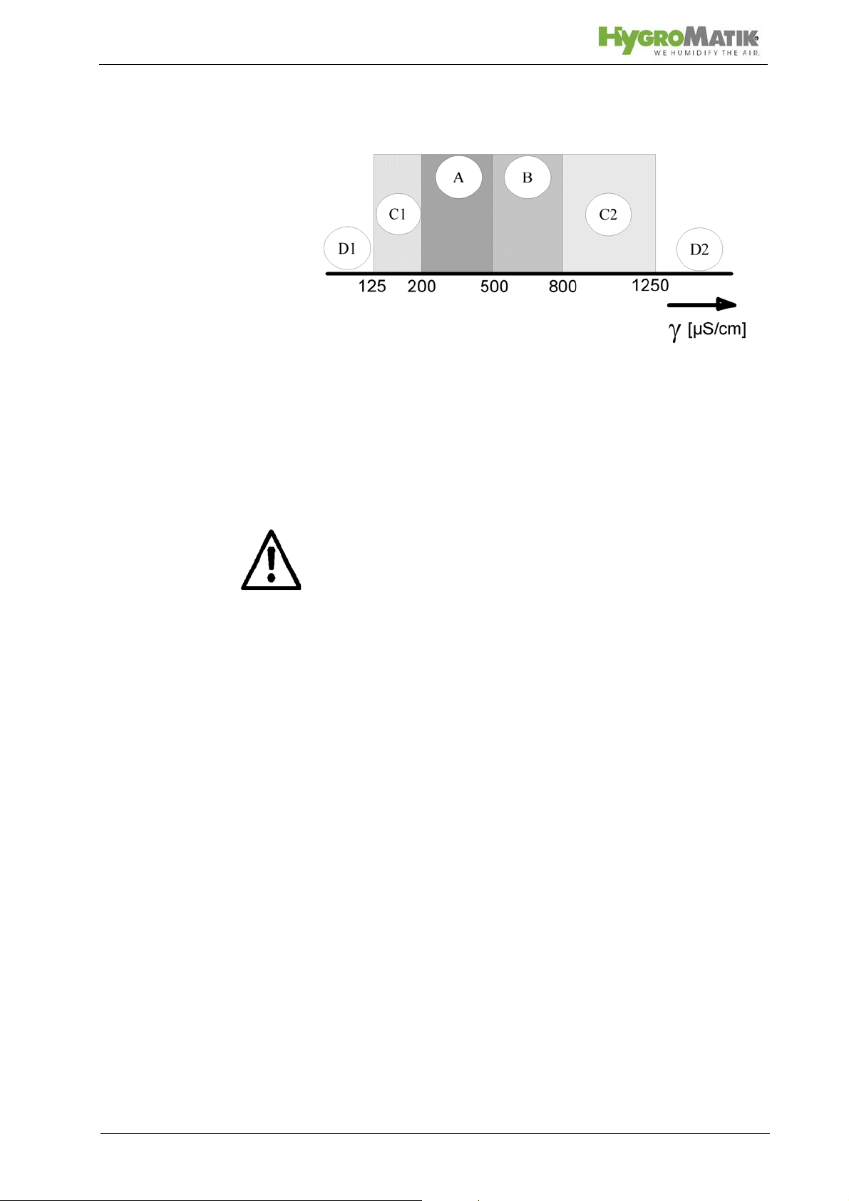
Use feed water with a conductivity between 125 and 1250 µS/
cm only
D1: Lower threshold
C1: Range of reduced conductivity (adjustments recommend ed)
A: Normal tap water
B: Range of heightened conductivity
C2: Range of high conductivity (adjustments recommended)
D2: Upper threshold
Warning: HygroMatik steam humidifiers emit steam with a temperature of 100° C. The steam may not be inhaled directly.
The HygroMatik Steam Humidifier is not designed for out door fitting
1.2 Typographic Distinctions
preceded by a bullet: general specifications.
» preceded by an arrow: Procedures for servicing or
maintenance which should or must be performed in the
indicated order.
Installation step which must be checked off.
italics Terms used with graphics or drawings..
Page 6

1.3 Documentation
Retention
Please retain these operating instructions in a secure, always
accessible location. If the product is resold, turn the documentation over to the new operator . If the document ation is lost, please
contact HygroMatik.
Versions in Other Languages
These operating instructions are available in several languages.
If interested, please contact HygroMatik or your HygroMatik
dealer.
Page 7
2. Safety Notes
2.1 Overview
These safety notes are required by law. They promote workplace safety and accident prevention.
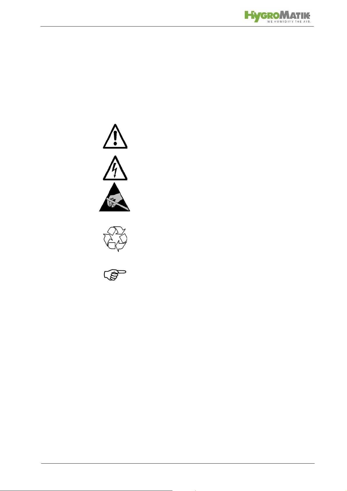
Warnings and Safety Symbols
The safety symbols below identify sections containing warnings
about hazards or potential dangers. Please familiarize yourself
with these symbols.
Warning: Failure to observe this warning may result in serious
injury or death and/or damage to the unit.
Danger, Hazardous Voltage: Hazardous electrical current!
Failure to observe this warning may result in injury or even seri-
ous injury or death.
Warning: Failure to follow these instructions may result in dam-
age to the unit due to electrostatic discharge. The electronic
components of the humidifier control are very sensitive to electrostatic discharges. In order to safeguard these components
during installation and servicing, steps must be taken to protect
against ESD.
Reminder: Materials and consumables must be handled and/or
disposed of as required by law.
Note: Appears before explanations or cross-references which
refer to other sections of the operating instructions.
2.2 Guidelines for Safe Operation
Overview
Obey all safety notes and warnings present on the unit. In case
of a malfunction, switch off the unit immediately and prevent a
restart. Repair malfunctions promptly. After any repair work,
have qualified personnel check the safe operation of the unit.
Use original spare parts only. Additional national safety regulations also fully apply to the operation of this unit.
This unit is not designed for the use by persons (also children)
with limited physical, sensory and mental abilities - or without
knowledge and experience. Unless they are supervised or
trained by a person, who is responsible for their safety.
Supervise children in order to ensure that they will not play with
the unit.
The unit is only allowed to work with connected steam hose that
safely leads the steam.
Page 8
HygroMatik steam humidifiers are IP20-protected. Make sure
that the unit is protected from drips in its installed location.
Installing a humidifier in a room without water discharge requires
safety devices to protect against water leakages.
Accident Prevention Regulations
Comply with the accident prevention regulationAccident Prevention Regulation Electrical Systems and Equipment to prevent
injury to yourself and others.
Operation of the Unit:
Do not perform any work which compromises the safety of the
unit. Regularly check that all safety and monitoring devices are
functioning normally. Do not remove or disable safety devices.
Installation, Di smantling, Maintenance and Re pair of the
Unit:
Disconnect unit components from power supply prior to maintenance or repair work.
Attaching or installing additional components is permitted only
with the written consent of the manufacturer.
Electrical
Work on the electrical system must be performed by qualified
personnel.
Disconnect unit components from power supply prior to work.
It is not allowed to connect the unit to DC voltage supply.
In case of a malfunction in the electrical power supply, switch off
the unit immediately. Use only original fuses with the appropriate
amperage rating. Regularly check the unit's electrical equipment. Promptly repair any damage, such as loose connections,
burned wiring or defective electrical insulation. After proper e lectrical installation or repair, test all safety mechanisms (such as
grounding resistance).
2.3 Disposal after Dismantling
Note: The operator is responsible for the disposal of unit compo-
nents as required by law.
Page 9
3. Transport
3.1 Overview
Note: Proceed carefully when transporting the steam humidifier
in order to prevent damage due to stress or careless loading and
unloading.
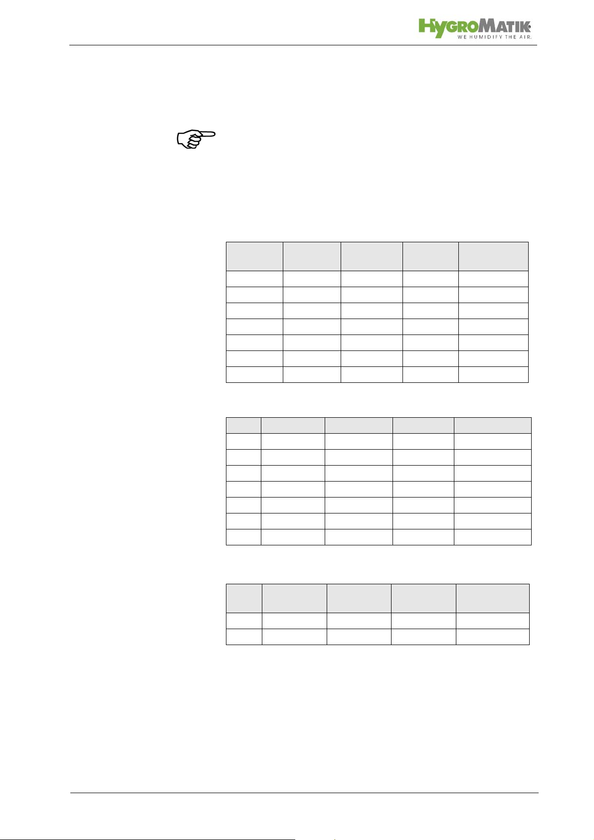
3.2 Carton outer Size and Weight
HyLine:
Type* Height
[cm]
HY05- 08 58 56 32 16
HY13- 17 75 63 37 24
HY23 75 63 37 25
HY30 81 67 41 33
HY45 88 76 48 46
HY60 80 104 41 54
HY90- 116 90 117 48 77
CompactLine:
Type* Height [cm] Width [cm] Depth [cm] Weight [kg]
C6 52 50 28 13
C10 58 51 31 14
C17 75 54 37 22
C22 75 54 37 22
C30 75 58 37 23
C45 81 63 41 25
C58 90 72 48 36
Width
[cm]
Depth
[cm]
Weight
[kg]
MiniSteam:
Type**Height [cm] Width [cm] Depth [cm] Weight[kg]
MS 5 59 48 28 13
MS 10 68 51 31 15
* Dimensions and weights may vary slightly.
Page 10
3.3 Packing
Note: Notice the symbols affixed to the packing box.
3.4 Interim Storage
Store the unit in a dry place and protect from frost.
3.5 Check for Complete and Correct Delivery of Goods
Upon receipt of the unit, confirm that:
the type and serial number on the name plate match
those specified in the order and delivery documents
and
the equipment is complete and all parts are in perfect
condition
Note: In case of damage during shipment or missing parts,
immediately notify the carrier or supplier in writing.
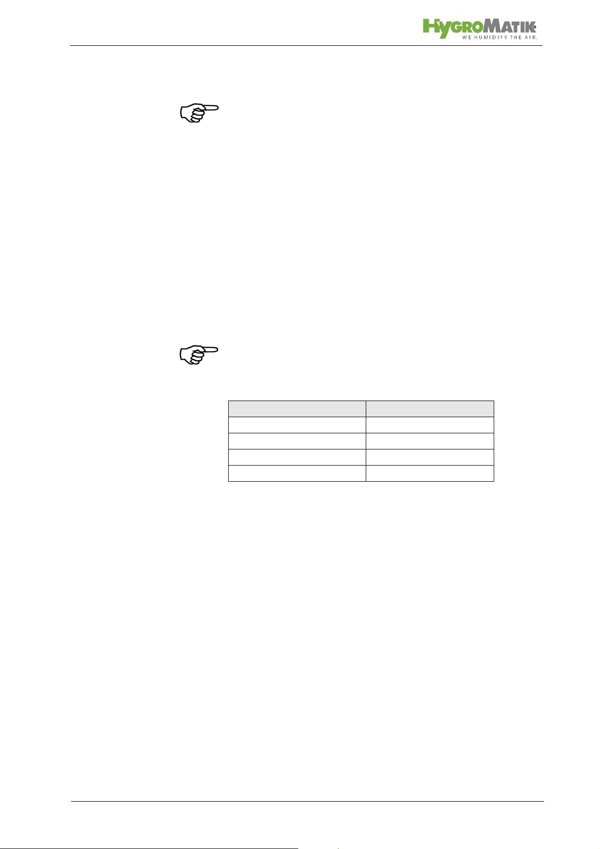
Time limits for filing freight claims with shipping companies are*:
Shipping Companies After Receipt of Goods
Mail no later than 24 hours
Rail no later than 7 days
Truck and Rail Carriers no later than 4 days
Parcel Service immediately
* Time limits for some services subject to change.
3.6 Included in the Delivery
The delivery includes:
Unit of the selected humidifier type including selected
control.
Water installation hose 0,6m, 3/4".
Mounting set with anchors and screws. For HyLine
types HY45 to HY116, extra mounting bar.
Operating Instructions for the unit and the control.
Ordered accessories (steam manifold, steam hose,
condensate hose, etc.).
Maintenance o-ring set for steam cylinder.
Page 11

4. Operation and Installation
4.1 Mode of Operation
The HygroMatik steam humidifier utilizes the conductivity normally present in tap water for steam production. Electrodes
inside an enclosed steam cylinder are immersed directly into the
tap water. They are connected to the alternating current.
The conductivity of the water generates an electric current
between the electrodes. In this way, the electric power supplied
is converted directly into heat without energy loss.
The amperage is a function of the available voltage, the
immersed electrode surface area, the average distance between
the electrodes and the water conductivity. The steam output of
the humidifier is determined by electric power usage, which is
regulated by increasing or decreasing the immersed surface
area of the electrodes.
Concurrently, a self-regulating control keeps conductivity within
a specified range.
The steam produced has a temperature of about 100°C with
minimal excess pressure ("pressureless steam"). It is largely
free of minerals and germ-free. Mineral deposits typically remain
behind in the cylinder.
4.2 Installation and Operation
By pressing the control switch („Pos. I”) the humidifier is turned
on. When the controller specifies an increase in humidity, the
main contactor is switched on and the electrodes (48) are supplied with power. The water inlet solenoid valve (25) feeds water
into the steam cylinder (16+19).
As soon as the electrodes are immersed, the current begins to
flow. The water is now heated. When the pre-selected output is
reached, the control turns off the solenoid valve and interrupts
the water supply.
After a short heating up period, the water between the electrodes begins to boil and vaporize. The vaporization lowers the
water level in the steam cylinder, reducing the output provided.
The inlet solenoid valve, equipped with a fine mesh filter, intermittently admits fresh water.
Humidifier power usage is continuously monitored. With a cold
start-up, the nominal current increases to 125% in order to
achieve quick-start output parameters. This activates the electronic overflow limiter which causes a partial draining of the cylinder . This reduces the immersed surface area of the electrodes,
lowering power usage.
Page 12
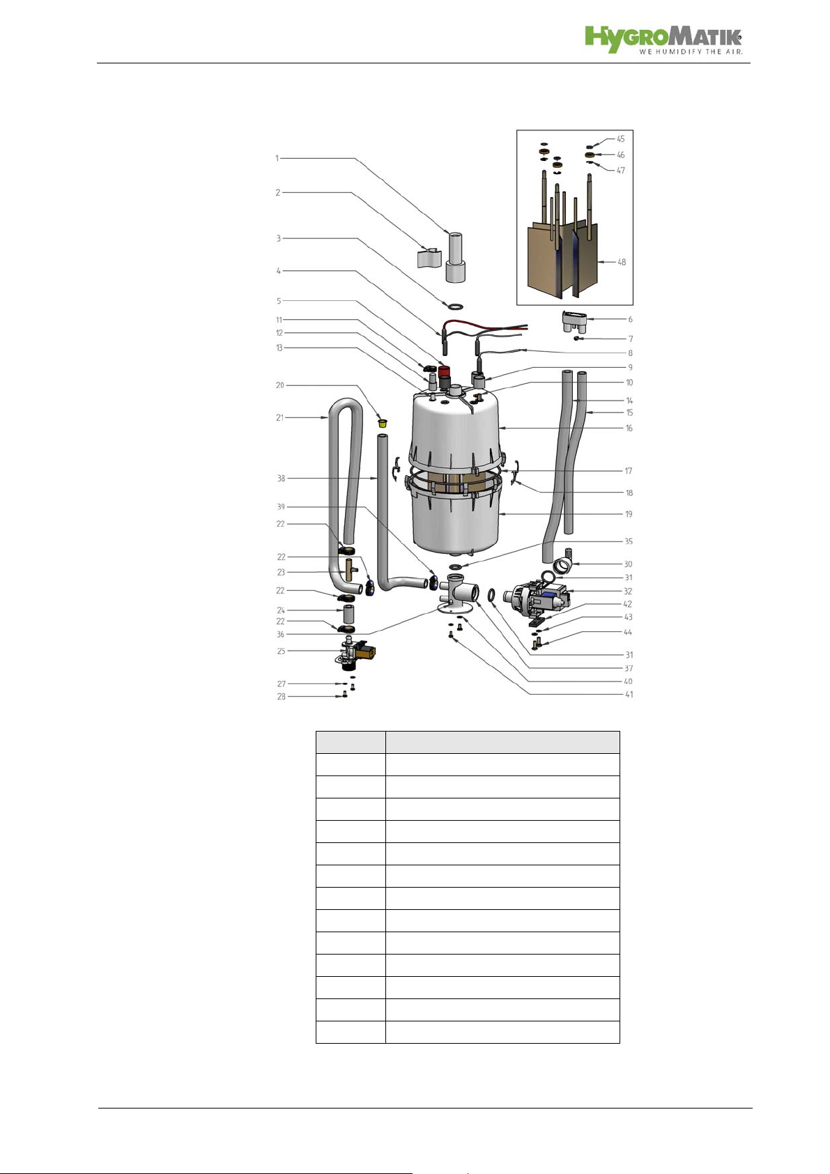
Please also see Section „Exploded View“.
Location Designation
1 adapter
6 vent pipe
10 max. water level sensor electrode
14 water drain, discharge
16 top part of steam cylinder
17 o-ring cylinder flange
18 cylinder flange and o-ring
19 lower part of cylinder
25 solenoid valve water inlet
32 blow-down pump
35 o-ring
37 cylinder base
48 electrodes
Page 13

The concentration of dissolved salts increases over time, which
can lead to a rise in the conductivity of the water. If this continues, conductivity may increase until a short circuit occurs. This
could damage the unit, but in any case would significantly
reduce the life span of the electrodes.
For this reason, regular, periodic blow-downs of some of the
concentrated water are very important. Following this procedure
as recommended provides stable cylinder water conductivity as
well as minimal water loss for the expected service life of the cylinder.
Water blow-down is performed by a blow-down pump (32). The
functioning of the blow-down pump is continuously monitored
during operation. If the pump is damaged, the steam humidifier
shuts down.
With normal water quality, the blow-down loss rate is between
7% and 15% of the amount of steam produced. The steam cylinder requires complete drainage every 3-8 days, regardless of
the water quality.
Mineral deposits settle in the open area below the electrodes
and are removed through periodic maintenance. The blow-down
pump itself has wide openings and can flush out smaller pieces
of mineral deposit. This extends the service life of the unit and
reduces the required maintenance interval.
During blow-downs, water flows from the pump into the drainage
system.
A sensor electrode (10) monitors the maximum
water capacity
of the cylinder. When the water level reaches the sensor electrode, the water supply is interrupted. This can occur when the
water has low conductivity or when the electrodes are worn out.
In the case of low water conductivity, however, this state usually
lasts only a short time. The built-in control and the large area
electrodes combine to produce a rapid rise in conductivity by
increasing the concentration of the water.
The steam cylinder consists of a top (16) and lower (19) part
joined with a cylinder flange. The seal between the cylinder and
cylinder base (37), as well as between the top and lower part of
the cylinder, is maintained using an o-ring (35+17).
For maintenance the cylinder can be drained by pressing the
control switch „Pos.II”.
Page 14
5. Installation
Warning: Installation of this unit to be attempted only by quali-
fied personnel. We accept no liability for damage due to faulty
installation.
Obey all safety notes and warnings present on the unit.
During installation the unit must be disconnected from its power
supply.
Attaching or installing additional components is permitted only
with the written consent of the manufacturer, or else the warranty is void.
Warning: If the installation of this unit is attempted by only one
person there is a risk that the unit drops down. We propose to
carry out the installation by two persons.
5.1 Steam Humidifier Operating Environment
Note: When selecting the installation site for the steam humidi-
fier, note that:
Ambient temperature must be between +5° and +40° C.
Relative humidity must not exceed 80% RH.
An Installation in a closed room requires aeration and if
neccessary temperature conditioning in order to reach
the above mentioned environmental conditions.
The minimum clearances indicated in the diagram
below must be observed; these are necessary to
ensure adequate ventilation for the housing.
HygroMatik humidifiers are not suitable for direct out-
door installation.
The steam humidifier should be installed as close as
possible to the steam manifold. Optimal performance is
guaranteed only with short lengths of steam and condensate hose
.
Hoses must be laid at a consistent 5-10% incline to pre-
vent sagging and kinking
.
The rear panel of the steam humidifier heats up during
operation (to a maximum of 60°C).
Take care that the
construction on which the unit is mounted is not made
of temperature-sensitive material.
Place the steam humidifier so that the unit is easily
accessible with sufficient space to perform maintenance.
The steam humidifier is not qualified for exterior appli-
cations.
Page 15
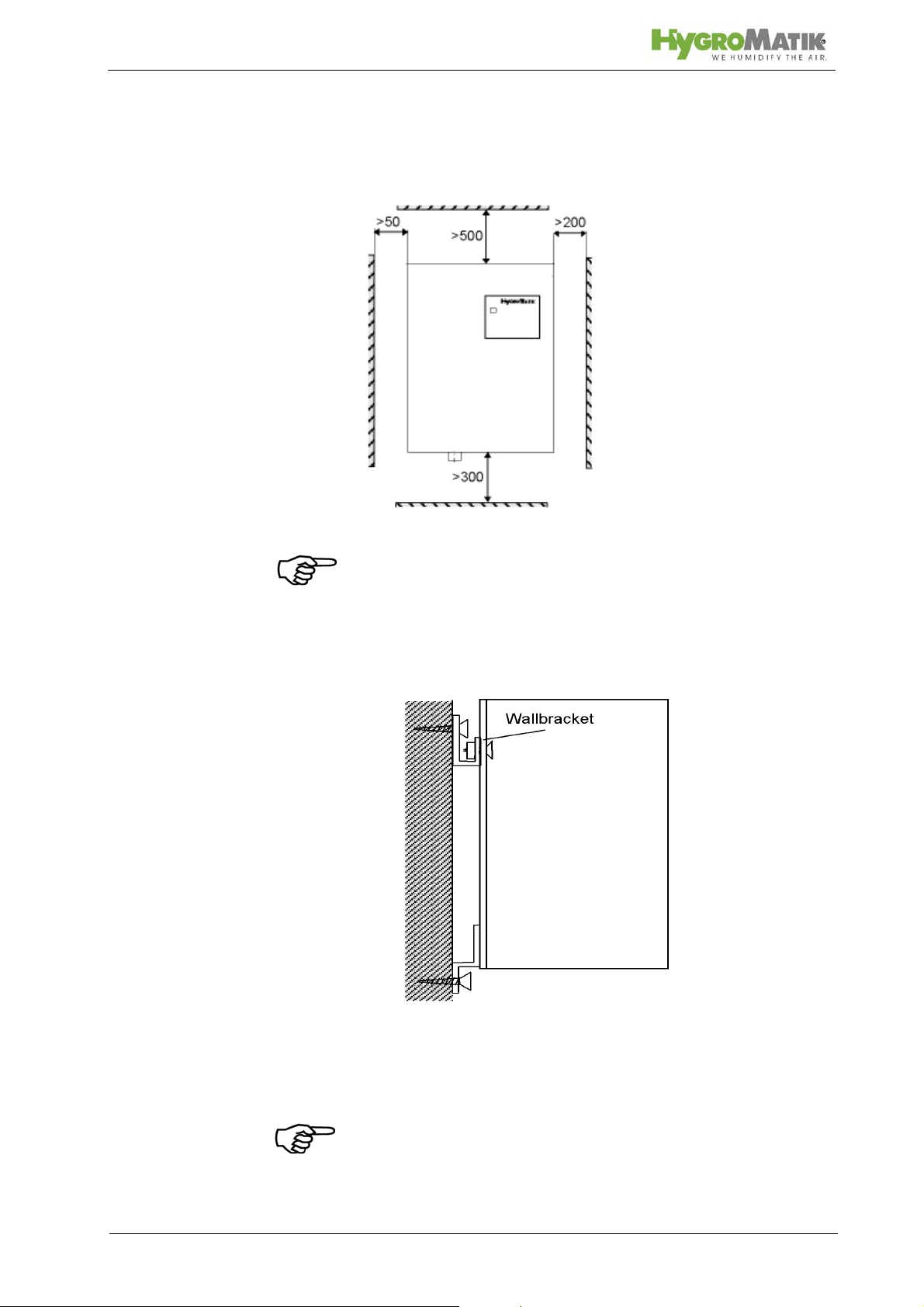
5.1.1 Fitting measures
Clearances
Note: When choosing the site for the steam humidifier, consider
the location of existing water installations (feed and drain lines).
Mounting Fixtures (for HY45 to HY116)
The unit should be mounted on a stable wall.
Note: To achieve a uniform immersed surface area for the electrodes, the humidifier must be installed plumb and level.
Page 16

to Install Units Type HY05- HY30:
» Place the steam humidifier in its intended location, use
a level to adjust position, and secure. See chapter "Unit
Dimensions".
» Attach the unit to the lower mounting fixtures.
to Install Units HY45- HY116:
» Fix bracket at the intended location. See chapter "Unit
Dimensions".
» Mount the unit, adjust position using a level, and screw
tightly into the mounting fixtures.
» Attach the unit to the lower mounting fixtures.
If no suitable wall is present, we recommend construction of a
free-standing console anchored to the floor.
Page 17

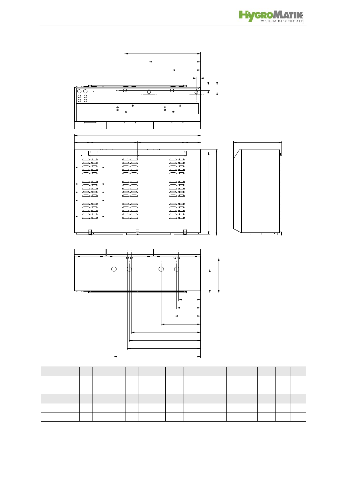
View from below
Rear view
5.1.2 Unit Dimensions HY05-HY45
View from top
Dimensions
HY05-HY08 481 449 216 415 438 43 35 35 120 120 103 - 147 65 HY13-HY23 654 520 284 486 619 63 35 38 210 152 136 - 184 96 -
Specifications in (mm)
Type /
HY30 710 560 327 515 665 58 50 38 250 172 156 - 197 106 HY45 788 653 405 588 742 68 50 48 300 209 200 330 227 153 283
a b c d e f g h i j k1 k2 m n1 n2
Page 18
c
g1
i1
g2
i2
h
f
d4 d2 d1 d3
b
j
m
n1
k1
n2
k2
n3
k3
n4
k4
e
a
5.1.3 Unit Dimensions HY60-HY116
Type / Dims. a b c d1 d2 d3 d4 e f g1 g2 h i1 i2 j
HY60 712 927 336 327 371 95 133 680 67 46 368 50 195 525 186
HY90-HY116 792 1061 404 398 398 132 132 758 67 35 432 50 238 635 220
Type / Dims k1 k2 k3 k4 m n1 n2 n3 n4
HY60 157 488 - - 204 110 441 - HY90-HY116 199 329 597 727 324 183 216 580 613
Specifications in (mm); * HY60 only one steam outlet
Page 19
Steam
Front View Wall Installation
Side View Wall Installation
5.2 Fan Unit (optional)
Note:
The fan unit should be positioned to avoid drafts. In gen-
eral, a minimum height of 2 m is sufficient.
Install the fan unit directly on a wall.
Fan Unit Type
for wall installation VG 08, 17, 30
Warning:
During operation and a soon afterwards the steam
nozzle is hot! If touched this can cause burns to the
skin.
During operation the cross-flow fan rotates. Do not
touch the fan during operation.
During operation hot steam discharges from the nozzle.
In the field of the visible steam cloud contact can cause
burns to the skin.
During operation the cross-flow fan rotates. Do not
touch the fan during operation.
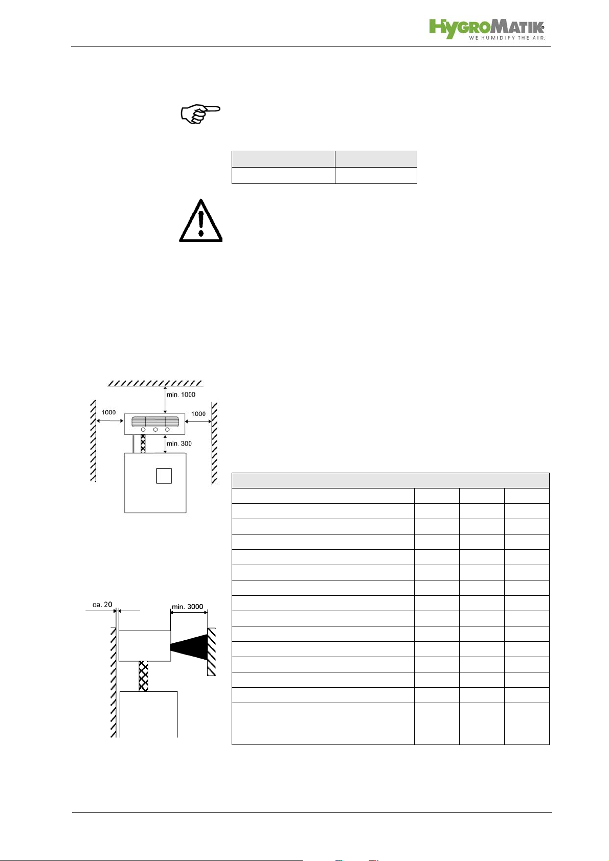
5.2.1 Fan Unit Type VG
Install the fan unit over the steam humidifier.
When employing multiple fan units, do not exceed a
maximum distance of 5 m from the steam humidifier.
Observe the clearances specified in the diagram below:
Technical Specifications Fan Unit VG
Fan Unit VG08 VG17 VG30
Quantity of Steam [kg/h] 8 17 30
Steam Inlet [mm]25 25 40
Condensate Outlet [mm]12 12 12
Airflow Capacity [cbm/h] 185 185 350
Nominal Output [W] 35 35 67
Nominal voltage [V] 230 230 230
Dimensions W [mm] 441 507 550
H [mm] 171 171 171
D [mm] 180 237 277
Weight [kg] 4,5 6 7
Sound Level (1m dis-
[dB(A)] 50 57 59
tance to the source of
noise)
Page 20
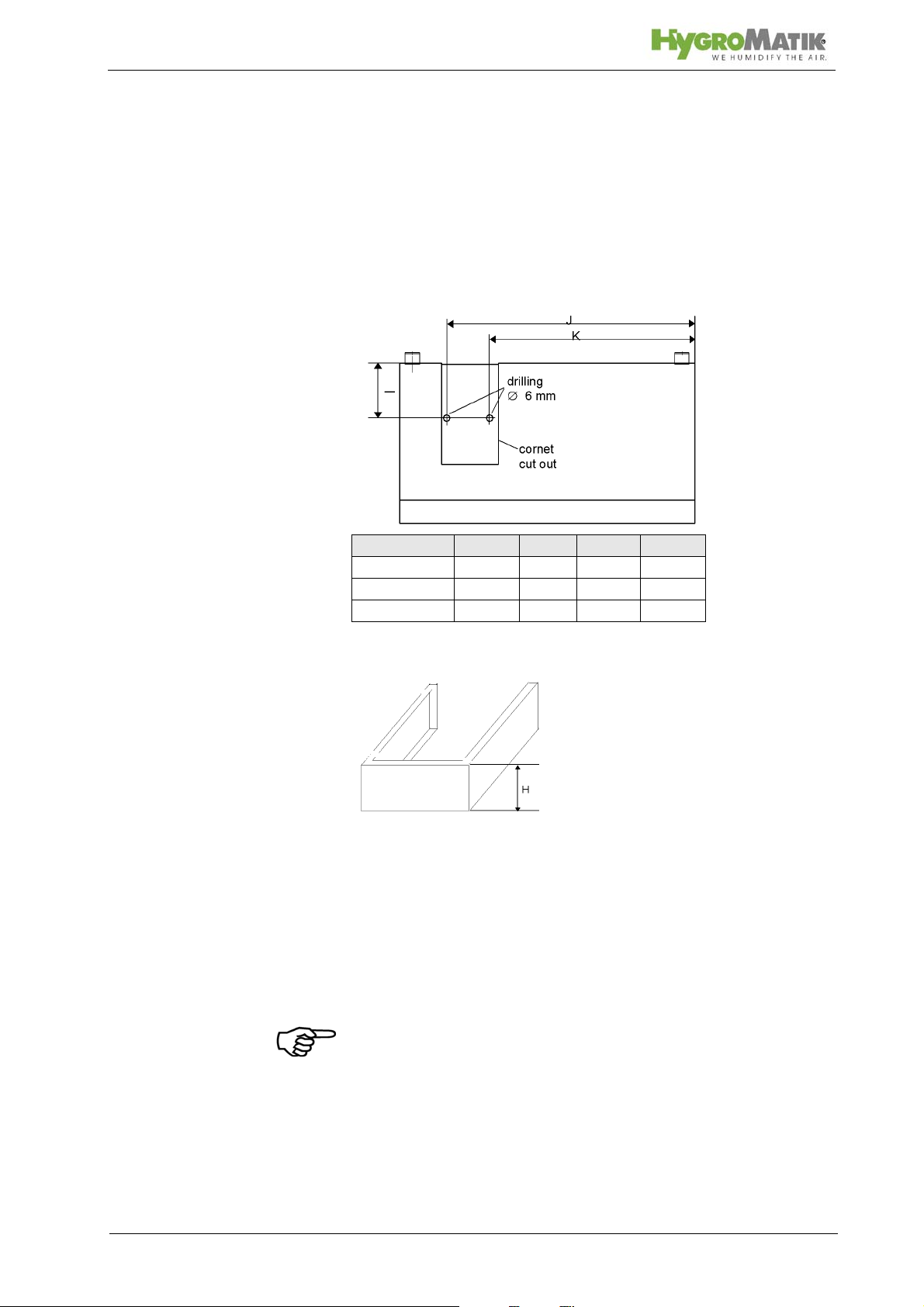
5.2.2 Fan Unit Cover
Covers (optional) for T ypes HY05 and HY30 are available to protect the steam and condensate hoses between the steam
humidifier and the fan unit. The vertical distance between the
humidifier and the fan unit is determined by the height of the
cover (see Table of Dimensions H).
» Drill two holes in the housing as specified in the fol-
lowing diagram.
Type H [mm] I [mm] J [mm] K [mm]
HY05- HY08 175 80 373 266,5
HY13-HY23 280 105 422 310
HY30 280 105 452 340
» Install the steam humidifier and fan unit on the wall (dis-
tance H). Diameter ofbore 6 mm Panel cutout
» Secure the steam hose between the humidifier and fan
unit with hose clamps
» Also using a hose clamp, attach the condensate hose
to the fan unit.
» Run condensate hose along the rear of the unit to the
water discharge. (Also see chapter "Water Discharge".)
» Lay the loop of condensate hose 200 mm directly
above the drain. The loop acts as a vapor barrier.
Note: Condensate cannot be fed directly back into the steam
cylinder.
» Slide cover between humidifier and fan unit.
» Fasten cover with the two screws supplied. Screw from
the steam panel outwards.
Page 21
 Loading...