

HygroMatik HY13, HY05, HY23, HY30, HY60 Series Manual
...
Electrode Steam HumidifierElectrode Steam Humidifier
ÁHYL.CSA9È
HYL.CSA
E-8881700
IMPORTANT: READ AND SAVE
THESE INSTRUCTIONS
Manual

Certain computer programs contained in this product [or device] were developed by HygroMatik
GmbH ("the Work(s)").
© Copyright HygroMatik GmbH
HyLine CSA [16.02.2017]
Current version of this manual can be found at: www.hygromatik.de/us
All rights reserved.
HygroMatik GmbH grants the legal user of this product [or device] the right to use the Work(s)
solely within the scope of the legitimate operation of the product [or device]. No other right is
granted under this licence. In particular and without prejudice to the generality of the foregoing,
the Work(s) may not be used, sold, licensed, transferred, copied or reproduced in whole or in
part or in any manner or form other than as expressly granted here without the prior written consent of HygroMatik GmbH.
Information in this manual is subject to change or alteration without prior notice.
Risk of electrical shock!
Hazardous electrical high voltage!
All electrical work to be performed by certified expert staff (electricians or expert personnel with
eqivalent training) only. Disconnect power supply prior to work start!
Page 2

1. Introduction ....................................................................................................................... 5
1.1 Typographic Distinctions ...................................................................................................5
1.2 Documentation .................................................................................................................. 5
1.3 Symbols in Use ................................................................................................................. 6
1.3.1 Specific Symbols related to Safety Instructions ............................................................. 6
1.3.2 General Symbols ............................................................................................................ 6
1.4 Intended Use ..................................................................................................................... 6
2. Safety Instructions ............................................................................................................ 8
2.1 Guidelines for Safe Operation ........................................................................................... 8
2.1.1 General ........................................................................................................................... 8
2.1.2 Unit control ..................................................................................................................... 8
2.1.3 Unit operation ................................................................................................................. 8
2.1.4 Mounting, maintenance, repair and dismantling of the unit ............................................ 9
2.1.5 Electrical ......................................................................................................................... 9
3. Transport ............................................................................................................................ 10
3.1 Overview ........................................................................................................................... 10
3.2 Carton outer Size and Weight ........................................................................................... 10
3.3 Packing .............................................................................................................................. 11
3.4 Interim Storage .................................................................................................................. 11
3.5 Check for Complete and Correct Delivery of Goods ......................................................... 11
3.6 Included in the Delivery ..................................................................................................... 11
4. Functional description and device composition ............................................................ 12
4.1 Mode of Operation ............................................................................................................. 12
4.2 Structure and operation of the device ............................................................................... 12
5. Installation ......................................................................................................................... 13
5.1 Environment Parameters to be met and Mounting Recommendations ............................. 13
5.1.1 Fitting measures ............................................................................................................. 15
5.1.2 Unit Dimensions HY05-HY45 ......................................................................................... 17
5.1.3 Unit Dimensions HY60-HY116 ....................................................................................... 19
5.2 Fan Units (Options) ........................................................................................................... 21
5.2.1 Fan Unit Type VG ........................................................................................................... 21
5.2.2 Fan Unit Cover ............................................................................................................... 22
5.3 Absorption Distance BN .................................................................................................... 23
5.3.1 Determining the Absorption Distance ............................................................................. 23
5.3.2 Absorption Distance Nomogram .................................................................................... 25
5.4 Steam Manifold ................................................................................................................. 26
5.4.1 Guidelines for Installation ............................................................................................... 26
5.4.2 Recommendations for dimensioning .............................................................................. 27
5.5 Steam line and condensate hose layout .......................................................................... 31
5.5.1 Guidelines for steam line design ................................................................................... 31
5.5.2 Condensate hose layout ................................................................................................. 32
5.5.3 Steam line and condensate hose installation types ....................................................... 32
Page 3

5.6 Unit Installation Check ....................................................................................................... 35
6. Water Installation .............................................................................................................. 36
6.1 Operation with Softened Water ......................................................................................... 37
6.2 Water Supply ..................................................................................................................... 38
6.3 Water discharge ................................................................................................................ 39
6.4 HyFlow Provision (Special order unit types) ...................................................................... 40
6.5 Water Installation Checklist ...............................................................................................41
7. Electrical Connection ........................................................................................................ 42
7.1 Electrical Installation .......................................................................................................... 42
7.2 Cable Connections ............................................................................................................ 44
7.3 Safety Interlock .................................................................................................................. 45
7.4 Wiring Diagram .................................................................................................................. 45
7.5 Electrical Installation Checklist ..........................................................................................45
8. Commissioning ................................................................................................................. 47
9. Maintenance ....................................................................................................................... 48
9.1 Maintenance Work ............................................................................................................ 49
9.2 Access to Electrical Enclosure .......................................................................................... 50
9.3 Removing and Cleaning the Steam Cylinder .................................................................... 50
9.4 Electrode wear .................................................................................................................. 57
9.4.1 Original Electrode Lengths ............................................................................................. 57
9.4.2 Uneven Electrode Lengths ............................................................................................. 58
9.5 Replacing Electrodes ........................................................................................................ 58
9.6 Cleaning the blow- down pump ......................................................................................... 60
9.7 Cleaning the Water Inlet Solenoid Valve ........................................................................... 60
9.8 Cleaning the Water Inlet Solenoid Valve and HyFlow System Separator (special models only)
61
9.9 Checking Cable Connections and Electrode Cables ......................................................... 62
9.10 Checking Hoses .............................................................................................................. 63
9.11 Checking Operation ......................................................................................................... 63
10. Dismantling ...................................................................................................................... 64
11. CSA Certificate of Compliance ...................................................................................... 65
12. Spare Parts ...................................................................................................................... 68
13. Fax Form - Order for spare parts ................................................................................... 77
14. Exploded View ................................................................................................................. 79
15. View of housing ............................................................................................................... 80
16. Technical Specification .................................................................................................. 81
Page 4

1. Introduction
Dear Customer,
Thank you for choosing a HygroMatik steam humidifier.
HygroMatik steam humidifiers represent the latest in humidification technology.
In order to operate your HygroMatik steam humidifier safely, properly and efficiently, please read these operating instructions.
Employ your steam humidifier only in sound condition and as
directed. Consider potential hazards and safety issues and follow all the recommendations in these instructions.
If you have additional questions, please contact us:
Tel.: +49-(0)4193 / 895-0 (Main Number)
Tel.: +49-(0)4193 / 895-293 (Technical Support Hotline)
Fax: +49-(0)4193 / 895-33
e-mail: hotline@HygroMatik.de
For all technical questions or spare parts orders, please be prepared to provide unit type and serial number (see name plate on
the unit).
1.1 Typographic Distinctions
• preceded by a bullet: general specifications
» preceded by an arrow: Procedures for servicing or
maintenance which should or must be performed in the
indicated order
Installation step which must be checked off
italics Terms used with graphics or drawings
1.2 Documentation
Retention
Please retain these operating instructions in a secure, always
accessible location. If the product is resold, turn the documentation over to the new operator. If the documentation is lost, please
contact HygroMatik.
Versions in Other Languages
These operating instructions are available in several languages.
If interested, please contact your expert dealer.
Page 5
Please note
1.3 Symbols in Use
1.3.1 Specific Symbols related to Safety Instructions
According to ANSI Z535.6 the following signal words are used
within this document:
DANGER indicates a hazardous situation which, if not avoided,
will result in death or serious injury.
WARNING indicates a hazardous situation which, if not avoided,
could result in death or serious injury.
CAUTION indicates a hazardous situation which, if not avoided,
could result in minor or moderate injury.
NOTICE is used to address practices not related to physical
injury.
1.3.2 General Symbols
This symbol is used whenever a situation requires special attention beyond the scope of safety instructions.
1.4 Intended Use
The HygroMatik steamgenerator serves for steam production
based on various water qualities or partially softened water
(valid for all of the HygroMatik humidifier models). With the HeaterLine, HeaterCompact/Kit and HeaterSlim familiy of products,
also fully desalinated water/cleaned condensate may be used.
Only use supply water featuring a conductivity of 125 to
1250 µS/cm.
Page 6
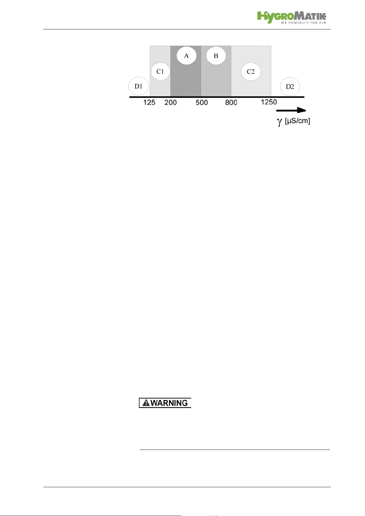
D1: Lower threshold
C1: Range of reduced conductivity (adjustments recommended)
A: Normal tap water
B: Range of heightened conductivity
C2: Range of high conductivity (adjustments recommended)
D2: Upper threshold
Proper usage also comprises the adherence to the conditions
specified by HygroMatik for:
• installation
• dismantling
• reassembly
• commissioning
• operation
• maintenance
• disposal.
Only qualified and authorised personnel may operate the unit.
Persons transporting or working on the unit must have read and
understood the corresponding parts of the Operation and Maintenance Instructions and especially the chapter 2. „Safety
Notes“. Additionally, operating personnel must be informed of
any possible dangers. You should place a copy of the Operation
and Maintenance Instructions at the unit‘s operational location
(or near the unit).
By construction, HygroMatik steam humidifiers are not qualified for exterior application.
Risk of scalding!
Steam with a temperature of up to 212 °F is produced.
Do not inhalate steam directly in order to avoid respiratory
damage!
Page 7
2. Safety Instructions
These safety instructions are required by law. They promote
workplace safety and accident prevention.
2.1 Guidelines for Safe Operation
2.1.1 General
Comply with the accident prevention regulation „DGUV Regulation 3“ to prevent injury to yourself and others. Beyond that,
national regulations apply without restrictions.
2.1.2 Unit control
Do not perform any work which compromises the safety of the
unit. Obey all safety notes and warnings present on the unit.
In case of a malfunction or electrical power supply disruption,
switch off the unit immediately and prevent from restart. Repair
malfunctions promptly.
Restricted use
This unit is not designed for the use by persons (also children)
with limited physical, sensory and mental abilities - or without
knowledge and experience - unless they are supervised or trained by a person, who is responsible for their safety.
Supervise children in order to ensure that they will not play with
the unit.
2.1.3 Unit operation
Risk of scalding!
In case of leaking or defective components, hot steam may exit
in an uncontrolled manner.
Switch off unit immediately.
Risk of material damage!
The unit may be damaged if switched on repeatedly following a
malfunction without prior repair.
Rectify defects in return!
• The unit must not be operated on a DC power supply
• The unit may only be used connected to a steam pipe that
safely transports the steam (not valid device type MiniSteam)
Page 8

• Regularly check that all safety and monitoring devices are
functioning normally
• Do not remove or disable safety devices
2.1.4 Mounting, maintenance, repair and dismantling
of the unit
The HygroMatik steam humidifier is IP20 protected. Make sure
that the unit is not object to dripping water in the mounting location.
When installation is made in a room without a drain, safety precautions must be taken in order for to shut off the humidifier‘s
water supply in event of a leak.
• Use genuine spare parts only
• After any repair work, have qualified personnel check the
safe operation of the unit
• Attaching or installing of additional components is per-
mitted only with the written consent of the manufacturer
• The operator is responsible for the disposal of unit components as required by law
2.1.5 Electrical
Risk of electrical shock!
Hazardous electrical high voltage!
Any work on the electrical system must only be performed by
qualified personnel.
Disconnect unit components from electrical power supply prior
to work.
After electrical installation or repair work, test all safety mechanisms (such as grounding resistance).
Only use original fuses with the appropriate amperage rating.
Regularly check the unit‘s electrical equipment. Promptly repair
any damage such as loose connections or burned wiring.
Responsibility for intrinsically safe installation of the HygroMatik
steam humififiers (steam generators) is incumbent on the installing specialist company.
Page 9
Please note
3. Transport
3.1 Overview
Proceed carefully when transporting the steam humidifier in
order to prevent damage due to stress or careless loading and
unloading.
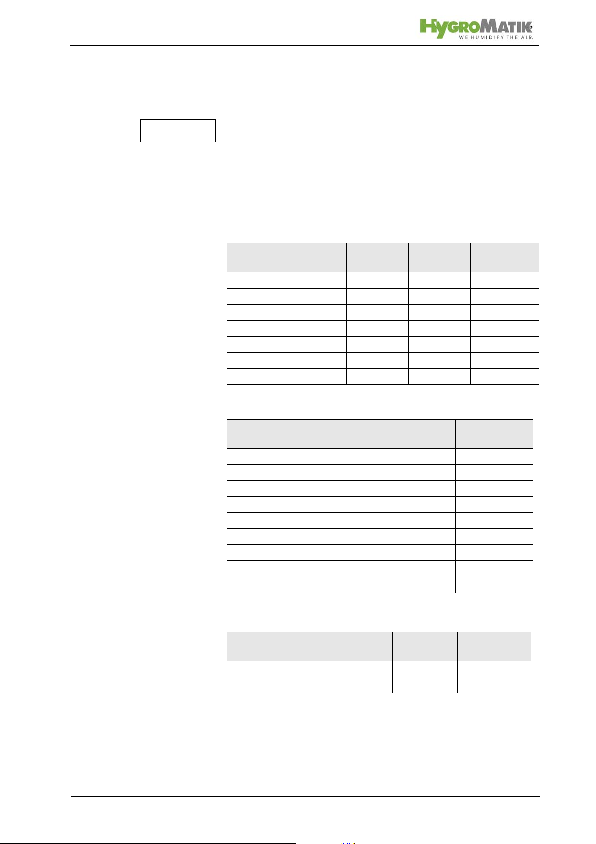
3.2 Carton outer Size and Weight
HyLine:
Type* Height
[cm]/[inch]
HY05- 08 58/22.8 56/22.0 32/12.6 16/35.3
HY13- 17 75/29.5 63/24.8 37/15.6 24/52.9
HY23 75/29.5 63/24.8 37/15.6 25/55.1
HY30 81/31.9 67/26.4 41/16.1 33/72.8
HY45 88/34.6 76/29.9 48/18.9 46/101.4
HY60 80/31.5 104/40.9 41/16.1 54/119.0
HY90- 116 90/35.4 117/46.1 48/18.9 77/169.8
CompactLine:
Type* Height
[cm]/[inch]
C01 46/18.1 45/17.7 26/10.2 11/24.3
C02 48/18.9 44/17.3 31/12.2 12/26.5
C06 52/20.4 50/19.7 28/11.0 13/28.7
C10 58/22.8 51/20.1 31/12.2 14/30.9
C17 75/29.5 54/21.3 37/14.6 22/48.5
C22 75/29.5 54/21.3 37/14.6 22/48.5
C30 75/29.5 58/22.8 37/14.6 23/50.7
C45 81/33.1 63/24.8 41/16.1 25/55.1
C58 90/35.4 72/28.3 48/18.2 36/79.4
Width [cm]/
Width
[cm]/[inch]
[inch]
Depth
[cm]/[inch]
Depth [cm/
[inch]]
Weight
[kg]/[lbs]
Weight [kg]
MiniSteam:
Type**Height
[cm]/[inch]
MS 5 59/23.2 48/18.9 28/11.0 13/28.7
MS 10 68/26.8 51/20.1 31/12.2 15/33.1
* Dimensions and weights may vary slightly.
Page 10
Width [cm]/
[inch]
Depth [cm]/
[inch]
Weight[kg]
Please note
Please note
3.3 Packing
Notice the symbols affixed to the packing box.
3.4 Interim Storage
Store the unit in a dry place and protect against frost.
3.5 Check for Complete and Correct Delivery of
Goods
Upon receipt of the unit, confirm that:
• the type and serial number on the name plate match
those specified in the order and delivery documents
and
• the equipment is complete and all parts are in perfect
condition
In case of damage during shipment or missing parts, immediately notify the carrier or supplier in writing.
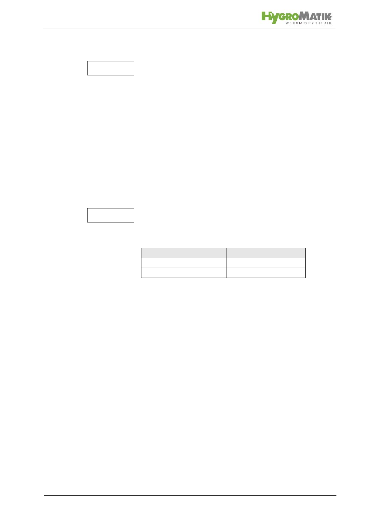
Time limits for filing freight claims with shipping companies are*:
Shipping Companies After Receipt of Goods
Carriers no later than 4 days
Parcel Service immediately
* Time limits for some services subject to change.
3.6 Included in the Delivery
The delivery includes:
• Unit of the selected humidifier type including selected
control.
• Water installation hose 0,6m/23.6inch, 3/4".
• Mounting set with anchors and screws. For HyLine
types HY45 to HY116, extra mounting bar.
• Operating Instructions for the unit and the control.
• Ordered accessories (steam manifold, steam hose,
condensate hose, etc.).
• Maintenance o-ring set for steam cylinder.
Page 11

4. Functional description and device compo-
sition
4.1 Mode of Operation
Electrodes through which electrical current flows heat conductive water in a cylinder to create unpressurized, hygienic steam.
Electrode steam humidifiers are suitable for use with normal tap
water, as this is normally conductive.
The steam produced has a temperature of about 100°C/212°F
with minimal excess pressure ("pressureless steam"). It is
largely free of minerals and germ-free.
4.2 Structure and operation of the device
By pressing the control switch („Pos. I”) the humidifier is turned
on. When the controller specifies an increase in humidity, the
main contactor is switched on and the electrodes ((48) number
in paranthesis refers to exploded view fig.) are supplied with
power. The water inlet solenoid valve (25) feeds water into the
steam cylinder (16+19).
As soon as the electrodes are immersed, the current begins to
flow. The water is now heated. When the pre-selected output is
reached, the control turns off the solenoid valve and interrupts
the water supply.
After a short heating up period, the water between the electrodes begins to boil and vaporize. The vaporization lowers the
water level in the steam cylinder, reducing the output provided.
The inlet solenoid valve, equipped with a fine mesh filter, intermittently admits fresh water.
Humidifier power usage is continuously monitored. With a cold
start-up, the nominal current increases to 125% in order to
achieve quick-start output parameters.
The concentration of dissolved salts increases over time, which
can lead to a rise in the conductivity of the water. For this reason, regular, periodic blow-downs of some of the concentrated
water are very important.
Water blow-down is performed by a blow-down pump (32).
With normal water quality, the blow-down loss rate is between
7% and 15% of the amount of steam produced. The steam cylinder requires complete drainage every 3-8 days, regardless of
the water quality.
During blow-downs, water flows from the pump into the drainage
system.
A sensor electrode (10) monitors the maximum
of the cylinder. When the water level reaches the sensor elec-
trode, the water supply is interrupted.
Page 12
water capacity
Please note
Please note
5. Installation
General risk of personal injury!
Personnel not familiar with professional installation methods
may sustain physical damage.
Installation of this unit to be accomplished only by qualified personnel (persons with completed training in the plumbing field
and in the field of electrical installation work, respectively)!
Risk of electrical shock!
Hazardous electrical high voltage!
Unit must be disconnected from electrical power supply during
installation.
Risk of foot injuries!
Unit may drop during mounting involving a single person.
Helping hand of a second person is required.
HygroMatik accepts no liability for damage due to faulty installation.
Attaching or installing additional components is permitted only
with the written consent of the manufacturer, or else the warranty is void.
5.1 Environment Parameters to be met and
Mounting Recommendations
When selecting the installation site for the steam humidifier, take
the following into account:
• The minimum clearances indicated in the fitting measures
section must be observed in order to ensure adequate unit
ventilation and allow for unobstructed access in case of
maintenance
• Protection class IP20
• By design, HygroMatik steam humidifiers are not qualified
for outdoor installation (electronical components and
water-bearing parts may be damaged)
Page 13

• Ambient temperature must lie between +41 and +104 °F in
order to protect the unit electronics against damage; frost
may damage the steam cylinder
• Relative humidity must not exceed 80 % r.h., since values
beyond may lead to electronic malfunction or damage
• Installation in a closed room requires aeration and, eventually, temperature conditioning in order to meet the a.m.
environmental conditions
• The steam humidifier should be installed as close as possible to the steam manifold. Optimum performance is only
guaranteed when steam and condensate hoses are kept
short
• Make use of existing water connections for supply and
draining
• Hoses must be laid at a consistent 5 to 10 % incline/
decline in order to definitely prevent sagging and kinking
• Mount the unit on a stable, preferably solid wall offering
the bearing capacity required (s. unit technical specifications). If such a wall is not at hand, the unit may be attached
to a stand bracket firmly bolted to the floor
• Mounting the unit must be perpendicularly aligned in both
the vertical and horizontal axis (plumb and level) in order
to achieve uniform immersed surface areas for the electrodes
• The steam humidifier rear panel heats up during operation
(to a maximum of 158 °F). Take care that the construction
on which the unit is to be mounted is not made of temperature-sensitive material
Page 14
> 300mm/
> 500mm/
> 200mm/
> 50mm/
Please note
Please note
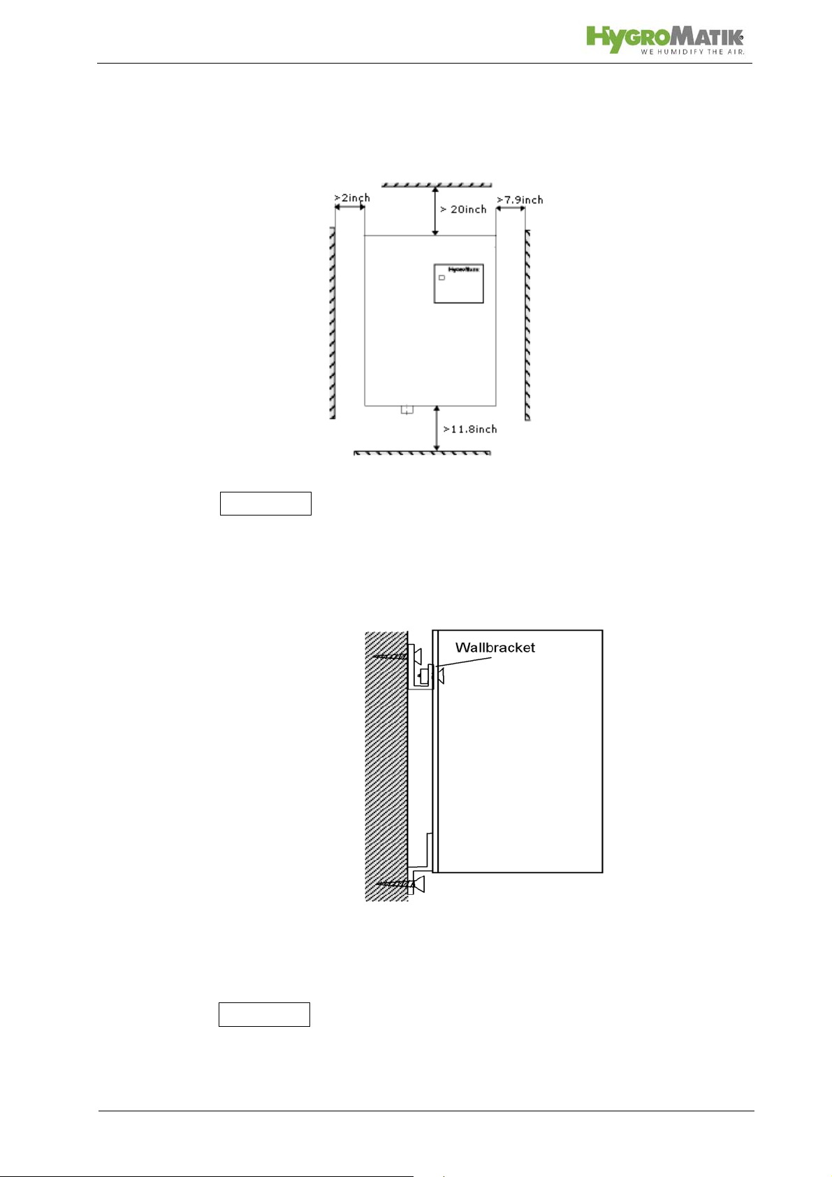
5.1.1 Fitting measures
Clearances
When choosing the site for the steam humidifier, consider the
location of existing water installations (feed and drain lines).
Mounting Fixtures (for HY45 to HY116)
The unit should be mounted on a stable wall.
To achieve a uniform immersed surface area for the electrodes,
the humidifier must be installed plumb and level.
Page 15

to Install Units Type HY05- HY30:
» Place the steam humidifier in its intended location, use
a level to adjust position, and secure. See chapter "Unit
Dimensions".
» Attach the unit to the lower mounting fixtures.
to Install Units HY45- HY116:
» Fix bracket at the intended location. See chapter "Unit
Dimensions".
» Mount the unit, adjust position using a level, and screw
tightly into the mounting fixtures.
» Attach the unit to the lower mounting fixtures.
If no suitable wall is present, we recommend construction of a
free-standing console anchored to the floor.
Page 16
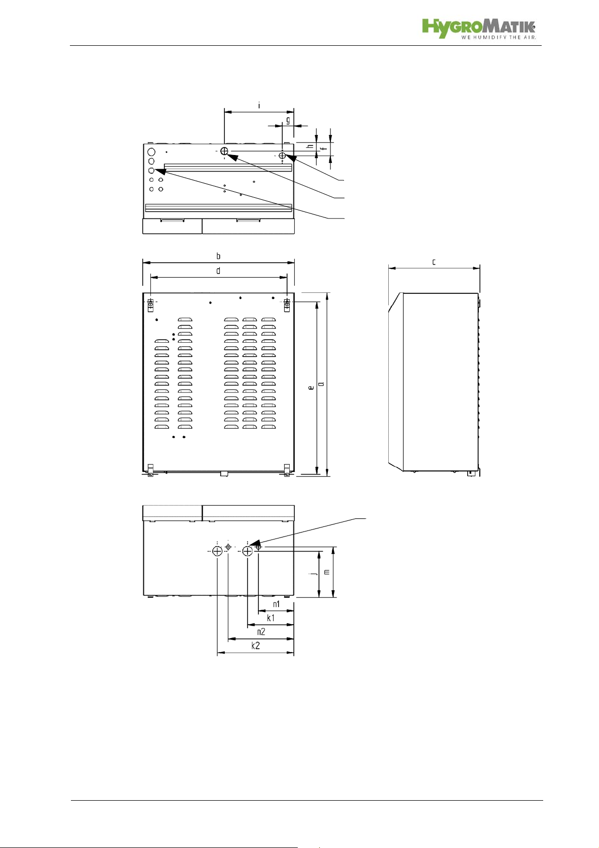
Water inlet
Waste water connection
Cable entries
Steam outlet (1x/2x)
View from below
Rear view
5.1.2 Unit Dimensions HY05-HY45
View from top
Page 17

Type /
Dimensions
a b c d e f g h i j k1 k2 m n1 n2
[mm]/
[inch]
HY05-HY08 480/
HY13-HY23 650/
HY30 708/
HY45 788/
18.9
25.6
27.9
31.0
449/
17.7
522/
20.6
561/
22.1
654/
25.7
251/
9.9
301/
11. 9
344/
13.5
405/
16.0
415/
16.3
486/
19.1
515/
22.3
588/
23.2
438/
17.2
619/
24.4
665/
26.2
742/
29.2
43/
1.7
63/
2.5
58/
2.3
68/
2.7
35/
1.4
35/
1.4
50/
2.0
50/
2.0
35/
1.4
38/
1.5
38/
1.5
48/
1.9
120/
4.7
210/
8.3
250/
9.8
300/
11.8
120/
4.7
152/
6.0
172/
6.8
209/
8.2
103/
4.1
136/
5.4
156/
6.1
200/
7.9
- 147/
- 184/
- 197/
330/
13.0
5.8
7.2
7.8
227/
9.0
65/
2.6
96/
3.8
106/
4.2
153/
6.0
-
-
-
283/
11. 1
Page 18
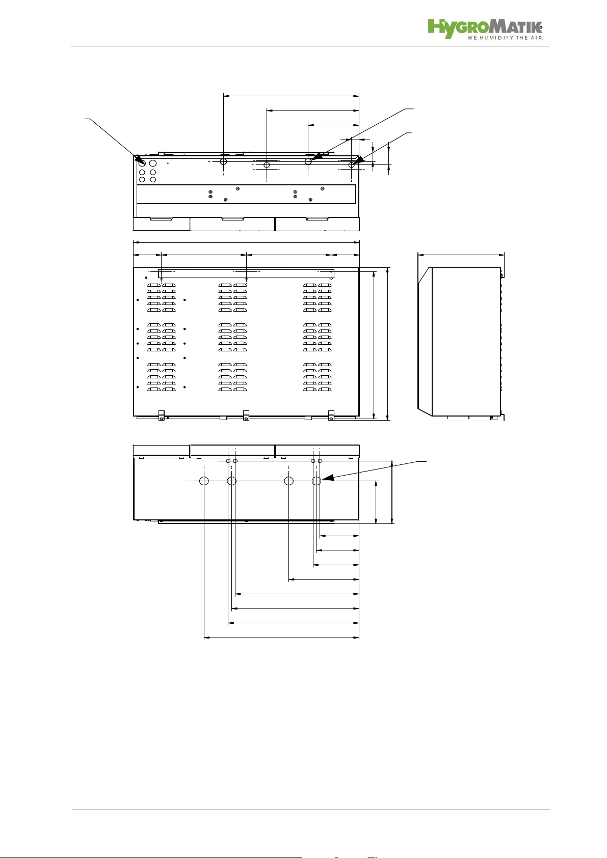
c
g1
i1
g2
i2
h
f
d4 d2 d1 d3
b
j
m
n1
k1
n2
k2
n3
k3
n4
k4
e
a
Water inlet (2x)
Waste water connection
(2x)
Cable entries
Steam outlet (2x/4x)
5.1.3 Unit Dimensions HY60-HY116
Page 19
Type / Dims.
[mm]/
a b c d1 d2 d3 d4 e f g1 g2 h i1 i2 j
[inch]
HY60 709/
HY90-HY116 788/
27.9
31.0
927/
36.5
1061
41.8
333/
13.1
403/
15.9
327/
12.9
398/
15.7
371/
14.6
398/
15.7
95/
3.7
132/
5.2
133/
5.2
132/
5.2
680/
26.8
758/
29.8
Type / Dims.
[mm]/
k1 k2 k3 k4 m n1 n2 n3 n4
[inch]
HY60 157/
HY90-HY116 199/
6.2
7.8
488/
19.2
329/
13.0
- - 204/
597/
727/
23.5
28.6
8.0
324/
12.8
110 /
4.3
183/
7.2
441/
17.4
216/
8.5
--
580/
22.8
* HY60 only one steam outlet per zylinder
67/
2.6
67/
2.6
613/
24.1
46/
1.8
35/
1.4
368/
14.5
432/
17.0
50/
2.0
50/
2.0
195/
7.7
238/
9.4
525/
20.7
635/
25.0
186/
7.3.
220/
8.7
Page 20

Please note
11.8/300 mm
minimum
39.4 in/
1000 mm
39.4 in/
1000 mm
Steam
approx. 0.8 in/20 mm
9.8 ft/3.0 m minimum
Front View Wall Installation
Side View Wall Installation
5.2 Fan Units (Options)
The fan units should be positioned in a way that avoids drafts. In
general, a minimum height of 6 ft 7 in (2 m) above floor is sufficient. Install the fan unit directly on a wall.
Risk of skin burning or scalding!
During operation and for at least 10 mins afterwards the steam
nozzles are hot. Do not touch!
During operation hot steam discharges from the nozzles.
Avoid any contact in the field of the visible steam cloud.
Due to improper installation or contamination hot water may drip
from the nozzles. Do not reside in the area directly under the
nozzels.
Rotating parts!
During operation the cross-flow fan rotates.
Do not touch!
Do not introduce any matter through the fan grid.
5.2.1 Fan Unit Type VG
• Install the fan unit above the steam humidifier
• When employing multiple fan units, do not exceed a
maximum distance of 5 m from the steam humidifier
• Observe the clearances specified in the figs.
Technical of specifications VG fan units
Fan Unit VG08 VG17 VG30
Quantity of Steam [lb/h /kg/h] 17.6/8 37.5/17 66/30
Steam Inlet [In/mmφ] 0.98/25 0.98/25 1.57/40
Condensate Outlet [in/mmφ] 0.55/14 0.47/12 0.47/12
Nominal Output [W] 26 35 67
Nominal voltage [V] 230 230 230
Dimensions W [in/mm] 17.4/441 20/507 21.7/550
H [in/mm] 6.7/171 6.7/171 6.7/171
D [in/mm] 7.1/180 9.3/237 11/277
Weight [lb/kg] 7.9/3.6 13.2/6 15.4/7
Sound Level (3 ft 3.37
in /1m distance to the
source of noise)
[dB(A)] 52 54 57
Page 21
Please note
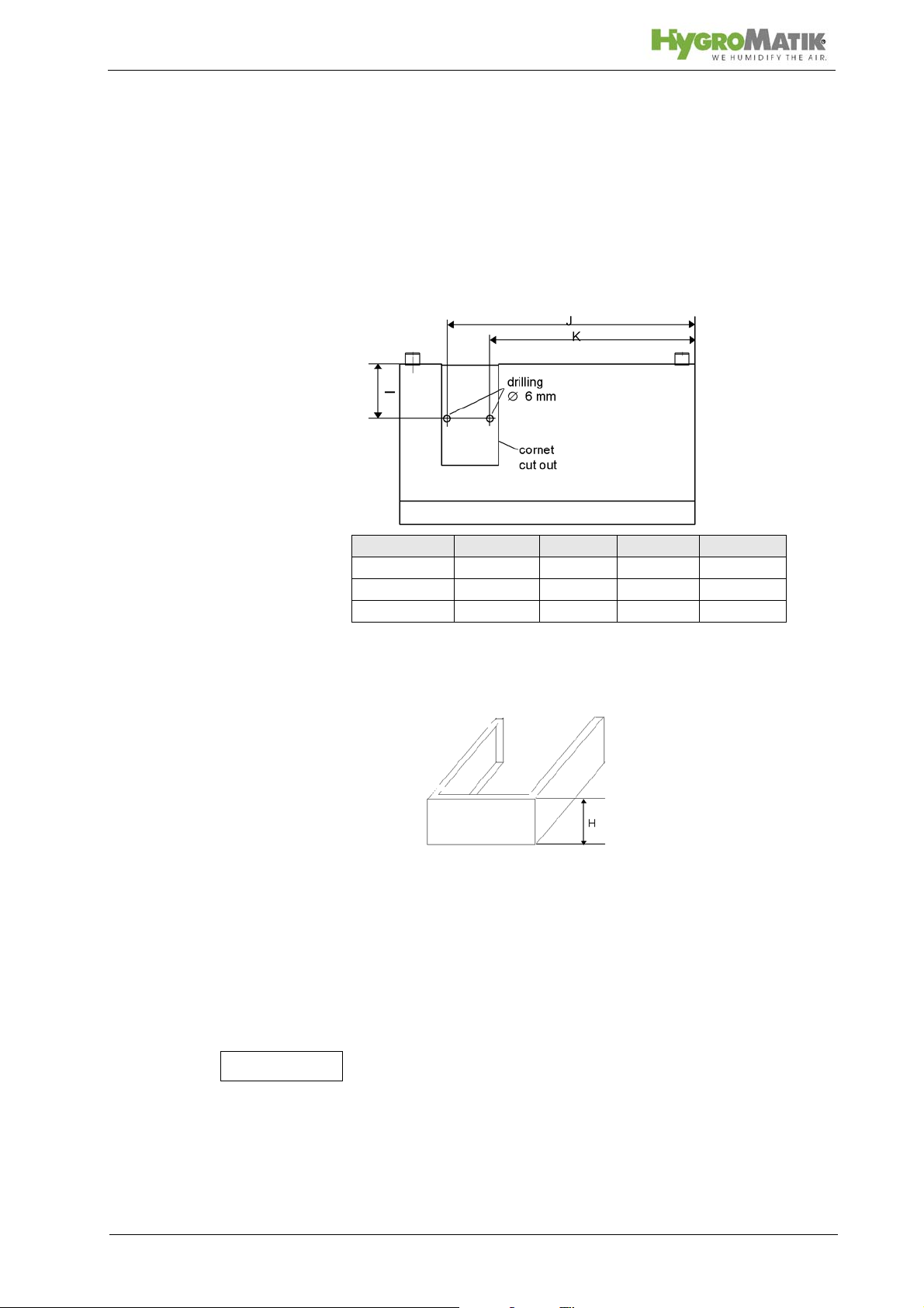
5.2.2 Fan Unit Cover
Covers for humidifier types HY05 and HY30 are optionally available to protect the steam and condensate hoses between the
steam humidifier and the fan unit. The vertical distance between
the humidifier and the fan unit is determined by the height of the
cover (see table of dimensions, H).
» Drill two holes in the housing as specified in the follo-
wing diagram.
Unit type H [in/mm] I [in/mm] J [in/mm] K [in/mm]
HY05-HY08 6.9/175 3.1/80 14.7/373 10.5/266,5
HY13-HY23 11/280 4.1/105 16.6/422 12.2/310
HY30 11/280 4.1/105 17.8/452 13.4/340
» Install the steam humidifier and fan unit on the wall at a
distance given by the front cover (measure H).
» Secure the steam hose between the humidifier and fan
unit with hose clamps.
» Also using a hose clamp, attach the condensate hose
to the fan unit.
» Run condensate hose along the rear of the unit to the
water discharge (see also chapter "Water Discharge").
» Lay the condensate hose with a 200 mm loop directly
over the drain. The loop acts as a vapor barrier.
Condensate cannot be fed back into the steam cylinder.
» Slide cover between humidifier and fan unit.
» Fasten cover with the two screws supplied. Screw from
the steam panel outwards.
Page 22
o
D
m
5.3 Absorption Distance BN
The "absorption distance" (BN) is defined as the distance from
the steam feed to where the steam is completely absorbed in the
treated air. Within the absorption distance, steam is visible as
mist in the air stream.
Condensation may occur on anything installed within the
absorption distance.
Although steam outside the absorption distance (B
) is com-
N
pletely absorbed, it is not yet evenly diffused in the duct. If you
plan to install any parts or devices inside the absorption distance, such as sensors or elbows, we recommend increasing
the absorption distance using the formulae below. The absorption distances required for certain installed fittings are distinguished by separate symbols and calculated as a multiplier of
the absorption distance B
.
N
Absorption Distance
B
N
for normal obstructions, such as sensors, ventilators, outlets
B
= (1,5...2) x BNfor fine filters, heat registers
c
B
= (2,5...3) x BNfor particle filters
s
B
= (3...5) x B
d
for humidity sensors, duct humidistats
N
The absorption distance has no fixed value, but depends on
many factors. These are depicted in the absorption distance
nomogram below.
5.3.1 Determining the Absorption Distance
To determine the absorption distance, the following parameters
are required:
• Air humidity before humidification x
• Air temperature after humidification t
humidifiers the change in air temperature due to humidification may be disregarded t
1
• Specific increase in humidity x in g/kg (can be determined in the h,x diagram)
• quantity of steam introduced in kg/h.
• air speed w
• Total length l
in m/s in air duct
L
of the steam manifold installed in the air
D
duct
1
or t2).
in g/kg.
in °C (with steam
2
Page 23

Air humidity before humidification
Air temperature after humidification
Specific increase in humidity
quantity of steam introduced
air speed t
Total length of the steam manifold
o
D
m
Length ID of the usable steam manifold depends on the dimensions of the air duct. The length of the absorption distance can
be reduced by using multiple steam manifolds (also see section
on the steam manifold).
Method:
Graphically determine absorption distance B
using the absorp-
N
tion distance nomogram (also see Section „Absorption Distance
Nomogramm“). Enter the value of the parameters enumerated
above into the respective quadrants. The resulting point of intersection indicates the value of the desired absorption distance
B
.
N
Notes:
x
: _______________________________[g/kg]
1
: _______________________________[°C]
t
2
x:_______________________________[g/kg]
:_______________________________[kg/h]
w
: _______________________________[m/s]
L
: _______________________________[mm]
l
D
Page 24
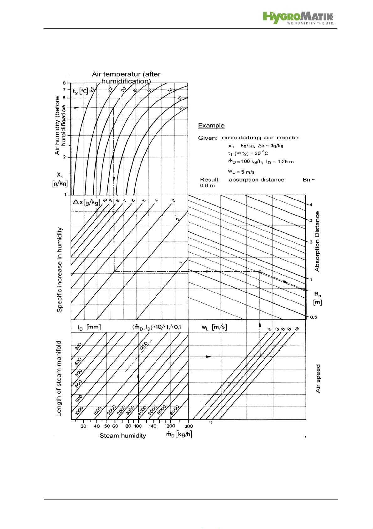
5.3.2 Absorption Distance Nomogram
Source: Henne, Erich: Luftbefeuchtung (Air Humidification), 3rd Edition 1984 (Page 101), Oldenbourg Industrieverlag, Munich
Page 25
 Loading...