

HygroMatik HeaterCompact User Manual
Electric Heater Steam Humidifier
HeaterCompact
Installation yellow
Plumbing blue
Electrics red
Maintenance green
General Information white
Manual

Page 2
Warning, Hazardous Voltage: All work to be performed by trained personnel only.
All electrical installation and servicing of the electrical components of this unit to be
performed by qualified electricians only. Disconnect power supply before installation
and servicing!
Copyright HYGROMATIK GmbH; HeaterCompact January 2012
Information in this manual is subject to change or alteration without prior notice.
Current version of this manual can be found at: www.hygromatik.co.uk

Page 3
1. Introduction ....................................................................................................................... 5
1.1 Typographic Distinctions ...................................................................................................5
1.2 Documentation .................................................................................................................. 5
1.3 Directions for Use ..............................................................................................................6
2. Safety Notes ....................................................................................................................... 7
2.1 Overview ........................................................................................................................... 7
2.2 Guidelines for Safe Operation ........................................................................................... 7
2.3 Disposal after Dismantling .................................................................................................8
3. Transport ............................................................................................................................ 9
3.1 Overwiew ...........................................................................................................................9
3.2 Transport Size and Weigth ................................................................................................ 9
3.3 Packing ..............................................................................................................................9
3.4 Interim Storage ..................................................................................................................9
3.5 Check for Complete and Correct Delivery of Goods .........................................................9
3.6 Included in the Delivery .....................................................................................................10
4. Operation and Device Construction ................................................................................ 11
4.1 Mode of Action .................................................................................................................. 11
4.2 Installation and Method of Operation ................................................................................ 12
4.3 Internal Output Setting ...................................................................................................... 14
5. Mechanical Installation .....................................................................................................15
5.1 Steam Humidifier - environmental conditions .................................................................... 15
5.1.1 Equipment Dimensions HC ............................................................................................16
5.1.2 Fitting Measures .............................................................................................................18
5.2 Absorption Distance BN ....................................................................................................19
5.2.1 Determining the Absorption Distance ............................................................................. 19
5.3 Fan Unit (option) ................................................................................................................ 21
5.3.1 Fan Unit Type VG ...........................................................................................................21
5.3.2 Absorption Distance Nomogram .................................................................................... 23
5.4 Steam Manifold .................................................................................................................24
5.4.1 Notes on Installation ....................................................................................................... 24
5.5 Steam Line ........................................................................................................................ 28
5.6 Cover Plate ........................................................................................................................ 29
5.7 Drill Pattern ........................................................................................................................ 30
5.8 Condensate Hose .............................................................................................................. 32
5.9 Types of Installation ..........................................................................................................32
5.10 Steam Solenoid Valves ...................................................................................................34
5.11 Unit Installation Check ..................................................................................................... 34
6. Water Installation ..............................................................................................................35
6.1 Water Quality ..................................................................................................................... 35
6.2 Water Supply (For Operation with Tap Water or Partially Softened Water) ...................... 37
6.2.1 Feed from Holding Tank ................................................................................................. 38
6.3 Water Treatment ...............................................................................................................38

Page 4
6.4 Water Discharge ............................................................................................................... 39
6.5 Checklist ............................................................................................................................40
7. Electrical Installation ........................................................................................................ 41
7.1 Electrical Installation .......................................................................................................... 41
7.2 Safety Interlock .................................................................................................................. 42
7.3 Control Connection ............................................................................................................ 43
7.4 Control Connection - Steam Bath Application ...................................................................43
7.4.1 Temperature Sensor Connection ...................................................................................43
7.5 Control Connection - Air Conditioning Application ............................................................ 43
7.5.1 1-step control .................................................................................................................. 44
7.5.2 Proportional Control with an external control signal ....................................................... 44
7.5.3 Proportional Control with Built-In PI-Controller ..............................................................46
7.6 Cable Connections ............................................................................................................ 47
7.7 Fan Unit .............................................................................................................................47
7.8 Wiring Diagram .................................................................................................................. 48
7.9 Electrical Installation Checklist ..........................................................................................48
8. Maintenance ....................................................................................................................... 49
8.1 Maintenance for Operation with Demineralized Water / Condensate ............................... 50
8.2 Maintenance for Operation with Tap Water or Partially Softened Water ...........................51
8.3 Access to Control Unit .......................................................................................................52
8.4 Removing and Cleaning the Steam Cylinder .................................................................... 53
8.5 Maintenance of the Control Cylinder ................................................................................. 58
8.5.1 Cleaning the nozzle in the steam hose adapter .............................................................58
8.6 Replacing Heater Elements ............................................................................................... 58
8.7 Replacing Thermo Sensor (for Heater Element) ............................................................... 59
8.8 Unlocking of a Released Thermo Sensor (for heater element) ......................................... 60
8.9 Unlocking of a Released Thermo Sensor (for Solid State Relay) ..................................... 60
8.10 Removing Inlet Solenoid Valve and Cleaning Fine Mesh Filter ...................................... 61
8.11 Cleaning Blow-Down Pump .............................................................................................62
8.12 Cleaning connection hoses and cylinder base ................................................................ 63
8.13 Checking Cable Screw Connections, Heater Element Wires .......................................... 64
8.14 Operational Check ...........................................................................................................64
8.15 Dismantling ......................................................................................................................64
9. Commissioning ................................................................................................................. 65
10. EC-Declaration of Conformity ........................................................................................ 66
11. Spare Parts ...................................................................................................................... 67
12. Fax Form - Order for spare parts ................................................................................... 71
13. Index .................................................................................................................................72
14. Technical Specifications ................................................................................................ 74
15. Exploded View ................................................................................................................. 76
16. View of Cabinet ................................................................................................................ 77

Page 5
1. Introduction
Dear Customer,
Thank you for choosing a HygroMatik steam humidifier.
HygroMatik steam humidifiers represent the latest in humidifica-
tion technology.
They will impress you with their safety, ease of use and econom-
ical operation.
In order to operate your HygroMatik steam humidifier safely,
properly and efficiently, please read these operating instructions.
Employ your steam humidifier only in sound condition and as
directed. Consider potential hazards and safety issues and follow all the recommendations in these instructions.
If you have additional questions, please contact us:
Tel.: +49-(0)4193 / 895-0 (Main Number)
Tel.: +49-(0)4193 / 895-293 (Technical Support Hotline)
Fax: +49-(0)4193 / 895-33
e-mail: hot1@HygroMatik.de
For all technical questions or spare parts orders, please be prepared to provide unit type and serial number (see name plate on
the unit).
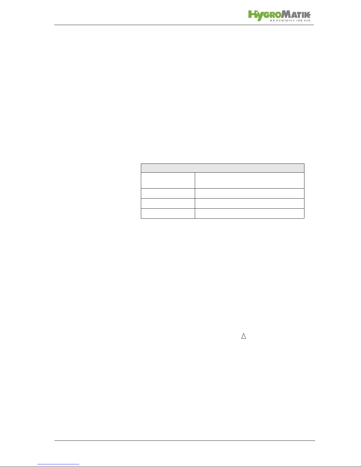
1.1 Typographic Distinctions
preceded by a bullet: general specifications.
» preceded by an arrow: Procedures for servicing or
maintenance which should or must be performed in the
indicated order.
Installation step which must be checked off.
italics Terms used with graphics or drawings.
1.2 Documentation
Retention
Please retain these operating instructions in a secure, always
accessible location. If the product is resold, turn the documentation over to the new operator . If the document ation is lost, please
contact HygroMatik.
Versions in Other Languages
These operating instructions are available in several languages.
If interested, please contact HygroMatik or your HygroMatik
dealer.
Page 6
1.3 Directions for Use
The proven principle of heating water by the use of electric
immersion heaters is exploited to generate steam. Using different tap water qualities or partial softened water (all humidifier
types) or fully demineralized water / condensate water (only for
humidifier type HeaterLine, HeaterCompact and HeaterSlim).
Warning: HygroMatik steam humidifiers emit steam with a temperature of 100° C. The steam may not be inhaled directly.
Only qualified and authorised personnel may operate the unit.
Persons transporting or working on the unit , must have read
and understood the corresponding parts of the Operation and
Maintenance Instruction and especially the chapter 2. „Safety
Notes“. Additionally, operating personnel must be informed of
any possible dangers. You should place a copy of the Operation
and Maintenance Instruction at the unit‘s operational location (or
near the unit).
The steam humidifier is not qualified for exterior application.
Page 7
2. Safety Notes
2.1 Overview
These safety notes are required by law. They promote workplace safety and accident prevention.
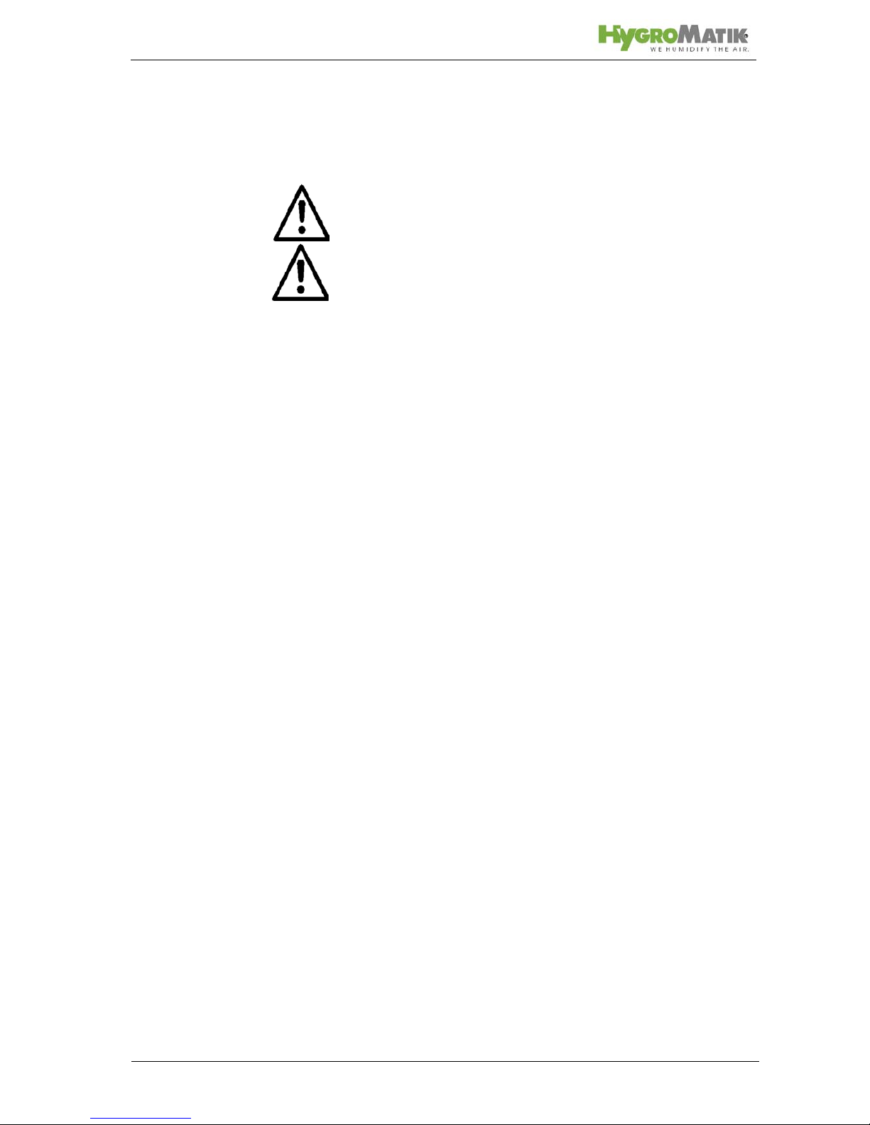
Warnings and Safety Symbols
The safety symbols below identify sections containing warnings
about hazards or potential dangers. Please familiarize yourself
with these symbols.
Warning: Failure to observe this warning may result in serious
injury or death and/or damage to the unit.
Danger, Hazardous Voltage: Hazardous electrical current!
Failure to observe this warning may result in injury or even seri-
ous injury or death.
Warning: Failure to follow these instructions may result in dam-
age to the unit due to electrostatic discharge. The electronic
components of the humidifier control are very sensitive to electrostatic discharges. In order to safeguard these components
during installation and servicing, steps must be taken to protect
against ESD.
Reminder: Materials and consumables must be handled and/or
disposed of as required by law.
Note: Appears before explanations or cross-references which
refer to other sections of the operating instructions.
2.2 Guidelines for Safe Operation
Overview
Obey all safety notes and warnings present on the unit. In case
of a malfunction, switch off the unit immediately and prevent a
restart. Repair malfunctions promptly. After any repair work,
have qualified personnel check the safe operation of the unit.
Use original spare parts only. Additional national safety regulations also fully apply to the operation of this unit.
This unit is not designed for the use by persons (also children)
with limited physical, sensory and mental abilities - or without
knowledge and experience. Unless they are supervised or trained by a person, who is responsible for their safety.
Supervise children in order to ensure that they will not play with
the unit.
The unit is only allowed to work with connected steam hose that
Page 8
safely leads the steam.
HygroMatik steam humidifiers are IP20-protected. Make sure
that the unit is protected from drips in its installed location.
Installing a humidifier in a room without water discharge requires
safety devices to protect against water leakages.
Accident Prevention Regulations
Comply with the Accident Prevention Regulation Electrical Systems and Equipment to prevent injury to yourself and others.
Operation of the Unit:
Do not perform any work which compromises the safety of the
unit. Regularly check that all safety and monitoring devices are
functioning normally. Do not remove or disable safety devices.
Installation, Dismantling, Maintenance and Repair of the
Unit:
Disconnect unit components from power supply prior to maintenance or repair work.
Attaching or installing additional components is permitted only
with the written consent of the manufacturer.
Electrical
Work on the electrical system must be performed by qualified
personnel.
Disconnect unit components from power supply prior to work.
It is not allowed to connect the unit to DC voltage supply.
In case of a malfunction in the electrical power supply, switch off
the unit immediately. Use only original fuses with the appropriate
amperage rating. Regularly check the unit's electrical equipment. Promptly repair any damage, such as loose connections,
burned wiring or defective electrical insulation. After proper electrical installation or repair, test all safety mechanisms (such as
grounding resistance).
2.3 Disposal after Dismantling
Note: The operator is responsible for the disposal of unit compo-
nents as required by law.
Page 9
3. Transport
3.1 Overwiew
Note:Proceed carefully when transporting the steam humidifier in
order to prevent damage from rough or careless loading and unloading.
If the transport of this unit is attempted by only one person there
is a risk that the unit will drop down. We propose to transport the
unit by two persons.
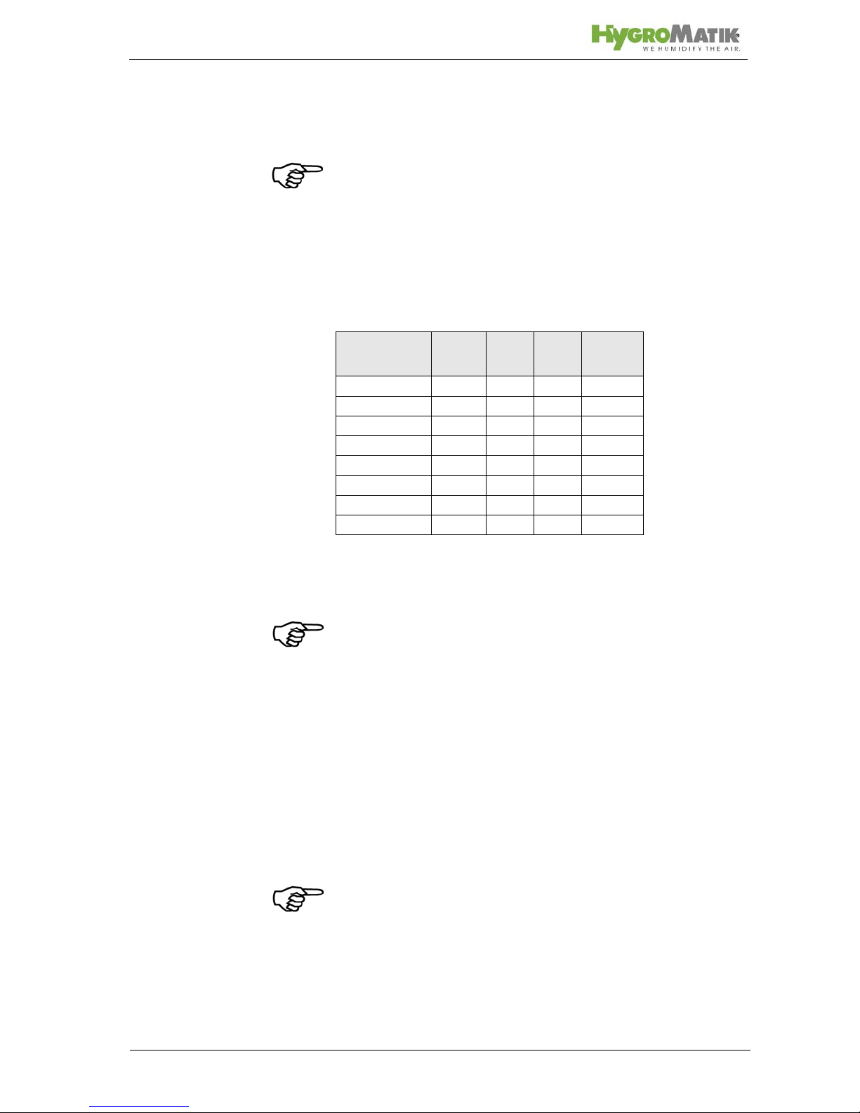
3.2 Transport Size and Weigth
* Dimensions and weigths can vary insignificantly
3.3 Packing
Note: Observe the symbols affixed to the box.
3.4 Interim Storage
Keep the unit dry and protect from frost.
3.5 Check for Complete and Correct Delivery of
Goods
Upon receipt of the unit, make sure that:
type and serial number on the name plate match what
is in the purchasing and delivery documents,
equipment is complete and in perfect condition.
Note: In case of damage during shipment and/or missing parts,
immediately file a written claim with your carrier or supplier.
Type* depth
[cm]
higth
[cm]
width
[cm]
weigth
[kg]
HC03 360 651 507 16
HC06 360 651 507 16
HC09 360 651 507 16
HC06P 410 775 584 25
HC09P 410 775 584 25
HC12 410 775 584 26
HC18 410 775 584 26
HC27 410 775 584 27
Page 10
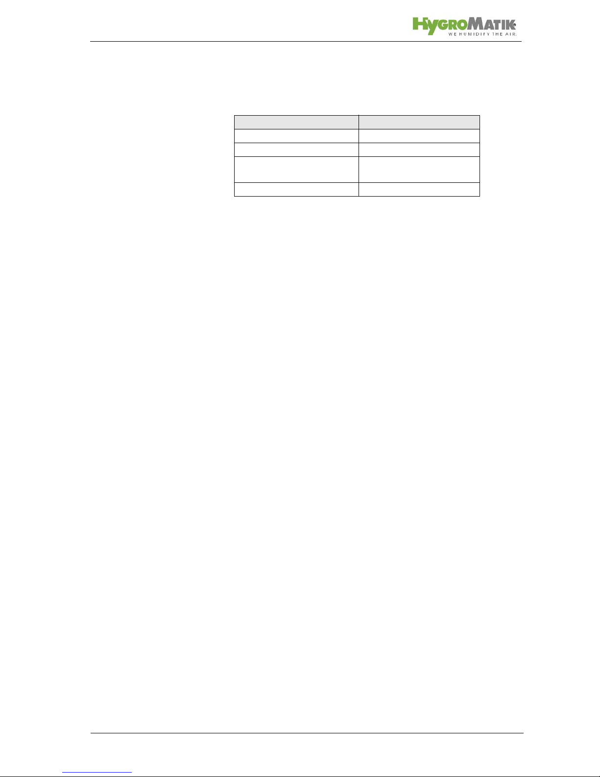
Time limits for filing freight claims with shipping companies are*:
* Subject to change without prior notice.
3.6 Included in the Delivery
The delivery includes:
• Unit of the selected humidifier type including selected control.
• Water installation hose.
• Manuals for the steam humidifier and the control.
• Ordered accessories (steam manifold, steam hose, condensate hose, etc.).
• Maintenance o-ring set for steam cylinder.
Transport Company After Receipt of Goods
Mail 24 hours at the latest
Rail 7 days at the latest
Truck and railway compa-
nies
4 days at the latest
Parcel Service immediatly

Page 11
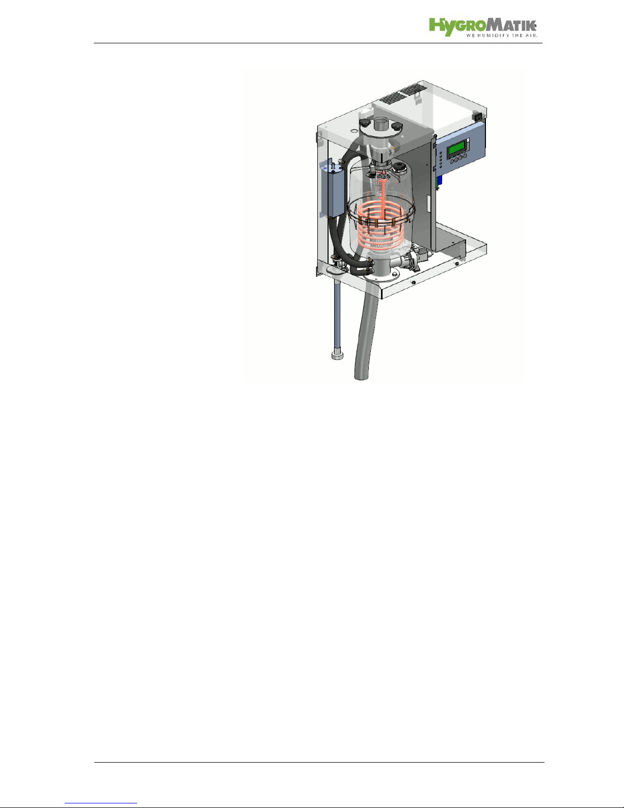
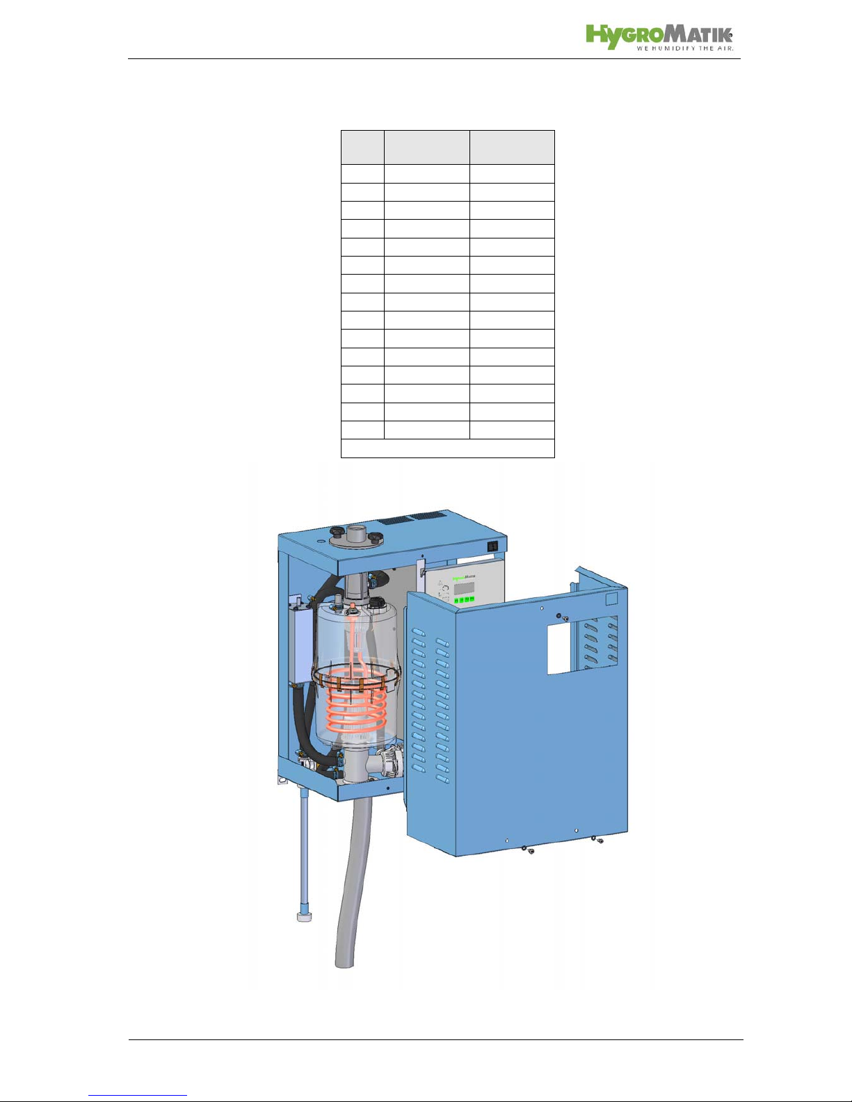
4. Operation and Device Construction
4.1 Mode of Action
The Imersion Heater Principle
One to three heater elements (Pos. 8 in the exploded view,
please see cover foldout) are placed in a closed cylinder and
connected to alternating current. The cylinder is filled with tap
water, fully demineralized water or partially softened water. Heat
generated by the heater element increases water temperature to
approx. 100°C.
When fully demineralized water is used, the feed water is practically free of minerals. This ensures long life for the cylinder and
heater elements since virtually no mineral deposits can settle or
build up. Fully demineralized water minimizes the number of service / maintenance checks.
When tap water is used, some of the minerals dissolved in the
water will settle in the cylinder as solids of various compositions.
Most of these scale deposits are removed by periodic flushing or
use of a heavy-duty blow-down pump. See section "Servicing
During Operation with Tap Water".
The generated steam has a temperature of about 100°C and
minimal positive pressure ("pressureless” steam). It is virtually
demineralized and germ-free.

Page 12
4.2 Installation and Method of Operation
By pressing the control switch („Pos. I”) the humidifier is turned
on. When the hygrostat or controller signals a demand for
humidification, the inlet solenoid valve (14) opens. The solenoid
valve is designed for pressures from 100 x 10
3
to 100 x 104 Pas-
cals (1 to 10 bar).
Water is fed into the cylinder.
The water level in the cylinder must be maintained within a spec-
ified range. If the water level is too high, the ellbow acts as a
safety overflow for water drainage. If the water level is too low, it
could cause the heater element (8) to overheat. Therefore,
power supply to the heater element is shut off when water levels
are too low.
The cylinder water level is controlled by a level control (27). The
level control consists of a stainless steel cylinder with two float
switches and three reed contacts. The float switches indicate the
water level in the steam cylinder: "Dry Run", "Humidification"
and "Max. Level". The control capsule is pressure-equalized.
At the standard setting, the inlet solenoid valve (14) opens when
the water level remains below “humidification” level for 10 seconds. The water level then rises again to “humidification” level.
The steam cylinder consists of a top (16) and lower (9) part
joined with a cylinder flange. The seal between the cylinder and
cylinder base (11), as well as between the top and lower part of
the cylinder, is maintained using an o-ring.
Page 13
General survey
The heater elements are equipped with a mechanical high temperature safety. This mechanism provides a redundant safety
system in the event of excessively low water levels (“Dry Run”).
The cylinder water is periodically flushed out with a heavy-duty
blow-down pump (10).
Steam is fed into air-conditioning ducts through special steam
hoses and steam manifolds. Under normal conditions, this
steam has virtually no heating effect on the air to be humidified.
Accumulated condensate can be returned to the steam cylinder
via a condensate hose.
Direct room humidification (without ducts) is performed using fan
units (with blower and nozzle). The steam generator is connected to the fan unit with steam and condensate hoses.
Page 14
Steam lines in steam bath cabins employ special steam hoses
and piping (if required). Accumulated condensate is normally
routed into the steam cabin. At a relative humidity of 100%, the
supplied steam is used to heat the steam bath.
Warning: Leakage of the steam cylinder can cause a serious
hazard, such as giving an electric shock.
Warning: During blow down hot water with a temperature of
about 95°C is being drained. This can cause burns to the skin at
direct contact.
4.3 Internal Output Setting
Continuous control of the HeaterCompact Type steam humidifier
is achieved by proportional control of the heater element s. In this
way the humidifier can be proportionally operated across the
entire output range of 5% - 100% nominal capacity.
Page 15
5. Mechanical Installation
Warning: Installation of this unit should be performed by quali-
fied personnel only. Hygromatik accept no liability for damage
due to faulty installation.
Obey all safety instructions and warnings on the unit. During
installation the unit must be disconnected from its power supply.
Accessory equipment may not be installed on or in the unit without prior written consent from HYGROMATIK. Otherwise the
warranty is void.
Warning: If the installation of this unit is attempted by only one
person there is a risk that the unit will drop down. We propose to
carry out the installation by two persons.
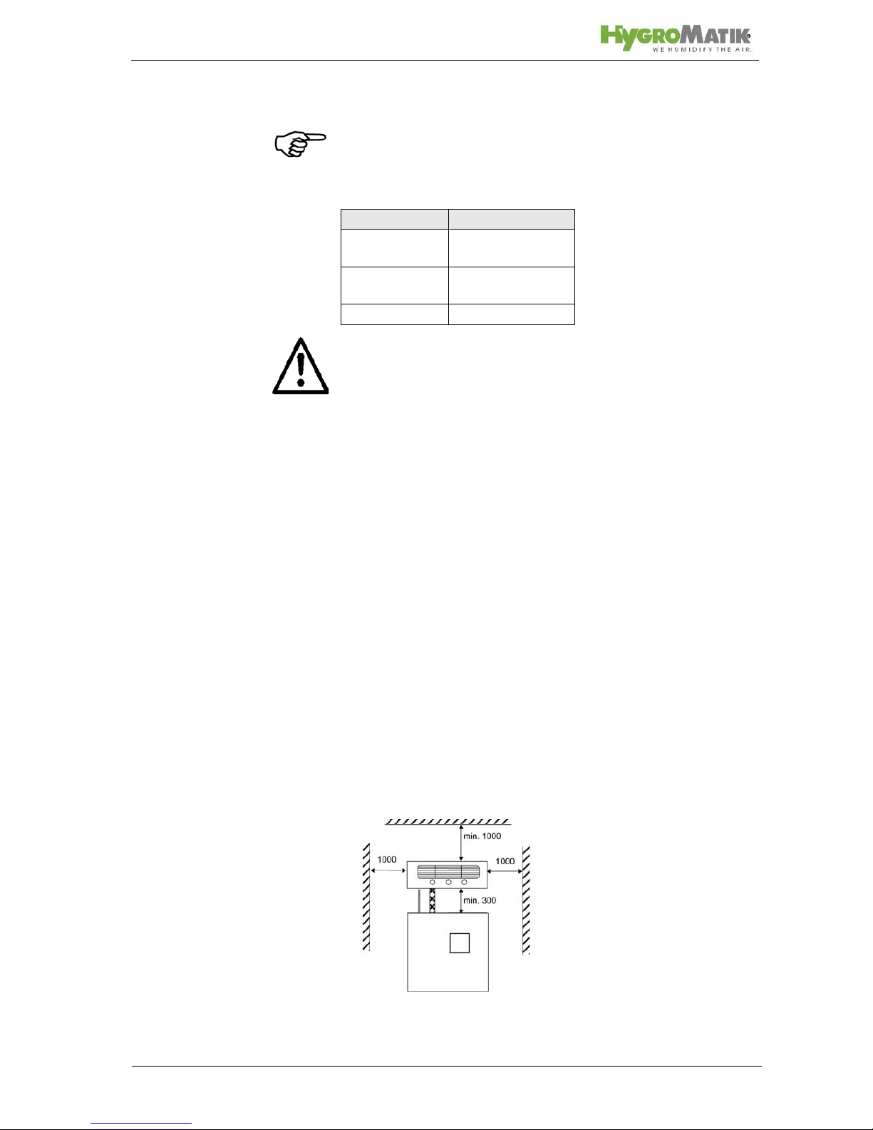
5.1 Steam Humidifier - environmental conditions
Note: When selecting the location for steam humidifier installa-
tion, be aware of the following:
Ambient temperature must be between +5 and +40 °C.
Relative humidity may not exceed 80% RH.
Observe clearances specified in the diagrams below to
ensure adequate ventilation.
An Installation in a closed room requires aeration and if
neccessary temperature conditioning in order to reach
the above mentioned environmental conditions.
HygroMatik humidifiers are not suitable for direct out-
door installation.
Install the steam humidifier as close as possible to the
steam manifold. Use only short lengths of steam and
condensate hose to ensure optimal performance.
Hoses must be laid at a constant 5-10% grade to uni-
formly prevent sags and kinks.
The back surface of the steam humidifier heats up dur-
ing operation (to max. 70°C). Take care that the construction on which the unit is mounted is not made of
temperature-sensitive material.
Place the steam humidifier so that the unit is easily
accessible with sufficient space to perform maintenance.
The unit’s protection class is IP20.
Page 16
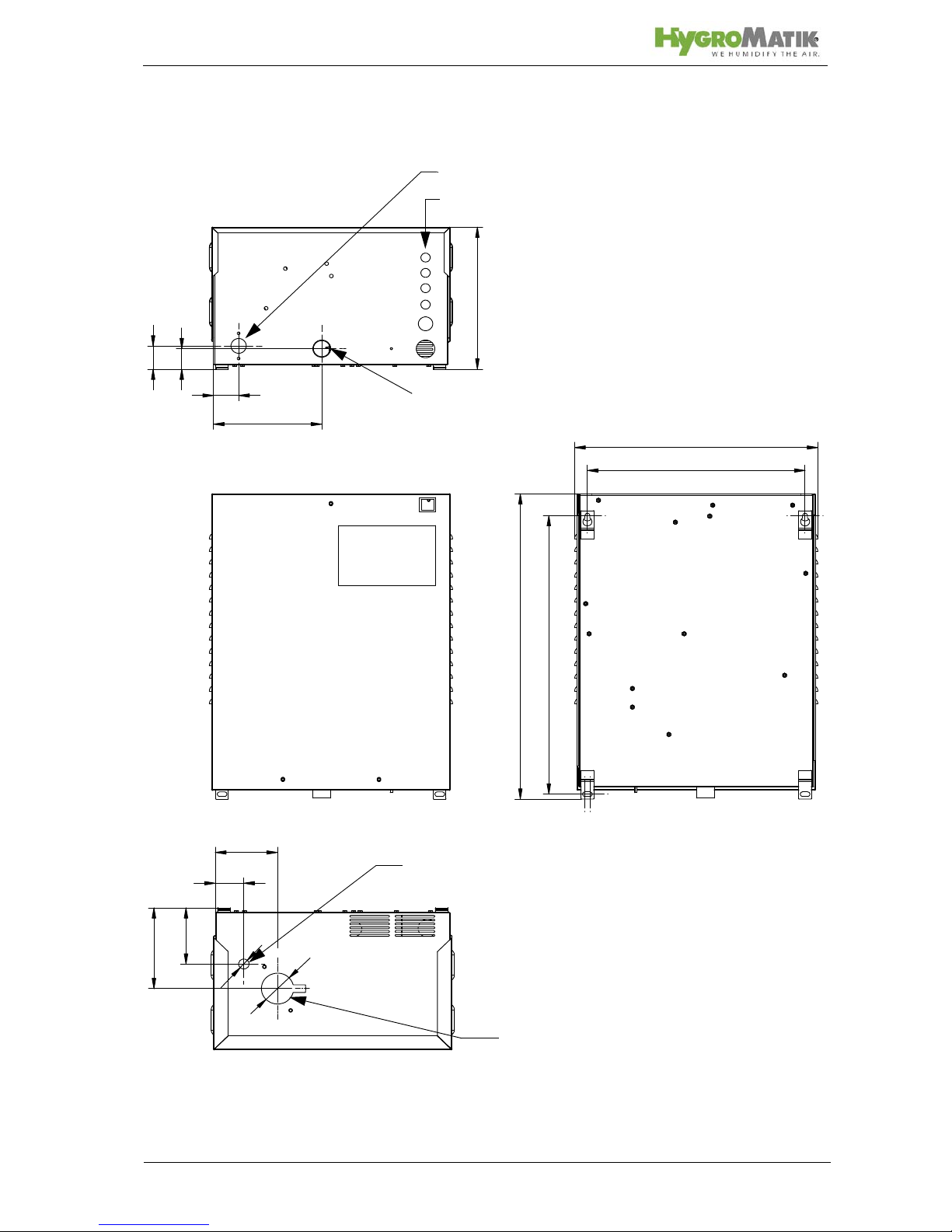
5.1.1 Equipment Dimensions HC
c
a
e
l
j
m
k
o
n
d
b
h
f
i
g
View from below
Rear view
View from top
Water inlet
Waste water connection
Steam outlet
Condensate inlet
Cable entries
Page 17
HC03-09 HC06P-09P
HC12-HC27
a 562 707
b 427 490
c 257 306
d 382 445
e 513 657
f30 30
g 190 250
h35 50
i44 50
j 145 162
k 109 138
l100 81
m50 86
n56 56
o18 18
all dimensions in mm
General Survey
Page 18
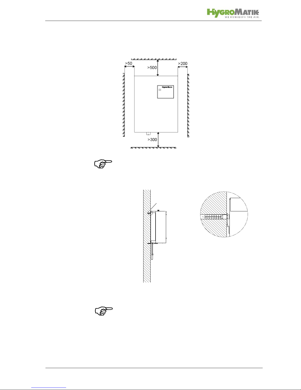
5.1.2 Fitting Measures
Wall Distance
Note: It is often advantageous to use existing water conn ections
(feed and drain) when selecting the steam humidifier.
Wall Mounting
Note: To function properly the steam humidifier must be installed
vertically.
Measures for drills for wall mounting please see table (measures
d and e) in chapter „Equipment Dimensions”.If there is no suitable wall, it is recommended that the equipment is installed on
brackets which can be embedded in the floor.
(all dimensions in mm)
B
B
Page 19
5.2 Absorption Distance BN
The "absorption distance" (BN) is defined as the distance from
the steam feed to where the steam is completely absorbed in the
treated air. Inside the absorption distance, steam is visible as
mist in the air stream.
Condensation may collect on anything installed inside the
absorption distance.
Although steam outside the absorption distance (B
N
) is com-
pletely absorbed, it is not yet evenly diffused in the duct. If you
plan to install any parts or devices inside the absorption distance, such as sensors or elbows, we recommend increasing
the absorption distance using the formulae below. The absorption distances required for certain installed fittings are distinguished by separate symbols and calculated as a multiplier of
the absorption distance B
N
.
The absorption distance has no fixed value, but depends on
many factors. These are depicted in the absorption distance
nomogram below.
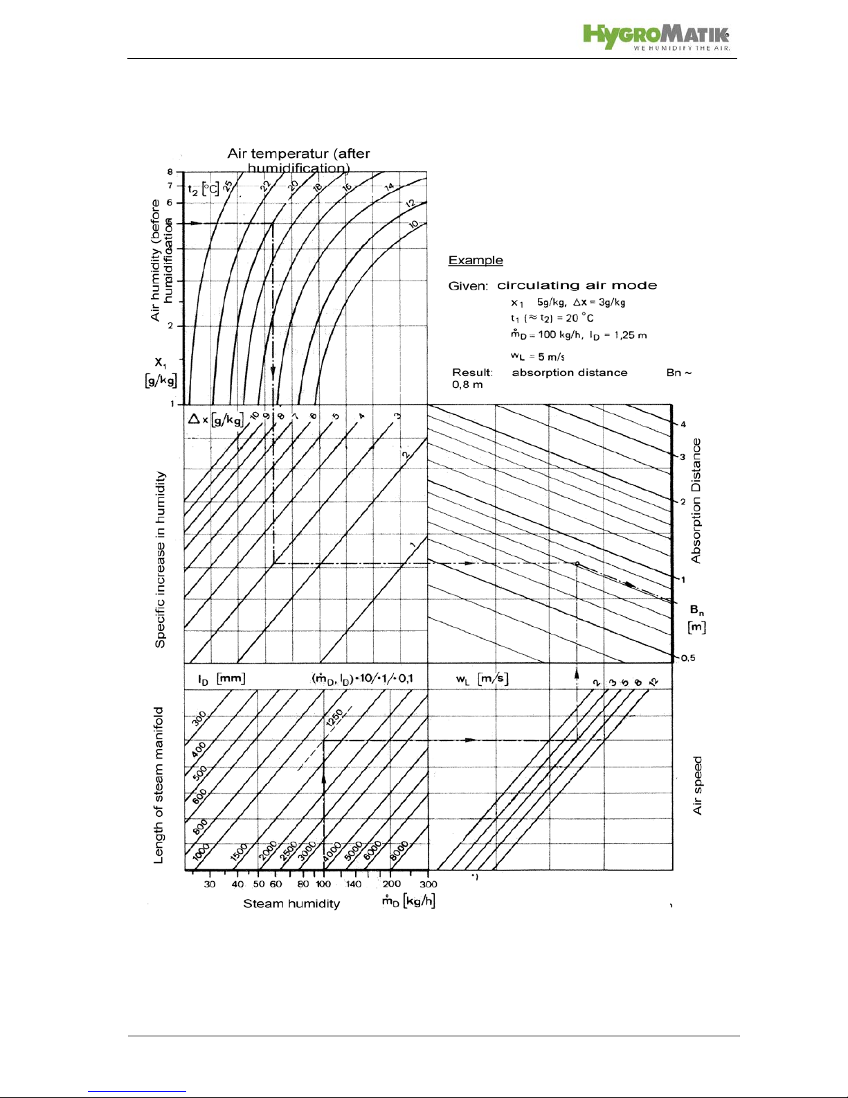
5.2.1 Determining the Absorption Distance
To determine the absorption distance, the following parameters
are required:
Air humidity before humidification x
1
in g/kg.
Air temperature after humidification t
2
in °C (with steam
humidifiers the change in air temperature due to humidification may be disregarded t
1
or t2).
Specific increase in humidity x in g/kg (can be deter-
mined in the h,x diagram)
quantity of steam introduced in kg/h.
air speed w
L
in m/s in air duct
Total length l
D
of the steam manifold installed in the air
duct
Absorption Distance
B
N
for normal obstructions, such as sensors, ventilators, outlets
B
c
= (1,5...2) x BNfor fine filters, heat registers
B
s
= (2,5...3) x BNfor particle filters
B
d
= (2,5...3) x BNfor humidity sensors, duct humidistats
o
D
m

Page 20
Length ID of the usable steam manifold depends on the dimensions of the air duct. The length of the absorption distance can
be reduced by using multiple steam manifolds (also see section
on the steam manifold).
Method:
Graphically determine absorption distance B
N
using the absorp-
tion distance nomogram (also see Section „Absorption Distance
Nomogramm“). Enter the value of the parameters enumerated
above into the respective quadrants. The resulting point of intersection indicates the value of the desired absorption distance
B
N
.
Notes:
x
1
: _______________________________[g/kg]
t
2
: _______________________________[°C]
x:_______________________________[g/kg]
:_______________________________[kg/h]
w
L
: _______________________________[m/s]
l
D
: _______________________________[mm]
Air humidity before humidification
Air temperature after humidification
Specific increase in humidity
quantity of steam introduced
air speed t
Total length of the steam manifold
o
D
m
Page 21
5.3 Fan Unit (option)
Note: The fan unit should be positioned to avoid drafts. A mini-
mum height of 2 m is generally sufficient.
Install the fan unit directly on a wall.
Warning:
During operation and some time afterwards the steam
nozzle is hot! This can cause burns to the skin at direct
contact.
During operation the cross-flow fan rotates. Do not
touch the fan during operation.
During operation hot steam discharges from the nozzle.
In the field of the visible steam cloud contact can cause
burns to the skin.
During operation the cross-flow fan rotates. Do not
touch the fan during operation.
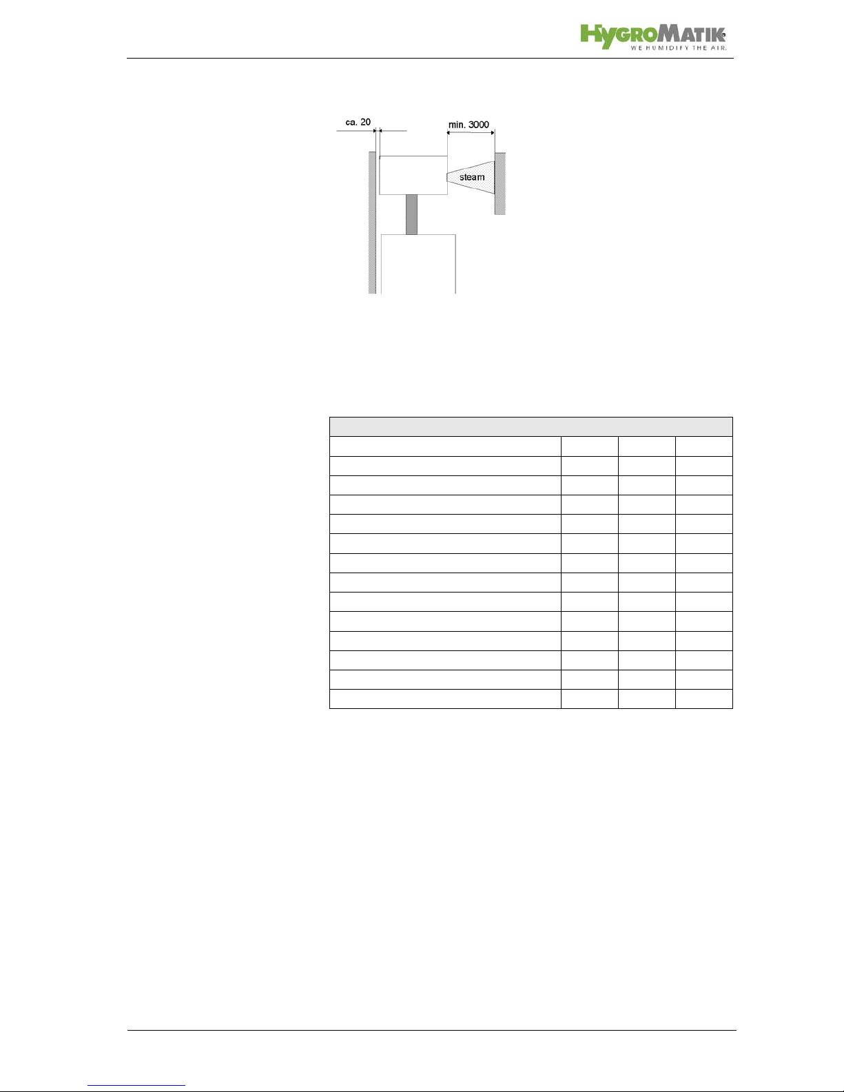
5.3.1 Fan Unit Type VG
The fan unit is installed above the steam humidifier.
When using multiple fan units, do not exceed a maxi-
mum distance of 5 m from the steam humidifier.
Observe the clearances specified in the diagrams
below.
Type Fan Unit
HC03,
HC06(P)
VG 08
HC09(P),
HC12
VG 17
HC18 - 27 VG 30
(all dimensions in mm)
Page 22
Fan unit, wall installation
Side view, wall-mounted fan unit
Technical Specifications Fan Unit VG
Fan Unit VG08 VG17 VG30
Quantity of Steam [kg/h] 8 17 30
Steam Inlet [mm]25 25 40
Condensate Outlet [mm]12 12 12
Airflow Capacity [cbm/h] 185 185 350
Nominal Output [W] 35 35 67
Nominal voltage [V] 230 230 230
Dimensions W [mm] 441 507 550
H [mm] 171 171 171
D [mm] 180 237 277
Weight [kg] 4,5 6 7
Page 23
5.3.2 Absorption Distance Nomogram
Source: Henne, Erich: Luftbefeuchtung (Air Humidification), 3rd Edition 1984 (Page 101), Oldenbourg Industrieverlag, Munich
Page 24
5.4 Steam Manifold
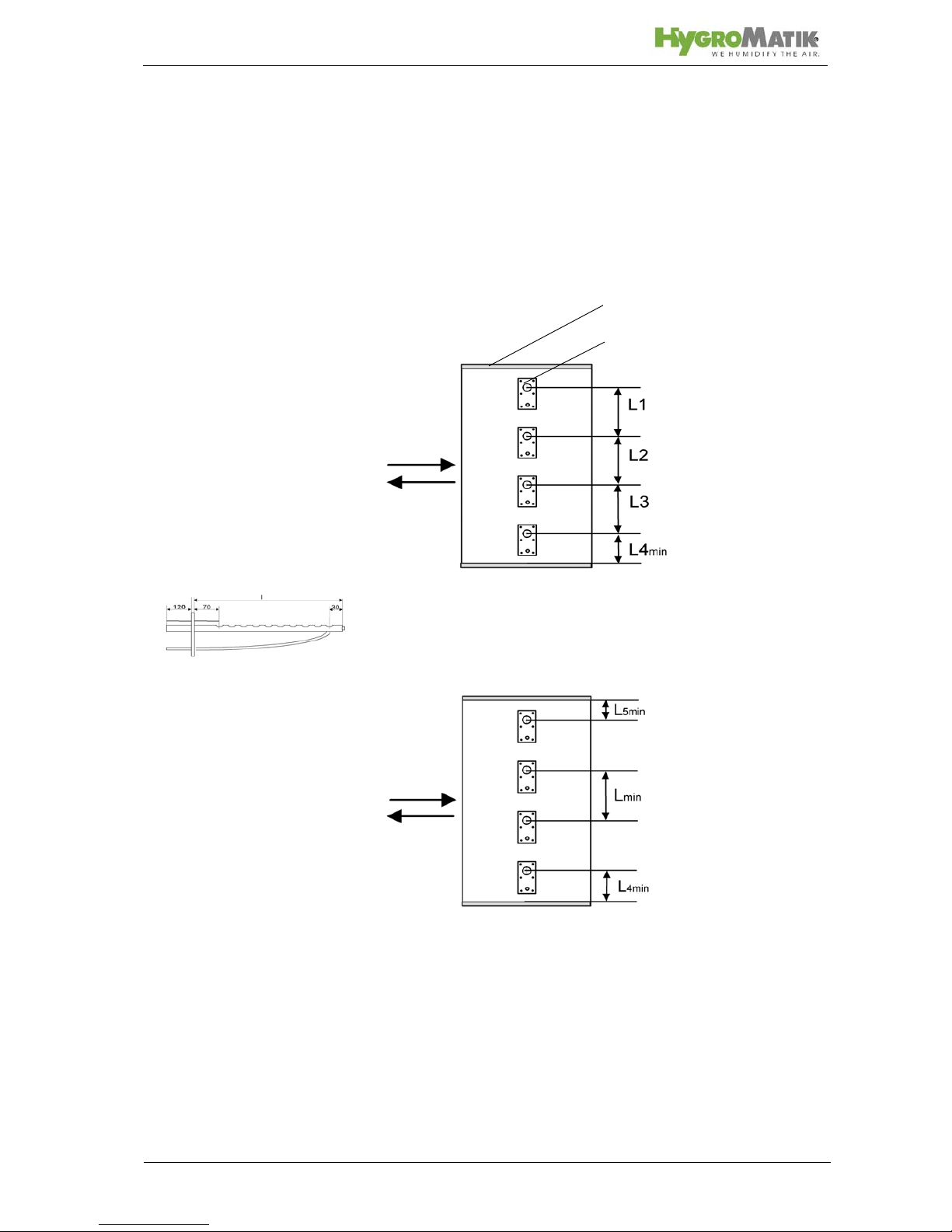
5.4.1 Notes on Installation
These notes are based on a homogeneous
Standard steam manifold installation:
An even distribution of steam manifolds ensures a uniform steam
distribution.
Please use the total hight of the duct!
Minimum distances in order to avoid condensation:
L
min = 210mm: distance „ steam manifold - next steam mani-
fold“
L4
min = 120mm: distance „lowest steam manifold - duct bot-
tom“:L5
min = 120mm: distance „highest steam manifold - duct
ceiling“Installations depending on special designs of air ducts:
Horizontal installation of
steam manifold
Steam Manifold
L1=L2=L3
Duct
Steam Manifold
Air flow
Air flow
direction
 Loading...