

HygroMatik FlexLine Plus, FLP15, FLP05, FLP25, FLP30 Series Manual
...
FlexLine Plus
Electric Heater Steam Humidifiers
ÁFLP.ENcÈ
FLP.EN
E-8881170
Manual
Certain computer programs contained in this product [or device] were developed by HygroMatik
GmbH ("the Work(s)").
Copyright © HygroMatik GmbH [03.12.2018]
FlexLine FLP 05/08/15/25/30/40/50 EN
All Rights reserved.
Current version of this manual can be found at: www.hygromatik.co.uk
HygroMatik GmbH grants the legal user of this product [or device] the right to use the Work(s)
solely within the scope of the legitimate operation of the product [or device]. No other right is
granted under this licence. In particular and without prejudice to the generality of the foregoing,
the Work(s) may not be used, sold, licensed, transferred, copied or reproduced in whole or in
part or in any manner or form other than as expressly granted here without the prior written consent of HygroMatik GmbH.
Information in this manual is subject to change or alteration without prior notice.
:$51,1*
Risk of electrical shock!
Hazardous electrical high voltage!
All electrical work to be performed by certified expert staff (electricians or expert personnel with
eqivalent training) only.
Page 2

1. Introduction ....................................................................................................................... 5
1.1 Typographic Distinctions ................................................................................................... 5
1.2 Documentation .................................................................................................................. 5
1.3 Symbols in Use ................................................................................................................. 5
1.3.1 Specific Symbols related to Safety Instructions ............................................................. 5
1.3.2 General Symbols ............................................................................................................ 5
1.4 Intended Use ..................................................................................................................... 6
2. Safety Instructions ............................................................................................................ 7
2.1 Guidelines for Safe Operation ........................................................................................... 7
2.1.1 Scope ............................................................................................................................. 7
2.1.2 Unit control ..................................................................................................................... 7
2.1.3 Unit Operation ................................................................................................................ 7
2.1.4 Mounting, dismantling, maintenance and repair of the unit ............................................ 8
2.1.5 Electrical ......................................................................................................................... 8
2.2 Disposal after dismantling ................................................................................................ 8
3. Transport ............................................................................................................................ 9
3.1 Overview ........................................................................................................................... 9
3.2 Packing .............................................................................................................................. 9
3.3 Interim Storage .................................................................................................................. 9
3.4 Check for Complete and Correct Delivery of Goods ......................................................... 9
4. Functional Description and Device Composition .......................................................... 10
4.1 Mode of Action .................................................................................................................. 10
4.2 Operational sequence ....................................................................................................... 11
4.3 Internal Output Setting ...................................................................................................... 11
4.4 Mechanical Construction ...................................................................................................11
4.4.1 FlexLine Plus .................................................................................................................. 11
4.4.2 FlexLine Process ............................................................................................................ 11
4.5 Thermal fuses .................................................................................................................... 12
5. Mechanical installation ..................................................................................................... 13
5.1 Environment Parameters to be met and Mounting Recommendations ............................. 13
5.1.1 Dimensions and Mounting Directions ............................................................................. 14
5.2 Unit Installation Check ....................................................................................................... 17
5.3 Absorption Distance BN ....................................................................................................18
5.3.1 Determining the Absorption Distance ............................................................................. 18
5.3.2 Absorption Distance Nomogram .................................................................................... 19
5.4 Steam Manifold ................................................................................................................. 20
5.4.1 General installation guidelines ....................................................................................... 20
5.4.2 Recommendations for dimensioning .............................................................................. 20
5.5 Steam line and condensate hose layout .......................................................................... 23
5.5.1 Guide lines for steam line design .................................................................................. 23
5.5.2 Condensate hose layout ................................................................................................. 23
5.5.3 Steam line and condensate hose installation types ....................................................... 24
Page 3

6. Water connection .............................................................................................................. 25
6.1 Water supply ..................................................................................................................... 25
6.2 Water discharge ................................................................................................................ 27
6.3 Water connections final check ........................................................................................... 28
7. Electrical connection ........................................................................................................ 29
7.1 Electrical installation approach ..........................................................................................29
7.2 Cable connections ............................................................................................................. 30
7.3 Safety interlock .................................................................................................................. 31
7.4 Connection diagrams ........................................................................................................ 31
7.5 Electrical installation check list .......................................................................................... 31
8. Commissioning ................................................................................................................. 32
9. Maintenance ....................................................................................................................... 33
9.1 General .............................................................................................................................. 33
9.1.1 Service messages .......................................................................................................... 33
9.1.2 Service messages for preventive maintenance .............................................................. 33
9.1.3 Safety instructions for maintenance ............................................................................... 34
9.2 Maintenance frame work when unit is operated with fully demineralised water and condensate
................................................................................................................................................. 35
9.3 Maintenance when unit is operated with tap water or partially softened water ................ 35
9.4 Removing and cleaning the steam cylinder ....................................................................... 36
9.4.1 Perform leakage check ...................................................................................................37
9.5 Cylinder base and strainer cleaning .................................................................................. 37
9.6 Steam cylinder and heater element cleaning .................................................................... 37
9.7 Cleaning Connection Hoses, Cylinder Base Connections, Steam Hose Adapter Nozzle . 38
9.8 Level control device cleaning ............................................................................................ 39
9.9 Heater element replacement ............................................................................................. 40
9.10 Releasing the thermical safety devices ........................................................................... 40
9.10.1 Variety of thermal protection devices in use ................................................................. 40
9.10.2 Unlocking of a thermo switch on the cylinder cover ..................................................... 41
9.10.3 Unlocking of the Klixon thermo switch .......................................................................... 41
9.11 Thermo switch replacement (for heater element) ............................................................ 41
9.12 Inspection of wiring connections and heater element wiring ........................................... 42
9.13 Removal and reinstallation of the twin solenoid valve including fine filter cleaning ........ 43
9.14 Removal and reinstallation of the quadruple solenoid valve including fine filter cleaning (Flex-
Line Process) .......................................................................................................................... 44
9.15 Cleaning of blow-down pump .......................................................................................... 45
9.16 Inspection of hoses ......................................................................................................... 45
9.17 Functional check ............................................................................................................. 45
9.18 Completion of maintenance ............................................................................................. 45
10. Dismantling ..............................................................................................................
11. Declaration of Conformity .............................................................................................. 47
........ 46
12. Spare Parts ...................................................................................................................... 48
13. Technical specifications ................................................................................................. 50
14. Exploded view ................................................................................................................. 52
15. View of housing ............................................................................................................... 53
Page 4
3OHDVHQRWH
'$1*(5
:$51,1*
127,&(127,&(
3OHDVHQRWH
1. Introduction
Dear Customer,
Thank you for choosing a HygroMatik steam
humidifier.
HygroMatik steam humidifiers represent the
latest in humidification technology.
In order to operate your HygroMatik steam
humidifier safely, properly and efficiently,
please read these operating instructions.
Employ your steam humidifier only in sound
condition and as directed. Consider potential
hazards and safety issues and follow all the
recommendations in these instructions.
If you have additional questions, please contact your expert dealer.
For all technical questions or spare parts
orders, please be prepared to provide unit
type and serial number (see name plate on
the unit).
Versions in Other Languages
These operating instructions are available in
several languages. If interested, please contact HygroMatik or your HygroMatik dealer.
1.3 Symbols in Use
1.3.1 Specific Symbols related to Safety Instructions
According to EN 82079-1 (and ANSI Z535.6),
the following signal words are used within
this document:
DANGER indicates a hazardous situation
which, if not avoided, will result in death or
serious injury.
1.1 Typographic Distinctions
• preceded by a bullet: general specifications
» preceded by an arrow: Procedures
for servicing or maintenance which
should or must be performed in the
indicated order
Installation step which must be
checked off.
italics Terms used with graphics or draw-
ings
1.2 Documentation
In addition to this manual, the appropriate
FlexLine Control documentation is mandatory
for the operation of the unit.
WARNING indicates a hazardous situation
which, if not avoided, could result in death or
serious injury.
&$87,21
CAUTION indicates a hazardous situation
which, if not avoided, could result in minor or
moderate injury.
NOTICE is used to address practices not
related to physical injury.
1.3.2 General Symbols
This symbol is used whenever a situation
requires special attention beyond the scope
of safety instructions.
Retention
Please retain these operating instructions in
a secure, always accessible location. If the
product is resold, turn the documentation
over to the new operator. If the documentation is lost, please contact HygroMatik.
Page 5
1.4 Intended Use
HygroMatik electric heater steam humidifiers
serve for steam production based on tap
water, partially softened water or fully desalinated water/cleaned condensate.
Proper usage also comprises the adherence
to the conditions specified by HygroMatik for:
• installation
• dismantling
• reassembly
• commissioning
• operation
• maintenance
• disposal.
Only qualified personnel may operate the
unit. Persons transporting or working on the
unit must have read and understood the corresponding parts of the Operation and Maintenance Instructions and especially the
chapter 2. „Safety Notes“.
Additionally, operating personnel must be
informed of any possible dangers by the provider. A copy of this manual is to be placed at
the unit‘s operational location.
By construction, HygroMatik steam humidifiers are not qualified for exterior application.
:$51,1*
Risk of scalding!
Steam with a temperature of up to 100 °C
(212 °F) is produced.
Do not inhalate steam directly!
Page 6
127,&(127,&(
2. Safety Instructions
These safety instructions are required by law.
They promote workplace safety and accident
prevention.
2.1 Guidelines for Safe Operation
2.1.1 Scope
Comply with the accident prevention regulation „DGUV Regulation 3“ to prevent injury to
yourself and others. Beyond that, national
regulations apply without restrictions.
2.1.2 Unit control
Do not perform any work which compromises
the safety of the unit. Obey all safety instructions and warnings present on the unit.
Risk of material damage!
The unit may be damaged if switched on
repeatedly following a malfunction without
prior repair.
Rectify defects immediately!
The unit must not be operated on a DC
power supply.
The unit may only be used connected to a
steam pipe that safely transports the steam.
Regularly check that all safety and monitoring devices are functioning normally. Do not
remove or disable safety devices.
In case of a malfunction or electrical power
disruption, switch off the unit immediately and
prevent a restart. Repair malfunctions
promptly.
:$51,1*
Restricted use.
IEC 60335-1 stipulates as follows:
This device may be used by children of eight
years of age and above as well as by persons
with reduced physical, sensory or mental capabilities or lack of experience and knowledge
so long as they are supervised or have been
instructed regarding the safe use of the device and understand the hazards that may result from it. Cleaning and user maintenance of
the unit must not be undertaken by children
without supervision.
2.1.3 Unit Operation
:$51,1*
Risk of scalding!
Uncontrolled hot steam escape in case of
leaking or defective components possible.
Switch off unit immediately.
Page 7
127,&(127,&(
127,&(127,&(
127,&(127,&(
2.1.4 Mounting, dismantling, maintenance and repair of the unit
Use only original fuses with the appropriate
amperage rating.
The HygroMatik steam humidifier is IP20 protected. Make sure that the unit is not object to
dripping water in the mounting location.
Installing a humidifier in a room without water
discharge requires safety devices to protect
against water leakages.
• Use genuine spare parts only
• After any repair work, have qualified
personnel check the safe operation of
the unit
• Attaching or installing of additional
components is permitted only with the
written consent of the manufacturer
Regularly check the unit‘s electrical equipment. Promptly repair any damage such as
loose connections or burned wiring.
Responsibility for intrinsically safe installation
of the HygroMatik steam humidifiers is
incumbent on the installing specialist company.
2.2 Disposal after dismantling
The operator is responsible for the disposal
of unit components as required by law.
2.1.5 Electrical
:$51,1*
Risk of electrical shock!
Hazardous electrical voltage!
Any work on the electrical system to be performed by certified expert staff (electricians
or expert personnel with comparable training)
only.
Disconnect unit components from electrical
power supply prior to work.
After electrical installation or repair work, test
all safety mechanisms (such as grounding
resistance).
Page 8
3OHDVHQRWH
3OHDVHQRWH
3OHDVHQRWH
3. Transport
3.1 Overview
Proceed carefully when transporting the
steam humidifier in order to prevent damage
due to stress or careless loading and unloading.
3.2 Packing
Pay attention to the icons affixed to the packing box.
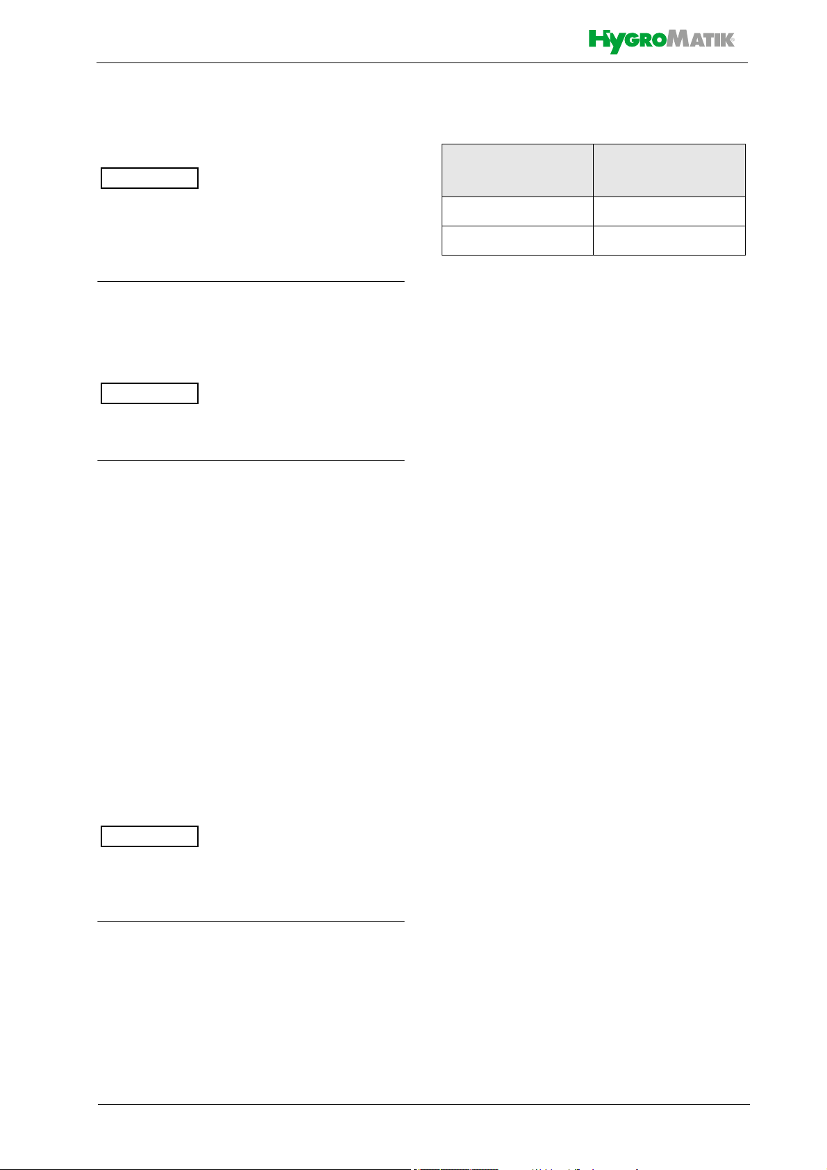
Time limits for filing freight claims with shipping companies are*:
Shipping company
Carriers no later than 4 days
Parcel service immediately
* Time limits for some services subject to
change.
After receipt of
goods
3.3 Interim Storage
Store the unit in a dry place and protect from
frost and strong sunlight.
3.4 Check for Complete and Correct Delivery of Goods
Upon receipt of the unit, confirm that:
• model and serial number on the
name plate match those specified in
the order and delivery documents
• the equipment is complete and all
parts are in perfect condition
In case of damage from shipment and/or
missing parts, immediately notify the carrier
or supplier in writing.
Page 9
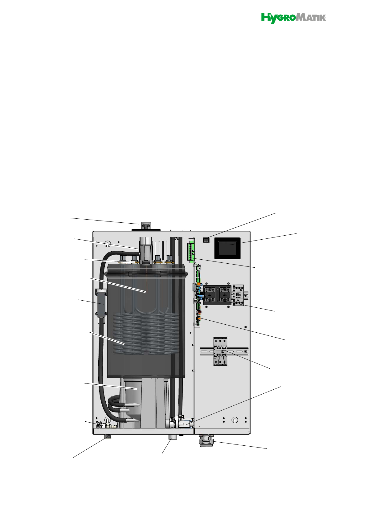
Control switch
Display
Main contactor
Blow-down
pump
Cable bushings
Waste water
outlet
Mainboard
(control)
Connector for heater
element wiring
Solid state relay
on heatsink
Water inlet
Solenoid valve
Cylinder base
Heater elements
Steam cylinder
Steam hose
adapter
Steam exit
Thermo switch
Level control
4. Functional Description and Device Composition
4.1 Mode of Action
The immersion heater principle
Depending on the output rating, one, three or
six heater elements are arranged within a
closed cylinder. Examplary given, the figure
below shows the heater elements and other
main components of a heater element steam
generator of the FLP series with 6 heater elements.
The cylinder(s) are filled with either tap water
of varying quality, fully desalinated water or
partially softened water.
The heat introduced by the heater elements
heats up the cylinderwater to approx. 100 °C
(212 °F), transforming the water into steam
with a temperature of approx. 100 °C (212 °F)
This steam is virtually mineral-free and germfree.
When fully desalinated water is used, the cylinder water is almost totally clear of minerals.
This situation guarantees a long lifetime of the
cylinder(s) and the heater element(s), since
virtually no hardeners will fall-out and no mineral deposits will occur. Such, the number of
inspections and/or maintenance operations
required will be reduced to a minimum.
When tap water is used for operation, some of
the minerals dissolved in the water are likely to
settle in the cylinder in form of solids of various
compositions. However, most of the solids are
flushed out by cyclic blow-down with the help
of a heavy-duty blow-down pump.
Page 10

4.2 Operational sequence
The steam humidifier is switched on by
pressing the control switch on the front panel
to the „I“ position. If the safety chain is
closed, the inlet multiple solenoid valve (twin
solenoid valve (25)
*)
in case of FLPxx-T and
FLPxx-TSPA units, 4-fold solenoid valve
*)
(71)
with FLPxx-TPRO units)* opens and
water is fed into the steam cylinder.
Filling level in the cylinder is controlled by a
level control device (27)
*)
. In a plastic cylinder, connected to the steam cylinder via
hoses in the way communicating tubes are
connected, a sensor for continous proportional water level survey is located.
The cylinder water is periodically blown
down. For usage of the unit with fully deselinated water, the blow-down function may be
blocked.
Water blow-down is achieved by means of
*)
the blow-down pump (32)
that is continously
monitored during unit operation. In case of
pump disruption, the HygroMatik steam
humidifier is shut off.
With normal water quality, blow-down loss is
in the range of 7 to 15% of the steam amount
produced. Depending on water quality, a full
steam cylinder blow-down is run every 3 to 8
days.
Mineral deposits settle in the open area
below the heater element(s) and are
removed through periodic maintenance. The
blow-down pump itself has wide openings
and can flush out smaller pieces of mineral
deposit. This extends the service life of the
unit and reduces the required maintenance
interval.
On blow-down, water flows from the pump
into the drain hose system.
4.3 Internal Output Setting
Continuous control is achieved by proportional driving (pulse width modulation) of the
heater elements via one or both solid state
relays. In this way the humidifier can be proportionally operated across the entire output
range of 5% - 100% of the nominal capacity.
A power setting of 0% to 5% of the nominal
output is possible, but not technically feasible
due to condensate losses in the steam line.
If the unit is equipped with more than 3
heater elements, the output power provision
is accomplished in 2 stages. As long as a
certain threshold was not reached, the heating power necessary is solely controlled via
the solid state relays and the 3 heater elements in a propotional manner (stage 1). If
the output power requested lies beyond what
is available in stage 1, three additional heater
elements are activated via a main contactor
in a one-step operation mode (stage 2). Any
power requirement in excess of the stage 2
rating is then proportionally supplied via the
solid state relays by the stage 1 operational
mode.
4.4 Mechanical Construction
The type of housing is designed for wall
mounting. The steam cylinder is made from
stainless steel. Depending on the power output range, one, three or six heater elements
are encorporated.
4.4.1 FlexLine Plus
Freshwater supply is accomplished by
means of a twin solenoid valve that is also
used for the SuperFlush functionality.
For maintainence purposes, the cylinder
4.4.2 FlexLine Process
water may be pumped out by pressing and
holding the control switch in the „II“ position.
The units featuring the TPRO-control allow
the exceedingly precise steam control via a
fourfold solenoid valve. For this to work, the
*)
numbers indicated correspond with those in
the exploded view in the „Exploded view“
use of fully demineralized water is mandatory.
chapter.
Page 11

4.5 Thermal fuses
The devices of the FLP series have several
thermal fuses which are electrically connected in series. After one of the fuses has
tripped, the device switches to the fault status. A device restart is required but is possible only if the relevant thermal switches have
cooled down or the thermal sensors have
been unlocked.
The following fuses are available:
on the cylinder cover
• 1 thermal switch (Klixon) to protect
against overheating of the steam cylinder; the switch has a pin for manual
reset after cooling down
• 1 or 2 (for devices with six radiators)
thermal sensors with capillary tube for
direct thermal monitoring of the radiators. One capillary tube each is connected to 1 to 3 radiators (depending
on the device type). After a thermal
sensor has been triggered, it must be
reset manually (see maintenance
description)
on solid state relays
The solid state relay (or two solid state relays
on devices with higher power) is (are) thermally protected by a bimetal switch. The
bimetal switch returns to its initial position
during the cooling process.
Page 12

:$51,1*
:$51,1*
5. Mechanical installation
Risk of foot injuries!
Prevent unit from dropping during installation!
Helping hand of a second person is advisable.
Risk of electrical shock!
Hazardous electrical voltage.
During installation, the unit must be disconnected from power supply.
5.1 Environment Parameters to
be met and Mounting Recommendations
When selecting the installation site for the
steam humidifier, take the following into
account:
• The minimum clearances indicated in
the fitting measures section must be
observed in order to ensure adequate
unit ventilation and allow for unobstructed access in case of maintenance
• Protection class IP20
• Installation in a closed room requires
aeration and, eventually, temperature
conditioning in order to meet the a.m.
environmental conditions
• The steam humidifier should be
installed as close as possible to the
steam manifold. Optimum performance is only guaranteed when steam
and condensate hoses are kept short
• Make use of existing water connections
for supply and draining
• Hoses must be laid at a consistent 5 to
10 % incline/decline; sagging and kinking prevention is a must
• Mount the unit on a stable, preferably
solid wall offering the bearing capacity
required (s. unit technical specifications). If such a wall is not at hand, the
unit may be attached to a stand bracket
firmly bolted to the floor
• For proper functioning of the level control, plumb and level installation of the
unit is required
• The steam humidifier rear panel heats
up during operation to a maximum of
70 °C (158 °F). Take care that the construction on which the unit is to be
mounted is not made of temperaturesensitive material
• By design, HygroMatik steam humidifiers are not qualified for outdoor installation (electronical components and
water-bearing parts may be damaged)
• Ambient temperature must lie between
+5 and +40 °C (+41 and +104 °F) in
order to protect the unit electronics
against damage; frost may damage the
steam cylinder, the solenoid valve and
pump, as well as make hoses burst
• Relative humidity must not exceed
80 % r.h., since values beyond may
lead to electronic malfunction or damage
Page 12
PP
LQFK
PP
LQFK
PP
LQFK
PP
LQFK
PP
LQFK
PP
LQFK
PP
LQFK
PP
LQFK
PP
LQFK
PP
LQFK
PP
LQFK
PP
LQFK
PP
LQFK
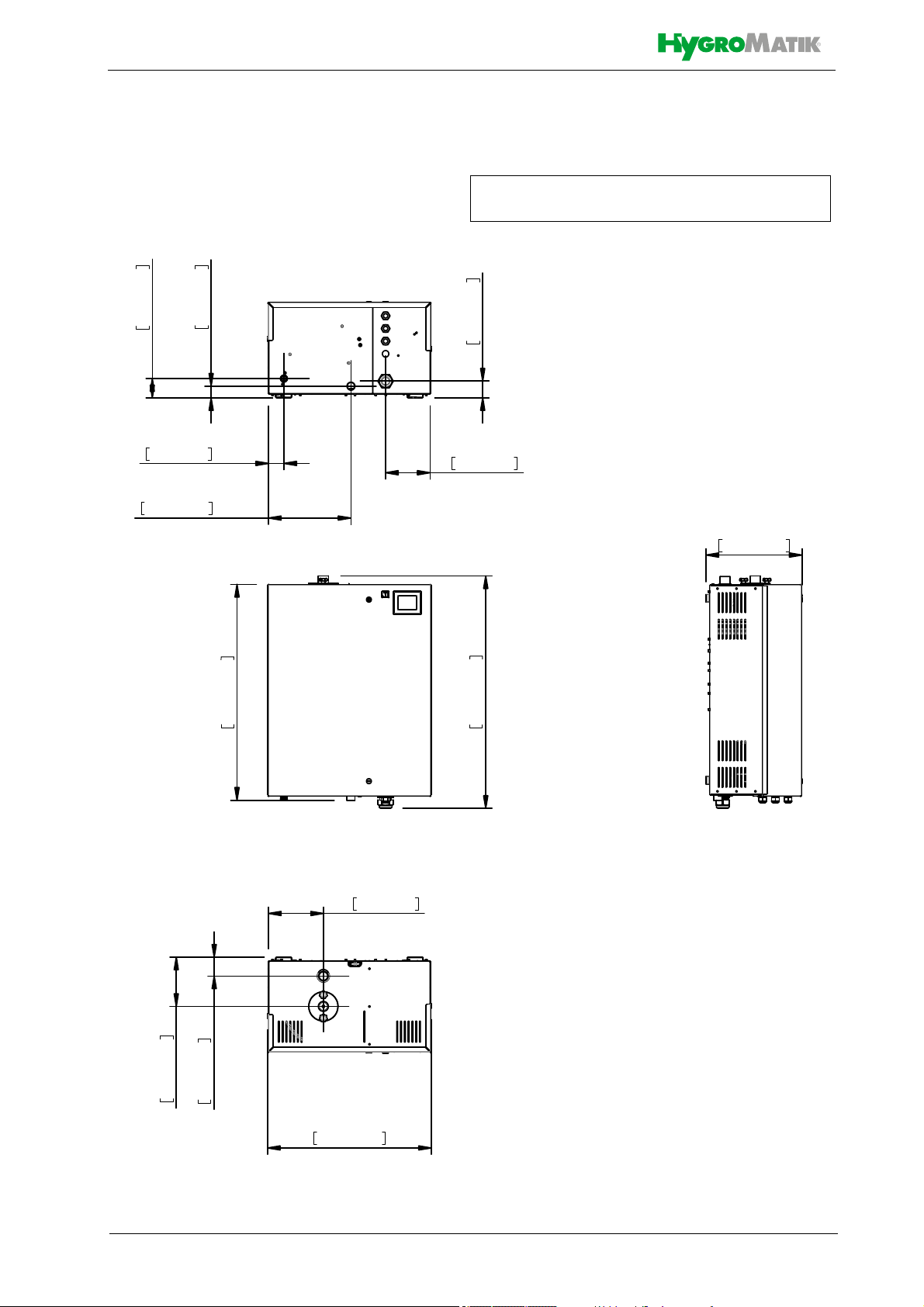
View from below
View from top
Front view
3D model under
https://www.hygromatik.com/en/downloads
5.1.1 Dimensions and Mounting Directions
Page 14
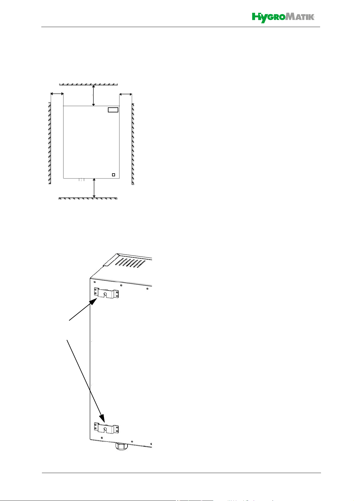
>500/19.7
>200/7.8
>300/11.8
>50/2.0
device rear
suspension
brackets
Wall clearances
When mounting the steam humidifier, the
wall clearances shown in the fig. below must
be obeyed:
all measures in mm/inch
For wall mounting drill measures, please
consult the table above (measure A and B).
In case of no suitable wall available for
mounting the unit, it is recommended that
installation is made on brackets firmly
anchored in the floor.
» mark the holes for the upper sus-
pension brackets
screws
» drill holes and dowel
» screw in the supplied mounting
screws; let the screws protrude
approx. 12 mm
/.5 inch from wall
» ensure firm fixation and load-carry-
ing capacity of the mounted screws!
» hook in the unit and ensure safe
suspension
» mark the holes for the lower suspen-
sion brackets screws
» remove the unit
» drill holes and dowel
» hook in the unit and mount the lower
screws firmly
To function properly, the steam humidifier
must hang level and plumb.
Mounting principle
Page 15
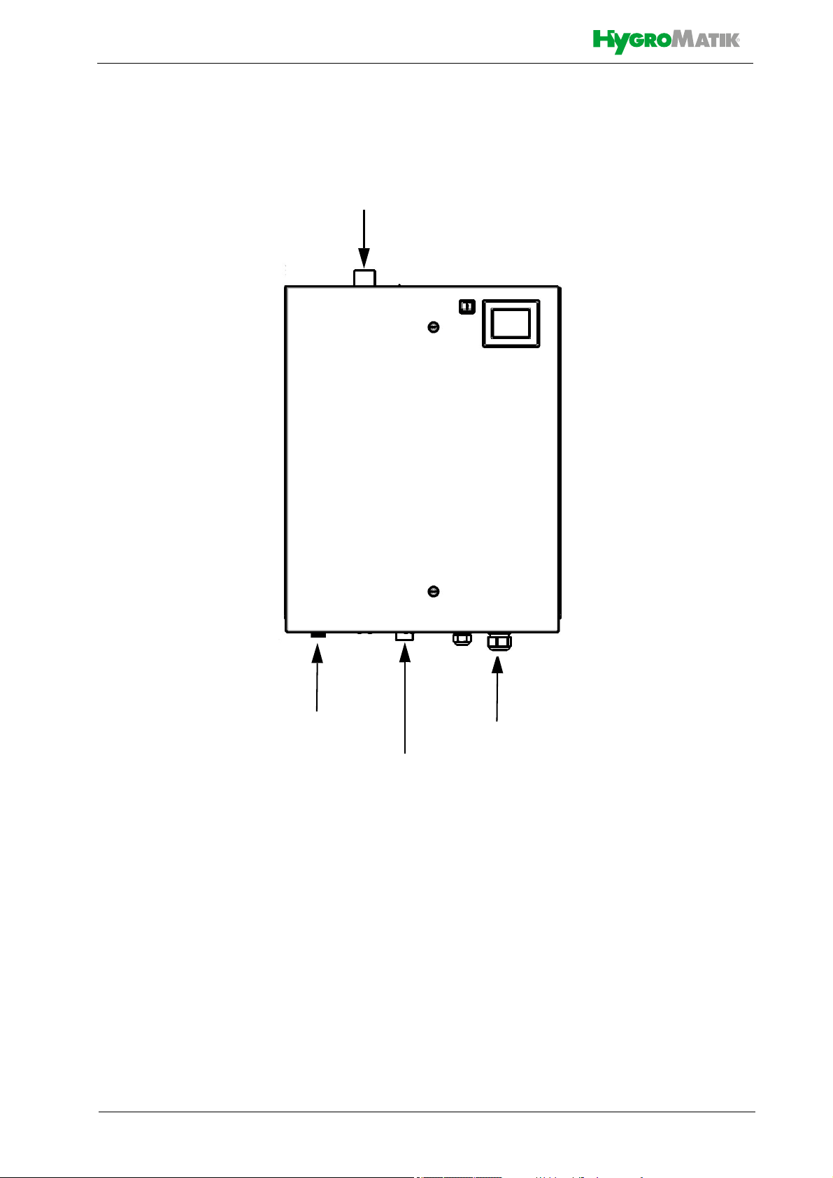
Cable entries
1¼“ Waste water connection
¾“ Water inlet
DN25, DN40 Steam outlet
Device connections:
Page 16

5.2 Unit Installation Check
Before start-up, pls. check proper unit installation following the list below:
Unit perpendicularly aligned in both
the vertical and horizontal axis ?
All clearances obeyed?
Steam hose installed with a 5 - 10 %
minimum incline/decline (see chapter "Steam line“) ?
Condensate hose features a loop
functioning as a steam barrier (see
chapter „Condensate hose“) ?
Steam manifold(s) properly positio-
ned?
All bolts and clamps properly tighte-
ned?
Steam manifold(s) horizontally mon-
ted and suspended on the free end,
if required ?
All seals (o-rings) in place?
All ventilation slots on housing top
unobscured?
Page 16
 Loading...