

HygroMatik FLE25, FLE15, FLE10, FLE20, FLE40 User Manual
...
FlexLine
Electrode Steam Humidifiers
ÁFLE.CSAoÈ
FLE.CSA
E-8881762
IMPORTANT: READ AND SAVE THESE INSTRUCTIONS
Manual

Page 2
Risk of electrical shock!
Hazardous electrical high voltage!
All electrical work to be performed by certified expert staff (electricians or expert personnel with
eqivalent training) only.
Certain computer programs contained in this product [or device] were developed by HygroMatik
GmbH ("the Work(s)").
Copyright © HygroMatik GmbH [07.05.2018]
FLE 05/10/15/20/25/30/40/50/65/80/100/130 CSA
All Rights reserved.
Current version of this manual can be found at: www.hygromatik.co.uk
HygroMatik GmbH grants the legal user of this product [or device] the right to use the Work(s)
solely within the scope of the legitimate operation of the product [or device]. No other right is
granted under this licence. In particular and without prejudice to the generality of the foregoing,
the Work(s) may not be used, sold, licensed, transferred, copied or reproduced in whole or in
part or in any manner or form other than as expressly granted here without the prior written consent of HygroMatik GmbH.
Information in this manual is subject to change or alteration without prior notice.
:$51,1*

Page 3
1. Introduction ....................................................................................................................... 5
1.1 Typographic Distinctions ...................................................................................................5
1.2 Documentation .................................................................................................................. 5
1.3 Symbols in Use ................................................................................................................. 5
1.3.1 Specific Symbols related to Safety Instructions .............................................................5
1.3.2 General Symbols ............................................................................................................5
1.4 Intended Use .....................................................................................................................6
2. Safety Instructions ............................................................................................................7
2.1 Guidelines for Safe Operation ........................................................................................... 7
2.1.1 Scope ............................................................................................................................. 7
2.1.2 Unit control ..................................................................................................................... 7
2.1.3 Unit Operation ................................................................................................................7
2.1.4 Mounting, dismantling, maintenance and repair of the unit ............................................ 8
2.1.5 Electrical .........................................................................................................................8
2.2 Disposal after dismantling ................................................................................................8
3. Transport ............................................................................................................................ 9
3.1 Overview ...........................................................................................................................9
3.2 Packing ..............................................................................................................................9
3.3 Interim Storage ..................................................................................................................9
3.4 Check for Complete and Correct Delivery of Goods .........................................................9
4. Functional Description and Device Composition .......................................................... 10
4.1 Mode of Action .................................................................................................................. 10
4.2 Mechanical Construction ...................................................................................................10
4.3 Operating sequence ..........................................................................................................11
5. Mechanical installation .....................................................................................................12
5.1 Environment Parameters to be met and Mounting Recommendations ............................. 12
5.1.1 Dimensions and Mounting Directions .............................................................................13
5.2 Unit Installation Check ....................................................................................................... 16
5.3 Absorption Distance BN ....................................................................................................17
5.3.1 Determining the Absorption Distance ............................................................................. 17
5.3.2 Absorption Distance Nomogram .................................................................................... 18
5.4 Steam Manifold .................................................................................................................19
5.4.1 General installation guidelines .......................................................................................19
5.4.2 Recommendations for dimensioning .............................................................................. 19
5.5 Steam line and condensate hose layout .......................................................................... 22
5.5.1 Guide lines for steam line design ..................................................................................22
5.5.2 Condensate hose layout ................................................................................................. 22
5.5.3 Steam line and condensate hose installation types .......................................................23
6. Water connection ..............................................................................................................24
6.1 Operation with softened water ...........................................................................................24
6.2 Water supply .....................................................................................................................25
6.3 Water discharge ................................................................................................................ 25
6.4 Water connections final check ...........................................................................................26

Page 4
7. Electrical connection ........................................................................................................27
7.1 Electrical installation approach ..........................................................................................27
7.2 Cable connections .............................................................................................................28
7.3 Connection of interlock (safety) system ............................................................................ 29
7.4 Full wiring diagrams .......................................................................................................... 29
7.5 Electrical installation check list .......................................................................................... 29
8. Commissioning ................................................................................................................. 30
9. Maintenance ....................................................................................................................... 31
9.1 General ..............................................................................................................................31
9.1.1 Service messages ..........................................................................................................31
9.1.2 Service messages for preventive maintenance .............................................................. 31
9.1.3 Safety instructions for maintenance ............................................................................... 32
9.2 Maintenance frame work ................................................................................................... 33
9.3 Removal and reinstallation of the steam cylinder .............................................................. 34
9.4 Steam cylinder, electrodes and cylinder base cleaning .................................................... 38
9.5 Checking cable connections .............................................................................................. 38
9.6 Solenoid valve removal/reinstallation and fine filter cleaning ............................................ 39
9.7 Cleaning of blow-down pump ............................................................................................ 40
9.8 Inspection of hoses ...........................................................................................................41
9.9 Electrode replacement ......................................................................................................41
9.10 Functional check .............................................................................................................42
9.11 Finishing maintenance .................................................................................................... 42
10. Dismantling ......................................................................................................................43
11. CSA Certificate of Compliance ......................................................................................44
12. Spare Parts ...................................................................................................................... 47
13. Technical specifications ................................................................................................. 50
14. Exploded view ................................................................................................................. 52
15. View of housing ............................................................................................................... 53

Page 5
1. Introduction
Dear Customer,
Thank you for choosing a HygroMatik steam
humidifier.
HygroMatik steam humidifiers represent the
latest in humidification technology.
In order to operate your HygroMatik steam
humidifier safely, properly and efficiently,
please read these operating instructions.
Employ your steam humidifier only in sound
condition and as directed. Consider potential
hazards and safety issues and follow all the
recommendations in these instructions.
If you have additional questions, please contact your expert dealer.
For all technical questions or spare parts
orders, please be prepared to provide unit
type and serial number (see name plate on
the unit).
1.1 Typographic Distinctions
• Preceded by a bullet: general specifications
» Preceded by an arrow: procedures
for servicing or maintenance which
should or must be performed in the
indicated order
Installation step which must be
checked off.
italics Terms used with graphics or
drawings
1.2 Documentation
Retention
Please retain these operating instructions in
a secure, always accessible location. If the
product is resold, turn the documentation
over to the new operator. If the documentation is lost, please contact HygroMatik.
Versions in Other Languages
These operating instructions are available in
several languages. If interested, please contact HygroMatik or your HygroMatik dealer.
1.3 Symbols in Use
1.3.1 Specific Symbols related to
Safety Instructions
According to ANSI Z535.6 the following
signal words are used within this document:
DANGER indicates a hazardous situation
which, if not avoided, will result in death or
serious injury.
WARNING indicates a hazardous situation
which, if not avoided, could result in death or
serious injury.
CAUTION indicates a hazardous situation
which, if not avoided, could result in minor or
moderate injury.
NOTICE is used to address practices not
related to physical injury.
1.3.2 General Symbols
This symbol is used whenever a situation
requires special attention beyond the scope
of safety instructions.
'$1*(5
:$51,1*
&$87,21
127,&(127,&(
3OHDVHQRWH
Page 6
1.4 Intended Use
HygroMatik electrode steam humidifiers
serve for steam production based on tap
water or partially softened water.
Only use supply water featuring a conductivity of 125 to 1250 µS/cm.
D1: Lower threshold
C1: Range of reduced conductivity
(adjustment required)
A: Normal Tap water
B: Range of increased conductivity
C2: Range of high conductivity
(adjustment required)
D2: Upper threshold
In the C1 and C2 ranges, adaptation of the
periodic blow-down frequency may be
required. Pls. refer to the partial and full blowdown parameter descriptions given in the
blow-down submenu chapter as well as in the
glossary.
Proper usage also comprises the adherence
to the conditions specified by HygroMatik for:
• installation
• dismantling
• reassembly
• commissioning
• operation
• maintenance
• disposal
Only qualified and authorised personnel may
operate the unit. Persons transporting or
working on the unit must have read and
understood the respective parts of this manual, especially the „Safety Instructions“ given
in chapter 2. Additionally, operating personnel must be informed of any possible hazards. A copy of the manual is to be stored at
the unit‘s operational location (or near the
unit).
By construction, HygroMatik steam humidifiers are not qualified for exterior application.
Risk of scalding!
Steam with a temperature of up to 100 °C
(212 °F) is produced.
Do not inhalate steam directly!
:$51,1*
Page 7
2. Safety Instructions
These safety instructions are required by law.
They promote workplace safety and accident
prevention.
2.1 Guidelines for Safe Operation
2.1.1 Scope
Comply with the accident prevention regulation „DGUV Regulation 3“ to prevent injury to
yourself and others. Beyond that, national
regulations apply without restrictions.
2.1.2 Unit control
Do not perform any work which compromises
the safety of the unit. Obey all safety instructions and warnings present on the unit.
In case of a malfunction or electrical power
disruption, switch off the unit immediately and
prevent a restart. Repair malfunctions
promptly.
Restricted use.
IEC 60335-1 stipulates as follows:
This device may be used by children of eight
years of age and above as well as by persons
with reduced physical, sensory or mental capabilities or lack of experience and knowledge
so long as they are supervised or have been
instructed regarding the safe use of the device and understand the hazards that may result from it. Cleaning and user maintenance of
the unit must not be undertaken by children
without supervision.
2.1.3 Unit Operation
Risk of scalding!
Uncontrolled hot steam escape in case of
leaking or defective components possible.
Switch off unit immediately.
Risk of material damage!
The unit may be damaged if switched on
repeatedly following a malfunction without
prior repair.
Rectify defects immediately!
The unit must not be operated on a DC
power supply.
The unit may only be used connected to a
steam pipe that safely transports the steam.
Regularly check that all safety and monitoring devices are functioning normally. Do not
remove or disable safety devices.
:$51,1*
:$51,1*
127,&(127,&(
Page 8
2.1.4 Mounting, dismantling, maintenance and repair of the unit
The HygroMatik steam humidifier is IP20 protected. Make sure that the unit is not object to
dripping water in the mounting location.
Installing a humidifier in a room without water
discharge requires safety devices to protect
against water leakages.
• Use genuine spare parts only
• After any repair work, have qualified
personnel check the safe operation of
the unit
• Attaching or installing of additional
components is permitted only with the
written consent of the manufacturer
2.1.5 Electrical
Risk of electrical shock!
Hazardous electrical voltage!
Any work on the electrical system to be per-
formed by certified expert staff (electricians
or expert personnel with comparable training)
only.
Disconnect unit components from electrical
power supply prior to work.
After electrical installation or repair work, test
all safety mechanisms (such as grounding
resistance).
Use only original fuses with the appropriate
amperage rating.
Regularly check the unit‘s electrical equipment. Promptly repair any damage such as
loose connections or burned wiring.
Responsibility for intrinsically safe installation
of the HygroMatik steam humidifiers is
incumbent on the installing specialist company.
2.2 Disposal after dismantling
The operator is responsible for the disposal
of unit components as required by law.
127,&(127,&(
:$51,1*
127,&(127,&(
127,&(127,&(
Page 9
3. Transport
3.1 Overview
Proceed carefully when transporting the
steam humidifier in order to prevent damage
due to stress or careless loading and unloading.
3.2 Packing
Pay attention to the icons affixed to the packing box.
3.3 Interim Storage
Store the unit in a dry place and protect from
frost and strong sunlight.
3.4 Check for Complete and Correct Delivery of Goods
Upon receipt of the unit, confirm that:
• model and serial number on the
name plate match those specified in
the order and delivery documents
• the equipment is complete and all
parts are in perfect condition
In case of damage from shipment and/or
missing parts, immediately notify the carrier
or supplier in writing.
Time limits for filing freight claims with shipping companies are*:
* Time limits for some services subject to
change.
3OHDVHQRWH
3OHDVHQRWH
3OHDVHQRWH
Shipping company
After receipt of
goods
Carriers no later than 4 days
Parcel service immediately
Page 10
4. Functional Description and
Device Composition
4.1 Mode of Action
Making use of the frictional heat caused
by current flow in a water tank
The HygroMatik humidifier utilizes the conductivity normally present in tap water for
steam production. Electrodes inside an
enclosed steam cylinder are immersed
directly into the tap water. They are connected to the alternating current.
The conductivity of the water generates an
electric current between the electrodes. In
this way, the electric power supplied is converted directly into heat without energy loss.
The steam produced has a temperature of
about 100°C (212°F) with minimal excess
pressure ("pressureless steam"). It is largely
free of minerals and germ-free. Mineral
deposits typically remain behind in the cylinder.
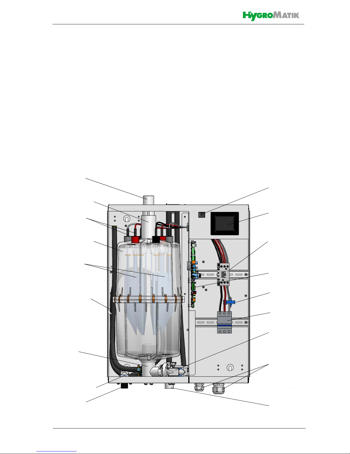
4.2 Mechanical Construction
The FlexLine humidifiers are designed for
wall mounting.
Steam cylinder
Steam exit
Manual drain
hose
Solenoid valve
Water inlet
Blow-down
pump
Cicuit
breaker
Current transducer
Mainboard
(Control)
Main contactor
Display
Control switch
Cable
bushings
Waste water
outlet
Cylinder
base
Electrode
plugs
Steam adapter
Electrodes

Page 11
4.3 Operating sequence
By pressing the control switch („Pos. I”) the
humidifier is turned on. When the controller
specifies an increase in humidity, the main
contactor is switched on and the electrodes
(48)
*)
are supplied with power. The water inlet
solenoid valve (25)
*)
feeds water into the
steam cylinder (16)
*)
.
As soon as the electrodes are immersed, the
current begins to flow. The water is now
heated. When the pre-selected output is
reached, the control turns off the solenoid
valve and interrupts the water supply.
After a short heating up period, the water
between the electrodes begins to boil and
vaporize. The vaporization lowers the water
level in the steam cylinder, reducing the output provided. The inlet solenoid valve,
equipped with a fine mesh filter, intermittently
admits fresh water.
Humidifier power usage is continuously monitored. With a cold start-up, the nominal current increases to 113% in order to achieve
quick-start output parameters. This activates
the electronic overflow limiter which causes a
partial draining of the cylinder. This reduces
the immersed surface area of the electrodes,
lowering power usage.
The concentration of dissolved salts
increases over time, which can lead to a rise
in the conductivity of the water. If this continues, conductivity may increase until a short
circuit occurs. This could damage the unit,
but in any case would significantly reduce the
life span of the electrodes.
For this reason, regular, periodic blow-downs
of some of the concentrated water are very
important. Following this procedure as recommended provides stable cylinder water
conductivity as well as minimal water loss for
the expected service life of the cylinder.
Water blow-down is performed by a blowdown pump 32)
*)
. The functioning of the
blow-down pump is continuously monitored
during operation. If the pump is damaged, the
steam humidifier shuts down.
With normal water quality the blow-down loss
rate lies between 7 and 15 % of the amount
of steam produced. Depending on water
quality, a full steam cylinder blow-down is run
every 3 to 8 days.
Mineral deposits settle in the open area
below the electrodes and are removed
through periodic maintenance. The blowdown pump itself has wide openings and can
flush out smaller pieces of mineral deposit.
This extends the service life of the unit and
reduces the required maintenance interval.
On blow-down, water flows from the pump
into the drainage system.
For maintainence purposes, the cylinder
water may be pumped out by pressing and
holding the control switch in the „II“ position.
Monitoring max. level
A sensor electrode (10)*) monitors the maxi-
mum water capacity of the cylinder. When the
water level reaches the sensor electrode, the
water supply is interrupted. This can occur
when the water has low conductivity or when
the electrodes are worn out. In the case of
low water conductivity, however, this state
usually lasts only a short time. The built-in
control and the large area electrodes combine to produce a rapid rise in conductivity by
increasing the concentration of the water.
*)
numbers indicated correspond with those
in the exploded view in the „Exploded view“
chapter.
Page 12
5. Mechanical installation
Risk of foot injuries!
Prevent unit from dropping during installation!
Helping hand of a second person is advisable.
Risk of electrical shock!
Hazardous electrical voltage.
During installation, the unit must be disconnected from power supply.
5.1 Environment Parameters to
be met and Mounting Recommendations
When selecting the installation site for the
steam humidifier, take the following into
account:
• The minimum clearances indicated in
the fitting measures section must be
observed in order to ensure adequate
unit ventilation and allow for unobstructed access in case of maintenance
• Protection class IP20
• By design, HygroMatik steam humidi-
fiers are not qualified for outdoor installation (electronical components and
water-bearing parts may be damaged)
• Ambient temperature must lie between
+5 and +40 °C (+41 and +104 °F) in
order to protect the unit electronics
against damage; frost may damage the
steam cylinder, the solenoid valve and
pump, as well as make hoses burst
• Relative humidity must not exceed
80 % r.h., since values beyond may
lead to electronic malfunction or damage
• Installation in a closed room requires
aeration and, eventually, temperature
conditioning in order to meet the a.m.
environmental conditions
• The steam humidifier should be
installed as close as possible to the
steam manifold. Optimum performance is only guaranteed when steam
and condensate hoses are kept short
• Make use of existing water connections
for supply and draining
• Hoses must be laid at a consistent 5 to
10 % incline/decline; sagging and kinking prevention is a must
• Mount the unit on a stable, preferably
solid wall offering the bearing capacity
required (s. unit technical specifications). If such a wall is not at hand, the
unit may be attached to a stand bracket
firmly bolted to the floor
• For proper functioning of the level control, plumb and level installation of the
unit is required
• The steam humidifier rear panel heats
up during operation to a maximum of
70 °C (158 °F). Take care that the construction on which the unit is to be
mounted is not made of temperaturesensitive material
:$51,1*
:$51,1*
Page 13
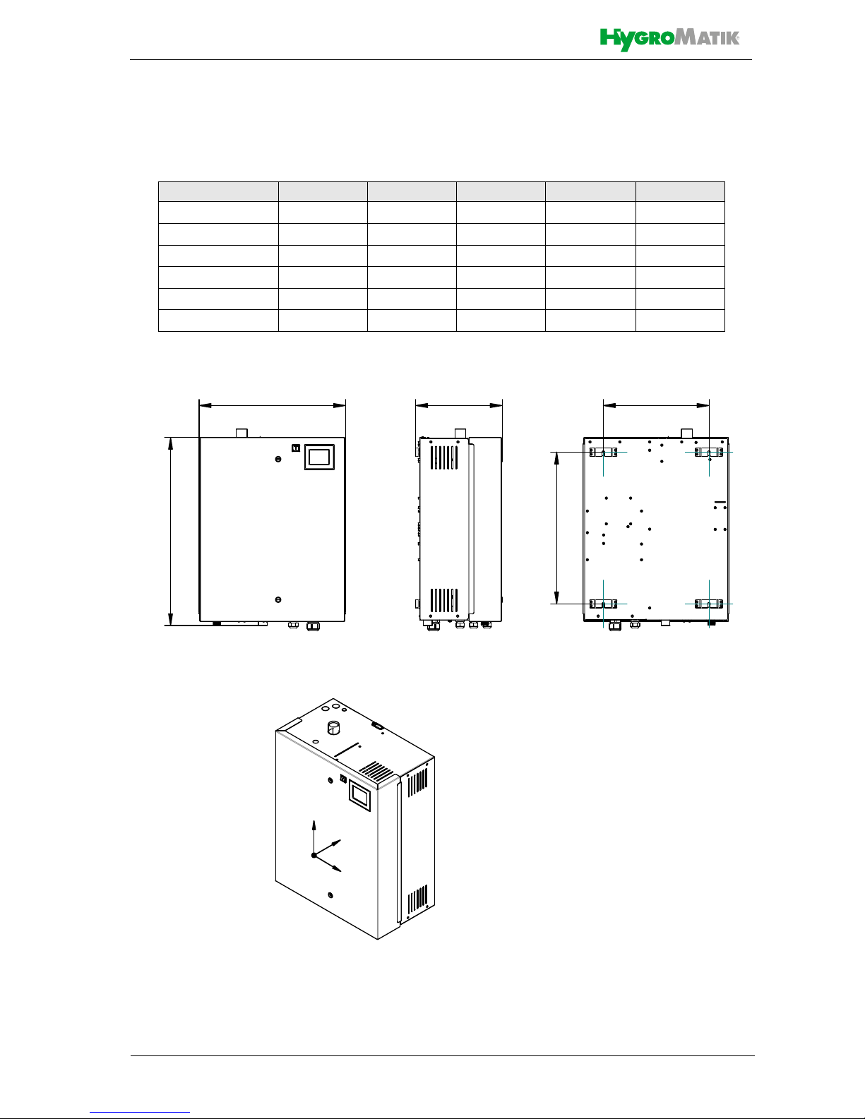
5.1.1 Dimensions and Mounting
Directions
Table of dimensions
Model X [mm/inch] Y [mm/inch] Z [mm/inch] A [mm/inch] B[mm/inch]
FLE05-FLE10 540/~21.3 535/~21 320/~12.6 390/~15.4 400/~15.7
FLE15-FLE25 540/~21.3 695/~27.4 320/~12.6 390/~15.4 560/~22
FLE30-FLE40 580/~22.8 750/~29.5 355/~14 425/~16.7 620/~24.4
FLE50-FLE65 640/~25 785/~30.9 420/~16.5 490/~19.3 650/~25.6
FLE80 1090/~43.1 750/~29.5 355/~14 870/~34,4 620/~24.4
FLE100-FLE130 1170/~46 785/~30.9 420/~16.5 1000/~39.4 660/~25.6
Z
X
Y
<
=; $
%
Page 14
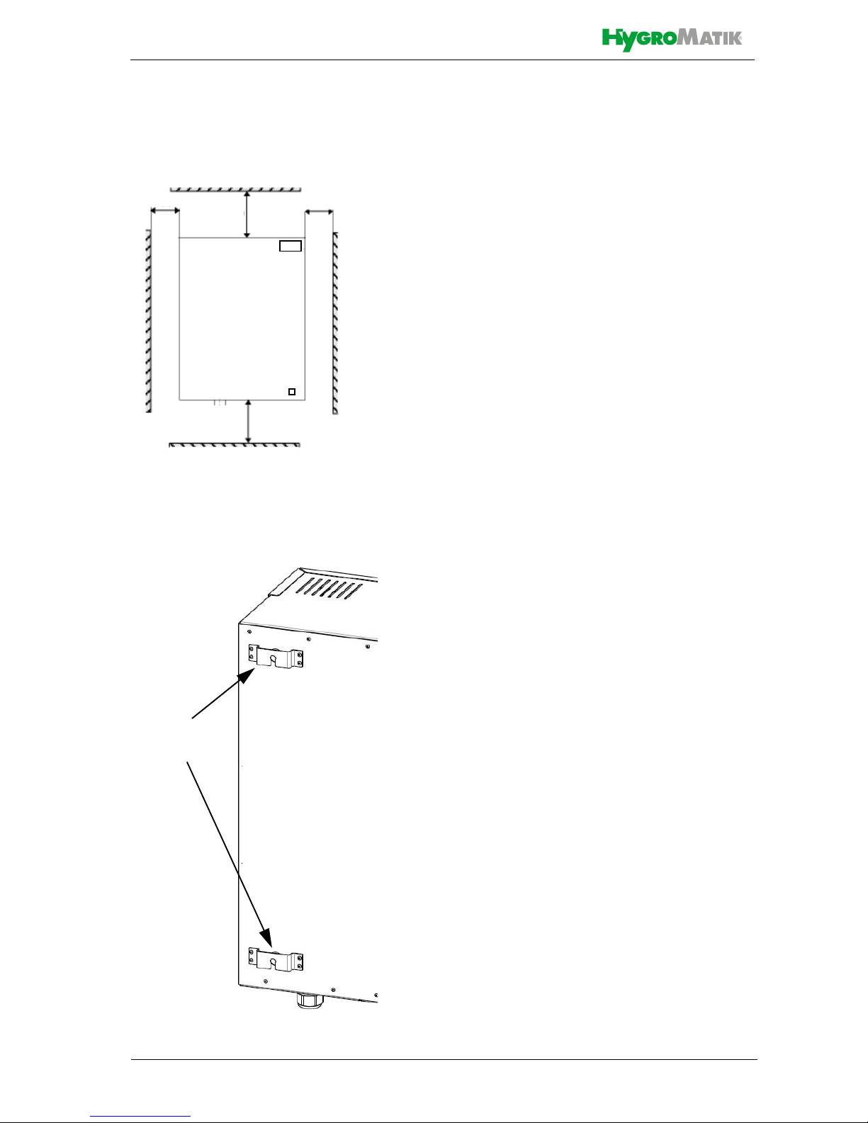
Wall clearances
When mounting the steam humidifier, the
wall clearances shown in the fig. below must
be obeyed:
Mounting principle
For wall mounting drill measures, please
consult the table above (measure A). In case
of no suitable wall available for mounting the
unit, it is recommended that installation is
made on brackets firmly anchored in the
floor.
» mark the holes for the upper sus-
pension brackets
screws
» drill holes and dowel
» screw in the supplied mounting
screws; let the screws protrude
approx. 12 mm
/.5 inch from wall
» ensure firm fixation and load-carry-
ing capacity of the mounted screws!
» hook in the unit and ensure safe
suspension
» mark the holes for the lower suspen-
sion brackets screws
» remove the unit
» drill holes and dowel
» hook in the unit and mount the lower
screws firmly
To function properly, the steam humidifier
must hang level and plumb.
>500/19.7
>200/7.8
>300/11.8
>50/2.0
device rear
suspension
brackets
all measures in mm/inch
Page 15
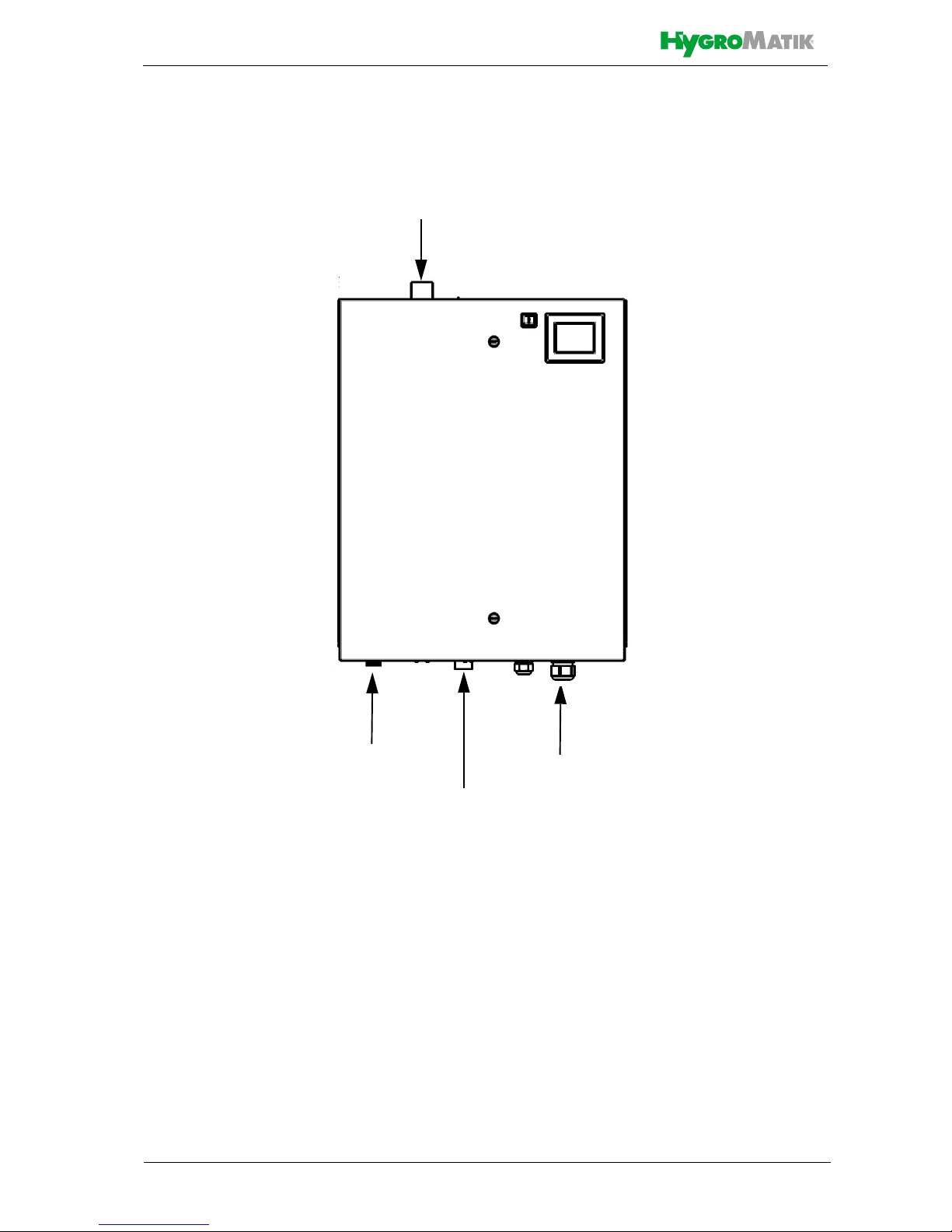
Device connections:
Cable entries
1¼“ Waste water connection
¾“ Water inlet
DN25, DN40 Steam outlet

Page 16
5.2 Unit Installation Check
Before start-up, pls. check proper unit installation following the list below:
Unit perpendicularly aligned in both
the vertical and horizontal axis ?
All clearances obeyed?
Steam hose installed wit h a 5 - 10 %
minimum incline/decline (see chapter "Steam line“) ?
Condensate hose features a loop
functioning as a steam barrier (see
chapter „Condensate hose“) ?
Steam manifold(s) properly positio-
ned?
All bolts and clamps properly tighte-
ned?
Steam manifold(s) horizontally mon-
ted and suspended on the free end,
if required ?
All seals (o-rings) in place?
All ventilation slots on housing top
unobscured?
Page 17
5.3 Absorption Distance BN
The "absorption distance" (BN) is defined as
the distance from the steam feed to where
the steam is completely absorbed in the
treated air. Within the absorption distance,
steam is visible as mist in the air stream.
Condensation may occur on anything
installed within the absorption distance.
Although steam outside the absorption distance (B
N
) is completely absorbed, it is not
yet evenly diffused in the duct. If you plan to
install any parts or devices inside the absorption distance, such as sensors or elbows, we
recommend increasing the absorption distance using the formulae below. The absorption distances required for certain installed
fittings are distinguished by separate symbols and calculated as a multiplier of the
absorption distance B
N
.
The absorption distance has no fixed value,
but depends on many factors. These are
depicted in the absorption distance nomogram below.
5.3.1 Determining the Absorption
Distance
To determine the absorption distance, the following parameters are required:
• Air humidity before humidification x
1
in g/kg
• Air temperature after humidification
t
2
in °C (with steam humidifiers the
change in air temperature due to
humidification may be disregarded
t
1
or t2)
• Specific increase in humidity x in
g/kg (can be determined in the h,x
diagram)
• quantity of steam introduced in
kg/h.
• air speed w
L
in m/s in air duct
• Total length l
D
of the steam manifold
installed in the air duct
Length I
D
of the usable steam manifold
depends on the dimensions of the air duct.
The length of the absorption distance can be
reduced by using multiple steam manifolds
(also see section on the steam manifold).
Method:
Graphically determine absorption distance
B
N
using the absorption distance nomogram
(also see Section „Absorption Distance
Nomogramm“). Enter the value of the parameters enumerated above into the respective
quadrants. The resulting point of intersection
indicates the value of the desired absorption
distance B
N
.
Notes:
Air humidity before humidification x
1
:....[g/kg]
Air temperature after humidification t
2
:.....[°C]
Specific increase in humidity x:...........[g/kg]
Quantity of steam introduced :.........[kg/h]
Air speed W
L
:..........................................[m/s]
Total length of steam manifold l
D
:...........[mm]
o
D
m
o
D
m
Absorption Distance
B
N
for normal obstructions
such as sensors, ventilators, outlets
B
c
= (1.5...2) x BNfor fine fiters, heat regis-
ters
B
s
= (2.5...3) x BNfor particle filters
B
d
= (3...5) x BNfor humidity sensors,
duct humidistats
 Loading...