

Page 1
CompactLine KIT
Electrode Steam Humidifier
Manual
Page 2
Page 2
A Word about Water Quality
The mode of operation of all electrode steam humidifiers is based on the fact that water contains
minerals and is therefore conductive.
• "normal" tap water is ideal.
• but what is "normal" tap water exactly?
Users of HygroMatik units in the most diverse areas consider their tap water "normal."
HygroMatik typically defines "normal" as feed water with a conductivity between 200 and 500 µS/
cm (microSiemens per centimeter) at 15° C.
Some areas, however, are supplied with tap water whose quality is outside th e parameters specified by HygroMatik. If the HygroMatik steam humidifier's control is not adjusted correctly in these
areas, the unit cannot perform optimally. For example, the electrodes could wear out particularly
quickly or the steam production could be too low.
The operational parameters set by HygroMatik in the factory are intended for normal tap water.
However, they can very easily be reprogrammed to fit the special requirements of a particular
area. In addition, it is possible to install a plastic star in the cylinder in order to increase the life
span of the electrodes or to provide a flushing mechanism to extend maintenance intervals.
Because of this you should monitor your new unit during initial operation. Make sure that it has
been properly installed and is operating to your satisfaction.
Consult your HygroMatik specialists. We will test the quality of your water and advise you on
installation and initial operation. Your HygroMatik steam humidifier will be carefully adapted to
your particular application.
Warning, Hazardous Voltage: All work to be performed by trained personnel only.
All electrical installation and servicing of the electrical components of this unit to be
performed by qualified electricians only. Disconnect power supply before installation
and servicing!
© Copyright HygroMatik GmbH; CompactLine KIT, March 2013
Information in this manual is subject to change or alteration without prior notice.
Current version of this manual can be found at: www.hygromatik.co.u
k
Page 3

Page 3
1. Introduction ....................................................................................................................... 5
1.1 Directions for Use ..............................................................................................................5
1.2 Typographic Distinctions ...................................................................................................6
1.3 Documentation .................................................................................................................. 7
2. Safety Notes ....................................................................................................................... 8
2.1 Overview ........................................................................................................................... 8
2.2 Guidelines for Safe Operation ...........................................................................................8
2.3 Disposal after Dismantling .................................................................................................9
3. Transport ............................................................................................................................ 10
3.1 Overview ........................................................................................................................... 10
3.2 Carton outer Size and Weight ...........................................................................................10
3.3 Packing ..............................................................................................................................10
3.4 Interim Storage ..................................................................................................................10
3.5 Check for Complete and Correct Delivery of Goods .........................................................10
4. Operation and Installation ................................................................................................ 11
4.1 Mode of Operation .............................................................................................................11
4.2 Installation and Operation .................................................................................................11
5. Installation ......................................................................................................................... 14
5.1 Steam Humidifier Operating Environment ......................................................................... 14
5.1.1 Fitting ..............................................................................................................................15
5.1.2 Equipment Dimensions CompactLine KIT ......................................................................16
5.2 Fan Unit (optional) ............................................................................................................. 17
5.2.1 Fan Unit Type VG ...........................................................................................................17
5.3 Absorption Distance BN ....................................................................................................18
5.3.1 Determining the Absorption Distance ............................................................................. 18
5.3.2 Absorption Distance Nomogram .................................................................................... 20
5.4 Steam Manifold .................................................................................................................21
5.4.1 Notes on Installation ....................................................................................................... 21
5.5 Steam Line ........................................................................................................................ 25
5.6 Cover Plate ........................................................................................................................ 26
5.7 Drill Pattern ........................................................................................................................ 27
5.7.1 Drill Pattern DN25 (not to scale) .....................................................................................27
5.7.2 Drill Pattern DN40 (not to scale) .....................................................................................28
5.8 Condensate Hose .............................................................................................................. 29
5.9 Types of Installation ..........................................................................................................29
5.10 Steam Solenoid Valves ...................................................................................................32
5.11 Unit Installation Check ..................................................................................................... 32
6. Water Installation ..............................................................................................................33
6.1 Operation with Softened Water .........................................................................................33
6.2 Water Supply .....................................................................................................................34
6.3 Water discharge ................................................................................................................ 35
6.4 Water Installation Check ...................................................................................................36
7. Electrical Connection ........................................................................................................ 37
Page 4

Page 4
7.1 Electrical Installation .......................................................................................................... 37
7.2 Safety Interlock .................................................................................................................. 40
7.3 Wiring Diagram .................................................................................................................. 40
7.4 Electrical Installation Checklist ..........................................................................................40
8. Maintenance ....................................................................................................................... 41
8.1 Maintenance Work ............................................................................................................42
8.1.1 Cleaning the Steam Cylinder ..........................................................................................43
8.1.2 Electrode Wear ............................................................................................................... 45
8.2 Replacing Electrodes ........................................................................................................46
8.3 Cleaning the Blow- Down Pump ........................................................................................48
8.4 Cleaning the Water Inlet Solenoid Valve ........................................................................... 49
8.5 Chekking Cable Connections and Electrode Cables .........................................................50
8.6 Checking Operation ........................................................................................................... 51
8.7 Dismantling ........................................................................................................................51
9. Spare Parts ........................................................................................................................ 52
10. Fax Form - Order for spare parts ................................................................................... 55
11. Exploded View ................................................................................................................. 56
12. Technical Specification .................................................................................................. 57
Page 5

Page 5
1. Introduction
Dear Customer,
Thank you for choosing a steam humidifier.
HygroMatik steam humidifiers represent the latest in humidifica-
tion technology.
They will impress you with their safety, ease of use and econom-
ical operation.
In order to operate your HygroMatik steam humidifier safely,
properly and efficiently, please read these operating instructions.
Employ your steam humidifier only in sound condition and as
directed. Consider potential hazards and safety issues and follow all the recommendations in these instructions.
If you have additional questions, please contact us:
Tel.: +49-(0)4193 / 895-0 (Main Number)
Tel.: +49-(0)4193 / 895-293 (Technical Support Hotline)
Fax: +49-(0)4193 / 895-33
e-mail: [email protected]
For all technical questions or spare parts orders, please be prepared to provide unit type and serial number (see name plate on
the unit).
1.1 Directions for Use
The HygroMatik steam humidifier is intended for steam production.
Proper usage also entails following HygroMatik's instructions for
installation, dismantling, reassembly, initial operation and operation and maintenance, as well as disposal procedures.
Only qualified, authorized personnel may operate or service the
unit. Workers who transport or service the unit must have read
and understood the relevant sections of the operating instructions, especially the section "Safety Notes." In addition, staff
must receive safety training about potential hazards from the
operator. Place a copy of the operating instructions at the location where the unit is operated.
Page 6
Page 6
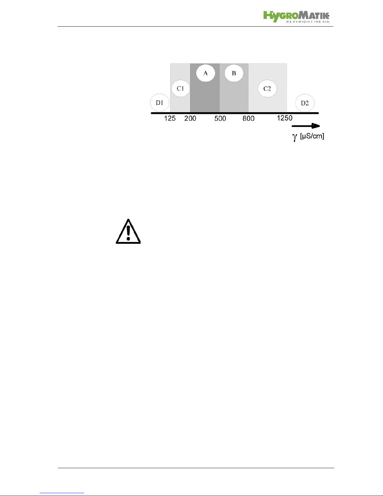
Use feed water with a conductivity between 125 and 1250 µS/
cm only
D1: Lower threshold
C1: Range of reduced conductivity (adjustments recommended)
A: Normal tap water
B: Range of heightened conductivity
C2: Range of high conductivity (adjustments recommended)
D2: Upper threshold
Warning: HygroMatik steam humidifiers emit steam with a temperature of 100° C. The steam may not be inhaled directly.
The HygroMatik Steam Humidifier is not designed for out door fitting
1.2 Typographic Distinctions
• preceded by a bullet: general specifications.
» preceded by an arrow: Procedures for servicing or
maintenance which should or must be performed in the
indicated order.
Installation step which must be checked off.
italics Terms used with graphics or drawings..
Page 7

Page 7
1.3 Documentation
Retention
Please retain these operating instructions in a secure, always
accessible location. If the product is resold, turn the documentation over to the new operator . If the document ation is lost, please
contact HygroMatik.
Versions in Other Languages
These operating instructions are available in several languages.
If interested, please contact HygroMatik or your HygroMatik
dealer.
Page 8
Page 8
2. Safety Notes
2.1 Overview
These safety notes are required by law. They promote workplace safety and accident prevention.
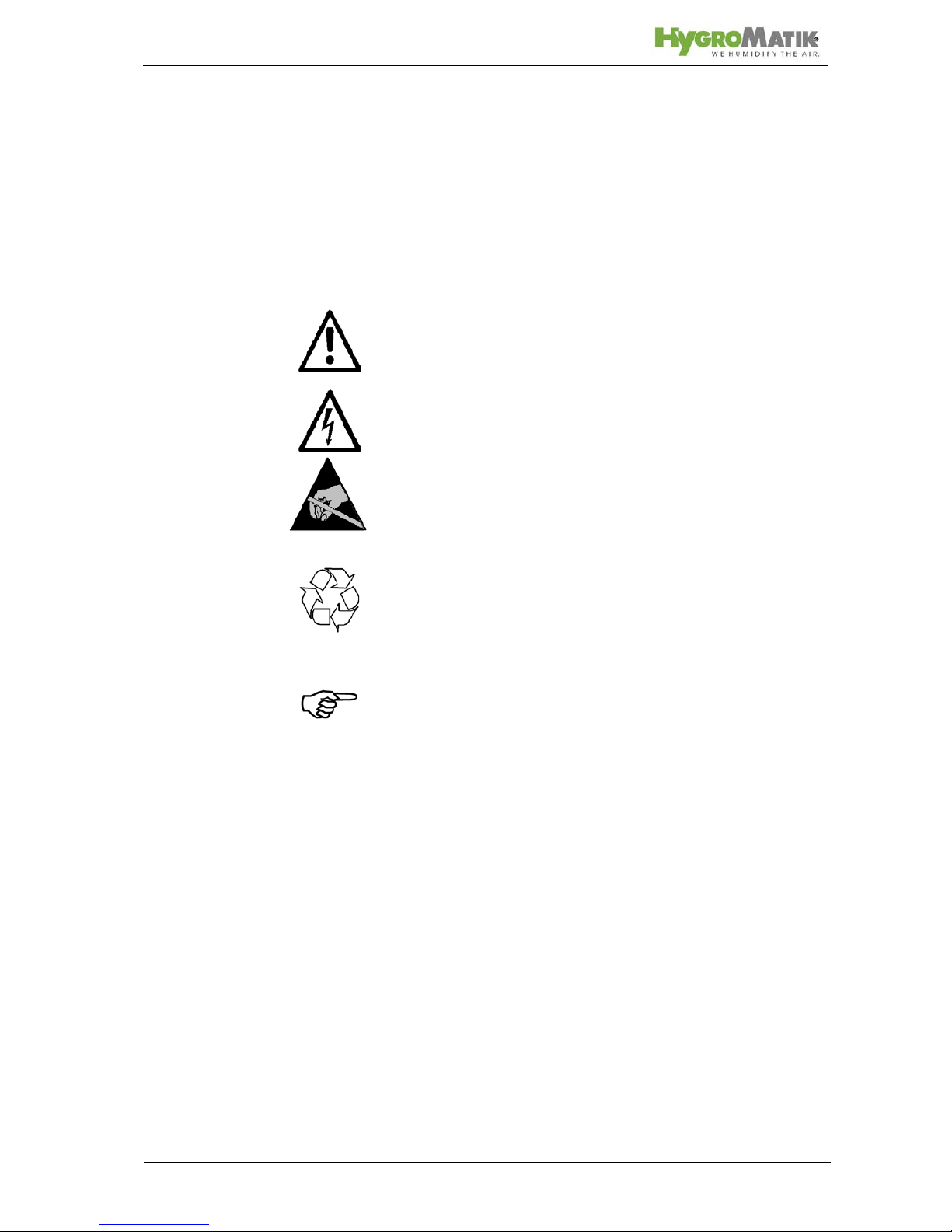
Warnings and Safety Symbols
The safety symbols below identify sections containing warnings
about hazards or potential dangers. Please familiarize yourself
with these symbols.
Warning: Failure to observe this warning may result in serious
injury or death and/or damage to the unit.
Danger, Hazardous Voltage: Hazardous electrical current!
Failure to observe this warning may result in injury or even seri-
ous injury or death.
Warning: Failure to follow these instructions may result in dam-
age to the unit due to electrostatic discharge. The electronic
components of the humidifier control are very sensitive to electrostatic discharges. In order to safeguard these components
during installation and servicing, steps must be taken to protect
against ESD.
Reminder: Materials and consumables must be handled and/or
disposed of as required by law.
Note: Appears before explanations or cross-references which
refer to other sections of the operating instructions.
2.2 Guidelines for Safe Operation
Overview
Obey all safety notes and warnings present on the unit. In case
of a malfunction, switch off the unit immediately and prevent a
restart. Repair malfunctions promptly. After any repair work,
have qualified personnel check the safe operation of the unit.
Use original spare parts only. Additional national safety regulations also fully apply to the operation of this unit.
This unit is not designed for the use by persons (also children)
with limited physical, sensory and mental abilities - or without
knowledge and experience. Unless they are supervised or trained by a person, who is responsible for their safety.
Supervise children in order to ensure that they will not play with
the unit.
The unit is only allowed to work with connected steam hose that
Page 9
Page 9
safely leads the steam.
HygroMatik steam humidifiers are IP20-protected. Make sure
that the unit is protected from drips in its installed location.
Installing a humidifier in a room without water discharge requires
safety devices to protect against water leakages.
Accident Prevention Regulations
Comply with the Accident Prevention Regulation Electrical Systems and Equipment to prevent injury to yourself and others.
Operation of the Unit:
Do not perform any work which compromises the safety of the
unit. Regularly check that all safety and monitoring devices are
functioning normally. Do not remove or disable safety devices.
Installation, Dismantling, Maintenance and Repair of the
Unit:
Disconnect unit components from power supply prior to maintenance or repair work.
Attaching or installing additional components is permitted only
with the written consent of the manufacturer.
Electrical
Work on the electrical system must be performed by qualified
personnel.
Disconnect unit components from power supply prior to work.
It is not allowed to connect the unit to DC voltage supply.
In case of a malfunction in the electrical power supply, switch off
the unit immediately. Use only original fuses with the appropriate
amperage rating. Regularly check the unit's electrical equipment. Promptly repair any damage, such as loose connections,
burned wiring or defective electrical insulation. After proper electrical installation or repair, test all safety mechanisms (such as
grounding resistance).
2.3 Disposal after Dismantling
Note: The operator is responsible for the disposal of unit compo-
nents as required by law.
Page 10
Page 10
3. Transport
3.1 Overview
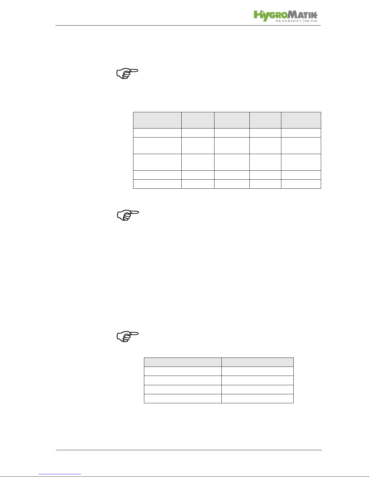
Note: Proceed carefully when transporting the steam humidifier
in order to prevent damage due to stress or careless loading and
unloading.
3.2 Carton outer Size and Weight
3.3 Packing
Note: Notice the symbols affixed to the packing box.
3.4 Interim Storage
Store the unit in a dry place and protect from frost.
3.5 Check for Complete and Correct Delivery of
Goods
Upon receipt of the unit, confirm that:
• the type and serial number on the name plate match
those specified in the order and delivery documents
and
• the equipment is complete and all parts are in perfect
condition
Note: In case of damage during shipment or missing parts,
immediately notify the carrier or supplier in writing.
Time limits for filing freight claims with shipping companies are*:
* Time limits for some services subject to change.
Type* Height
[cm]
Width
[cm]
Depth
[cm]
Weight
[kg]
C01KIT 49 20 29 4
C02KIT -
C10KIT
49 20 29 8
C17KIT C30KIT
66 50 66 12
C45KIT 72 40 40 15
Electronic 16,5 12 9 1
Shipping Companies After Receipt of Goods
Mail no later than 24 hours
Rail no later than 7 days
Truck and Rail Carriers no later than 4 days
Parcel Service immediately
Page 11

Page 11
4. Operation and Installation
4.1 Mode of Operation
The HygroMatik steam humidifier utilizes the conductivity normally present in tap water for steam production. Electrodes
inside an enclosed steam cylinder are immersed directly into the
tap water. They are connected to the alternating current.
The conductivity of the water generates an electric current
between the electrodes. In this way, the electric power supplied
is converted directly into heat without energy loss.
The amperage is a function of the available voltage, the
immersed electrode surface area, the average distance between
the electrodes and the water conductivity. The steam output of
the humidifier is determined by electric power usage, which is
regulated by increasing or decreasing the immersed surface
area of the electrodes.
Concurrently, a self-regulating control keeps conductivity within
a specified range.
The steam produced has a temperature of about 100°C with
minimal excess pressure ("pressureless steam"). It is largely
free of minerals and germ-free. Mineral deposits typically remain
behind in the cylinder.
4.2 Installation and Operation
By pressing the control switch („Pos. I”) the humidifier is turned
on. When the controller specifies an increase in humidity, the
main contactor is switched on and the electrodes (48) are supplied with power. The water inlet solenoid valve (25) feeds water
into the steam cylinder (16+19).
As soon as the electrodes are immersed, the current begins to
flow. The water is now heated. When the pre-selected output is
reached, the control turns off the solenoid valve and interrupts
the water supply.
After a short heating up period, the water between the electrodes begins to boil and vaporize. The vaporization lowers the
water level in the steam cylinder, reducing the output provided.
The inlet solenoid valve, equipped with a fine mesh filter, intermittently admits fresh water.
Humidifier power usage is continuously monitored. With a cold
start-up, the nominal current increases to 125% in order to
achieve quick-start output parameters. This activates the electronic overflow limiter which causes a partial draining of the cylinder. This reduces the immersed surface area of the electrodes,
lowering power usage.
Page 12
Page 12
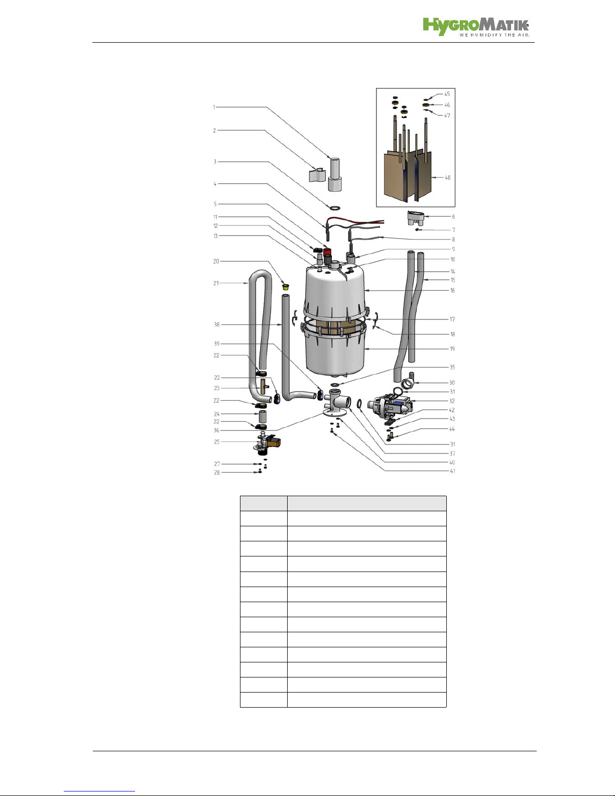
Please also see Section „Exploded View“.
Location Designation
1 adapter
6 vent pipe
10 max. water level sensor electrode
14 water drain, discharge
16 top part of steam cylinder
17 o-ring cylinder flange
18 cylinder flange and o-ring
19 lower part of cylinder
25 solenoid valve water inlet
32 blow-down pump
35 o-ring
37 cylinder base
48 electrodes
Page 13

Page 13
The concentration of dissolved salts increases over time, which
can lead to a rise in the conductivity of the water. If this continues, conductivity may increase until a short circuit occurs. This
could damage the unit, but in any case would significantly
reduce the life span of the electrodes.
For this reason, regular, periodic blow-downs of some of the
concentrated water are very important. Following this procedure
as recommended provides stable cylinder water conductivity as
well as minimal water loss for the expected service life of the cylinder.
Water blow-down is performed by a blow-down pump (32). The
functioning of the blow-down pump is continuously monitored
during operation. If the pump is damaged, the steam humidifier
shuts down.
With normal water quality, the blow-down loss rate is between
7% and 15% of the amount of steam produced. The steam cylinder requires complete drainage every 3-8 days, regardless of
the water quality.
Mineral deposits settle in the open area below the electrodes
and are removed through periodic maintenance. The blow-down
pump itself has wide openings and can flush out smaller pieces
of mineral deposit. This extends the service life of the unit and
reduces the required maintenance interval.
During blow-downs, water flows from the pump into the drainage
system.
A sensor electrode (10) monitors the maximum
water capacity
of the cylinder. When the water level reaches the sensor electrode, the water supply is interrupted. This can occur when the
water has low conductivity or when the electrodes are worn out.
In the case of low water conductivity, however, this state usually
lasts only a short time. The built-in control and the large area
electrodes combine to produce a rapid rise in conductivity by
increasing the concentration of the water.
The steam cylinder consists of a top (16) and lower (19) part
joined with a cylinder flange. The seal between the cylinder and
cylinder base (37), as well as between the top and lower part of
the cylinder, is maintained using an o-ring (35+17).
For maintenance the cylinder can be drained by pressing the
control switch „Pos.II”.
Page 14
Page 14
5. Installation
Warning: Installation of this unit to be attempted only by quali-
fied personnel. We accept no liability for damage due to faulty
installation.
Obey all safety notes and warnings present on the unit.
During installation the unit must be disconnected from its power
supply.
Attaching or installing additional components is permitted only
with the written consent of the manufacturer, or else the warranty is void.
Warning: If the installation of this unit is attempted by only one
person there is a risk that the unit drops down. We propose to
carry out the installation by two persons.
5.1 Steam Humidifier Operating Environment
Note: When selecting the installation site for the steam humidi-
fier, note that:
• Ambient temperature must be between +5° and +40° C.
Relative humidity must not exceed 80% RH.
• An Installation in a closed room requires aeration and if
neccessary temperature conditioning in order to reach
the above mentioned environmental conditions.
• The minimum clearances indicated in the diagram
below must be observed; these are necessary to
ensure adequate ventilation for the housing.
• HygroMatik humidifiers are not suitable for direct outdoor installation.
• The steam humidifier should be installed as close as
possible to the steam manifold. Optimal performance is
guaranteed only with short lengths of steam and condensate hose
.
• Hoses must be laid at a consistent 5-10% incline to prevent sagging and kinking
.
• The rear panel of the steam humidifier heats up during
operation (to a maximum of 60°C).
Take care that the
construction on which the unit is mounted is not made
of temperature-sensitive material.
• Place the steam humidifier so that the unit is easily
accessible with sufficient space to perform maintenance.
• The steam humidifier is not qualified for exterior applications.
Page 15
Page 15
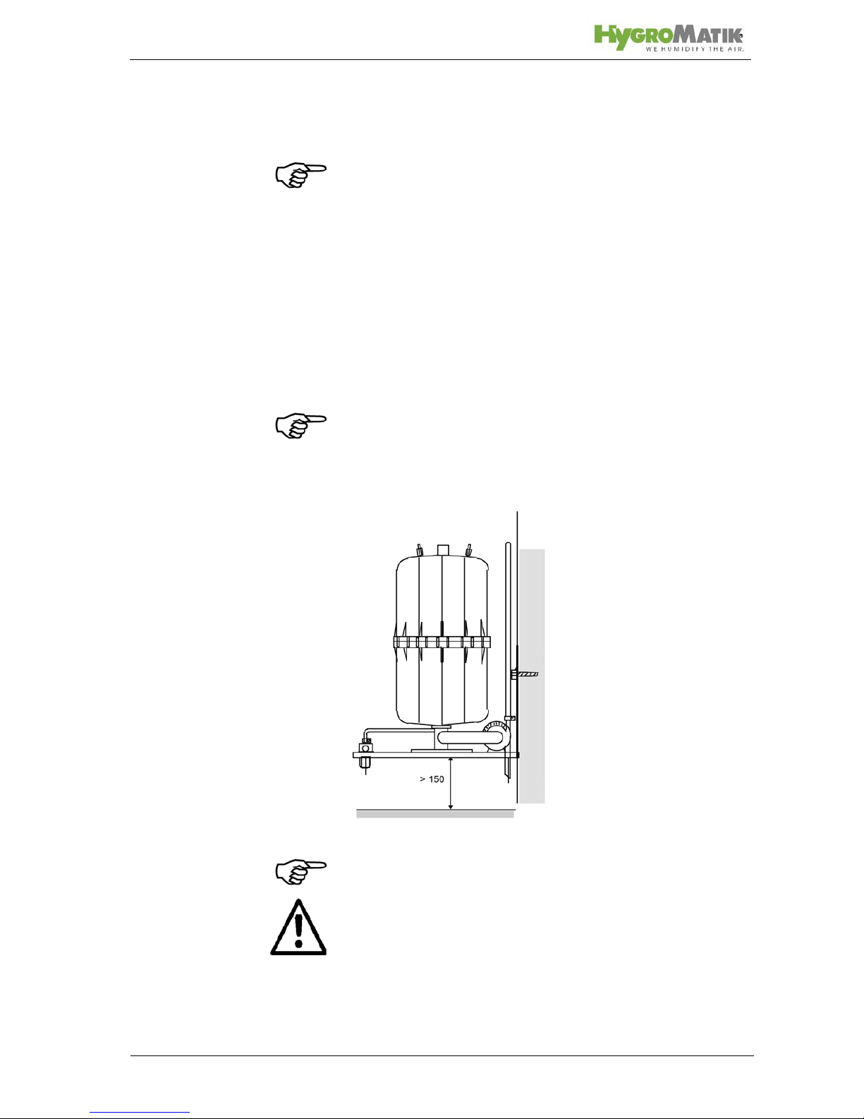
5.1.1 Fitting
Wall Mounting
Note: To function properly the steam humidifier must be installed verti-
cally.
» Position the steam humidifier in the planned location,
adjust with spirit level and mark position of hanging
bolts.
» Hang the unit onto bolts screwed into the marked posi-
tion and tighten.
If there is no suitable wall, it is recommended that the equipment
is installed on brackets which can be embedded in the floor.
Note: The C45KIT cannot be used for wall mounting. The installation has to be done on brackets.
Wall Mounting
Note: To drain properly drain hose system of C17KIT until
C45KIT must be fixed straightly above bracket.
Warning: If the installation of this unit is attempted by only one
person there is a risk that the unit drops down. We propose to
carry out the installation by two persons.
Page 16
Page 16
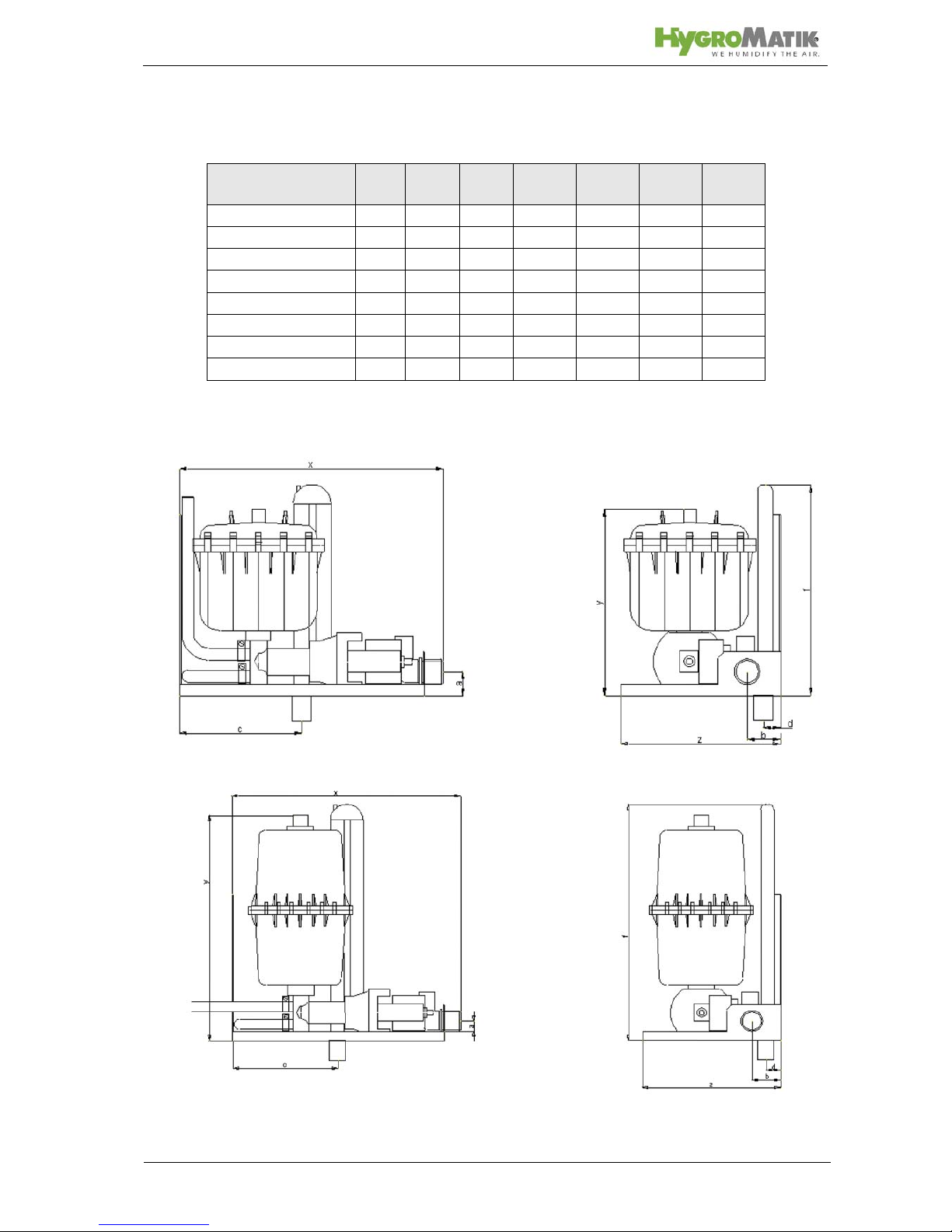
5.1.2 Equipment Dimensions CompactLine KIT
Dimensions DBE 17-45
Dimension [mm] C01
KIT
C02
KIT
C06
KIT
C10
KIT
C17
KIT
C30
KIT
C45
KIT
x 270 270 270 270 328 328 330
y 310 287 365 413 575 575 615
z 175 175 175 175 254 254 316
a 27272727474749
b 35353535555530
c 128 128 128 128 307 307 307
d 20202020232323
f 400 400 400 400 620 620 670
Page 17
Page 17
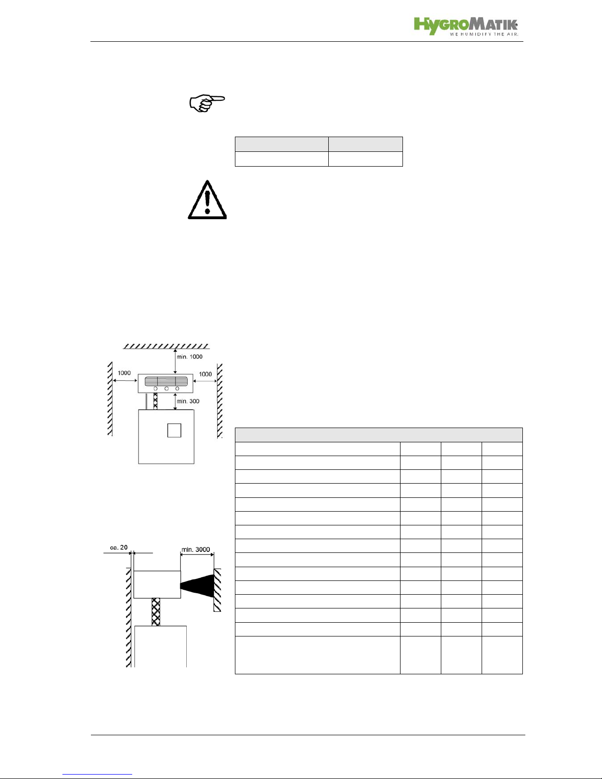
5.2 Fan Unit (optional)
Note: The fan unit should be positioned to avoid drafts . In gen-
eral, a minimum height of 2 m is sufficient.
Install the fan unit directly on a wall.
Warning:
• During operation and a soon afterwards the steam
nozzle is hot! If touched this can cause burns to the
skin.
• During operation the cross-flow fan rotates. Do not
touch the fan during operation.
• During operation hot steam discharges from the nozzle.
In the field of the visible steam cloud contact can cause
burns to the skin.
• During operation the cross-flow fan rotates. Do not
touch the fan during operation.
5.2.1 Fan Unit Type VG
• Install the fan unit over the steam humidifier.
• When employing multiple fan units, do not exceed a
maximum distance of 5 m from the steam humidifier.
• Observe the clearances specified in the diagram below:
Fan Unit Type
for wall installation VG 08, 17, 30
Technical Specifications Fan Unit VG
Fan Unit VG08 VG17 VG30
Quantity of Steam [kg/h] 8 17 30
Steam Inlet [mmφ]25 25 40
Condensate Outlet [mmφ]12 12 12
Airflow Capacity [cbm/h] 185 185 350
Nominal Output [W] 35 35 67
Nominal voltage [V] 230 230 230
Dimensions W [mm] 441 507 550
H [mm] 171 171 171
D [mm] 180 237 277
Weight [kg] 4,5 6 7
Sound Level (1m dis-
tance to the source of
noise)
[dB(A)] 50 57 59
Steam
Front View Wall Installation
Side View Wall Installation
Page 18
Page 18
5.3 Absorption Distance BN
The "absorption distance" (BN) is defined as the distance from
the steam feed to where the steam is completely absorbed in the
treated air. Inside the absorption distance, steam is visible as
mist in the air stream.
Condensation may collect on anything installed inside the
absorption distance.
Although steam outside the absorption distance (B
N
) is com-
pletely absorbed, it is not yet evenly diffused in the duct. If you
plan to install any parts or devices inside the absorption distance, such as sensors or elbows, we recommend increasing
the absorption distance using the formulae below. The absorption distances required for certain installed fittings are distinguished by separate symbols and calculated as a multiplier of
the absorption distance B
N
.
The absorption distance has no fixed value, but depends on
many factors. These are depicted in the absorption distance
nomogram below.
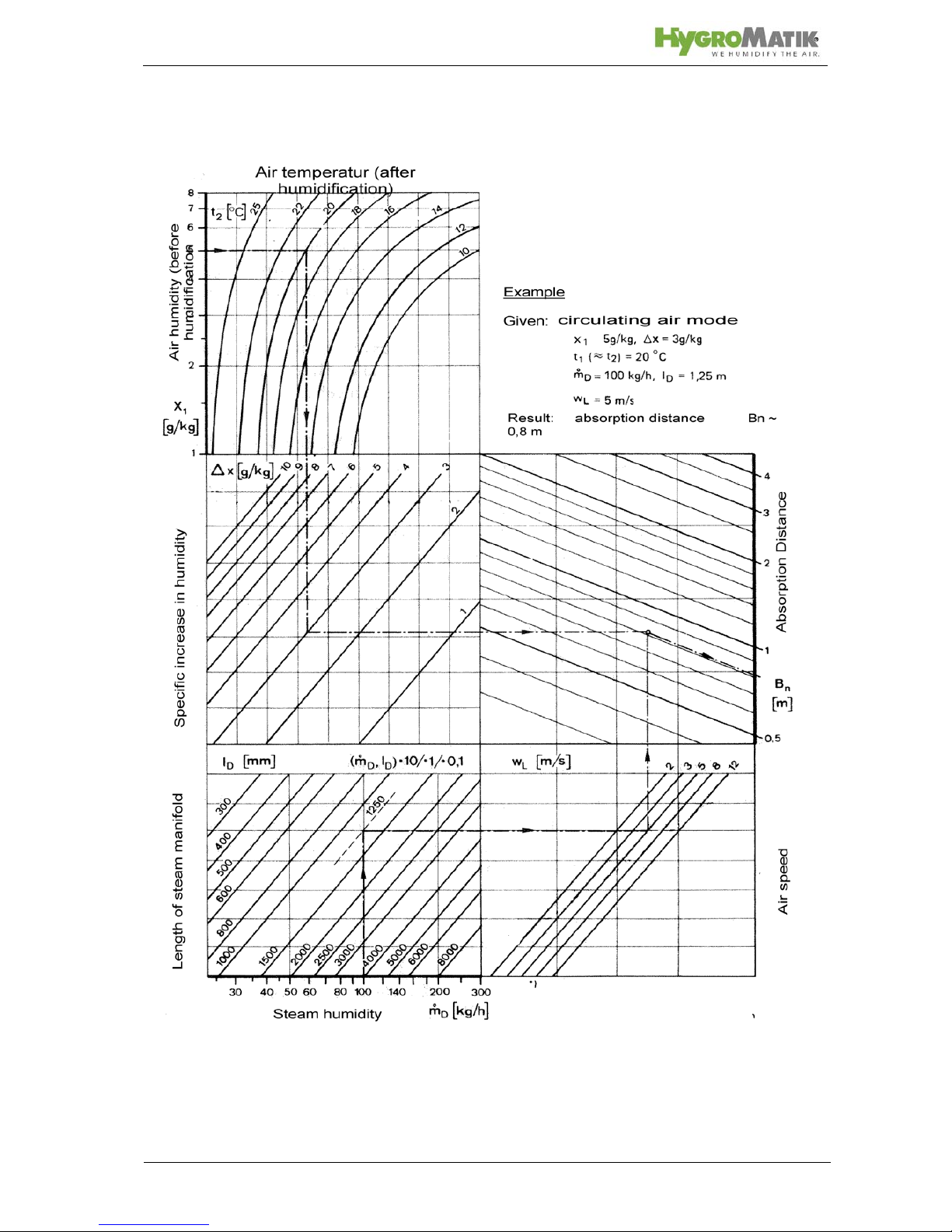
5.3.1 Determining the Absorption Distance
To determine the absorption distance, the following parameters
are required:
• Air humidity before humidification x
1
in g/kg.
• Air temperature after humidification t
2
in °C (with steam
humidifiers the change in air temperature due to humidification may be disregarded t
1
or t2).
• Specific increase in humidity x in g/kg (can be determined in the h,x diagram)
• quantity of steam introduced in kg/h.
• air speed w
L
in m/s in air duct
• Total length l
D
of the steam manifold installed in the air
duct
Absorption Distance
B
N
for normal obstructions, such as sensors, ventilators, outlets
B
c
= (1,5...2) x BNfor fine filters, heat registers
B
s
= (2,5...3) x BNfor particle filters
B
d
= (2,5...3) x BNfor humidity sensors, duct humidistats
o
D
m
Page 19

Page 19
Length ID of the usable steam manifold depends on the dimensions of the air duct. The length of the absorption distance can
be reduced by using multiple steam manifolds (also see section
on the steam manifold).
Method:
Graphically determine absorption distance B
N
using the absorp-
tion distance nomogram (also see Section „Absorption Distance
Nomogramm“). Enter the value of the parameters enumerated
above into the respective quadrants. The resulting point of intersection indicates the value of the desired absorption distance
B
N
.
Notes:
x
1
: _______________________________[g/kg]
t
2
: _______________________________[°C]
x:_______________________________[g/kg]
:_______________________________[kg/h]
w
L
: _______________________________[m/s]
l
D
: _______________________________[mm]
Air humidity before humidification
Air temperature after humidification
Specific increase in humidity
quantity of steam introduced
air speed t
Total length of the steam manifold
o
D
m
Page 20
Page 20
5.3.2 Absorption Distance Nomogram
Source: Henne, Erich: Luftbefeuchtung (Air Humidification), 3rd Edition 1984 (Page 101), Oldenbourg Industrieverlag, Munich
Page 21
Page 21
5.4 Steam Manifold
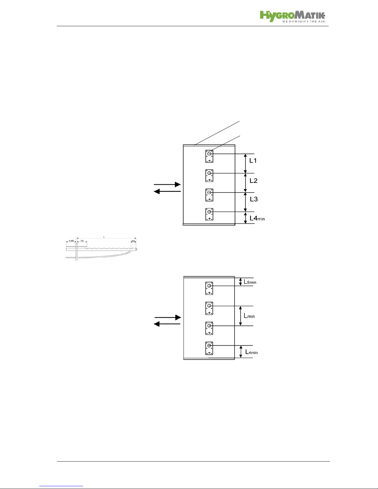
5.4.1 Notes on Installation
These notes are based on a homogeneous
Standard steam manifold installation:
An even distribution of steam manifolds ensures a uniform steam
distribution.
Please use the total hight of the duct!
Minimum distances in order to avoid condensation:
L
min = 210mm: distance „ steam manifold - next steam mani-
fold“
L4
min = 120mm: distance „lowest steam manifold - duct bot-
tom“:L5
min = 120mm: distance „highest steam manifold - duct
ceiling“Installations depending on special designs of air ducts:
Horizontal installation of
steam manifold
Steam Manifold
L1=L2=L3
Duct
Steam Manifold
Air flow
Air flow
direction
Page 22
Page 22
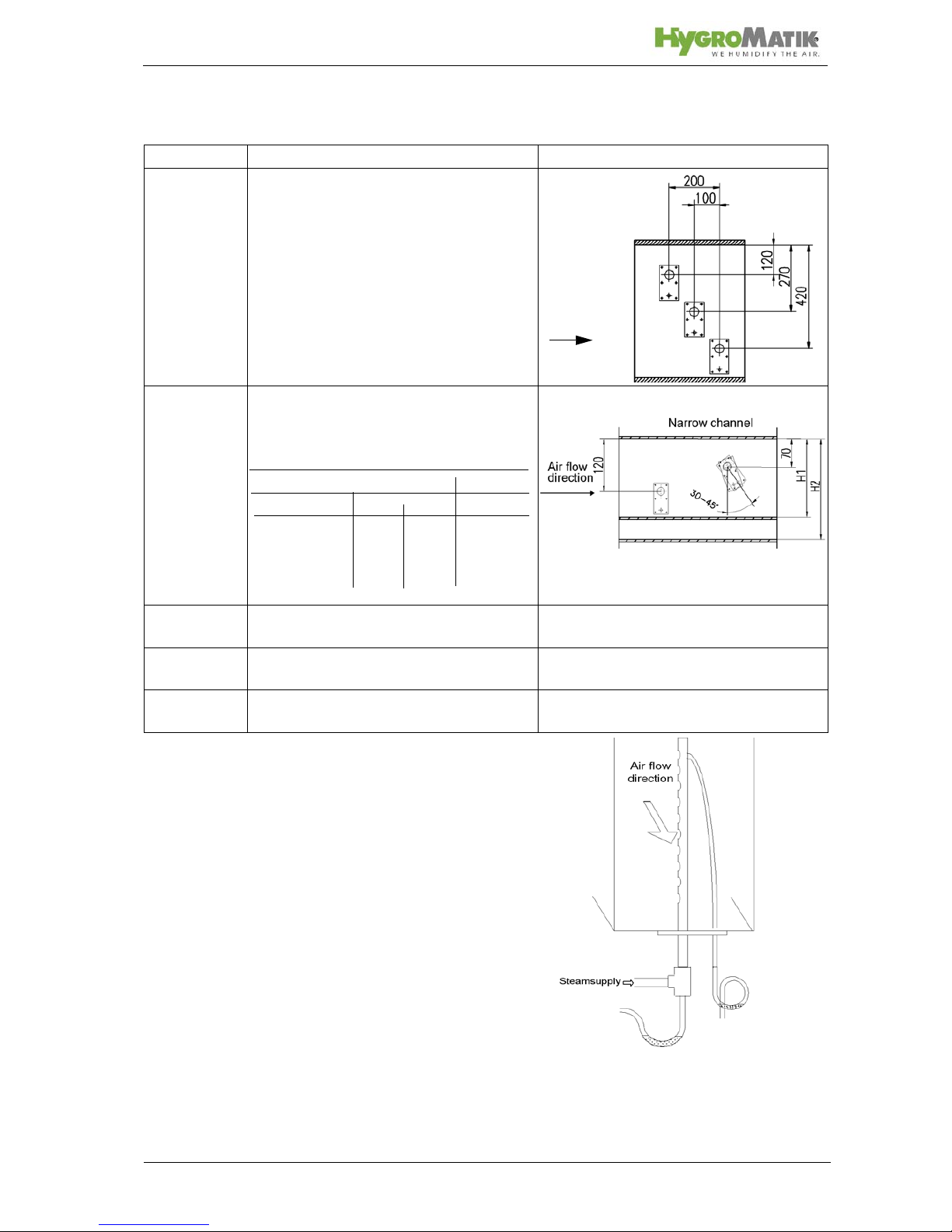
Steam manifold
placement:
Horizontal installation of the steam manif olds is preferred. However, installation from below into the air duct is possible.
Air duct Positioning of steam manifolds Sample
flat Staggered vertically and laterally
Air flow
very flat By tilting the steam manifold 30 - 45°
towards the air flow direction, the minimum upper clearance can be reduced
to 70mm.
min. distances: H1[mm] H2[mm]
30° 45°
DN25 182 168 225
DN40 193 179 230
very flat duct
narrow, high Identical lenghts one on top of the other.
Staggered laterally if possible.
square Identical lenghts, staggered vertically
and laterally
low, very
wide
facing each other
Vertical installation of
steam manifold
Page 23
Page 23
Note:
• Install the steam manifold horizontal with it ensure a clean
steam out.
• Maximum allowable pressure in the air duct is 1200 Pa.
• On the return side, the maximum allowable negative air
pressure is 500 Pa. Placement of the steam manifold on
the supply side of the air duct is preferred.
• With high-pressure air-conditioning systems, the unit's
drain hose system must be modified depending on the
over pressure. When this is the case please consult
HygroMatik.
• Install the steam manifold as close as possible to the
steam humidifier in order to minimize steam loss through
condensation.
• Depending on the design of the air duct, additional moun-
ting of the steam manifold may be required. Shown installation and position dimensions are based on experimental
values. Special environmental conditions could require
adjustments.
• We note that the German Association of Engineers (VDI)
Guideline 6022 specifies a water drain within the absorption distance inside the air duct.
• For steam bath applications: Install the steam manifold
safe from contact with people in order to prevent injuries or
burns. Do not install the steam manifold near a tempera-
ture sensor or inaccurate readings may result.
• Air flow rates over 3m/s can possibly lead to condensate
drainage problems at the steam manifolds which may
require adaptation measures.
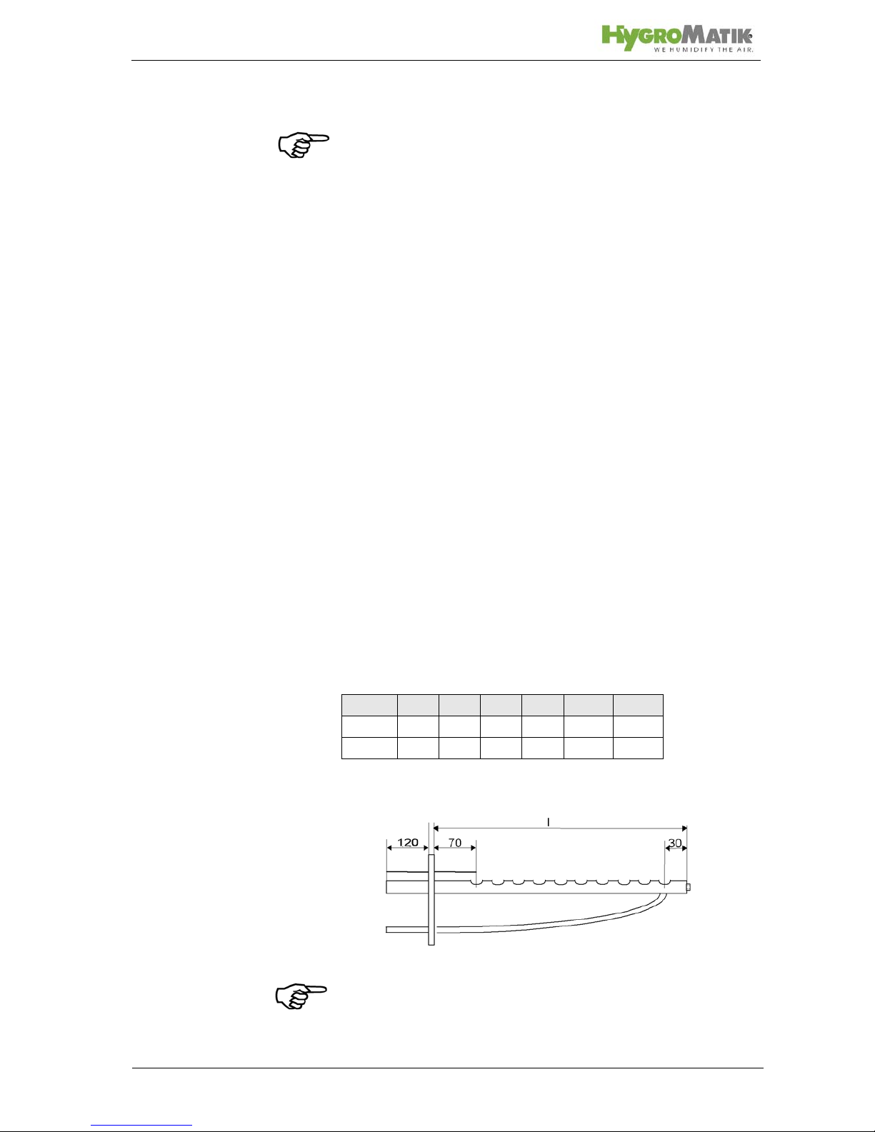
Length of steam manifold [mm]*:
* special lenght on request
Note: At lengths of 600mm or more, steam manifolds are
shipped with an extra alternative mounting fixture (Nut, M8) on
the closed end.
l 220 400 600 900 1200 1450
DN25xxxx x x
DN40xxxx x x
Page 24
Page 24
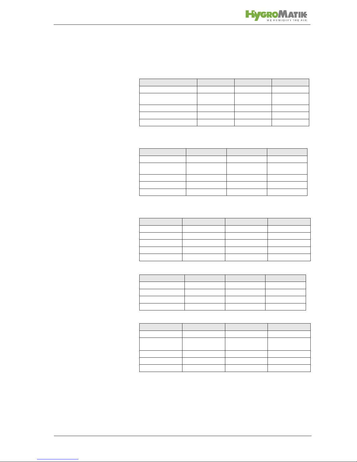
The number and size of appropriate steam manifolds, as well
the nominal width of their respective steam and condensate
hoses, are found in the tables below.
HyLine:
CompactLine:
HeaterCompact/Kit:
CompactLine Kit:
HeaterLine:
* For units HL 6 - 12 and HC3-12 HygroMatik delivers one adapter DN40 / 25 (but not for
SPA applications)..
** For units HL 36 - 45 HygroMatik delivers one t-connector for separating the steam on
two steam manifolds.
***Hl 60.-90 are double units and consist of Hl 30-45 units.
Type Steam Manifold Steam Hose Condensate hose
HY05-HY17 1xDN25 DN25 DN12
HY05DS - HY17DS (for
SPA)
1xDN40 DN40 DN12
HY23-HY30 1xDN40 DN40 DN12
HY45-HY60 2xDN40 2xDN40 2xDN12
HY90-HY116 4xDN40 4xDN40 4xDN12
Type Steam Manifold Steam Hose Condensate Hose
C1-C17 1xDN25 DN25 DN12
C10-DS, C17DS
(for SPA)
1xDN40 DN40 DN12
C22, C30 1xDN40 DN40 DN12
C45** 2xDN40 DN40 DN12
C58 2xDN40 2xDN40 2xDN12
Type Steam Manifold Steam Hose Condensate Hose
HC02/Kit 1 xDN25 DN25 DN12
HC03-12* 1xDN25 DN25 DN12
HC03-12/Kit 1xDN40 DN40 DN12
HC16-27/Kit 1xDN40 DN40 DN12
HC3-27 (for SPA) 1xDN40 DN40 DN12
Type Steam Manifold Steam Hose Condensate Hose
C01 Kit - C06 Kit 1x25 DN25 DN9
C10 Kit - C17 Kit 1x25 DN25 DN12
C30 Kit 1x40 DN40 DN12
C45 Kit 2x40 DN40 DN12
Type Steam Manifold Steam Hose Condensate Hose
HL 6-12 * 1xDN25 DN25 DN12
HL 6-12
(for SPA)
1xDN40 DN40 DN12
HL 18-30 1xDN40 DN40 DN12
HL 36-45 ** 2xDN40 1xDN40 1xDN12
HL 60-90 *** 2x(2xDN40) 2x(1xDN40) 2x(1xDN12)
Page 25

Page 25
5.5 Steam Line
Note: When installing the steam hose, please pay attention to
the following:
• The steam hose diameter may not be smaller than the
steam outlet of the HygroMatik steam humidifier (do not
restrict the cross-section, otherwise back pressure will
increase).
• The steam hose must be without sags and kinks and be
laid with a continuous slope of 5-10% (otherwise sags will
be formed).
• The steam hose should be as short as possible. In case of
lengths of over 5 m the hose should be insulated to avoid
excess condensation.
• In the case that steam output is distributed on two steam
manifolds the T-pieces for the steam and conde nsate hose
should be installed near the manifolds. If the installation is
carried out in this way only one steam hose is necessary
for the main part, loss of condensate will be decreased.
• Depending on how the hose is laid, hose clips should be
set at intervals of approx. 500 mm.
• Allow access to the steam hose, so that it can be inspec-
ted later.
• In case of straight lengths of several meters, it is recom-
mended to place the steam hose in temperature resistant
plastic pipe (40 mm dia for hose DN25; 60 mm dia for hose
DN40) or to use copper pipe.
• Only genuine HygroMatik hoses are capable of withstan-
ding the operating conditions. Allow for minimum bending
radii:
Steam hose DN 25: Rmin = 200 mm
Steam hose DN 40: Rmin = 400 mm
Page 26
Page 26
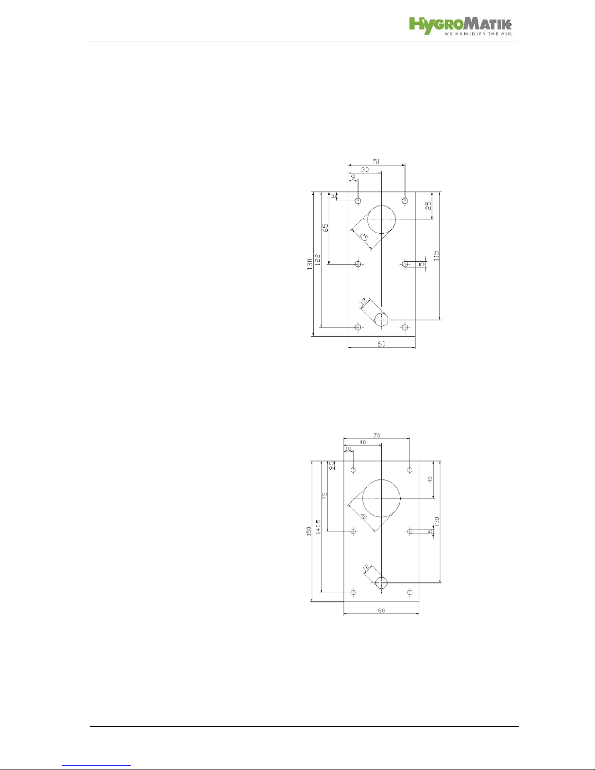
5.6 Cover Plate
HygroMatik flange plates may be used to neatly complete installation of the steam humidifier in the air duct.
Two-piece flange plates are available for the DN25 and DN40
steam manifolds.
flange plate DN25 E-2604260
flange plate DN40 E-2604410
Page 27
Page 27
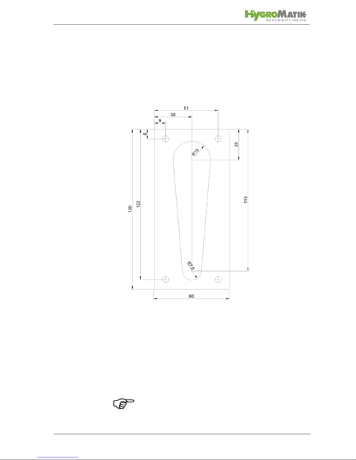
5.7 Drill Pattern
5.7.1 Drill Pattern DN25 (not to scale)
Note: Due to variable print media the dimensions are not to
scale.
Page 28
Page 28
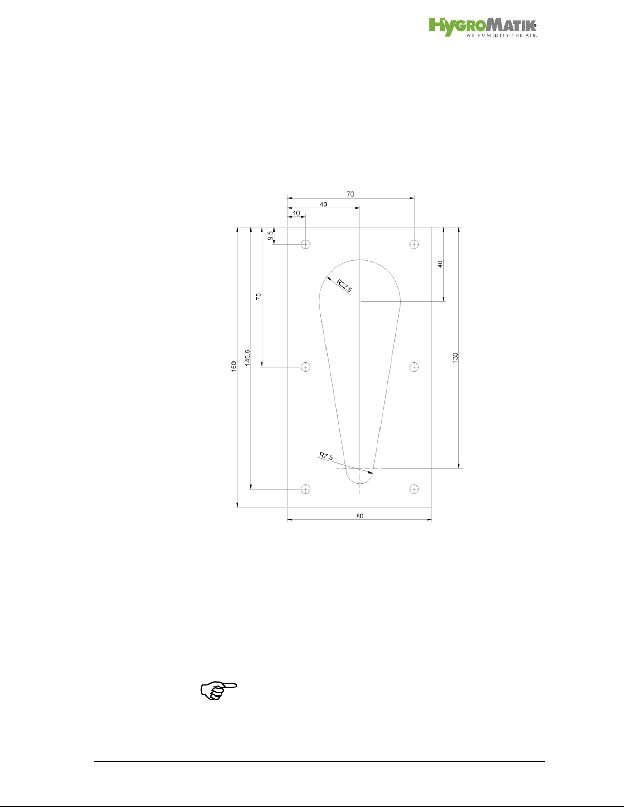
5.7.2 Drill Pattern DN40 (not to scale)
Note: Due to variable print media the dimensions are not to
scale.
Page 29
Page 29
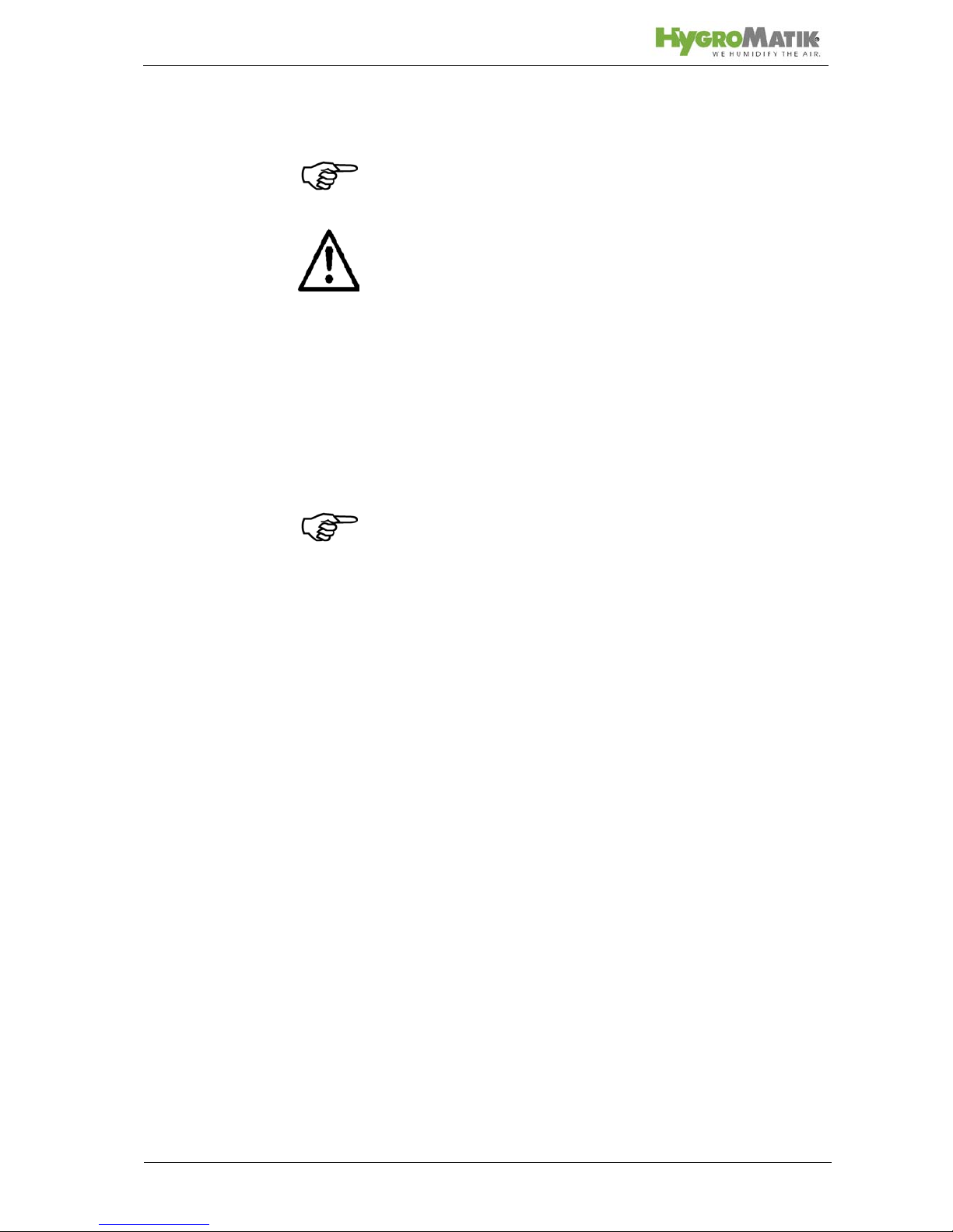
5.8 Condensate Hose
Note: When installing the condensate hose, please pay atten-
tion to the following:
Warning: To keep condensate from accumulating in the duct,
make sure condensate can drain freely.
If the steam manifold is positioned higher than 500 mm
above the steam humidifier:
» Remove the condensate plug (12) from the connection
fitting on the cylinde.
» Lay the condensate hose at an approximate incline of
5-10% to the steam cylinder connection fitting, to allow
the condensate to drain freely.
Note: It is recommended to form a loop of 200 mm diameter as
a vapour trap provided there is enough space.
If the steam manifold is positioned lower than 500 mm
above the steam humidifier:
» The condensate must be drained separately.
» To prevent steam loss, lay a loop at least 200 mm in di-
ameter.
» To ensure condensate drainage, place the loop (vapor
trap) as far away as possible below the steam manifold
connection.
» The condensate connection on the steam cylinder (16 +
19) must be closed with a sealing cap.
» Place hose clamps at intervals of at least 500 mm, de-
pending on how the hose is laid.
5.9 Types of Installation
The steam manifold is positioned higher than 200 mm
above the steam humidifier.
» Lay the steam hose at a height of at least 400 mm and
then connect to the steam manifold with a constant rise
or fall.
» Lay condensate hose with a slope to the steam cyl-
inder.
Page 30
Page 30
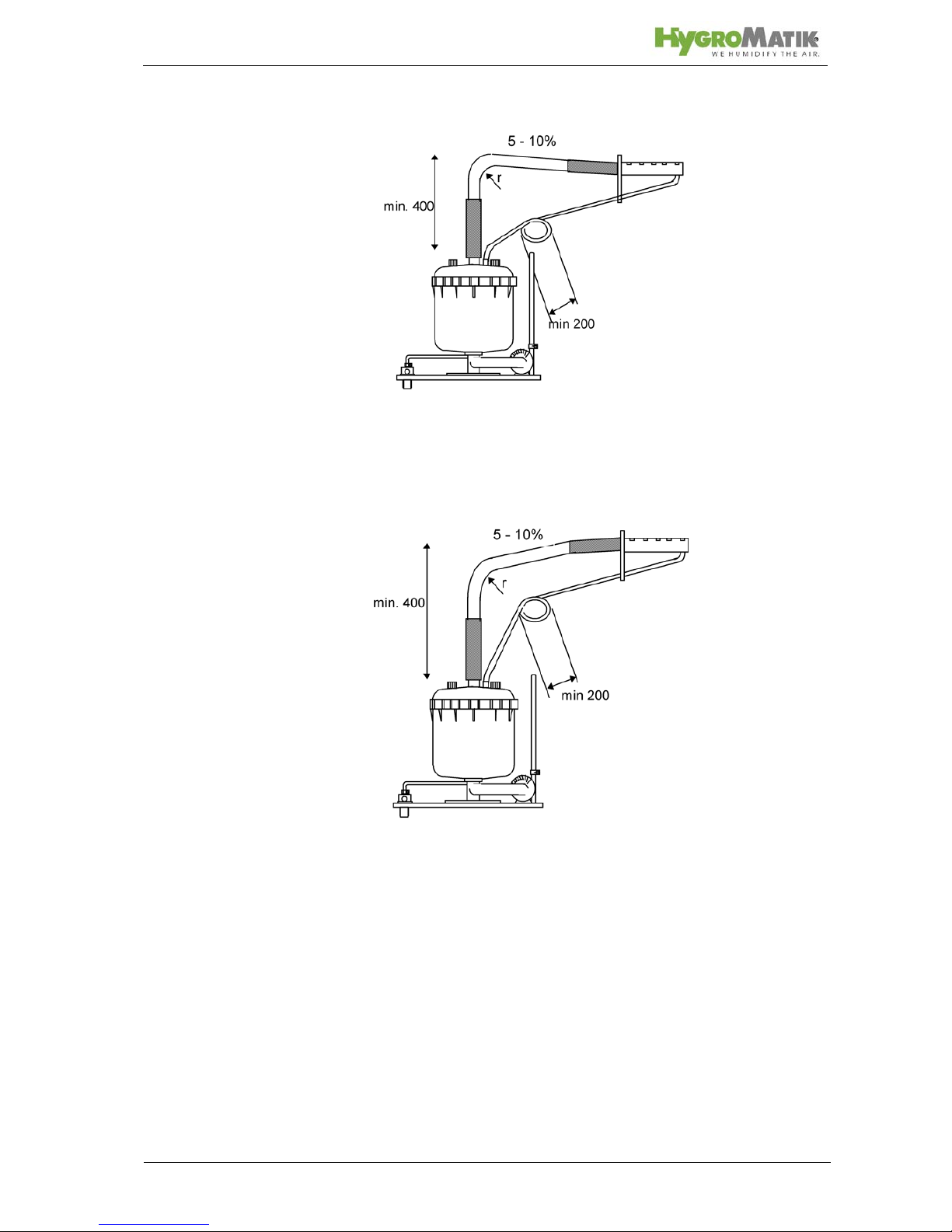
Steam hose with falling slope
Steam hose with rising slope
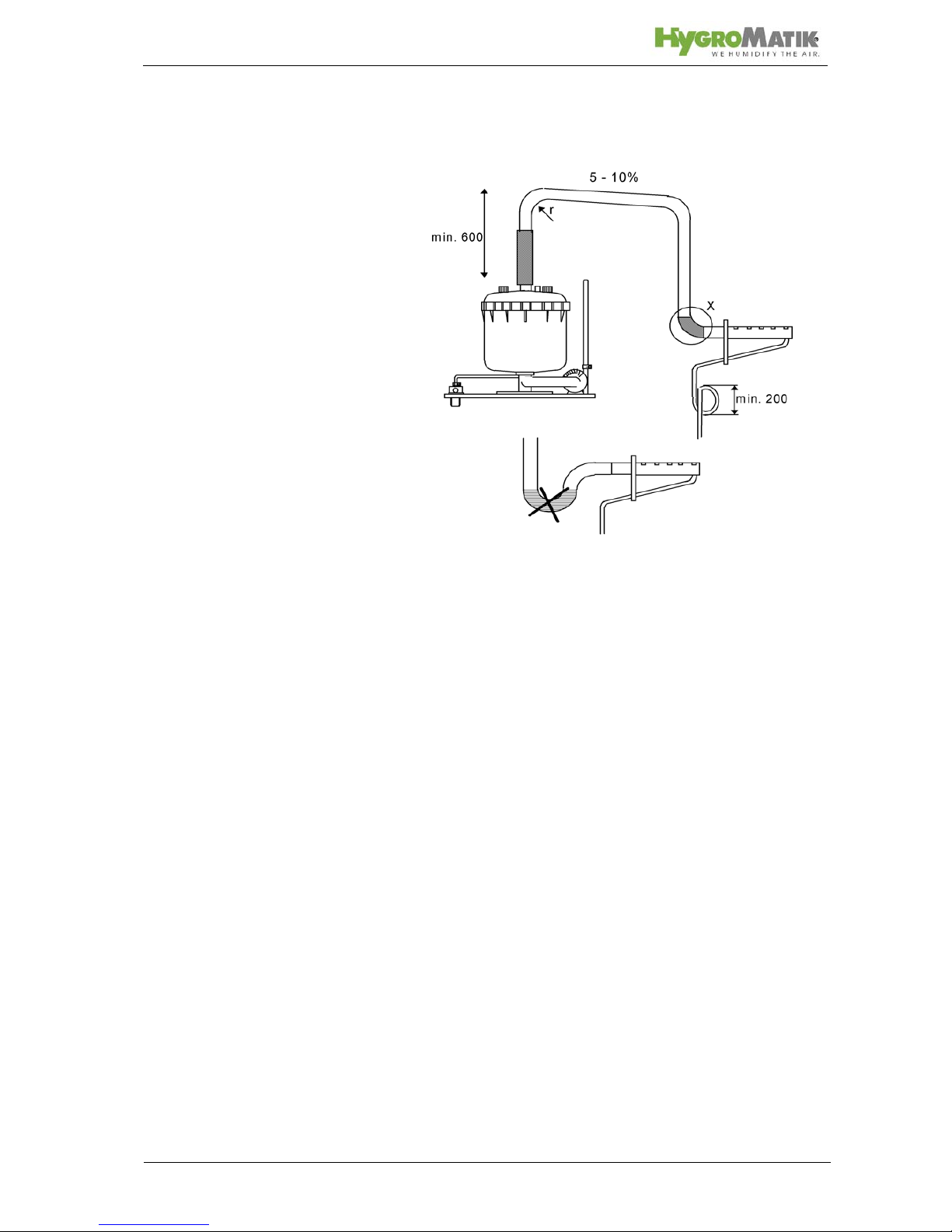
Steam manifold is positioned below the steam humidifier.
» Lay steam hose at a height of at least 400 mm and then
connect to the steam manifold with a constant fall.
» Lay condensate hose with a loop of 200 mm diameter
to the drain.
Page 31
Page 31
Detail X:
wrong!
Page 32
Page 32
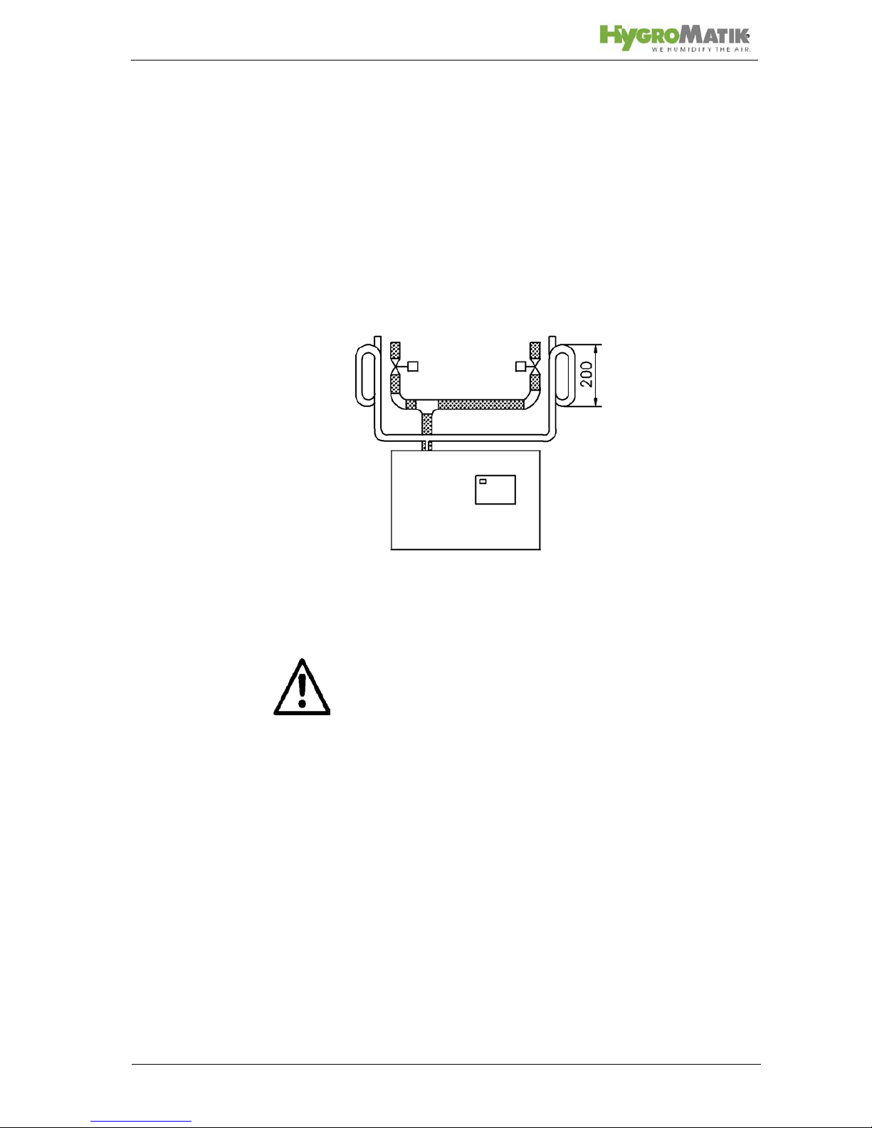
5.10 Steam Solenoid Valves
When humidifying a number of loads, which are to be controlled
separately, using a single steam humidifier, steam solenoid
valves can be included in the steam hoses. Valve control has to
provided by the customer.
• Install the vertical risers with flow from bottom to top.
• The best position is just above the steam humidifier.
Installation of Steam Solenoid Valve
5.11 Unit Installation Check
Attention: This unit may only be operated by qualified and prop-
erly trained personnel.
Please check the installation using the following list:
Does unit hang vertically?
Are wall distances to the unit within the range
Does steam hose have a slope of 5-10%?
Is condensate hose installed with a loop of min. 200
mm?
Is steam manifold positioned correctly? Are all bolts and
clamps tightened?
Page 33
Page 33
6. Water Installation
Warning: When installing the water installation, note the follow-
ing:
• Have all work performed by a professional.
• Disconnect power supply before installation.
• Obey local public utility
regulations
• Verify that necessary safety measures have been taken
– in compliance with either German Technical and Scientific Association for Gas and Water (DVGW) guidelines (DIN EN1717) or local regulations – to eliminate
backflow of polluted water into drinking water treatment
facilities. This can mean installing a backflow preventer .
Within the humidifier, a double check valve (58) is
located in the water supply line. It prevents - in accordance with DIN EN 61770 - the backflow of water.
• Use feed water without chemical additives and with a
conductivity between 200 and 800 µS/cm only. Above
conductivity levels of 800µS/cm to a maximum of
1250µS/cm and below conductivity levels of 200µS/cm
to a minimum of
125µS/cm, special adjustments are
required. In this case please contact HygroMatik.
• The water supply temperature may not
exceed 40° C.
• Water installation pressure: 1 - 10 bar (100 x 10
3
to 100
x 10
4
pascal).
• Blow-down water must be able to drain.
• For water installation please use the water connecting
hose that is delivered with the unit.
6.1 Operation with Softened Water
Warning: Unless special measures are taken, feeding softened
water into the HygroMatik steam humidifier is dangerous. It can
cause
• unacceptably high conductivity
• the formation of salt bridges between the electrodes
and the electrode leads on the inner surface of the top
part of the steam cylinder
• foaming in the steam cylinder
Salt bridges cause electrical arcs. These are indicated by the
presence of black grooves in the top part of the cylinder. The top
part must be replaced to prevent further damage to the cylinder
material, as well as short circuits which trip main circuit breakers.
Foam comes into contact with the maximum water level sensor
electrode and triggers a signal indicating the cylinder is filled to
capacity, even though this is false and the nominal current has
not yet been reached.
Page 34
Page 34
Note: Please contact HygroMatik if you wish to operate the unit
with softened water.
If using a water softening system, we recommend diluting the
softened water with normal tap water to produce an overall hardness between 4-8°dH. This value can be set lower if the water
does not foam.
When blending softened water with deionized water (conductivity = 5-20 µS / cm) it is to ensure that the mixture neither foams
nor is too low in conductivity.
When feed water contains softened water, the level of conductivity is typically higher at operating temperature. Install a HygroMatik "cylinder star" to extend the service life of the electrodes.
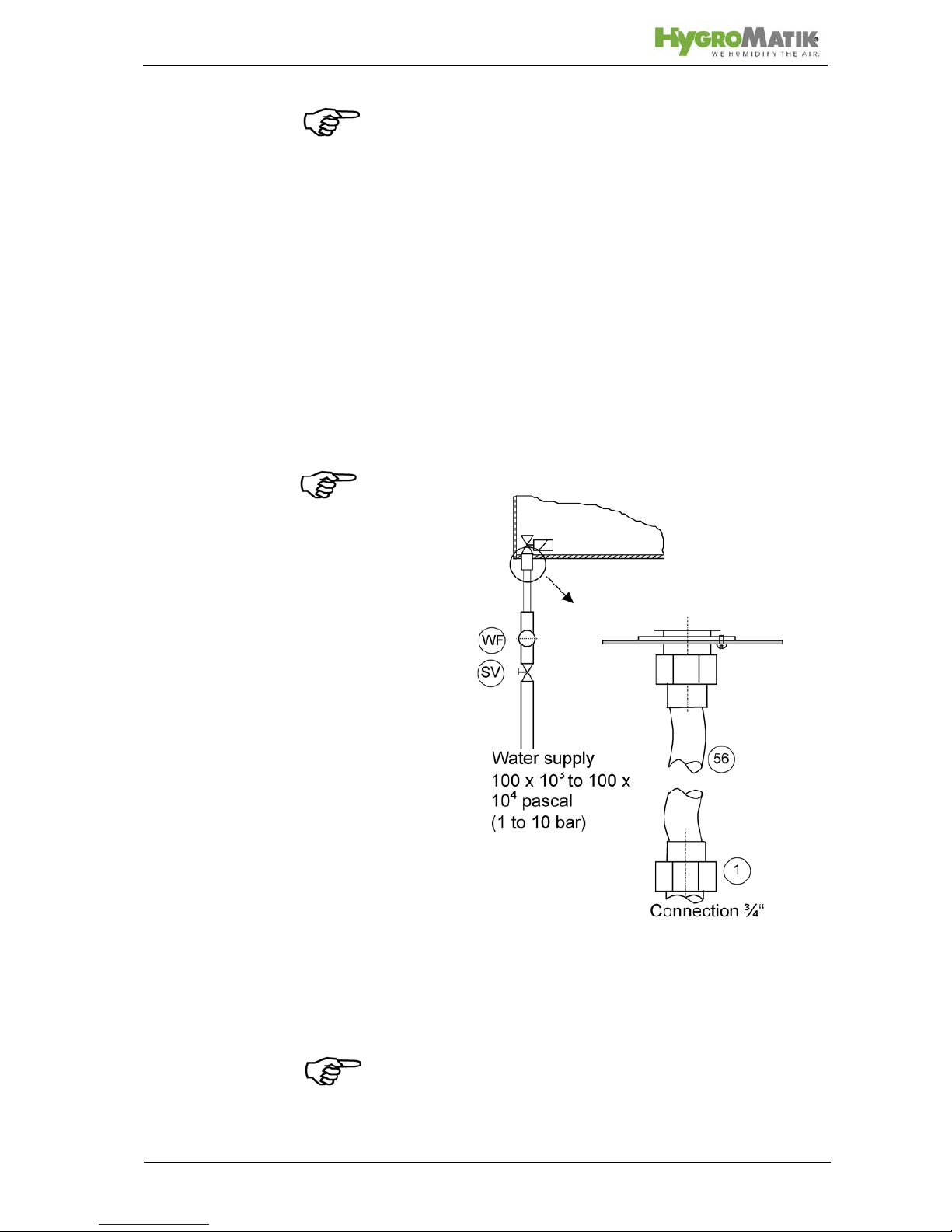
6.2 Water Supply
» Install a shut-off valve (SV) in the supply line.
» Install a water filter (WF) if water quality requires it.
Note: Shut-off valve (SV) and water filter (WF) are not supplied
with the unit
» HygroMatik provides a water hose (56) with a cap nut at
both ends which can be used for water installation.
Install as follows:
» Screw and tighten the cap nut with its inner seal ring
around the water supply screw connection that protrudes from the base.
Note: Tightening too much will destroy the fitting. The valve
strainer must be placed inside the solenoid valve.
Page 35
Page 35
» Use a cap nut (internal thread ¾“) with inner seal for a
customer-provided water installation.
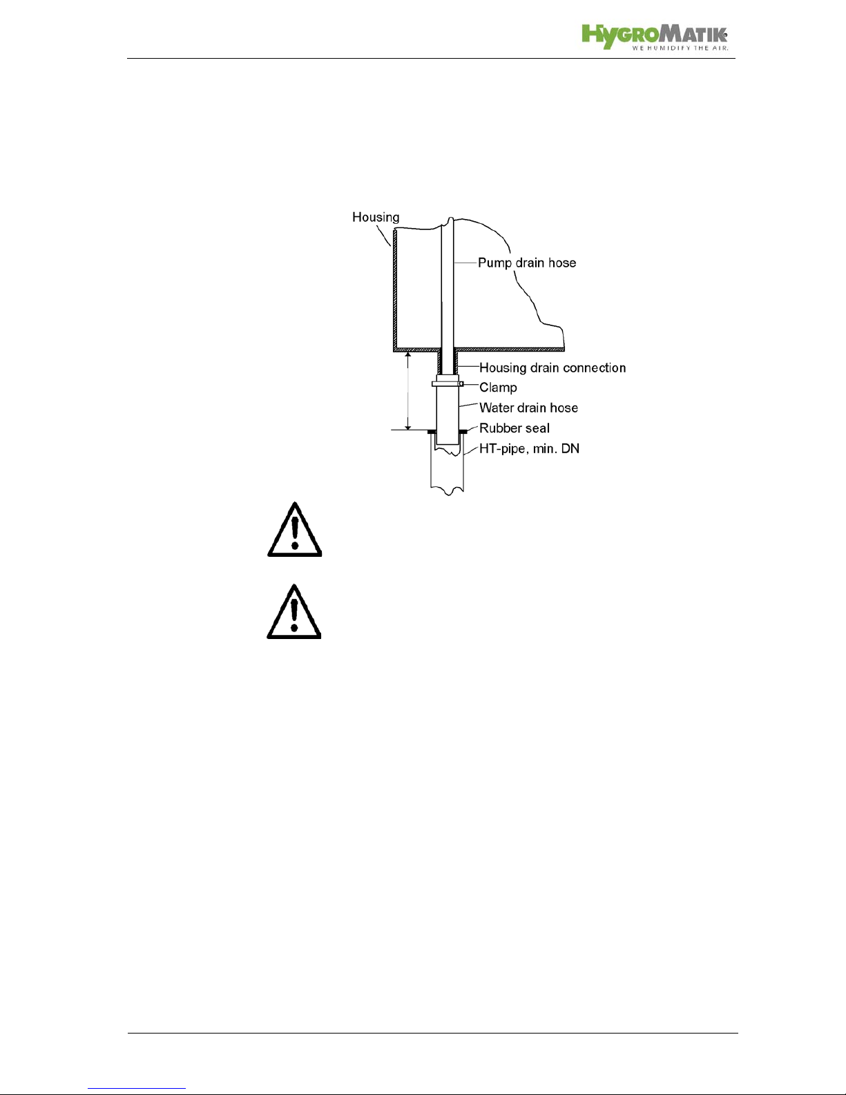
6.3 Water discharge
Warning: During blow down hot water with a temperature of
about 95°C is being drained. If touched this can cause burns to
the skin.
Warning: Pay attention for free and non-pressure drainage of
the water! During blow down up to 0,3 L/sec are being drained.
For water discharge, we recommend installation of a flexible
water drain hose. Humidifier and wastewater discharge must be
on the same pressure level.
Please note:
• Do not bend the drain hose.
• Install discharge line and drain pipe made from temper-
ature resistant material (to 95° C).
Install water discharge as follows
• Loosely insert a length of 1 1/4 " drain hose, approx.
250 - 1000 mm, into a drain pipe with a minimum inner
diameter of 40 mm and seal with a rubber gasket.
• Fit water drain hose over the pump drain hose and fasten to the housing drain connection.
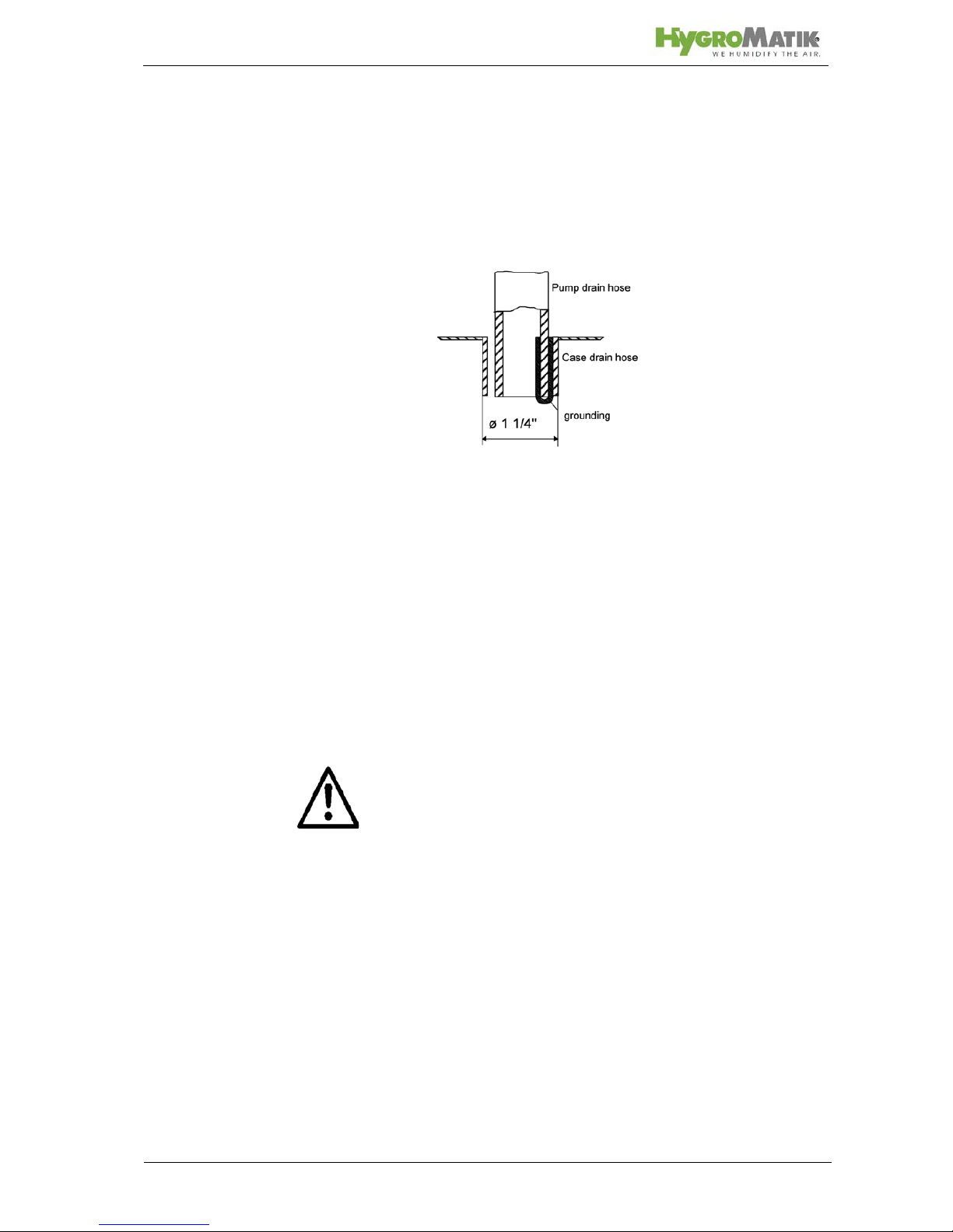
A grounding clip is fixed on the inner surface of the housing
drain connection. The end of the pump drain hose is pushed into
this clip. During blow-down, the grounding clip is in direct contact
with the water and shunts potential residual electric currents
away from the housing.
min.: 250mm
max.: 1000mm
Page 36
Page 36
There is a 3mm-wide crack between the pump drain hose jacket
and the inner surface of the housing drain connection. If water
collects in the base plate, it will flow through this crack into the
drainage system.
6.4 Water Installation Check
Go down the following water installation checklist:
Are all screws and clamps properly tightened?
Is the water supply pipe flushed?
Was the water installation correctly installed?
Can the blow-down water drain freely?
Was the water discharge correctly installed?
Is there no leakage from the water supply pipe and
water discharge?
Warning: Flush the water supply pipe before connecting to the
solenoid valve, especially a newly installed pipe. This prevents
premature damage.
Page 37
Page 37
7. Electrical Connection
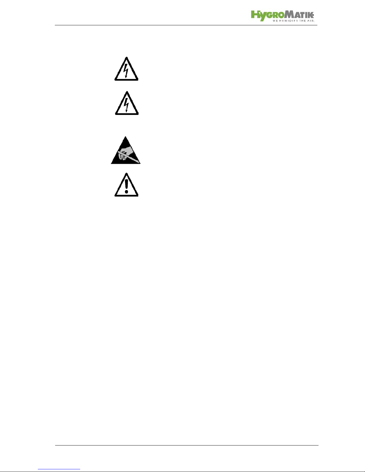
Danger, Haza rdous Voltage: All work related to electrical inst al-
lation to be performed by authorized personnel only (electricians
or professionals with equivalent training). The customer is
responsible for checking qualifications.
Danger, Hazardous Voltage: Do not plug the steam humidifier
into the power grid until after all installation work has been completed.
Please obey all local regulations concerning electrical installation.
Warning: The electronic components of the humidifier control
are very sensitive to electrostatic discharges. In order to protect
these components during any type of installation, steps must be
taken to guard against damage from electrostatic discharge
(ESD protection).
Warning: For electrical installation, note the following:
• Disconnect power supply before installation and protect
against restart.
• Verify the absence of electric current.
• Make sure the unit is switched off before installing or
removing the display plate or basic PCB.
• Professionally lay electrical connector cable.
• Install the electrical connections according to the wiring
diagram.
• For units with rated power over 33 kW, only a permanent connection to a permanent wire is allowable (German Association for Electrical, Electronic & Information
Technologies [VDE] Standard 0700 Section 98).
• Verify that all terminals have been tightened.
7.1 Electrical Installation
» Fuses must have a contact gap of at least 3mm per
pole.
» Install a separate main connection for each steam cylin-
der, complete with main contactor, main switch, etc.
» Connect potential equalization to the outer ground bolt.
» Observe the German Association for Electrical, Elec-
tronic & Information Technologies [VDE] Standard 0100
when selecting a connection cross section.
» Install main power supplies as follows:
Page 38
Page 38
HyLine:
CompactLine:
MiniSteam:
CompactLine KIT:
Other voltages are available on request.
We recommend employing quick or medium blow main fuses (applicable only to the grid voltages above). See table below indicating maximum power usage for each circuit protection:
HyLine:
Type Main Power Supply
HY05 - HY45 1 x 400V/3Phase/N
HY60 - HY116 2 x 400V/3Phase/N
Type Main Power Supply
CompactLine 1 x 400V/3Phase/N
Type Main Power Supply
MS5
MS10
1 x 400V/3Phase/N
MS5 1 x 230/1Phase/N
Type Main Power Supply
C01KIT, C02KIT 1 x 230V/1Phase
C06KIT - C45KIT 1 x 400V/3Phase/N
Type Power Usage Circuit Protection
HY05 5,4 A 3 x 6A
HY08 8,7 A 3 x 10A
HY13 14,1 A 3 x 16 A
HY17 18,4 A 3 x 20 A
HY23 24,9 A 3 x 35 A
HY30 32,5 A 3 x 35 A
HY45 48,8 A 3 x 63 A
HY60 2 x 32,5 A 6 x 35 A
HY90 2 x 48,8 A 6 x 63 A
HY116 2 x 62,8 A 6 x 63 A
Page 39
Page 39
CompactLine:
MiniSteam:
CompactLine KIT:
Type Power Usage Circuit Protection
C6 6,5 A 3 x 10 A
C10 10,8 A 3 x 16 A
C17 18,4 A 3 x 20 A
C22 23,8 A 3 x 35 A
C30 32,5 A 3 x 35 A
C45 48,8 A 3 x 63 A
C58 62,8 A 3 x 63 A
Type Power Usage Circuit Protection
MS5, 230V/1/N 15,7 A 1 x 16 A
MS5, 400V/3/N 5,4 A 3 x 6 A
MS10, 400V/3/N 10,8 A 3 x 16 A
Type Power Usage Circuit Protection
C01KIT 3,3 A 1 x 6 A
C02KIT 6,5 A 1 x 10 A
C06KIT 6,5 A 3 x 10 A
C10KIT 10,8 A 3 x 16 A
C17KIT 18,4 A 3 x 25 A
C30KIT 32,5 A 3 x 35 A
C45KIT 48,8 A 3 x 63 A
Page 40
Page 40
7.2 Safety Interlock
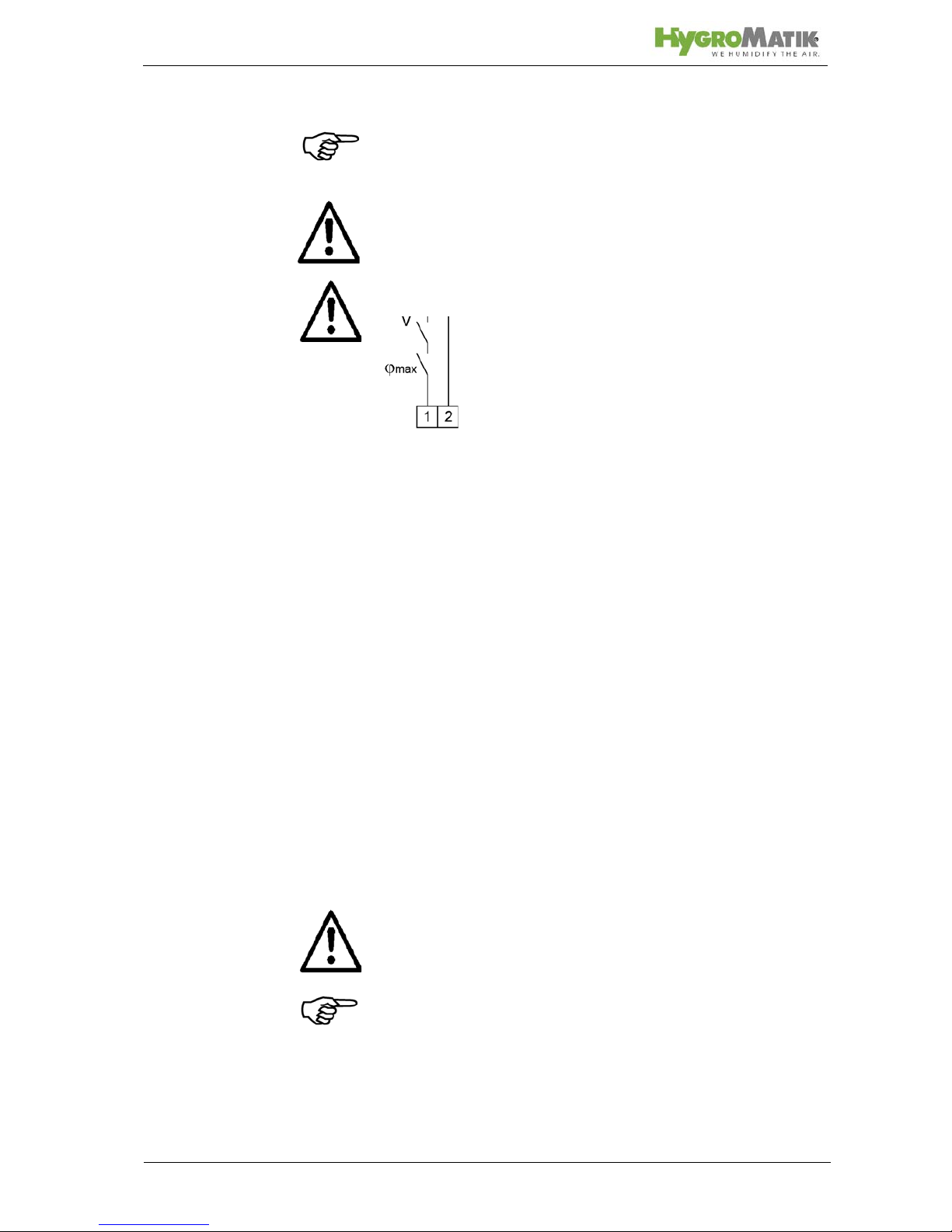
Note: Install contact interlocks, i.e. max. hygrostat, vane relay,
pressure controller, air interlock, in series between terminals 1
and 2.
Warning: A max-hygrostat shou ld be installed in the safety interlock. The max-hygrostat acts as a safety device in case the
humidity sensor malfunctions.
Warning: Contacts laid between terminals 1 and 2 must be
potential free and rated for 230V switches.
7.3 Wiring Diagram
Please remove the wiring diagram from the technical manual
supplied with the control used with your humidifier. Every steam
humidifier comes with one technical manual for the unit and one
for the control.
7.4 Electrical Installation Checklist
Perform electrical installation checks in compliance with customer site requirements and public power utility regulations:
Is the power grid voltage compatible with the voltage on
the name plate?
Have all electrical connections been made according to
the terminal connection diagram?
Have all electrical cable and plug connections been
properly tightened?
Are all electrical socket connections secure?
Is the unit grounded?
After this check the unit can be switched on.
Warning: The unit must be closed and locked. This guarantees
that the cover is grounded. (only humidifier type HyLine and
MiniSteam)
Note: For initial operation, control, service, malfunctions, and
circuit diagrams, consult the operation instructions for the HygroMatik-controls.
Page 41
Page 41
8. Maintenance
The HygroMatik steam humidifier is easy to maintain. However,
inadequate or improper maintenance can lead to operational
malfunctions. Perform regular maintenance to give your unit a
long life span.
Warning: When performing maintenance work, please note:
• During operation and also for a while after switching off
the unit the steam cylinder is hot. Before touching the
cylinder, check its temperature.
• Drained cylinder water could have a temperature up to
95°C.
• Leakages within the humidifier could lead to leakage
currents.
• Observe safety notes.
• Switch off the unit before maintenance and protect
against restart.
• After maintenance work, have qualified personnel
check that the unit is operating safely.
The steam humidifier's performance and maintenance intervals
primarily depend on the water quality (carbonate hardness, conductivity) and the quantity of steam produced since the last
maintenance. Abnormal water quality can shorten or lengthen
maintenance intervals. Ongoing maintenance intervals can be
estimated based on the amount and type of residue found in the
steam cylinder.
Indications that cylinder maintenance is required immediately
include:
Control Indicator
L maintenance message: red LED is blinking:
- Cylinder-Full, delayed *,
- Blow-down Fault *,
-
Filling Fault *.
Unit has switched itself off automatically.
Page 42

Page 42
8.1 Maintenance Work
Mineral deposits precipitate and crystallize very differently in different types of water, even when two types have the same conductivity and hardness levels (the various constituents in the
water interact differently).
Instructions on maintenance and cleaning intervals, or on electrode service life, are based entirely on empirical data.
In most cases, the conductivity levels given in Section 1.1
"Directions for Use" of these instructions can be considered normal. Individual parameter setting of the control may be necessary.
In extreme cases, water pretreatment may be necessary (softening by dilution to approx. 4 - 8 °dH; decarbonization/partial
desalination to achieve target reductions in carbonate hardness). HygroMatik would be pleased to refer you to companies
specializing in water treatment systems.
Cycle Maintenance Work
4 Weeks after
initial operation
(with normal
water quality)
Visual inspection of electrical and
mechanical connections
Remove mineral deposits from steam cylinder, water drain hose and blow-down
pump
Check electrodes for erosion
Semiannually
(with normal
water quality and
"normal" opera-
tion = 8h/day)
Visual inspection of electrical and
mechanical connections
Remove mineral deposits from steam cylinder, water drain hose and blow-down
pump
und ggf. erneuernCheck electrodes for
erosion
Page 43
Page 43
Warning: Both the clamps that fix the steam cylinder halves and
the electrodes have sharp edges and angles that possibly could
lead to cut injuries.
8.1.1 Cleaning the Steam Cylinder
Disassembly
» Drain residual water in the cylinder.
» Press the on/off control switch in position "II".
» Disconnect steam humidifier from power supply. Con-
trol switch OFF and remove safety fuse F1. Secure
against restart.
» Check that unit is without power.
» Lift steam cylinder (16+19) out of base (37) and remove
from humidifier.
» Release its flange clamps (8) and open the cylinder.
Cleaning
Note: When cleaning do not use acids or other chemicals!
» Remove all scale and sludge from cylinder.
» Remove deposit from the heating electrodes (3) by
knocking them (small amounts that remain are acceptable).
» Inspect the inside of the top part of the cylinder for fur-
ring and any electrical bridging (black grooves) between the electrodes and their bushings and remove
completely by washing.
Note: Top half of the cylinder must be replaced if electrical
bridges have penetrated deeply into the material.
» Clean cylinder coarse strainer.
» Restore the surface of the level electrode in the top
part of the cylinder to a bright metal condition.
Page 44
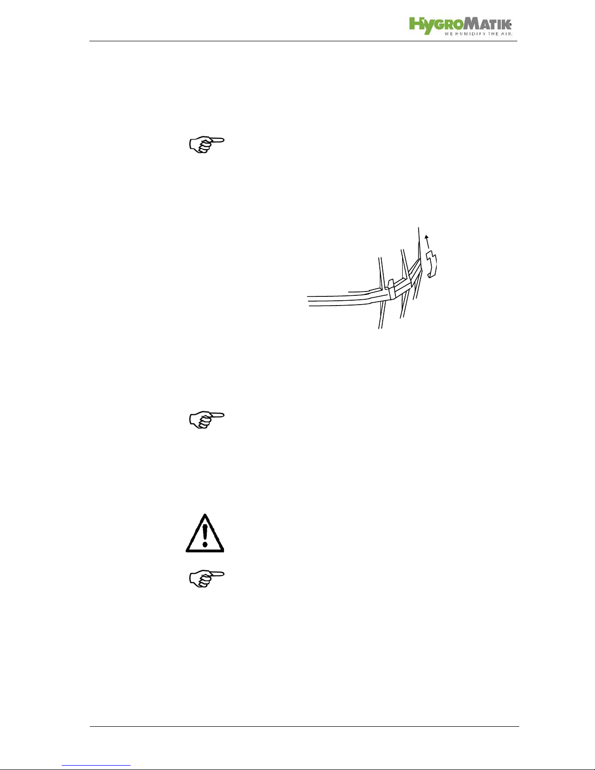
Page 44
Reassembly
» Replace the flange o-ring (13) with original HygroMa-
tik solvent-free, moistened o-ring.
Note: When joining the cylinder the upper and lower parts must
have a firm fit.
» Connect upper (16) and lower parts (19) with clamps
(18).
» Remove o-ring (35) from the lower part of the cylinder.
» Insert a new solvent-free, moistened HygroMatik o-ring
(35) into the cylinder base.
Note: The types C02KIT and C06KIT are supplied with a steam
hose adapter (1). Exchange o-ring if maintenance steam cylinder.
» Refit cylinder firmly into cylinder base (37).
» Connect plug (9) to level sensor.
» Connect plugs (10) to electrodes.
Attention: Check the electrode plugs on the electrodes for firm
seating.
Note: Connect the electrode plugs with the matching electrodes.
Pay attention to the coloured hand nuts (9)!
» Push in safety fuse.
Switch on the unit and operate for 15 to 30 minutes. Check for
any leaks.
Top part of cylinder
Lower part of cylinder
Page 45
Page 45
8.1.2 Electrode Wear
Electrode wear is dependent on:
• feed water quality (conductivity and hardness) and
• generated amount of steam.
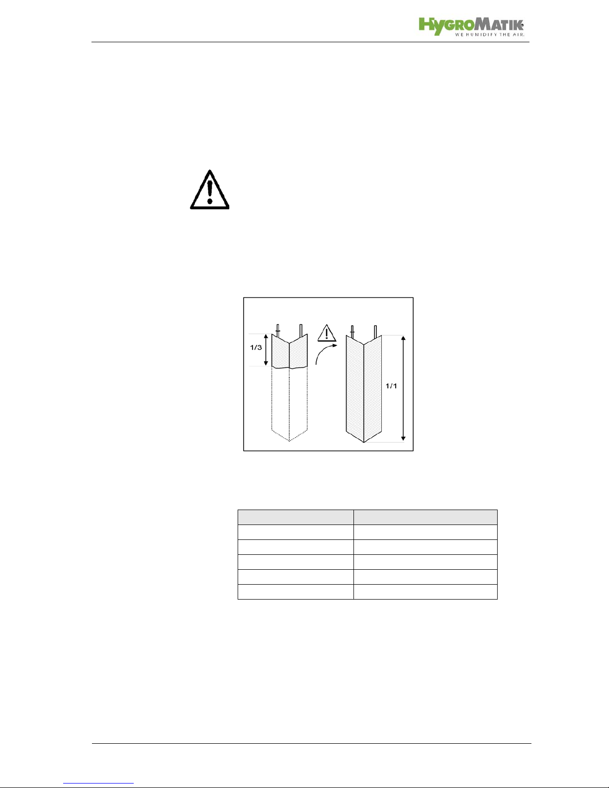
Attention: The electrodes must be exchanged at the latest if the
display shows the message Service (red LED is blinking). The
unit is switched off in case it senses a period of one hour's operation in the "Cylinder full" condition. As a guide they must still be
a third to one half their original length.
The original length of HygroMatik stainless steel large-area electrodes is as follows:
Uneven Electrode Wear
Replace badly worn electrodes completely. Check main fuses !
If a main fuse has blown the corresponding electrode will not be
supplied with power and hence will not wear.
Type lenght [mm]
C01KIT 115
C02KIT 80
C06KIT 125
C10KIT 155
C17KIT-C45KIT 235
Page 46
Page 46
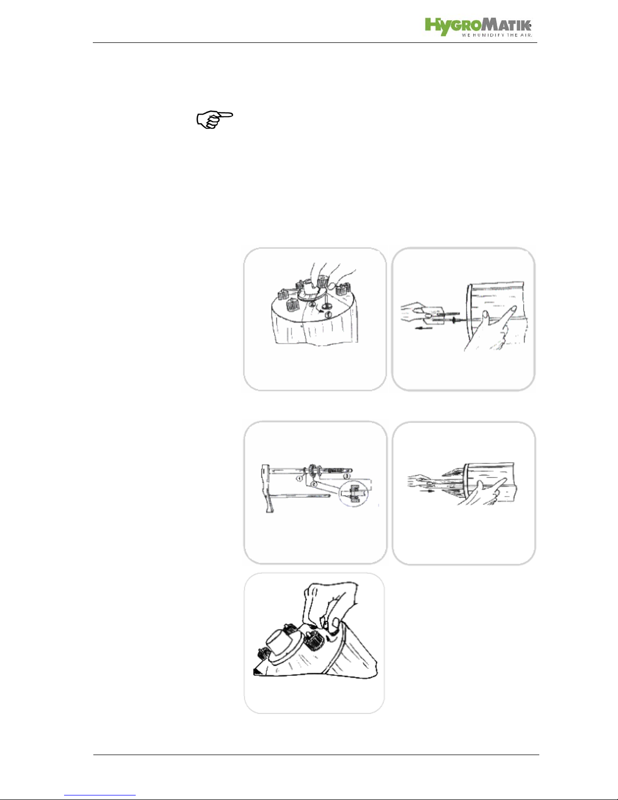
8.2 Replacing Electrodes
Note:
• If electrodes must be exchanged frequently or
• black sludge collects in the cylinder or
• there is arcing in the cylinder
this indicates, that the conductivity of the water is too high, or the
cylinder is not being drained frequently enough. In this case
please contact HygroMatik for advice.
remove electrode
remove handnut
insert electrode
Mount correctly:
1=shaft seal, 2=brass ring
3=O-ring
detailed view
of new electrode
fasten handnut hand-tight
L1=black, L2=red, L3=grey,
B1=grey
Page 47
Page 47
» Remove and open cylinder, as described in Section
"Removing and Cleaning Steam Cylinder."
» Loosen knurled nuts (5) and remove electrodes (48).
» Install new electrodes and hand tighten the nuts.
» Use solvent-free, HygroMatik-quality o-rings (for flange,
cylinder base and steam hose adapter).
» Assemble steam cylinder and place it into cylinder
» Connect plugs (4) directly to the electrodes (48) (with
gray, red and black knurled nuts). It is not necessary to
detach the knurled nuts!
Warning: The plug must be pressed down onto the electrode as
far as it will go.
Note: Connect plugs to the correct electrodes. Pay attention to
the color of the knurled nut.
» Attach plug (8) to the sensor electrode. (Knurled nut (9)
- gray)
» Switch breaker back on.
» Switch on the unit and check for leaks after 15-30 min-
utes of operation.
If leakage occurs, switch off power supply and follow safety
instructions for work on live components.
Note:
In the following cases:
• the electrodes must be frequently replaced,
• black slime collects inside the cylinder, or
• there is "lightning" in the cylinder,
the conductivity of the water is too high or it isn't decanted often
enough. In this case please contact HygroMatik.
Page 48

Page 48
8.3 Cleaning the Blow- Down Pump
» Remove cylinder
» Detach e-cable from the pump.
» Detach adapter (30) from the pump.
» Loosen screws (44) and remove the pump from the
base.
» Open the pump (bayonet lock).
» Remove residues from the drain hoses and pump (if
neccessary replace o-ring (33) or
housing (34) if these
components are no longer in excellent condition).
» Reassemble the pump.
» Moisten o-ring (31) and insert in the side connection of
the base.
» Push pump into the base and mount tightly with screws
(44).
» Moisten o-ring (31) and insert in adapter (30).
» Fit adapter (30) over the side connection of the pump.
» Connect e-cable to the pump.
» Install cylinder.
» Switch on the unit and check for leaks during operation.
If leakage occurs, switch off power supply and follow safety
instructions for work on live components.
Page 49

Page 49
8.4 Cleaning the Water Inlet Solenoid Valve
Removal
» Shut off water supply and loosen water installation hose
connection.
» Remove cylinder; please also see chapter „Removing
and Cleaning Steam Cylinder“
» Loosen connecting hose (21) from the base.
» Detach e-cable from the solenoid valve.
» Loosen solenoid valve mounting screws (28).
» Remove solenoid valve from the borehole.
» Remove fine mesh filter (29) from the solenoid valve,
clean and replace if needed.
Installation
» Insert fine mesh filter (29).
» Place solenoid valve with seal in the borehole of the
unit housing.
» Attach solenoid valve tightly with screws (28).
» Screw on water installation hose.
» Connect e-cable to the solenoid valve.
» Attach connecting hose (21) to the base.
» Install cylinder.
» Turn on the tap.
» Switch on the unit and check for leaks during operation.
If leakage occurs, switch off power supply and follow safety
instructions for work on live components.
Page 50
Page 50
8.5 Chekking Cable Connections and Electrode
Cables
» Make sure that no cable and plug connections are
loose.
Warning: Plugs must be pressed down onto electrodes as far as
they will go.
Loose cable connections cause excessive contact resistance
and overheating of contact surfaces.
» Check electrode plug isolation, replace plugs as
needed.
Warning: Replace electrode plugs after removing and reinstalling them several times.
Page 51

Page 51
8.6 Checking Operation
Start up the unit and operate for a few minutes at maximum output if possible.
» Check safety devices.
» Check hose connections for possible leaks.
8.7 Dismantling
After you stop using the steam humidifier, dismantle (demolish
or scrap) it by following the installation procedures in reverse
order.
Warning: Dismantling of the unit is only to be attempted by qualified personnel. Electrical dismantling is only to be attempted by
trained professionals.
Note the information provided in Section "Safety Notes," especially the guidelines for disposal.
Page 52
Page 52
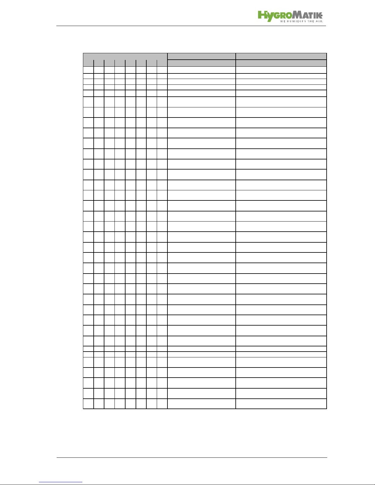
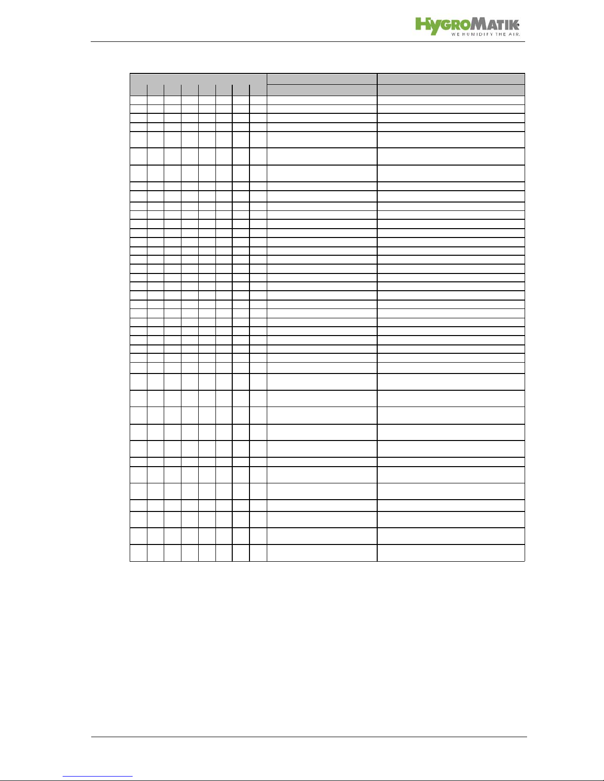
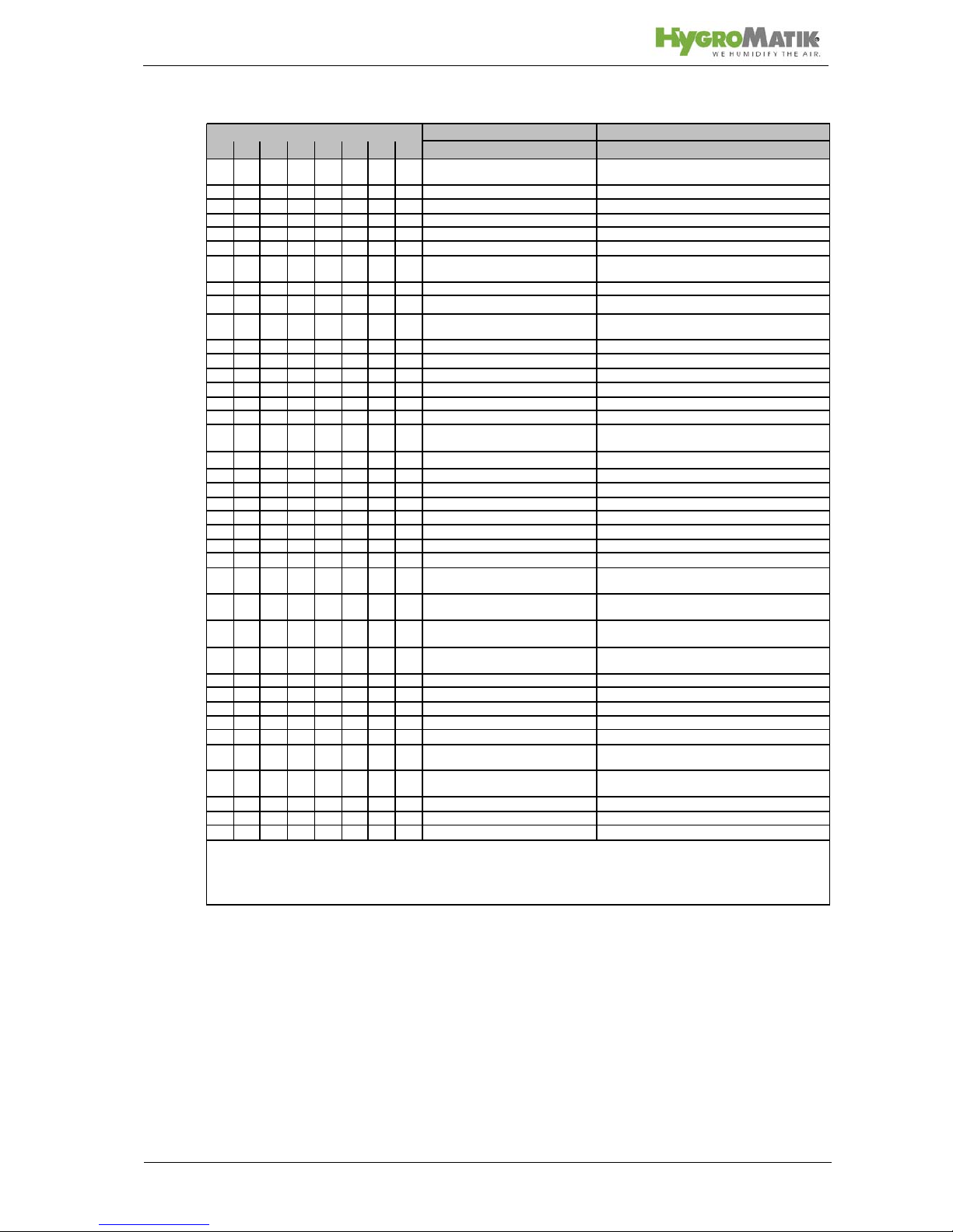
9. Spare Parts
CompactLin e KIT
Description
* 01020610173045
Article No.
Bracket
1 1 1 1 E-2101014
Steam section retaining bracket
1 1 E-210701 2 Steam section retaining brac ket
1 E-2107016 St eam section retaining bracket
Steam Generation
1 B-3216131
Steam cylinder CY1 compl. w i th electrodes and
Hand nuts
1 B-3204049
Steam cylinder CY2 compl. w i th electrodes and
Hand nuts
1 B-3216067
Steam cylinder CY4 compl. w i th electrodes and
Hand nuts
1 B-3204031
Steam cylinder CY8 compl. w i th electrodes and
Hand nuts
1 B-2204101
Steam cylinder CY17 compl. with electrodes and
Hand nuts
1 B-2204111
Steam cylinder CY17 DN40 com pl . wit h
el ectrodes and Hand nuts
1 B-2204105
Steam cylinder CY30 compl. with electrodes and
Hand nuts
16 1 E-3216004 T op part of steam cylinder CY1 DN 20 /9, empty
16 1 E-3216006
Top part of steam cylinder CY2 DN 20 /9, empty
16 1 E-3216043
Top part of steam cylinder CY4 DN 20 /9, empty
16 1 E-3226005 T op part of steam cylinder CY8 DN 25 /12, e m pty
16 1 E-2206068
Top part of steam cylinder CY17 DN 2 5/12, empty
16 1 E-2206082
Top part of steam cylinder CY17 DN 4 0/12, empty
16 1 E-2206069 T op part of steam cylinder CY30 DN 40/12, empty
19 1 B-3216005
Lo wer part of steam cylinder compl. with strainer
19 1 1 B-3216007
Lo wer part of steam cylinder compl. with strainer
19 1 B-3216044 Lower part of steam cylinder compl. with strainer
19 1 1 B-2206046
Lo wer part of steam cylinder compl. with strainer
19 1 B-2206071
Lo wer part of steam cylinder compl. with strainer
17 1 E-3216044
O-ring seal for cylinder flange, transparent
cylinder
17 1 1 E-3216010
O-ring seal for cylinder flange, transparent
cylinder
17 1 E-3216046
O-ring seal for cylinder flange, transparent
cylinder
17 1 1 E-2206050
O-ring seal for cylinder flange, transparent
cylinder
17 1 E-2206051
O-ring seal for cylinder flange, transparent
cylinder
35 1 1 1 1 E-3216011
O-ring seal for cylinder base
35 1 1 1 E-2204022 O-ring seal for cylinder base
48 1 1 B-3204041
Ele ctrodes compl. without Hand nuts, set=2pc. for
CY2
48 1 B-3216061
Ele ctrodes compl. without Hand nuts, set=3pc. for
CY4
48 1 B-3204019
Ele ctrodes compl. without Hand nuts, set=3pc. for
CY8
48 1 B-2204081
Ele ctrodes compl. without Hand nuts, set=3pc. for
CY17
48 1 1 B-2204083
Ele ctrodes compl. without Hand nuts, set=6pc. for
CY17/30 DN40
Page 53
Page 53
CompactLine KI T
Description
* 1 2 6 10 17 30 45
Article No.
1 1 B-3204047 Sensor electrode compl. wit hout hand nut
1 B-3204037
Sen sor electrode compl. wit hout hand nut
1 B-320402 7 Sen sor electrode compl. without hand nut
1 1 1 B-2204075
Sen sor electrode compl. wit hout hand nut
8 1 1 1 1 1 1 1 E-3216025
Plu g-in contact with insulating hose for
sensorelectrode
4 1 2 3 3 E-3216024
Plu g-in contact with insulating hose for steam
ge nerating electrodes
4 3 6 6 E-2206059
Plu g-in contact with insulating hose for steam
ge nerating electrodes
18 8 12 12 12 18 18 24 E-3216022
Clamp for flange of transparent cylinder
Steam Generation
37 1 1 1 1 E-3220000
Cylinder base DN 20/12
37 1 1 1 E-2206086
Cylinder base DN 40/15/12
1 1 1 1 1 1 1 B-321602 3 M ountin g set for cylinder base
12 1 1 1 E-3216020
Condensate plug DN 9
12 1 1 1 1 E-2204035 C ondens ate plug DN 12
1 1 1 1 E-3221000 Adapter DN20/25 for steam hose DN25
1 1 1 E-3221002
Ada pter for steam hose DN25
1 1 1 E-220900 4 Adapter for steam hose D N40
2 1 1 1 E-3221004
Clip for adapter DN25
3 1 1 1 E-3216011 O-ring for adapter DN20/25
3 1 1 E-32210 06 O-ring for adapter DN25
3 1 1 E-2204022
O-ring for adapter DN40
1 B-3216075 Maintenance Set ** *
1 B-3216077
Maintenance Set ***
1 B-321607 9
Maintenance Set ***
1 B-2207029 M ainten ance Set ***
1 B-2207031
Maintenance Set ***
1 B-2207033 M ainten ance Set ***
Water feed
2 2 2 2 2 2 2 E-2304015
Hos e clamp d=12 mm for wat erinlet hose
21 0,6 0,6 0,6 0,6 0,6 0,6 0,6 E-2604002
Connec ting hose, s olenoid valve - cy linder base
25 1 1 B-2304081
Solenoid valve, servo controlled, straight type, 0,2
- 10 bar, 1,2 l/min
25 1 1 B-2304083
Solenoid valve, servo controlled, straight type, 0,2
- 10 bar, 2,5 l/min
25 1 1 1 B-2304085
Solenoid valve, servo controlled, straight type, 0,2
- 10 bar, 3,0 l/min
1 1 1 1 1 1 1 B-2304040 Mounting set for solenoid valve
1 1 1 1 1 1 1 E-2304036
Rubber seal solenoid valve - cabinet
1 1 1 1 1 1 1 B-2304024
Threaded inlet fitting for s olenoid valve,
pipe=10mm, complete with
Water drain
1 B-3401027
Water-drain-hose-system (Pos.19,23,24,25,27)
1 1 1 B-2425005
Water-drain-hose-system (Pos.19,23,24,25,27)
1 1 1 B-2425009 Water-drain-hose-system (Pos.19,23,24,25,27)
Page 54
Page 54
CompactLine KI T
Descripti on
* 1 2 6 10 17 30 45
Arti cle No.
31 1 1 1 1 1 1 1 E-3220005 O-ring for adapter pump - drain hose
311111111 E-3220005
O-ring cylinder base - pump
32 1 1 1 1 1 1 1 B-240402 7 D rain pump without mounting set
1111111 E-2404008
Drain pump housing
1111111 E-2404006
O-ring seal for drain pump
1 1 1 1 1 1 1 B-2424014 M ountin g set for drain pump
38 0,3 0,3 0,3 0,4 0,6 0,6 0,6 E-2604004
Hose EPDM (for manual draining)
1
1 1 1 1 1 1 E-2604062
Stopper for hose E-2604010
L-Electronic
1111111 B-3504077
L-El ectronic pcb compl. without mounting holder
1111111 E-2525121
cover for electronic pcb
1 1 1 1 1 1 1 B-2525122 mounting set for cover
1111111 E-2525152
Terminal 2-pole
1 1 1 1 1 1 1 E-2525154 Terminal 3-pole
1 1 1 1 1 1 1 E-2525156 Terminal 4-pole
1111111 E-2525158
Terminal 6-pole
xxx xxxx E-2502412 Control switch, double pole, middle position "0"
Accessories
x
x x x x E-2604012
Steam hose DN25, per m
x x E-2604013 Steam hose DN 40, per m
x
xxxxxx E-2604002
Condensate hose DN 12, per m
x
x x x x E-2404004
Steam hose clamp DN 25
x x E-2604016 Steam hose clamp DN 40
x
xxxxxx E-2304015
Condensate hose clamp
x
xx xxxx E-2604094 double check valve
x
x x x x B-2604025
Steam solenoid valve 0-0,4 bar, compl. for s team
ho se DN 25
x x B-2604040
Steam solenoid valve 0-0.4 bar, compl. for s team
ho se DN 40
x
x x x x E-2604042 Connectors for steam distribution T-piece DN 25
x x E-2604023 Connectors for steam distribution T-piece DN 40
x
xxxxxx E-2604021
Connectors for condensate T-piece DN 12
x B-2208005 Cylinder Star
x B-2208007
Cylinder Star
x B-2208013
Cylinder Star
x B-2208009 Cylinder Star
x
x x x x E-2604030
Elb ows 90° D N 25, stainless steel
x x E-2604036
Elb ows 90° D N 40, stainless steel
x B-3304061 Super Flush
x x B-2304063
Super Flush
x x x B-2304065
Super Flush
If you order any spare parts, please specify type and serial number of the unit.
** If the Super Flush System i s install ed, consider to ord er also a new nozzle (B-230 4079 ) , ple ase.
*** Maintenance kit contains: Electrodes without hand nuts, O-rings for: adapter, cylinder base, cylinder flange, Cylinder flange clamps.
* see Ex ploded View
Page 55
Page 55
10. Fax Form - Order for spare parts
HygroMatik GmbH
Lise-Meitner-Str. 3
24558 Henstedt-Ulzburg
Tel. +4904193/895-0
Order of spare parts
unit type *______________ serial no.* ___________________
commission: ______________ order no.: __________________
date of delivery ____________forwarder _____________ shipment by ___________
delivery address (if different
from invoice address)
__________________________
__________________________
__________________________
__________________________
* Order can only be processed if unit type and unit serial no. are filled in.
quantity article article no.
Fax Form
Please copy, fill in and fax to
Fax.No. +49(0)4193/895-31
company stamp (delivery adress)
date/signature
Page 56
Page 56
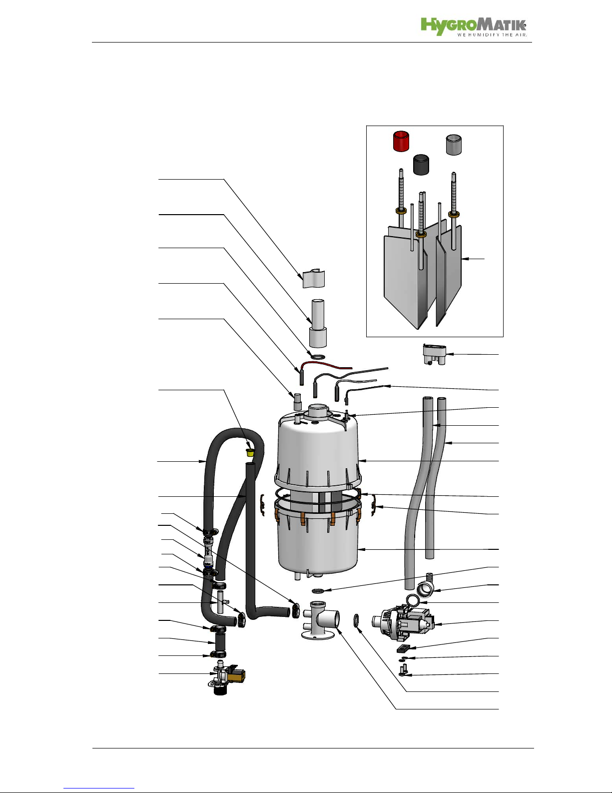
11. Exploded View
30
32
42
1
12
35
31
3
15
38
14
21
20
39
22
37
6
2
16
8
4
18
43
44
17
25
19
31
10
48
22
22
22
24
23
58
22
22
Page 57
Page 57
12. Technical Specification
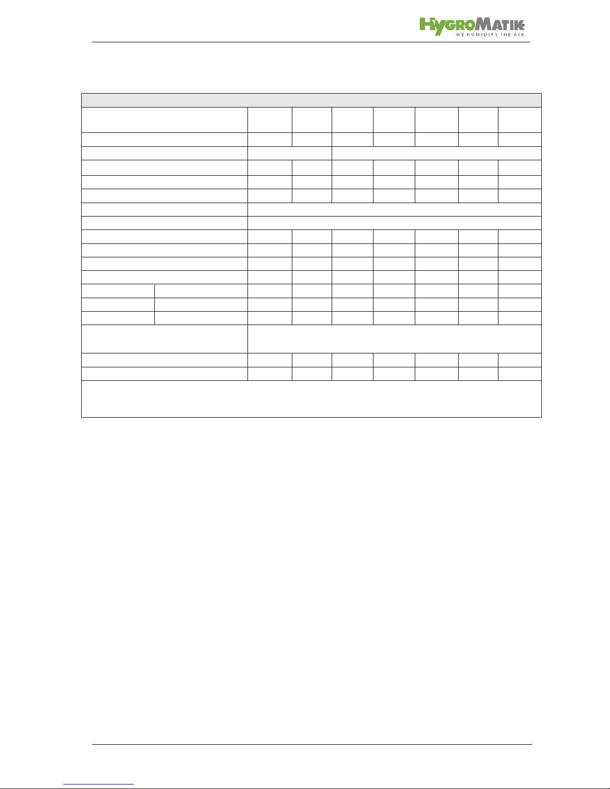
Technical data C01KIT - C45KIT
Type C01
KIT
C02
KIT
C06
KIT
C10
KIT
C17
KIT
C30
KIT
C45
KIT
Steam output [kg/h] 1 2 6 10 17 30 45
Power supply * 230V/1/N 400V/3/N 50-60Hz
Power
Usage [kW] 0,75 1,5 4,5 7,5 12,8 22,5 33,8
Input [A] 3,3 6,5 6,5 10,8 18,4 32,5 48,8
Circuit Protection [A]*** 1x6 1x10 3x10 3x16 3x25 3x35 3x63
Control L3
Control voltage 230 V
Steam hose connection [mm] 1x25 1x25 1x25 1x25 1x25 1x40 1x40
Condensate hose connection [mm] 1x9 1 x9 1x9 1x12 1x12 1x12 2x12
empty weight [kg] 4,5 5 7 8 11 12 15
operating weight [kg] 6 7 12 15 29 30 60
dimensions heigh [mm] 320 300 344 390 575 575 667
width [mm] 252 252 252 252 328 328 330
depth [mm] 175 195 175 175 254 254 316
Water Installation
100 x 10
3
to 100 x 104 pascal with 3/4" connection for external
thread
fan unit** VG08 VG08 VG08 VG08 VG17 VG30 2xVG30
airflow capacity [m³/h] 160 160 160 160 185 350 2x350
* Other voltages on request.
** Not included with delivery.
*** Multiply power input by 1.3 after full blow-down. Note overload capacity of automatic breakers. If necessary, select the next higher rat-
ing.
Page 58
12/2004
Lise-Meitner-Str.3 • D-24558 Henstedt-Ulzburg
Phone +49(0)4193/ 895-0 • Fax -33
eMail [email protected] • www.hygromatik.com
A member of the Group
 Loading...