

Hygena BQ099-586 Instruction manual
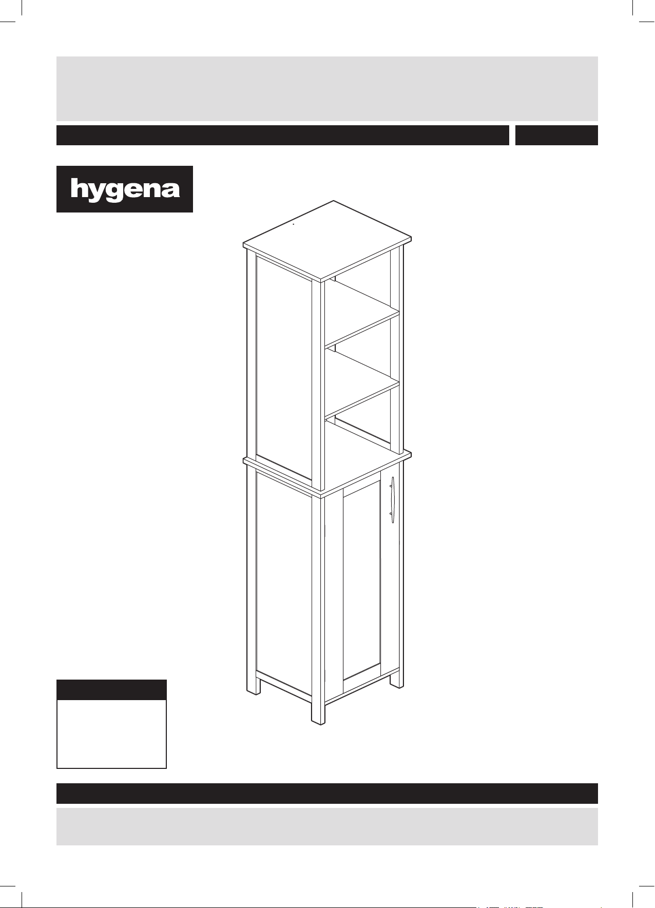
Tallboy
Assembly Instructions- please keep for future reference
833/4448
Dimensions
Width - 35cm
Depth - 30cm
Height - 169.5cm
Important – Please read these instructions fully before starting assembly
If you need help or have damaged or missing parts, call the Customer Helpline: 0845 640 0800
Issue 1 - 26/04/11

Safety and Care Advice
Important – Please read these instructions fully before starting assembly
• Check you have all the
components and tools listed on
pages 1 and 2.
• Remove all ttings from the
plastic bags and separate them
into their groups.
• Keep children and animals
away from the work area, small
parts could choke if swallowed.
• Make sure you have enough
space to layout the parts before
starting.
Care and maintenance
• Only clean using a damp
cloth and mild detergent, do
not use bleach or abrasive
cleaners.
• Do not stand or put weight on
the product, this could cause
damage.
• Assemble the item as close
to its nal position (in the same
room) as possible.
• Assemble on a soft level
surface to avoid damaging the
unit or your oor.
• Parts of the assembly will be
easier with 2 people.
• From time to time check that
there are no loose screws on
this unit.
• We do not
recommend the
use of power
drill/drivers for
inserting screws,
as this could damage the unit.
Only use hand screwdrivers.
• Dispose of all packaging
carefully and responsibly.
• This product should not be
discarded with household
waste. Take to your local
authority waste disposal
centre.
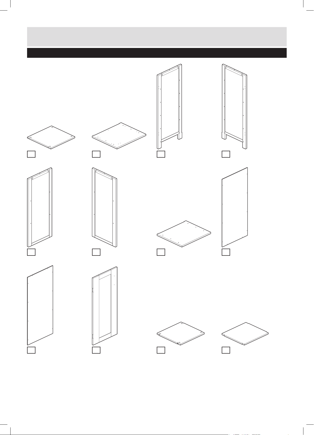
Components - Panels
Please check you have all the panels listed below
Base x 1
1
(29(w)cm x 28.5(d)cm)
Top left side x 1
5
(77.5(h)cm x 28.5(d)cm)
Middle shelf x 1
2
(35(w)cm x 30(d)cm)
Top right side x 1
6
(77.5(h)cm x 28.5(d)cm)
Bottom left side x 1
3
(89(h)cm x 28.5(d)cm)
Top x 1
7
(35(w)cm x 30(d)cm)
Bottom right side x 1
4
(89(h)cm x 28.5(d)cm)
Bottom back panel x 1
8
(80.2(h)cm x 31(w)cm)
Top back panel x 1
9
(79.2(h)cm x 31(w)cm)
Door x 1
10
(78(h)cm x 28.5(w)cm)
Top shelf x 2
11
(30(w)cm x 28(d)cm)
Internal shelf x 2
12
(30(w)cm x 26(d)cm)
1
If you have damaged or missing components,
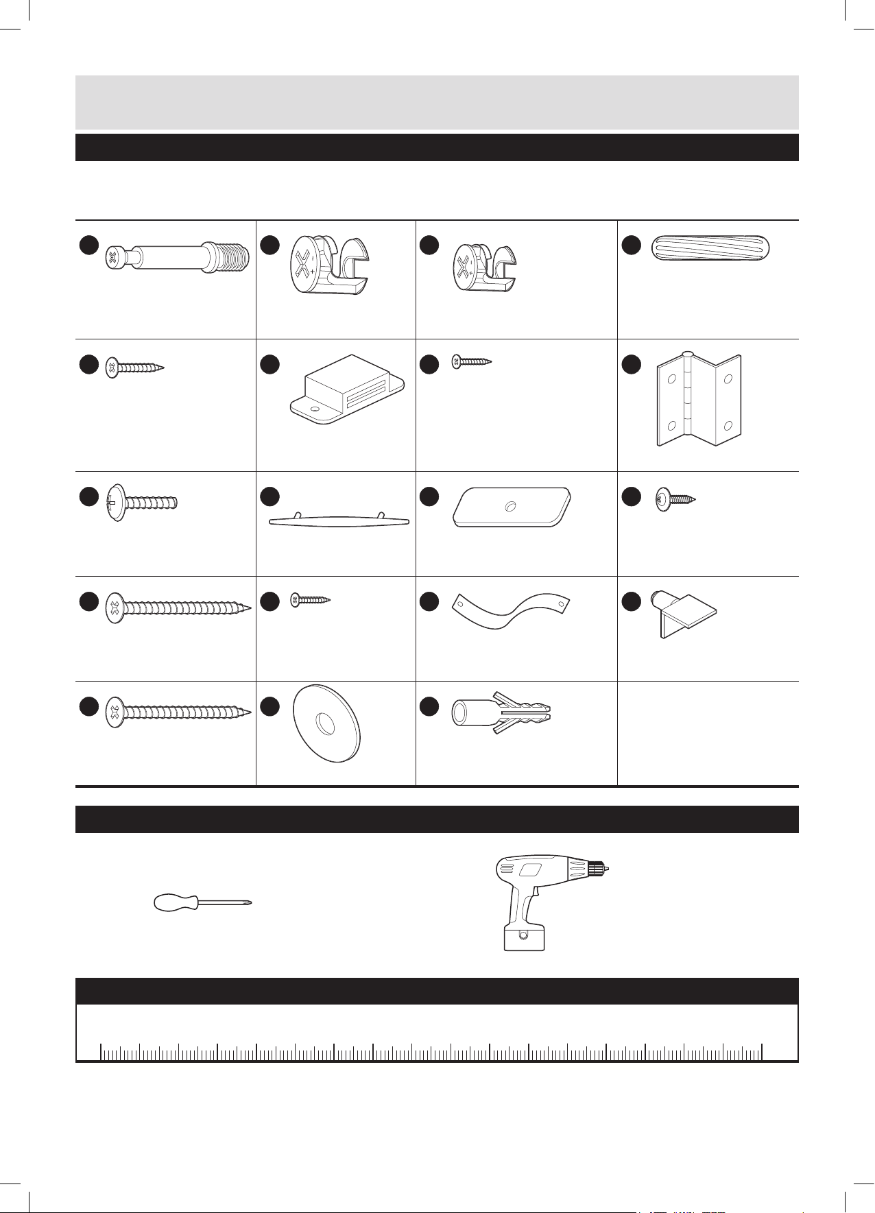
Components - Fittings
call the Customer Helpline: 0845 640 0800
Please check you have all the ttings listed below
Note: The quantities below are the correct amount to complete the assembly. In some cases more ttings
may be supplied than are required.
A
B
C
D
35mm Male camlock x 20 Large female
camlock x 12
E
14mm Screw x 2 Magnetic catch x 1 10mm Screw x 9 Hinge x 2
I
16mm Screw x 2 Handle x 1 Magentic catch plate x 1 Back panel screw x 22
M
F
N
J
Small female camlock x 8 30mm Wooden dowel x 4
G
K
O
H
P
L
35mm Screw x 4 10mm screw x 1 Safety strap x 1 Shelf bracket x 8
Q
35mm Wall screw x 1 Washer x 1 Rawl plug x 1
R
S
Tools required
Phillips screwdriver
(medium & large)
Drill (for wall drilling only)
Ruler – Use this ruler to help correctly identify the screws
105
0 5 10 15 20 25 30 35 40 45 50 55 60 65 70 75 80 85 90 95 100
110 115 120 125 130 135 140 145 150 155 160 165 170
2

Using Camlocks
Step 1
Connect the male
camlock as directed in
the assembly instructions
using a screwdriver.
Step 2
Insert the female
camlock as shown in the
instructions.
Note: ensure that the
arrow on the top of the
camlock points towards
the entry hole for the
male camlock.
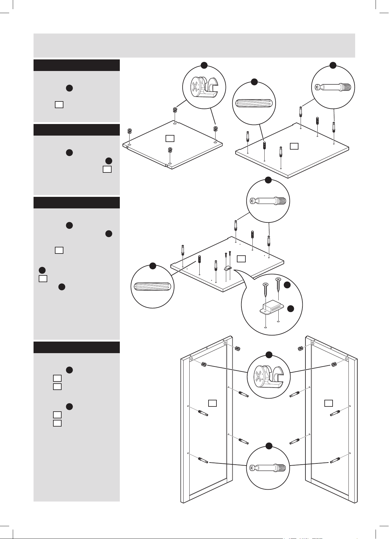
Assembly Instructions
Step 3
Push the male camlock
into the entry hole.
Step 4
Turn the female camlock
clockwise with a
screwdriver.
You should feel a click
when the camlock is
locked in place.
The joint is now secure.
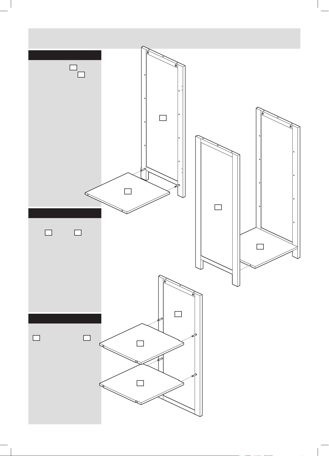
Step 1
Fix 4 x large female
camlock
as shown.
B
into base
Step 2
Insert 2 x large female
camlock
left side
side
Fix 2 x 35mm male
camlock
left side
side
B
into bottom
3
and right
4
as shown.
A
into bottom
3
and right
4
as shown.
B
1
1
B
3
A
4
3
Assembly Instructions
Assembly Instructions
Step 3
Step 3
Screw 2 x male camlock
Fix 4 x small female
A
camlock
into reverse of drawer
front
underside of 2 x top
shelf
C
into
13
as shown.
11
as shown.
Step 4
Fix 4 x 35mm male
camlock
30mm wooden dowel
A
and 2 x
D
into underside of top 7
as shown.
Step 5
Fix 4 x 35mm male
camlock
Step 4
30mm wooden dowel
Connect hinges B to
into underside of middle
top door
shelf
door
Connect magnetic catch
screws
F
to underside of top
7
using 2 x 14mm
screw
A
and 2 x
5
and bottom
2
as shown.
6
using 15mm
F
as shown.
E
as shown (a:).
D
C
D
11
7
A
2
D
E
A
Step 6
Insert 2 x large female
camlock
side
side
Fix 4 x 35mm male male
camlock
Step 5
side
side
Insert 4 x 15mm female
camlock
side of top base
shown.
Insert 4 x small wooden
dowel
9
as shown.
B
into top left
5
and top right
6
as shown.
A
into top left
5
and top right
6
as shown.
E
into under
D
into top shelf
7
as
a:
B
5 6
A
F
4
Assembly Instructions
Assembly Instructions
Step 6
Step 7
Connect top base 7
Connect base 1 to
9
.
4
to top
and top shelf
bottom right side
right side
as shown and tighten
the female camlocks in
Tighten female camlocks
underside of base with
in under side of top base
a screwdriver.
7
with a screwdriver.
2
4
Step 7
Connect top left side
Step 8
to exposed ends of top
base
Connect bottom left
side
Tighten female camlocks
as shown and tighten
in under side of top base
the female camlocks in
underside of base with
a screwdriver.
Set assembly aside until
Step 13.
Screw 4 x male camlock
top
7
and top shelf
9
as shown
3
to base
7
with a screwdriver.
Step 8
A
into the under side of
10
as shown.
1
1
Step 9
Connect 2 x top shelf
11
to top right side 6
Step 9
as shown and tighten
the female camlocks in
Connect top 10 as
underside of shelves
shown.
with a screwdriver.
Tighten female camlocks
with a screwdriver.
1
3
1
6
11
11
5

Assembly Instructions
Step 10
Connect top left side 5
to exposed ends of top
shelves
and tighten the female
camlocks in underside
of shelves with a
screwdriver.
11
as shown
11
Step 11
Fix assembly completed
at Step 10 to middle
shelf
4 x 35mm screw
Note: the male camlocks
and wooden dowels
inserted into middle shelf
pointing downwards.
2
as shown using
2
at Step 5 must be
M
.
5
11
2
M
6
Assembly Instructions
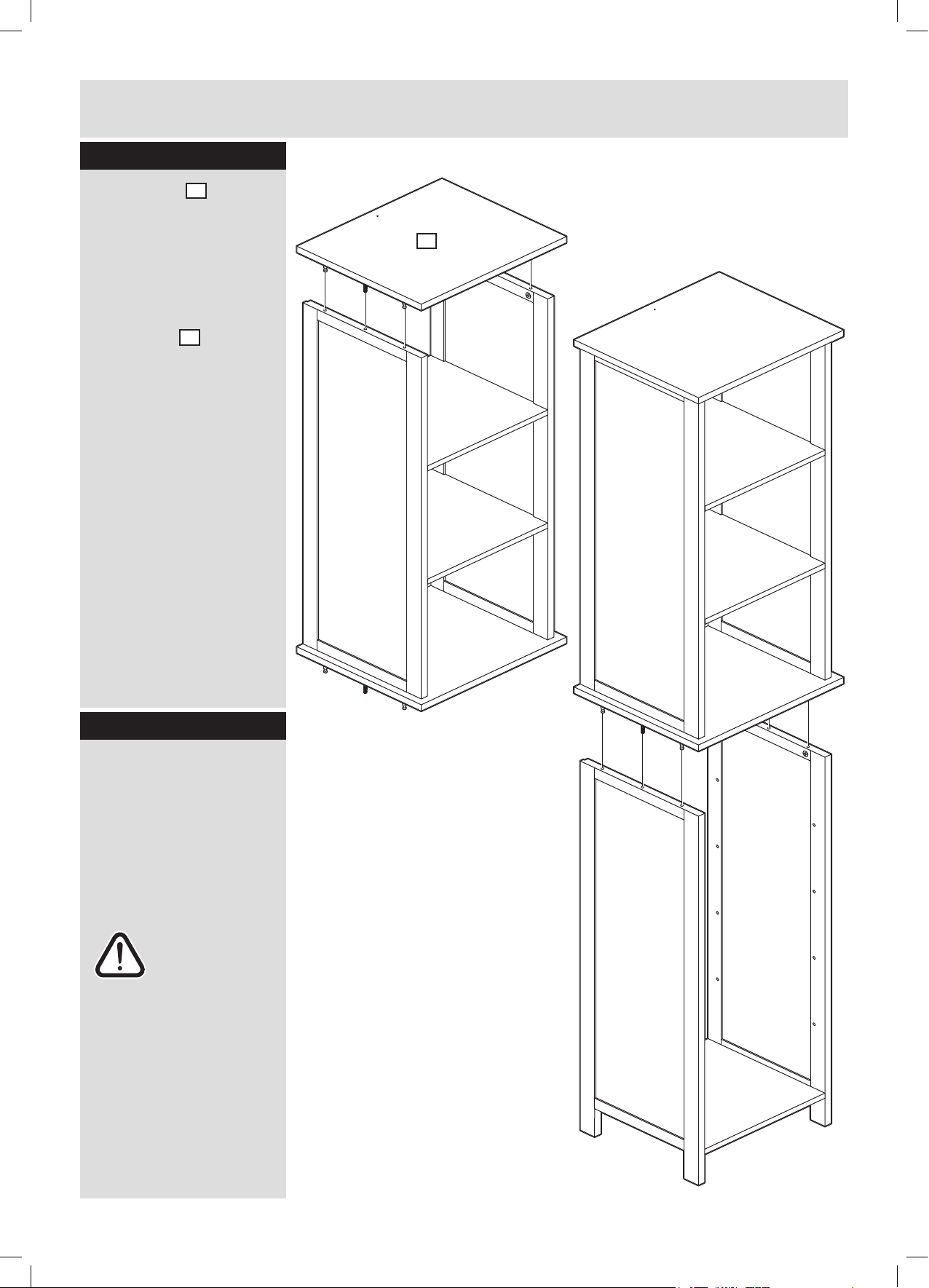
Step 12
Connect top 7 to
assembly completed
at Step 11 as shown.
Tighten the female
camlocks inside the unit
with a screwdriver.
Note: the groove in the
edge of top
pointing to the rear.
7
must be
7
Step 13
Connect assembly
completed at Step 12 to
assembly completed at
Step 8 as shown.
Tighten the female
camlocks inside bottom
left and bottom right
sides with a screwdriver.
Warning: the
unit is heavy.
Ask someone
to help you with
this step.
7
 Loading...