

Page 1
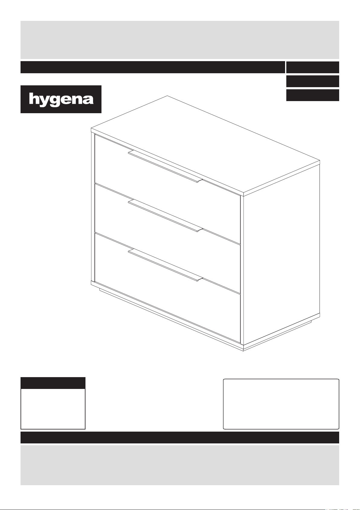
Bergen 3 drawer bedside chest
Assembly Instructions- Please keep for future reference 244/7276
DR825150
228/4532
246/5760
Dimensions
Tip : To prevent damage,
Width - 76.2cm
Depth - 38.1cm
Height - 63.1cm
244/7276 OAK
228/4532 WHT
246/5760 WAL
we recommend that you
build your unit on the
carton(s) it was packed in.
Important – Please read these instructions fully before starting assembly
If you need help or have damaged or missing parts, please visit: www.argos-support.co.uk
or email: Help@ClickSpares.co.uk (quoting your original order number)
Alternatively, call the Spares Helpline on: 0370 112 1928
For any other queries please contact the Customer Helpline on: 0345 640 2020
Issue 3 - 05/11/15
Page 2

Safety and Care Advice
Important – Please read these instructions fully before starting assembly
• Check you have all the
components and tools listed on
pages 2 and 3.
• Remove all fittings from the
plastic bags and separate them
into their groups.
• Keep children and animals
away from the work area, small
parts could choke if swallowed.
• Make sure you have enough
space to layout the parts before
starting.
• Do not stand or put weight on
the product, this could cause
damage.
• Assemble the item as close
to its final position (in the same
room) as possible.
• Assemble on a soft level
surface to avoid damaging the
unit or your floor.
• Parts of the assembly will be
easier with 2 people.
power drill is set on a low torque
setting.
• Dispose of all packaging
carefully and responsibly.
Glue safety - Take care when using glue, please follow the advice below
Skin contact: Remove
contamination by washing with
soap and water. This procedure
should also be followed prior to
eating and drinking.
Eye contact: Rinse immediately
with clean water for 15 minutes
and seek medical advice.
If swallowed: Seek medical
advice immediately.
•To reduce the
likelihood of
damaging your
product please
ensure that your
Care and maintenance
• Only clean using a damp cloth
and mild detergent, do no use
bleach or abrasive cleaners.
Handy Hints
• Assemble all parts and bolts
loosely during assembly, only
once the product is complete
should you fully tighten the bolts
• From time to time check that
there are no loose screws on
this unit.
• Regularly check and ensure
that all bolts and fittings are
tightend properly.
• This product should not be
discarded with household
waste. Take to your local
authority waste disposal centre.
Note: if required the next
page can be cut out and used
as reference throughout the
assembly. Keep this page with
these instructions for future
reference.
2
Page 3
For damaged or missing parts, please visit:
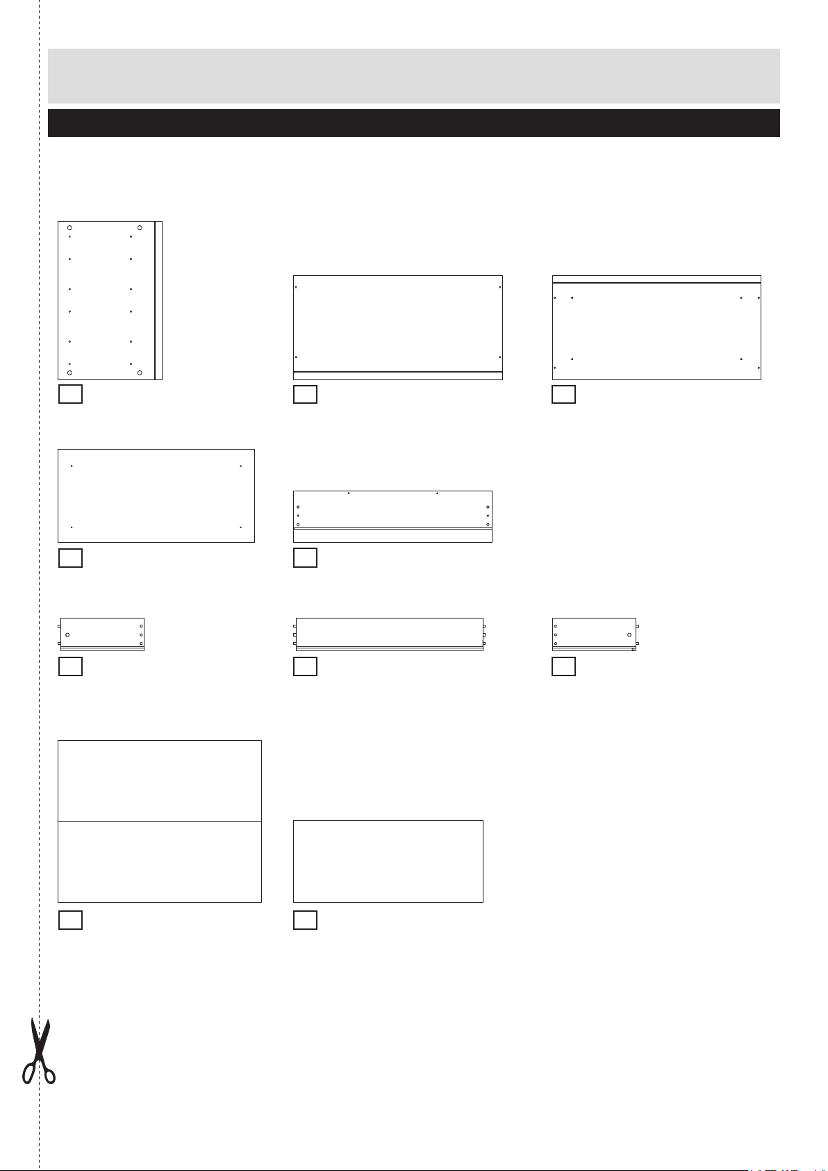
Components - Panels
www.argos-support.co.uk or email: Help@ClickSpares.co.uk
Please check you have all the panels listed below
Left & Right Side x 2
1
(57.9 x 38cm)
P2029
Foot
4
(71.7x 34cm)
P1990
Left Drawer Side x 3
6
(30.5 x 12cm)
LA163109
Top
2
(76.2 x 38.1cm)
P1988
Drawerfront x 3
5
(72.6 x 18.8cm)
FA4234 / P4234
Drawer Back x 3
7
(68.2 x 12cm)
LA162609
Bottom
3
(76.2 x 38.1cm)
P1989
Right Drawer Side x 3
8
(30.5 x 12cm)
LA163209
Foldy Back
9
(59 x 74.2cm)
BO253909
Drawer Base x 3
10
(69.1 x 29.9cm)
BO253709
3
Page 4

105
Components - Fittings
For damaged or missing parts, please visit:
www.argos-support.co.uk or email: Help@ClickSpares.co.uk
Please check you have all the fittings listed below
Note: The quantiti es below are the correct amount to complete the assembly. In some cases more
1/1
FK1012
A
B
15mm
Large locking nut x 8 (15x12mm) Small locking nut x 6 (12x10mm)
D
10mm Fixing screw drawer x 12
G
Felt selfadhesive x 6
J
PM1516LA
Runner left part A x 3
M
PM1516RA
Runner right part A x 3
Locking screw x 14 (5x24mm)
FK1301
E
12,5mm Pozi screw x 51
FK1416
H
Glue x 1
K
Runner left part B x 3
N
Runner right part B x 3
FK1011
FK1309
FA1510
PM1516LB
PM1516RB
C
12mm
F
30mm Chipboard screw x 4
I
Drawerbase support x 28
L
Drawer handle x 3
FK1010
FK1322
FK1250
GR1978
Tools required
Phillips screwdriver
(medium & large)
Flatblade screwdriver
(medium)
Setsquare
Eye protection
(when using a
hammer or drill)
Ruler - Use this ruler to help correctly identify the screws
0 5 10 15 20 25 30 35 40 45 50 55 60 65 70 75 80 85 90 95 100
4
4
The screws length is measured from the head to the point (30mm screw shown).
Small
hammer
0 10 20 30 40 50 60 70 80 90 100 110 120 130 140 150
0 1 2 3 4 5 6
Ruler/tape
measure
Scissors
110 115 120 125 130 135 140 145 150 155 160 165 170
Page 5

Assembly Instructions
C
C
7810J6
C
Step 1
a: Prepare the drawer
fronts
Screw 2 locking screw B
into the holes shown on the
back of each
drawer front 5 .
Note: Insert
locking screw B
as far as shown.
Do not over tighten.
a:
B
3x
5
B
b: Prepare the drawer
sides
Insert a small locking nut C
into the hole on left drawer
side 6 and right
drawerside 8.
Make sure the ‘arrow’ on C
is pointing towards the hole
in the edge of 6 and 8.
Put drop of glue J in the 6
holes of drawersides 6and
8before sliding them onto
the dowels of
drawerback 7.
Slide drawerbase 0 in the
grooves of the drawer-unit.
c: Turn the drawer wrap
assembly over and push onto
the drawer front 5 . Use a
phillips or flatblade
screwdriver, that is a good fit,
to turn 24mm locking nut C
as far as it will go - more than
1/2 turn.
b:
3x
c:
5
3x
5
Page 6

IIIII
I
111
1
DDD
D
AAAAAAA
A
Assembly Instructions
Step 1 continued
finishing the drawers
d: Turn over drawer and
slide drawerbase
supportsI in corner as
shown and fix them, using
the attached screws .
Step 2
Attaching runners
a: Fix runner left and right
side A J and M on left &
right side 1 as shown
using 10mm fixing
screw drawer D and
12,5mm pozi screw E.
d:
3x
a:
J
J
J
M
b: Insert 8 Large locking
nuts A into left & right
side 1 where shown.
Make sure the ‘arrow’
on Ais pointing towards
the hole in the edge of 1.
E
b:
M
M
E
E
J
M
E
E
E
6
Page 7

Assembly Instructions
B3BBB
B
3
3
FFF
F
1
1
AAA
A
Step 3
Attach bottom and foot
Position bottom 3 onto
foot 4 and fix with 30mm
chipboard screw F.
Screw 24mm locking
screws B into bottom 3 .
Note: Insert locking
screw B as far as shown.
Do not over tighten.
4
Finished
front edge
Step 4
Attaching left & right side
Position left & right side 1
onto bottom 3.
Use a screwdriver to turn
locking nuts A clockwise
to lock.
M
A
7
Page 8

911
2
Assembly Instructions
Step 5
Slide in foldy back
Slide foldy back 9
into the grooves in left &
right side 1 .
Step 6
a: Prepare top
Screw 4 locking screw B
into the holes shown on top
2 .
Note: Insert locking screw
Bas far as shown.
Do not over tighten.
B
B
B
B
8
Page 9

211
AAAAIIIIIIIIIIGGGGG
G
4
9
Assembly Instructions
Step 6 continued
b: Attaching top
Position top 2 onto left &
right side 1 .
Use a screwdriver to turn
locking nuts A clockwise
to lock.
M
A
Step 7
Fixate foldy back
Turn over chest and slide
drawerbase supportsI in
corner as shown and fix
them, using the attached
screws .
Stick the selfadhesive feltG
strategically underneath
the foot 4.
Important:
Chest MUST
be ‘square’
when back is
attached.
9
Page 10

KNEEEEE
E
6
8
LEE
E
5
Assembly Instructions
E
E
Step 8
Attaching runners
Fix runner left and right side
B K and N on left & right
drawer side 6 and 8 as
shown using 12,5mm pozi
screw E.
Step 9
3x
Attaching drawer handle
Attacht drawer handle L on
drawer front 5 as shown
using 12,5mm pozi screw E.
Step 10
Inserting drawers
3x
10
 Loading...