

Page 1
How
to
get
the
most
from your
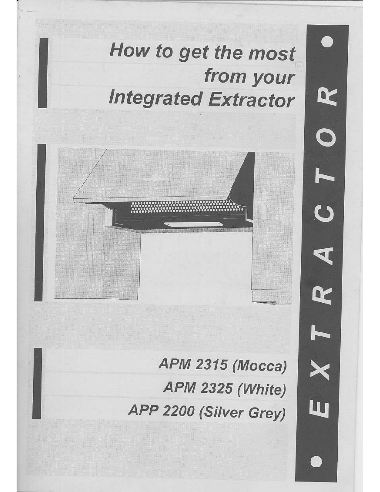
Integrated
Extractor
APM
2315
(Mocca)
A:PM
2325
(White)
APP
2200
(Sitver
Grey)
Page 2
Contents
.1
PagetNo.
o
1
Contents
.2,3
&
.5
.6
.7
.8
o9
o10
o
11
4 Extraction Without lntrusion
Safety & Cleaning
Alternative Methods Of Extraction
Operation
Fitting Charcoal
Filter / Bulb Replacement
Electrical Connections
Not Working Properly?
12 Months Guarantee
Page 3

.
Extraction
Without lntrusion o2
The elcractor is designed to
give you
the option to enract air by ducting to the oltside
and away
(via
an exterior
wall), orto re-circulate airthrough specially designed
filters to
minimize odours, steam and
condensation.
The choice is
yours
to
decide ai installation, and both systems
are explained in this
booklet.
Werecommendthaiyoureadthis
bookletfromcovertocoverbeforeattemptingto
install
ot opetate the
extractor.
.lnstallation
THIS INSTRUCTION
MUST BE STRICTLY ADHERED
TO. FAILUBE TO COMPLY
COULD BESULT IN OVEBHEATING
AND SERIOUS
DAMAGE TO YOUR APPLI.
ANCE.
Theexlractor is designedtofit
perfectly
betlveen two
units, and to occu
py precisely
one
units
width
(600mm).
When
nsialling
your
extractor above a
heat source, i.e., any
electrical
or
gas
hob, cooker
eic., the fixing height must
l,,/Of BE LESS THAN 65cm
between
the hob and the bottom
oi the extractor.
To secure
the
product
to the wall
you
must initially remove the
grille
/
anti-grease
fllters.
This
is achieved by opening the front
panel
and
pushing
the two calches
(A)
upwards
which willthen
release the
grille.
Page 4
Extraction
Without
lntrusion cont..
o3
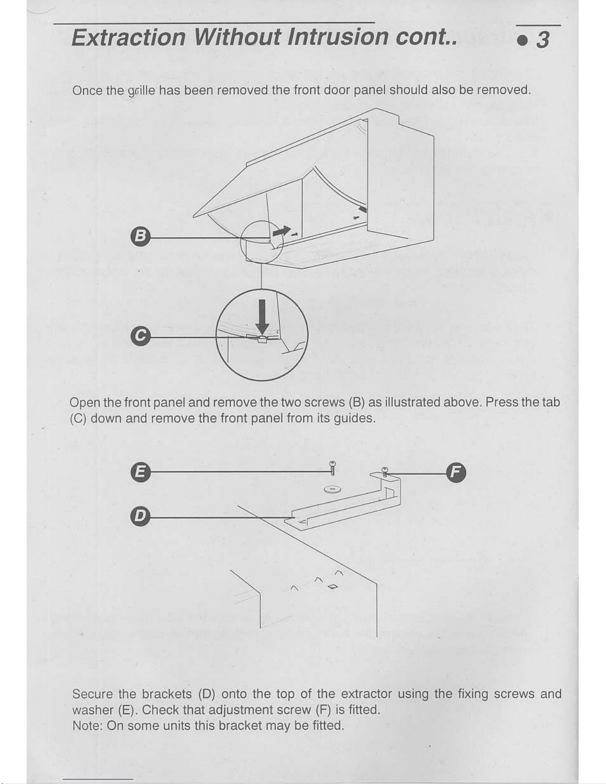
Once
the
gril
e has been remoied the
front door
panel
should also be removed.
Open th e front
panel
and removethetwo
screws
(B)
as illustrated above. Pressthetab
(C)
down and remove the tront
panelfrom
its
guides.
Secure the brackets
(D)
onto the top of the
eruacior
washer
(E).
Check thal adjustment screw
(F)
is fitted.
Note: On some units this bracket may be
fitted.
andusing ihe fixing screws
Page 5

Extraction
Without lntrusion cont..
c4
Ensuring there
is a minimum
distance of 65cm between
the bottom of the exlracior
and hob
surface, then tix the
two mounting brackets
(G)
to the reaf wall.
Once the two
mounting brackets are
in
position
hook the
extractor mounting bracket
tDl
orro
rFe
wall
'nounling
bracket.
Some
adjustmenl is
provided
within the brackets.
For forwald and backward
adjusf
ment
use screw
(E)
and
for heighi alignment adjust
screw
{F).
Once the
adjustment is compleie
fu ly tightening all screws.
if after installation
there is a
gap
between the rear wall and
ihe e)dractor a spaceT
is
provided.
This
can be fixed to the
rear of the extractoT and cut
to accommodate the
gap.
IIIPORTANT NOTE:
After the extractor
has been
Positioned
correctlythe
extrac'
tor
must be fixed tothe
adiacenl cabin ets th
rough the fixing holes in the sides oI
the
extraclor.
All that remains is to tix
the tront wooden door
panel
to the extractoL
By using the diagram
below fix the front
panel.
268rhlh
I
Page 6

.
Electrical Safety
.5
Before
you
think about
fixing, it's as wel to
give
carefu consideration
to the
power
connecuon. lt is vital that the
supply cable should be well shie ded form
your gri
l, hob
or oven. lt it isn t, heat lrom any
one ofthese sources may damage the cab e insulation
and
give
rise to a lire
risk. Under no c rcumstances should the exposed
power
supp
y
cable come wilhin 70cm
oi a direct source oi heal. ldea ly it should be channelled
into
the wall. well out of harm's wav.
o
ForYour SafeV
In order to
protect yoLr
appliance
and mjn m se the risk of flre, dont barbecue food
directly under the
extractor. Similarly, do not
prepare
flambe dishes immediately
under the extractor.
lf
you
use a
gas
hob, do not remove
pots
without first turning
oft the tlame, Your extracior
is designed to draw
gases
up and away from
your
hob.
This means that exposed flames may
behave unprediciably in the vicniiy of the
appl ance while
it is
sw
tched on. When frying take
particular
careto
preventthe
o lfrom
catching
fire and never leave Lrnatrended.
o
Cleaning
IMPORTANT: Beto(e aflempting any c eaning oT
maintenance,
ensure
yo!r
exlractor
is disconnected from the
power
source.
GENERAL CLEANING: Thorough servicing
guarantees
correct and long lasting
operalron.
Wipe the exiefnaL surfaces of the appliance regularly using warm water and a mid
detergent, never use
products
containing abrasive.
Parlicular care
must be
paid
to the
grease
fiter ng
panels
which must be
periodical y
cleaned
in reLation lo use
(at
least once every lwo months).
Benrove
the
grease
fiLiers and wash them using neuiral delergent.
Page 7

Alternative
Methods"
Of
Extraction
o
1. Extraction Via Ducting
(tig.1)
Thevery bestmethod oi cleaning
lhe kitchen of unwanted odours is by conneclingthe
appliance to an exhaust d u ct and venting to th e outside atmosphere via
an e),iterior wal .
(Slitable
dlcting kits may be
purchased
from the store where
you
bought
your
extracto4. Ducting
your
extractor negates the need for charcoalfilters
(fig.1).
tf
DUCTING MODE
RECIBCULATING
MODE
(NO
CHARCOAL FILTEB REOUIRED) (CHARCOAL
FILTEBS REAUIRED)
BEMEMBEB: Belorc
d.
|||_g
or chiseiling rhe wa L chec. for
prpes
and
1. Ensure
the dlcting tube s kept as shori as
possible
and with the minlmum of
bends lo
permit
the smoothest airflow.
(Maximum
length 3 metres).
2. Ducted
air must not be discharged into a flue which
is used for exhausting
fumes from
appliances supplied with energy
other than eiectricity.
3. Ensure
the requirements of the local authorities
are adhered to concerning
the dlscharge
of
exhaust
air.
4. Ensure adequate room
ventilation is
orovided
when
the extractor is used in
the same room as appliances
supplied with energy other
than electricity.
5. Never duct into a hot air
flow such as a centrai heating
duct.
We slrongly advise that
all exterior outlets be fitted wilh
a non rctum
valve ot louvred slatting.
Page 8

.
2. The
Re-circulation
Mode
(fig.2)
a7
When there
is no easy access to
an outside wali, the extractor can
easily be adapted
to clean ajr
polluted
by cooking
smells, by using a charcoal filter
which can be
purchased
from the
slore where
you
bo!ghtyour
extractor under code reference
APM
2906. Rernember
the re-circulation mode
can not be used without a charcoal
filter-
o
The Charcoal
Filter
Filtersdo havealimited life. We advise
yo!
to change it when there is a noticeable
d rop
rn
performance.
The intervals between
chan g ing the filter wlll depend entire
yuponthe
arnount of cooking
you
do, but on
average they will last about 6 months.
o
The
Grease
Filter Mat
The
grease
filter maton modelAPM
2314 reqLrires replacing every 3 months. lfthe
mai
is oi a metallic material it can be cleaned
in a dishwasher or washed with
a neutral
detergent.
Togain accesstothe
greasefilter
mat, the charcoalfilter must be removed.
IMPORTANT:
You should never attempt to usethe extrcctat
without the
greasefilter
since
grease
build-up
could
Nevent
the notor working
prcperly.
lf either fiher is nat
changed
regularlythe risk of fite willbe
increased. Always switch offthe elect city
supply
or
pu
out the
plug
belorc changing
the filterc.
.
Operating
Your Extractor
The motor will automatically operate
by opening and closingthefrontdoor
panelas
long
as the switch is set accordingly.
The extractor fan has three speed settings for either
light, medium or heavyextraction
ofcooking vapours. The ditferent levels
ofextraction
are numbered 1
,2
& 3 and can
be recognised by the changes in noise
leve oi the
extractor
fan when operating.
To switch on the
light simply move the switch to
position
1.
NOTE: The light
is not elfected by apening at closing the
front door
panel.
Neon Indicates
IVlotor
Operation
Levels ol Extraction
o
c-)
Page 9

.
Fifting
Charcoal Filter
o8
To change the Charcoal Filter remove
the flexible wire frame
and simply replace
with
a
1ew
fi'ler as shown
below,
:--a=-.
o
Bulb
Replacement
To replace a bulb
simply remove the
grille
and unscrew
the bulb. Beplace with one
of
the identical type.
Note: The
bulb is not covered by the
guarantee.
Always
swilch oil the electricity sLpply
prior
to changing the bulb.
Page 10

o
Electrical
Connections
o9
TMPORTANT:
ENSURETHATTHE
ELECTRICITY
SUPPLY
lS SWTCHED OFF
BEFORE
CONNECTING.
Your
appliance musl
be connected
to fixed wiring viathe use
of a double
pale
switched
iused spur oullet
wilh at least
3mm contact separaiion,
and
preferably
with a
pilot
lamp.
(See
technical
data for luse
rating). We strongly
recommend
the appliance is con-
nected bv a oualified
electrician
who is a member
ol the N l.C.E
l.c or Corgi who
will
comply with
the l.E.E and any
local regulations.
NOTE:
The
lerminology "DOUBLE
POLE' means
that both
the live and
neutralsupplies
are
switched
and disconnected
at the same
iime.
The
terminations labelled
SUPPLY are
for
the connection
forthe
internal house
wiring
and
the terminations
labelled LOAD are
for
60nnection
for the appliance.
IMPORTANT
The
wires in this
mains lead are coloured
in
accordance
with the
following code:Blue
Brown
Live
Asthe
coloursofthe
wires in the mains
lead
of
ihis appliance may
not correspond
with
the coloured
markings
identifying the
termi-
nals
in
your
spur box,
proceed
as follows;
The
wire whi6h is
coloured blue
must be
connected
to the
terminal which
is marked
with the letter'N'
or coloured black.
Thewire
which is coloured
brown must
be connected
totheterminalwhich
is markedwith
lhe letter
'L'
or coloured
red.
WARNINC
This appliance
has such
technical
particu-
lars that
it belongs to Class
2 insulation and
therefore
niether wire should
be connected
lotheterminal
marked
wilh the letterE or
by
the
earth symbol.
'6l[l'
o
TECHNICAL
DATA:
FUSE RATING:
3 AMP
WIRING TO THE
MAINS
The unit does
notcomewith a
plug
as
there are alternative
ways ol con-
necting itto
the mains supply
(which
should be 230
-
240v - 50Hz). lf
you
are in any doubt
about elecirical
con-
neclion consult
a q ualified
electrician.
Page 11

.
Not Working Properly?
o10
Beiore
you
assume the worst, check this
simple fau t finding
guide
to
get
to the root
of the
problem:
A rep acement is
probably
necessary,
but check first that
the bulb
is iirm y screwed in to its holder. lf the filament
is broken, remember that
the ight bulbs are not covered
by our
guatantee,
Flemember
to disconnect
power
supply before remov ng the
bulb.
Check
grease
fjller rnat. lf it hasnt been cleaned recently,
it m
ght
be clogged wlth
grease.
lf filter mat is re ative
y
clean, check
charcoalfiLiefs. Lf this hasn t been repiaced
ior mote than six months,
remove and insert new one s.
As time
goes
by, accumulaied
grease
tends to stf e ihe
charcoa
iiters in
just
the same way as lhe
grease
fiter
mat, thereby redLrcing
the eificiency of both the fan and
the
filter ltself.
lf
you
re using the unil in re-circu ation mode, change
charcoal filter. lt is obv ous
y past
its
prlme.
Check
plug,
socket and
fuses. lf
these are n order and
fau
t
persists,
jt
could be thai an accumulauon of
grease
has lmpalred the efiiciency
of the switch rnechanism. Try
rdpioly
nov ng sw tch on and o'seve'al lrres
11
succeq-
sion to clear
grease
deposit. lffault continues, cal service
agenr.
Check
your
extractor is sw tched on at the malns. Next,
check for an unexpected
power
strike by swilching on
adjacent lights etc.
lf, having consulted the above diagnostic chart
you
are stil
!nable to
remedythe stuation,
pLease
callthe Free-phone
seNice
No. (Back
cove4.
Page 12

o12
Months
Guarantee
c11
.
Procedure
when
reporting
a
fault
'1.
Give
lull name,
address
including
postcode,
homelelephone
number and
business
telephone
number
if approp.iale
2. Quole
sales
receipt
number, make
and
model number
of faulty
appliance
This
product's
reference
is as
iollows:
APM 2315
/ 2325
APP 22OO
3. Give
a summary
of the
Problem
.";:i:i""1:r:i",1:i::,.;:\::..;:$
"x1is:i."$5:i."$i::,";lr::,";lit
.rl
€
o
Technical
Data
PowerSupply:
2301240v-50H2
Raling:
Fuse Rating:
3 amP
Code
Ref etence
i H
D00 3003
I 80w
(APM
2314)
280w
(APM
231 5 | 2325)
Dimensionsl
H380xW600xD270mm
Lights:
Bulbs
40 WatE
x2
it
PRINTID
ON
RECYCLED
PAPI]R
 Loading...