

Page 1
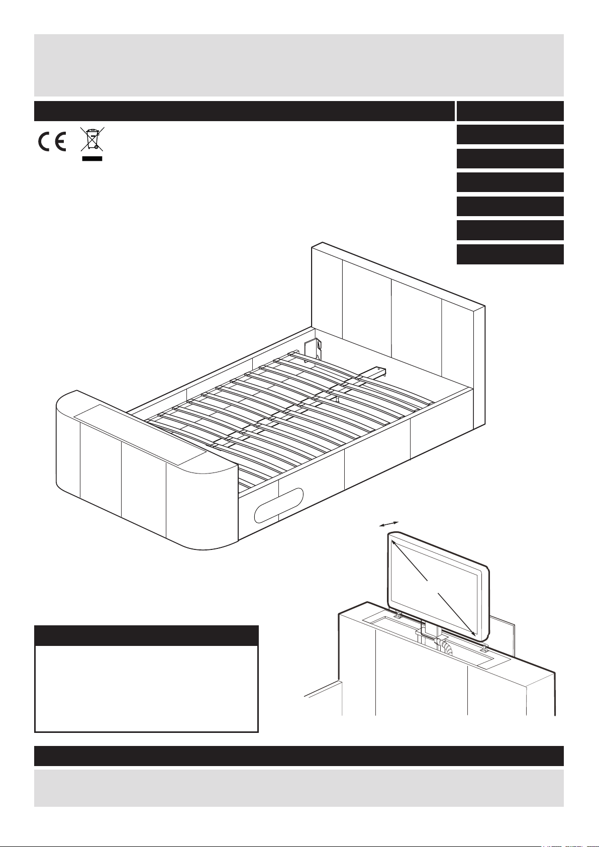
Hollywood TV Bed Frame
Step 7
Assembly Instructions
- Please keep for future reference
656/5075
656/5082
656/8560
656/8577
656/8553
656/8584
656/5099
5cm Max. TV Depth
32inch TV Max.
Dimensions
Width x Depth x Height
228cm x 147cm x 76/102cm (Double)
238cm x 160cm x 76/102cm (King)
236cm x 192cm x 76/102cm (Super King)
Important - Please read these instructions fully before starting assembly
If you need help or have damaged or missing parts, call the Customer Helpline: 01992 450333
Issue 1 - 30/04/10
Page 2

Safety and Care Advice
Important – Please read these instructions fully before starting assembly
• Check you have all the
components and tools listed on
pages 2 and 3.
• Remove all fi ttings from the
plastic bags and separate them
into their groups.
• Keep children and animals
away from the work area, small
parts could choke if swallowed.
• Make sure you have enough
space to layout the parts before
starting.
Care and maintenance
• Only clean using a damp cloth
and mild detergent, do no use
bleach or abrasive cleaners.
• Assemble the item as close
to its fi nal position (in the same
room) as possible.
• Assemble on a soft level
surface to avoid damaging the
unit or your fl oor.
• Assembly requires 2 people.
• Do not fully tighten bolts until
the whole bed is assembled.
Do not overtighten the nuts to
avoid causing damage to the
threads.
• From time to time check that
there are no loose bolts or
screws on this unit.
• We do not
recommend the
use of power
drill/drivers for
inserting bolts
and screws, as this could damage
the unit. Only use hand screwdrivers
and Allen keys.
• Dispose of all packaging
carefully and responsibly.
• This product should not be
discarded with household waste.
Take to your local authority
waste disposal centre.
.
Note: if required the next
page can be cut out and used
as reference throughout the
assembly. Keep this page with
these instructions for future
reference.
1
Page 3
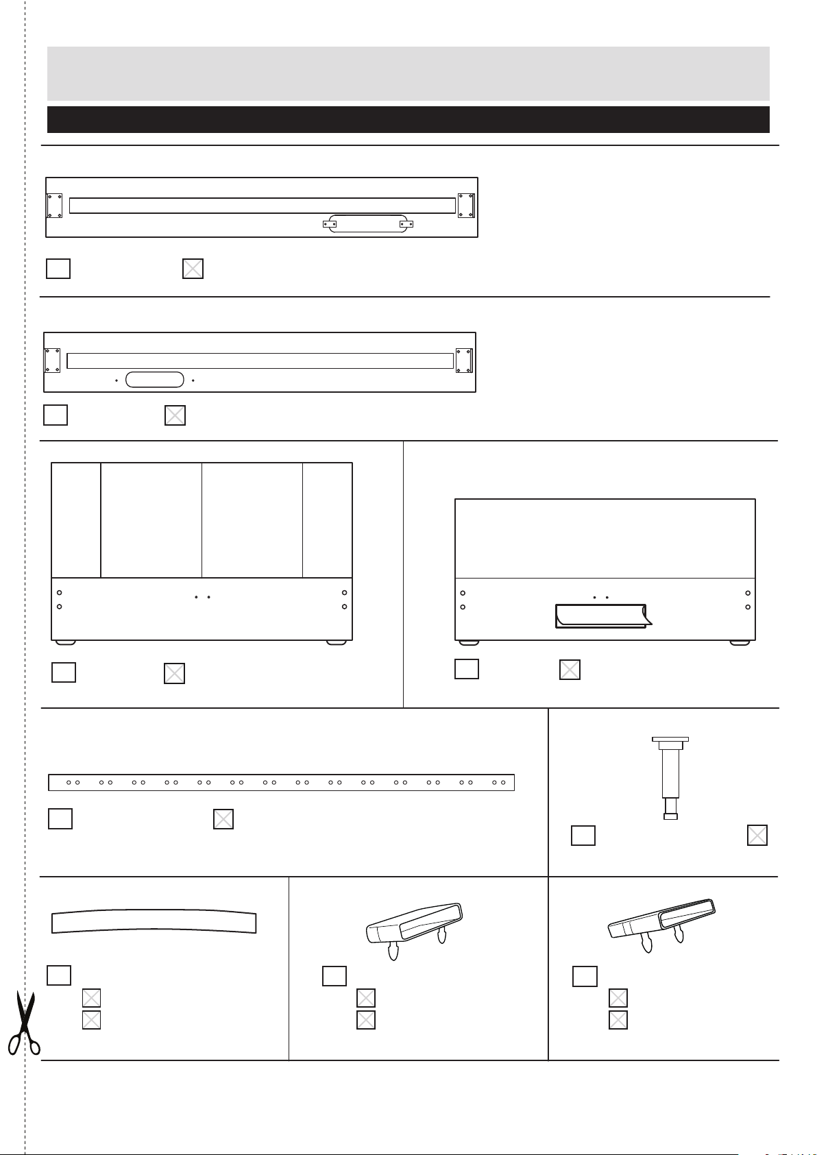
Components
Please check you have all the parts listed below
Headboard end
1 Right side rail
Headboard end
2 Left side rail
If you have damaged or missing components,
call the Customer Helpline: 01992 450333
3 Headboard
5 Central support rail
7
Slats
x 26 (Double)
x 28 (King & S-King)
4 Footboard
8 End slat caps
x 26 (Double)
x 28 (King & S-King)
6 Centre Rail Feet x 2
Central slat caps
9
x 13 (Double)
x 14 (King & S-King)
2
Page 4

Components and Fittings
Please check you have all the parts listed below
10 DVD Tray 12 Cable Tidy
11 DVD Tray Feet x 2
Please check you have all the fittings listed below
Note: The quantities below are the correct amount to complete the assembly. In some cases more fittings
may be supplied than are required.
A
18mm M8 Bolt x 8
D
20mm M8 Bolt x 6
G
B
L-Shaped Bracket x 2 Flat washer (M8) x 12
E
Central Support Bracket x 2
H
C
F
45mm M8 Bolt x 2
30mm M8 Bolt x 4
12mm M6 Bolt x 4
Tools required
Allen key x 1
(supplied)
Phillips Screwdriver
(not supplied)
Ruler - Use this ruler to help correctly identify the screws
105
0 5 10 15 20 25 30 35 40 45 50 55 60 65 70 75 80 85 90 95 100
110 115 120 125 130 135 140 145 150 155 160 165 170
Spanner x 1
(not supplied)
3
Page 5

Assembly Instructions
Step 1
Attaching side rails
a:
Attaching side rails
a:
Loosely attach 2
screws to the
headboard . Hook
over the side rail
onto the bolts then
securely tighten.
Do NOT over tighten
Repeat for opposite
side of headboard
using rail .
Repeat this step for
the footboard b:
A
3
1
3
2
A
A
1
b:
Attaching side rails
Loosely attach 2
screws to the
footboard . Hook
A
4
over the side rail
onto the bolts then
securely tighten.
Do NOT over tighten
Repeat for opposite
side of footboard
using rail .
2
b:
4
1
2
A
A
Note: Ensure that
footboard, headboard
and side rails are square.
Footboard Headboard
4
Page 6

Assembly Instructions
Step 3
DVD Tray Assembly
a: Attach the L-Shaped
Brackets to the underside of the DVD tray
using bolt and washer
C
as shown.
b: Screw the 2 DVD Tray
Feet into position on
the other side of the DVD
Tray .
B
10
D
13
10
a:
b:
10
B
C
D
B
C
D
c: Attach the assembled
DVD Tray to the side
rail of your choice using
bolts and washers
as shown.
Insert the blanking plate
on to the other side rail
where you have not
installed the DVD tray.
10
D
C
C:
10
13
13
C
D
C
10
D
5
Page 7

Assembly Instructions
2
3
5
C
C
E
6
G
G
Step 4
D
Central Support
Assembly
C
Attach the Central Support
Brackets to each end
E
of the Central Support
5
Rail using bolt and
washer .
C
Insert the Feet into
D
6
the holes on the Central
Support Rail and
secure using bolt and
washer .
5
F
C
Step 5
Attach Central Support
E
6
D
6
C
E
C
5
F
C
F
Attach the assembled
central support section
5
to the headboard,
using bolts and
washers as shown.
G
C
Repeat at the footboard
end.
Adjust the feet so
there is a 10mm gap
6
between the floor and
the foot.
3
10mm
from oor
10mm
CAUTION: Do not attempt to move the bed once the centre
support is tted as this could cause damage.
6
Page 8

Fitting the TV
Attaching television
To raise the tv bracket for
tv installation, whilst one
person firmly holds the
handle in position, cut the
two string ties located on
the lower part of the
bracket.
when cutting the ties as
the mechanism will
automatically start to rise
upwards. Carefully raise
the bracket to its highest
position.
You will need a second
person to help hold the
tv. Attach the tv using
four screws as shown.
Take extra care
H
Please contact 01992 450333 or visit www.sleepsecrets.co.uk
for assistance with the mechanism or trouble shooting guides.
H
H
H
H
Please note:
A shock absorber placed
in the last quarter of the
lifting mechanism means
it can be stiff to push
down. This is in place to
protect the television and
prevent damage.
Depending on the size of
tv you install, you may
wish to change the
handle with the longer
replacement handle .
To change handles,
loosen the nuts on the
handle stem located
either side of the bracket
using a spanner. Swap
the handle over, and
retighten the nuts.
14
14
7
Page 9

Fitting the TV
Adjusting television
Should you want to
adjust the position of the
television on the bracket,
remove the television by
unscrewing the four
screws as shown.
H
H
H
H
H
8
Page 10

Adjusting TV Bracket
Should you need to
adjust the position of
the TV bracket to best
t your TV, Follow these
steps:
1. Remove the 4 bolts on
the front plate as shown.
2. Move the bracket up
or down as required.
3. Reattach 4 screws
onto front plate. Attach
television as shown in
previous step.
Remove 4 bolts
from plate.
Adjust height of
brackets
Reattach 4 bolts
to plate.
9
Page 11

VESA TV Bracket
The position of the
mounting holes your
TV use will vary
depending on the
make and model.
The TV bed has
a universal
can accomodate TVs
with the following
standard VESA
compliant sizes.
100mm
200mm
100mm
200mm
100mm
200mm
200mm
400mm
100mm
400mm
10
Page 12

Assembly Instructions
Step 6
Place slats
a:
a: Slot the bed slats
into the end slat caps
and central slat caps
as shown.
b: Attach the slats to the
side rails & and
central support rail by
firmly pushing into place.
1 2
7
8
9
5
8
b:
Step 1
Side rail
support
7
9
7
8
Step 3
Step 2
5
UK Patent Application
No. 1001086.6
The Following EU Design
Registration Numbers
May Apply:
001186100-0001
001186100-0002
001186100-0003
001186100-0004
© 2010 Ventura
Corporation Ltd. All
Rights Reserved.
Side rail
support
Contents may vary to
those shown.
11
Assembly is now complete
 Loading...