

Page 1
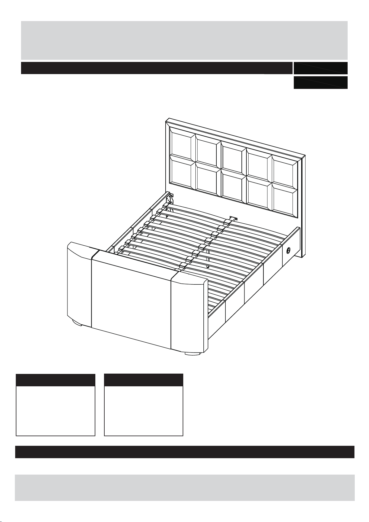
Costello TV Bed
Assembly Instructions - Please keep for future reference
0504/8036
0464/5643
Dimensions (4-6)
Length - 219 cm
Width - 145.5 cm
Height - 115.5 cm
Dimensions (5-0)
Length - 227 cm
Width - 160.5 cm
Height - 115.5 cm
Important - Please read these instructions fully before starting assembly
If you need help or have damaged or missing parts, call one of the Customer Helplines:
0345 6400 800 (For order problems,incorrect product or missing/damaged parts).
01626 879 158 (Only for problems with TV Installation, Electrical System or TV Lift not working).
Issue 1 -09/10/15
Page 2
Safety and Care Advice
Check you have all the
components and tools listed on
pages 2 and 3.
Remove all fittings from the
plastic bags and separate them
into their groups.
Keep children and animals
away from the work area, small
parts could choke if swallowed.
Make sure you have enough
space to layout the parts before
starting.
Only clean using a damp cloth
and mild detergent, do no use
bleach or abrasive cleaners.
Assemble the item as close
to its final position (in the same
room) as possible.
Assemble on a soft level
surface to avoid damaging the
unit or your floor.
Assembly requires 2 people.
Do not fully tighten bolts until
the whole bed is assembled.
Do not over tighten the nuts to
avoid causing damage to the
threads.
From time to time check that
there are no loose screws on
this unit.
We do not
recommend the
use of power
drill/drivers
inserting screws,
as this could damage the unit.
Only use hand screwdrivers and
Allen keys.
Dispose of all packaging
carefully and responsibly.
This product should not be
discarded with household
waste. Take to your local
authority waste disposal centre.
for
1
Page 3
0345 6400 800
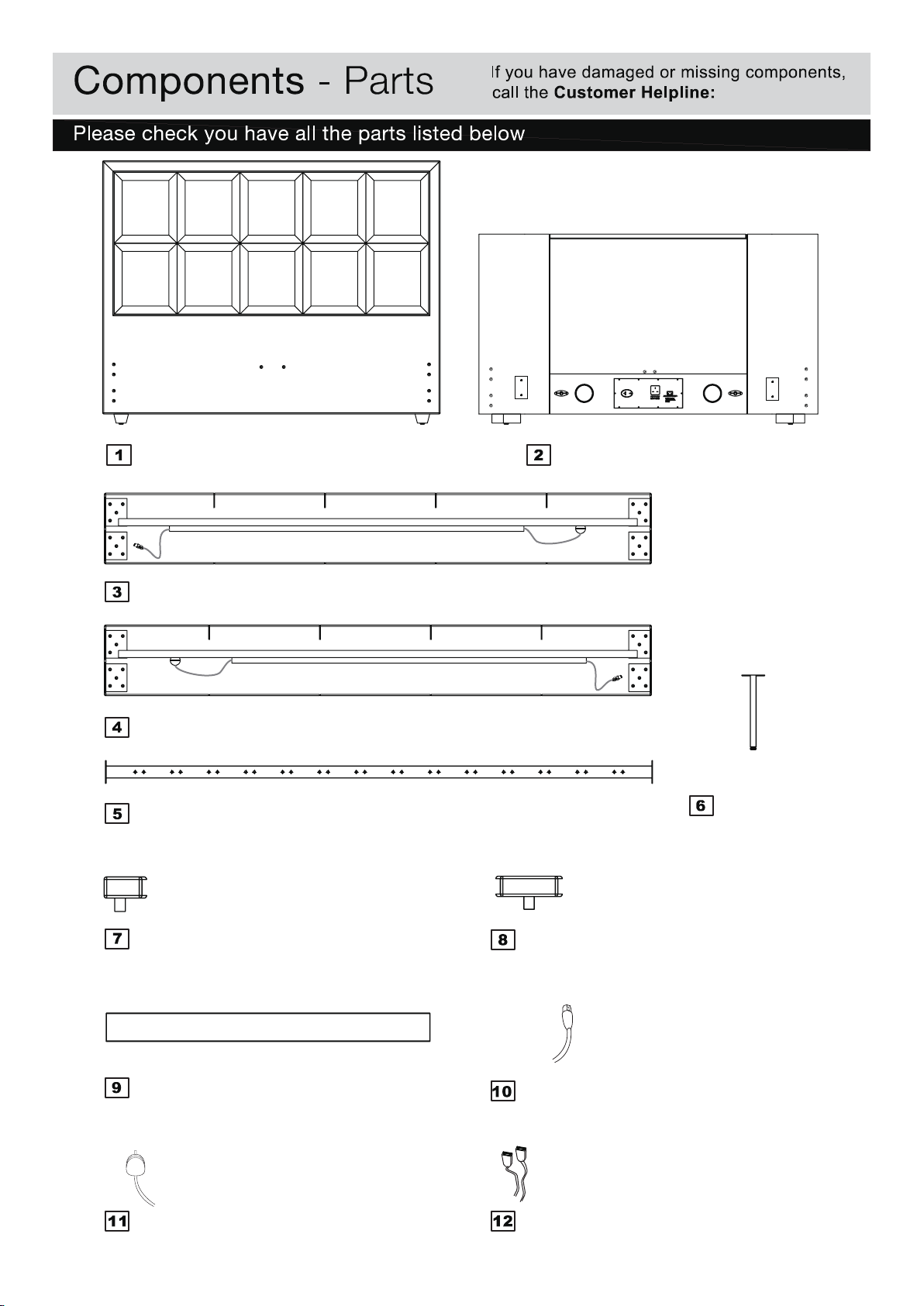
Headboard
Right side rail
Left side rail
Central support
(4-6-1455 × 1155mm)
(5-0 -1605 × 1155mm)
(4-6 -1930 × 350 x 35mm)
(5-0 -2010 × 350 x 35mm)
(4-6 -19
(5-0 -2010 × 350 x 35mm)
30 × 350 x 35mm)
(4-6 -1925 × 40mm)
(5-0 -2005 × 40mm)
Footboard
(4-6 -1455 × 820mm)
(5-0 -1605 × 820mm)
Support
bar legs x2
(263mm)
Single slat caps x 28 (4-6)
Single slat caps x 30 (5-0)
Bentwood slats x 28
Bentwood slats x 30
Mains Power Lead (3 metre)
(4-6 -685x9x53mm)
(5-0 -755x9x53mm)
Double slat caps x 14 (4-6)
Double slat caps x 15 (5-0)
Aerial Lead (4 metre)
HDMI Leads x2 (2.8 metre)
2
Page 4

Components - Fittings
0345 6400 800
A
Allen screw (M8x30mm)
x20 x4
B C
Allen screw (M8x20mm)
D E F
Flat Washer (for M8 screws)
x24
Allen Key (for M8 screws)
x1
G
Cable Tie
TV INSTALLATION KIT
H
Screw-Washer sets (M8x25mm)
x3
x4
J K
Spanner (for 9mm Domed Nut)
x1
Spring Washer (for M8 screws)
F
Cable Clip
Allen Key (5mm)
x3
x1
x16
Counter-Sunk Screws (M6x12mm)
Counter-Sunk Screws (M4x12mm)
x4
x4
M
3mm Self-Adhesive Pads
x12
Allen Key (4mm)
Allen Key (2.5mm)
x1
x1
Tools required
0 5 10 15 20 25 30 35 40 45 50 55 60 65 70 75 80 85 90 95 100 105 110 115 120 125 130 135 140 145 150
0
1 2 3 4 5 6
Ruler/tape
measure
Phillips screw-driver Spanner
Allen key
(supplied)
Ruler - Use this ruler to help correctly identify the screws
0 5 10 15 20 25 30 35 40 45 50 55 60 65 70 75 80 85 90 95 100 105 110 115 120 125 130 135 140 145 150 155 160 165 170
(supplied)
3
Page 5

Assembly Instructions
Assembling Support
Legs
a: Fit support bar legs
to central support
using fixings and .
B
D
E
B
D
D
B
4
Page 6

Assembly Instructions
a: Loosely insert two
screws with spring
washers and flat
washers into each side
of headboard and
footboard and .
Note: Do not tighten fully.
Leave 10mm protruding
as in the diagram.
b:
3 4
and brackets onto
screws , locating the
brackets behind flat
washers .
c: Fit last two screws
spring washers , and
flat washers through
the brackets in the central
set of holes.
A
C
D
Fit the side rails
A
D
A
C
D
a:
10mm
D
C
A
b:
c:
D
C
A
d: Assemble central
support in between
the headboard and
footboard using fixings
and .
A
e: Make sure the bed
frame is straight and
square, as shown in the
diagram.
When all screws are in
place, make sure bed is
still square then tighten
them all 100%.
Carefully adjust the feet
on support bar legs so
there is 5mm gap to the
floor.
D
d:
e:
D
A
A
D
5
Page 7

Assembly Instructions
Electrical & Cable
Connections
a: Connect the Mains
power lead into the 3
Pin socket located on the
right-hand side at bottom
of the footboard .
Connect UK plug to your
wall socket.
Note: the power supply to
this plug must be earthed.
The plug must be easy to
reach if you need to
disconnect the power at
any time.
To operate the TV
Mounting Column
there is a switch in
each side rail of the bed
near the headboard .
W
V
b:
a:
V
TV Mounting Column
Manual Raise & Lower
Buttons.
W
b: The switches are
connected to the TV Lift
control system of the
footboard make sure
they are plugged in
properly align the arrows
on the labels and push
right in.
Clip the wires to the plastic
blocks to keep them tidy.
One can now operate the
TV Lift.
Note: If you press the Up
or Down button in quick
succession (1 Min), the TV
Lift does not move - this
is normal, just press the
button twice.
Keep wires tidy - peel off
pads from clips & adhere
to plastic blocks.
&
DIN plugs
switch (V)
6
Page 8

Assembly Instructions
TV Installation
a: Place TV on Platform
as in sketch. Occasionally
the remote control eye is
mounted underneath the
TV so please make sure it
can be operated correctly.
It may be necessary raise
height of TV by using extra
pads .
M
Note: TV Mounting Column
Max load is 12kg .
W
Max dimensions of TV that
can be fitted: 82x7x4
(WDH)
b: If height adjustment is
necessary - adjust lid-lifter
to maximum height of the
slot using Allen key
loosen the clamping screw
(don’t remove) & slide
curved lifter to top of it’s
slots. Gently lock.
Y
4 cm
K
a:
b:
Y
M
K
TV Mounting Column
W
c: If necessary, adjust
mounting plates by
loosening the four domed
nut and move TV
Z
mounting plates up or
down so bolts are in
line with the VESA fixing
holes on back of TV then
tighten by spanner .
Fix TV with one of screw-
set making sure TV is
H
horizontal then tighten all
four TV screws 100%.
Use Allen Key which
can be found in main
hardware Pack - do not
over-tighten. After final
positioning, adjust lid-lifter
down so curve is slightly
higher than TV - by about
4mm.
X
H
J
K
c:
F
J
Z
X
H
K
7
Page 9

Assembly Instructions
Connect Leads
a: Use cable clip on
F
back of TV to keep leads
tight - make sure all leads
at rear of TV go into the
ducts and cannot get
trapped.
Note: Connect cables
carefully. Use cable ties &
cable clips to keep all
cables tight and as close
to back of TV as possible make sure there is no loose
cable that could become
trapped.
supplied with your TV
Cable Ties
G
4Mt
Aerial Lead
2.8 Mt HDMI
Leads - x2
TV Power Lead.
Cable Clips
FF
b: Pass the TV Power Lead
& Media Leads through the
LEFT or RIGHT duct.
Choose the duct to suit
connections on your TV.
Note: One Aerial Lead
& two HDMI Leads are
supplied. You can also fit
your own media cable as
well but the ducts must be
used to prevent any wires
becomI
ng trapped.
LEFT
DUCT
b:
Aerial Lead
TV Power Lead.
supplied with your TV
RIGHT DUCT
HDMI Leads
8
Page 10

Assembly Instructions
a:
Plug in TV
Note: Power socket for the
TV is not to be used for
any other equipment
because it is not a
permanent supply, it cuts
off power to the TV when
it is down in the starting
position. When TV rises
up, power is then restored.
TV Power Lead
supplied with your
TV
b: Fit bentwood slats
to both sides of double
plastic caps . Locate
single plastic caps to
the ends of bentwood
slats .
Carefully locate the slat
assemblies into position in
between the side rails.
Align the lugs on the
underside of the plastic
caps and tap gently with
a light hammer, until they
are securely engaged.
b:
If you need help or have damaged or missing parts, call the Customer Helpline: 0345 6400 800
Home Retail Group. 489-499 Avebury Boulevard. Saxon Gate West. Central Milton Keynes. MK9 2NW
9
 Loading...