

Page 1

Hygena Genoa Slatted Display Unit
Assembly Instructions - Please keep for future reference 464/2718D
Dimensions
Width - 75cm
Depth - 31.4cm
Height - 152.2cm
Important – Please read these instructions fully before starting assembly
If you need help or have damaged or missing parts, call the Customer Helpline: 03456 400800
Issue 1 - 16/09/15
Page 2
Safety and Care Advice
Important – Please read these instructions fully before starting assembly
• Check you have all the
components and tools listed on
pages 3 & 4.
• Remove all fittings from the
plastic bags and separate them
into their groups.
• Keep children and animals
away from the work area, small
parts could choke if swallowed.
• Make sure you have enough
space to layout the parts before
starting.
Care and maintenance
• Only clean using a damp cloth
and mild detergent, do no use
bleach or abrasive cleaners.
• Do not stand or put weight on
the product, this could cause
damage.
• Assemble the item as close
to its final position (in the same
room) as possible.
• Assemble on a soft level
surface to avoid damaging the
unit or your floor.
• Parts of the assembly will be
easier with 2 people.
• From time to time check that
there are no loose screws on
this unit.
• We do not
recommend the
use of power
drill/drivers for
inserting screws,
as this could damage the unit.
Only use hand screwdrivers.
• Dispose of all packaging
carefully and responsibly.
• This product should not be
discarded with household
waste. Take to your local
authority waste disposal centre.
Note: if require the next
page can be cut out and used
as reference throughout the
assembly. Keep this page with
these instructions for future
reference.
1
Page 3
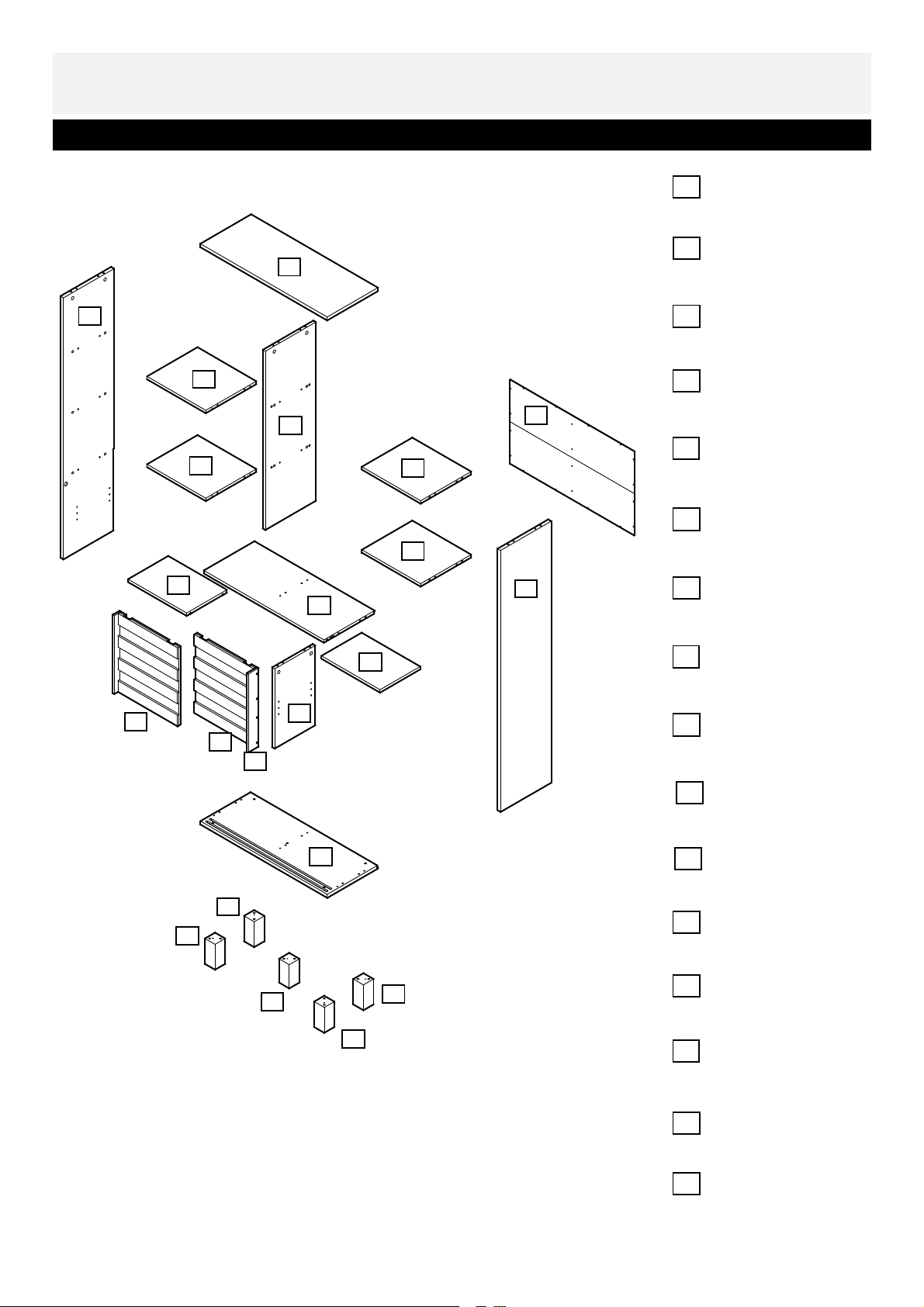
Components - Panels
Please check you have all the panels listed below
3
4
Bottom panel
1
(750 x 300 mm)
Leg x 4
2
(60 x 130 mm)
Top panel
3
(750 x 300mm)
10
14
13
14
8
16
6
9
11
15
15
8
7
5
Left side panel
4
(1340 x 300mm)
Right side panel
5
(1340 x 300mm)
Lower divider
6
(409 x 240mm)
Rear panel
7
(735 x 430mm)
Adjustable shelf x 2
8
(347 x 238mm)
Right side door
9
(351 x 402mm)
Left side door
10
(360 x 402mm)
1
2
2
12
2
2
Right side door rail
11
(402 x 61mm)
Center leg
12
(60 x 122mm)
Upper divider
13
(916 x 299mm)
Left fixed shelf x 2
14
(348 x 299mm)
Right fixed shelf x 2
15
(348 x 299mm)
Lower fixed shelf
16
(711 x 300mm)
2
Page 4
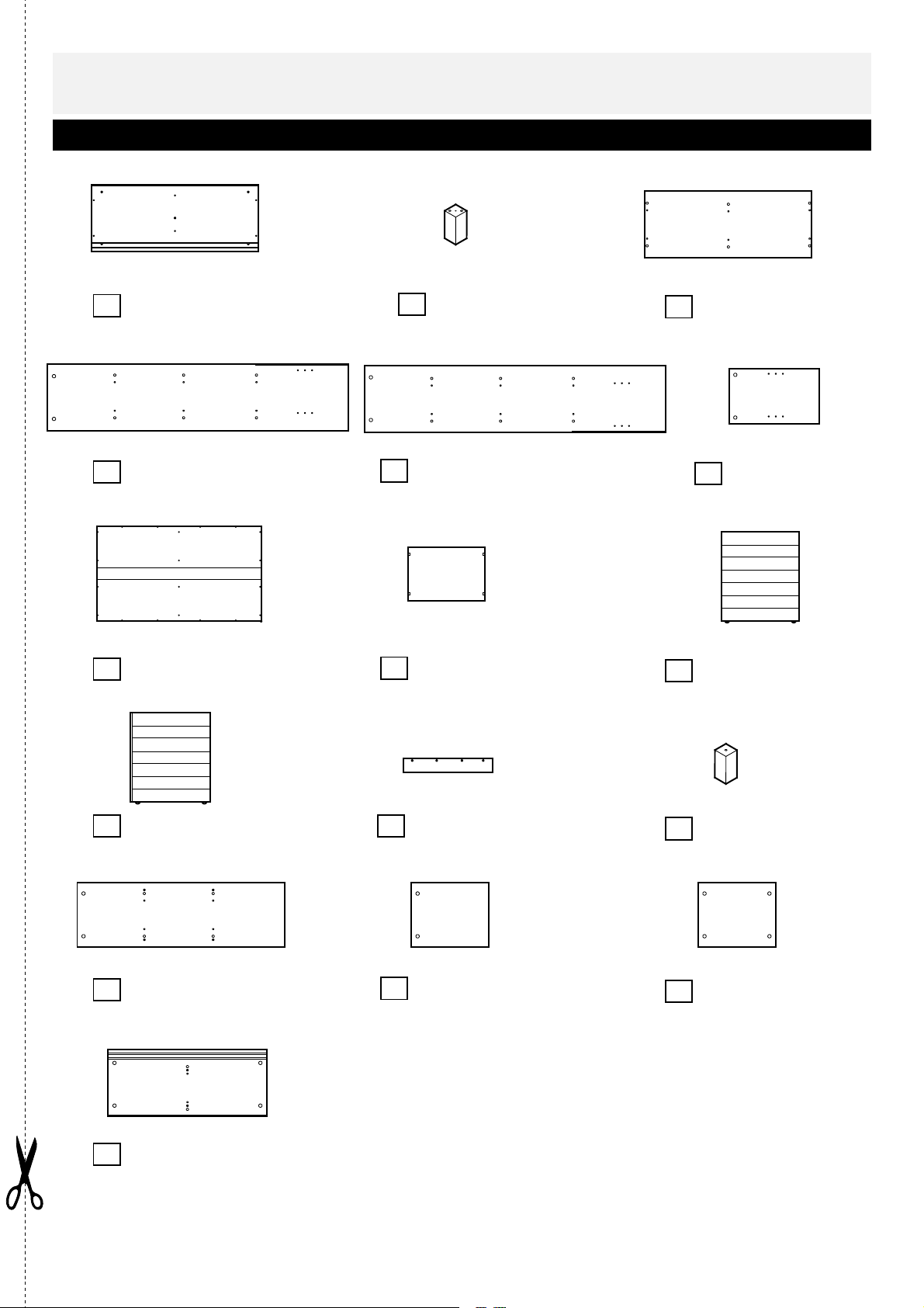
Components - Panels
Please check you have all the panels listed below
Bottom panel
1
(750 x 300 mm)
Left side panel
4
(1340 x 300mm)
Rear panel
7
(735 x 430mm)
Leg x 4
2
(60 x 130 mm) (750 x 300mm)
Right side panel
5
(1340 x 300mm) (409 x 240mm)
Adjustable shelf x 2
8
(347 x 238mm) (351 x 402mm)
Top panel
3
6
Right side door
9
Lower divider
Left side door
10
(360 x 402mm)
Upper divider
13
(916 x 299mm)
Lower fixed shelf
16
(711 x 300mm)
Right side door rail
11
(402 x 61mm)
Left fixed shelf x 2
14
(348 x 299mm) (348 x 299mm)
12
15
Center leg
(60 x 122mm)
Right fixed shelf x 2
3
Page 5
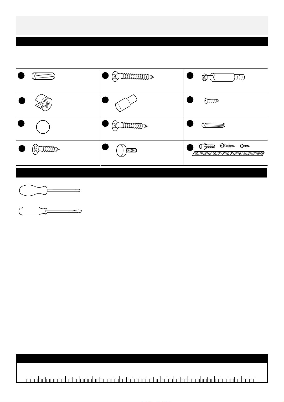
If you have damaged or missing components,
50mm Screw
x
x
A
D
Shelf pin
x
8
110 115 120 125 130 135 140 145 150 155 160 165 170
105
Metal dowel
x
G
J
40mm Screw
x
25mm Screw
K
Webbing and screw x 2
Components - Fittings
call the Customer Helpline: 03456 400800
Please check you have all the fittings listed below
Note: The quantities below are the correct amount to complete the assembly. In some cases more
fittings may be supplied than are required.
B C
Large wood dowel x 10
Metal cam x 24
4
Tools required
E
H I
Adjustable foot
Phillips screwdriver
(medium & small)
Flatblade screwdriver
5
12
24
F
14 mm Screw x 20
Small wood dowel x 36Cover pad x 28
L
Ruler - Use this ruler to help correctly identify the screws
0 5 10 15 20 25 30 35 40 45 50 55 60 65 70 75 80 85 90 95 100
4
Page 6

Assembly Instructions
Step
Step
1
Lay Upper divider and
Left fixed shelves on
13
14
Cam holes underneath
the Left fixed shelves.
their long edges on a flat
soft surface as the
direction shown.
Push Small wood dowels
I I
into indicated holes in
14
the shelves.
14
Push Upper divider
13
onto the wood dowels in
Left fixed shelves and
fasten using 40mm
Screws .
H
Cam holes in the top
right of Upper divider.
13
H
2
Push Wood dowels
into ends of Upper
divider .
13
Push Lower fixed shelf
16
onto the wood dowels
and fasten using 40mm
Screws .
H
I
Cam holes underneath
the Left fixed shelves.
I
16
H
5
Page 7

Assembly Instructions
Step
Step
C
C
3
Screw 6 Metal dowels
into the threaded holes in
Upper divider and Lower
fixed shelf.
13
I
Step 4
Insert Small wood dowels
I
into the center holes
dowels and wood
in Upper divider.
dowels enter
A
Firmly push Right fixed
shelves on to the
Upper divider ,
15
13
ensuring the Metal
dowels and wood
dowels enter
C
I
corresponding holes.
5
Insert the 4 Metal Cams
D
into the 4 holes on
the Panels so that
they are flush.
15
C
16
15
15
D
Note: Longer
leg of the cross
on the Metal
Cams must face towards
end of panel (as shown).
Then, using a Philips
Screwdriver, screw all
Metal Cams
D
clockwise until they are
‘hand tight’.
Note: Longer leg of
the cross on the
Metal Cams must
face towards end
of panel.
D
6
Page 8

Step
Step
Assembly Instructions
C
C
C
6
Screw 6 Metal dowels
into the threaded holes in
Left side panel .
Screw 6 Metal dowels
into the threaded holes in
Right side panel .
4
5
C
4
5
7
Insert Small wood dowels
I
into the middle holes in
dowels and wood
Shelves .
dowels enter
Firmly push the side
panels onto the
ends of the shelves,
ensuring the Metal
dowels and wood
dowels enter
corresponding holes,
secure with Metal cams
D
.
1414151516
A
4
5
C
I
4
16
D
5
Grooves in the rear edge
of side panels for rear panel.
7
Page 9

Assembly Instructions
Step
Step
C
C
C
C
8
Screw 6 Metal dowels
into the threaded holes in
Top Panel as
3
shown.
Step 9
Insert Small wood dowels
I
into the middle holes in
dowels and wood
Side panels and Dividers.
dowels enter
corresponding holes.
Firmly push the Top
Panel onto the ends
of the panels and
13
dowels and wood
dowels enter
corresponding holes,
secure with Metal cams.
A
3
4 5
, ensuring the Metal
I
C
3
Holes in the rear edge for
securing on to the wall in
the last step.
I
3
4
D
13
5
16
10
Insert Small wood dowels
I
into the middle holes in
dowels and wood
Lower fixed shelf .
dowels enter
corresponding h
Firmly push the Lower
divider onto the
A
6
dowels and secure with
Metal cams.
16
I
6
D
Holes in the rear edge for
securing on to the wall in
the last step.
8
Page 10

Step
Step
Assembly Instructions
11
Screw Adjustable foot
K
into the bottom hole of
Center leg . You can
12
adjust the foot to make
sure the unit is stable
when the assembly is
complete.
Step 12
Lay Bottom Panel on
its long edge on a flat
soft surface.
Push Large wood dowels
A
into indicated holes in
Bottom panel.
Push Legs onto the
2
corner wood dowels in
Bottom panels and fasten
using 50mm Screws .
1
B
K
A
12
2
Adjustable foot in
B
1
2
12
the bottom.
2
2
Repeat this step to
secure Center leg in
12
the middle of bottom
panel.
13
Push Wood dowels
into ends of side
panels and .
5
4
Push Bottom panel
onto the wood dowels in
the end of panels and
fasten using 40mm
Screws .
H
Turn the unit upright,
cover all visible cam
holes with Cover pads .
I
6
1
G
I
H
1
4
6
5
9
Page 11

Assembly Instructions
Step
Step
14
Unfold Rear Panel .
Secure the Rear Panel
7
into the rear edges
of side panels, lower fixed
shelf and bottom panel
using 14mm Screws .
Note - make sure
unit is square
before securing
rear panel in place.
Measure on the back
across the 2 diagonals
to make sure unit is
square.
7
F
Tape.
X
Y
F
7
15
Push 4 Shelf Pins
into each side of the
side panels and divider
at desired height.
E
10
Page 12

Step
Step
Assembly Instructions
16
Place adjustable
shelves onto the
Shelf Pins.
8
8
17
Make sure the pin in the
top lock in the Door
is down, if not, push it
down until it locks.
Insert the bottom rollers
of Door in the inner
groove in the bottom
panel, holding the door
and push the top edge to
line up with the inner
groove in lower fixed
shelf.
Push the release button
to release the pin into the
top inner groove.
9
9
Taped edge.
2 people needed for this step.
Pin
9
Release button
11
Page 13

Assembly Instructions
Step
Step
18
Make sure the pin in the
top lock in Left side
10
door is down, if not,
push it down until it locks.
Insert the bottom rollers
of Door in the outer
groove in the bottom
panel, holding the door
and push the top edge
to line up with the outer
groove in lower fixed
shelf.
Push the release button
to release the pin into the
top outer groove.
10
19
Secure Right side door
11
rail on to the Right
side door using
Screws from the
counter sunk hole as
shown.
Cover the visible screw
holes with Cover pads .
9
J
G
11
J
12
Page 14

Step
Assembly Instructions
2 Large Wall Screws
20
Note: This Step
is for securing
the Unit to a
wall and should only be
attempted by
experienced persons.
You will Need the
Following:
- Another person to
assist you
- Electric Drill (& Drill
Bits)
- Screwdriver
Fixings Supplied:
- 2 Webbings
- 2 Small Wood
Screws
-
- 2 Wall Plugs
Note: The
fixings
described are
for use with solid
masonry walls only.
Alternative fixings should
be purchased if you have
a different wall
construction.
Assembly is complete.
If you need help or have damaged or missing parts, call the Customer Help Line: 03456 400800
Home Retail Group plc. Avebury, 489-499 Avebury Boulevard. Milton Keynes. MK9 2NW
13
Page 15

 Loading...