

Page 1
MADE IN
BRITAIN
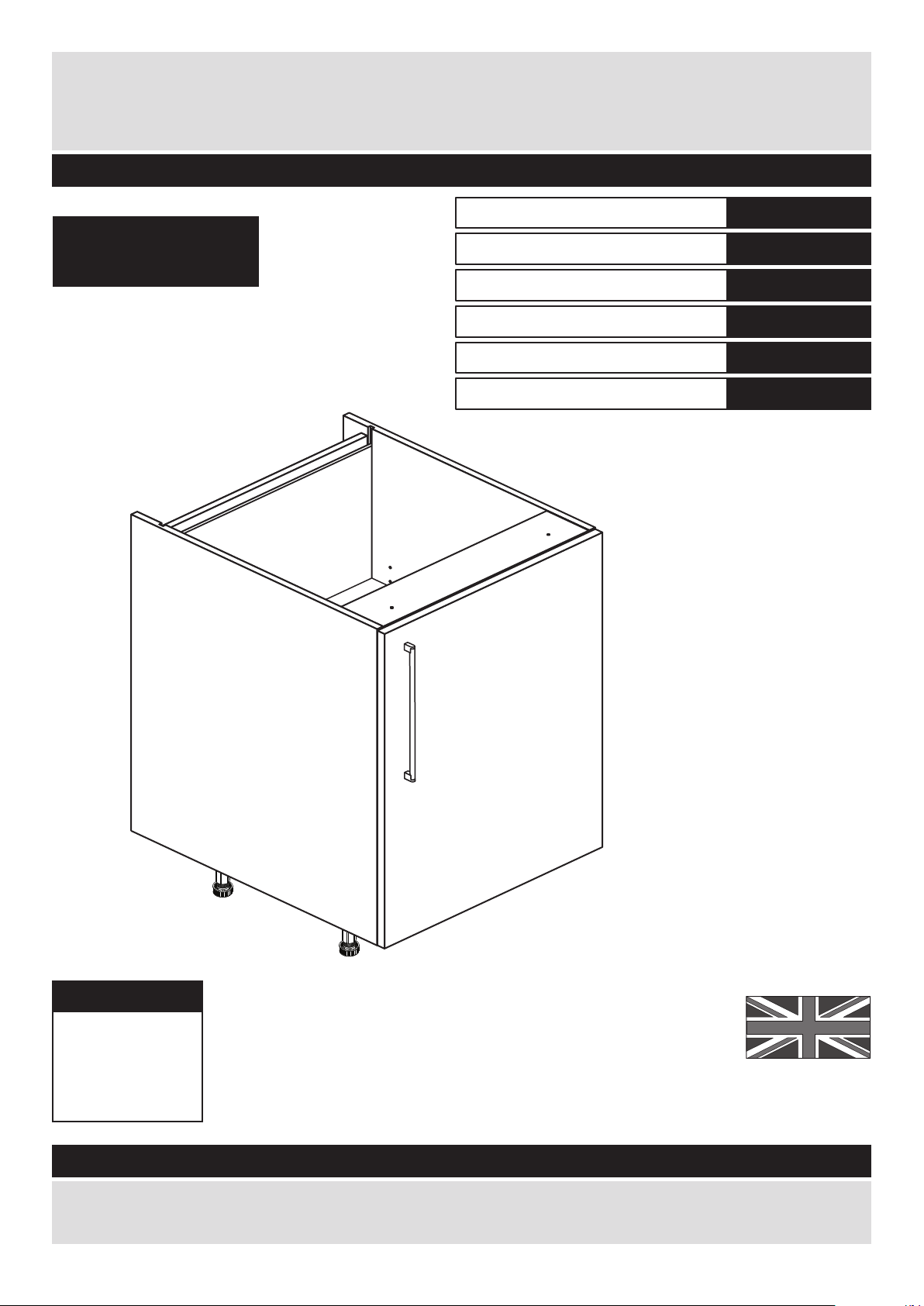
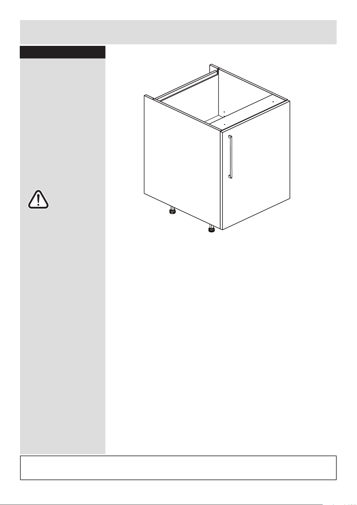
Dimensions
Width - 50cm
Depth - 59cm
Height - 87cm
Valencia - 500mm Base Cabinet
Assembly Instructions - Please keep for future reference
If you need help or have damaged or missing parts, call the Customer Helpline: 08456 400800
Issue 2 - 31/07/14
Important - Please read these instructions fully before starting assembly
hygena
656/5776
633/2882
633/2710
205/4009
633/2806
192/3722
Cabinet
Black Door Pack
Cream Door Pack
Oak Door Pack
White Gloss Door Pack
White HN Door Pack
Page 2

Safety and Care Advice
Important - Please read these instructions fully before starting assembly
• Warning: This unit weighs
approximately 16.5kgs.
Please lift with care.
• Check you have all the
components and tools listed on
pages 1, 2 and 3.
• Remove all fittings from the
plastic bags and separate them
into their groups.
• Keep children and animals
away from the work area, small
parts could choke if swallowed.
• Parts of the assembly will be
easier with 2 people.
• Make sure you have enough
space to layout the parts before
starting.
• Do not stand or put weight on
the product, this could cause
damage.
• Assemble the item as close to
its final position (in the same
room) as possible.
• Assemble on a soft level
surface to avoid damaging the
unit or your floor (use opened
out unit carton).
1
Care and maintenance
• Only clean using a damp cloth
and mild detergent, do no use
bleach or abrasive cleaners.
• From time to time check that
there are no loose screws on
this unit.
• This product should not be
discarded with household
waste. Take to your local
authority waste disposal centre.
Note: If required the next page
can be cut out and used as
reference throughout the
assembly. Keep this page with
these instructions for future
reference.
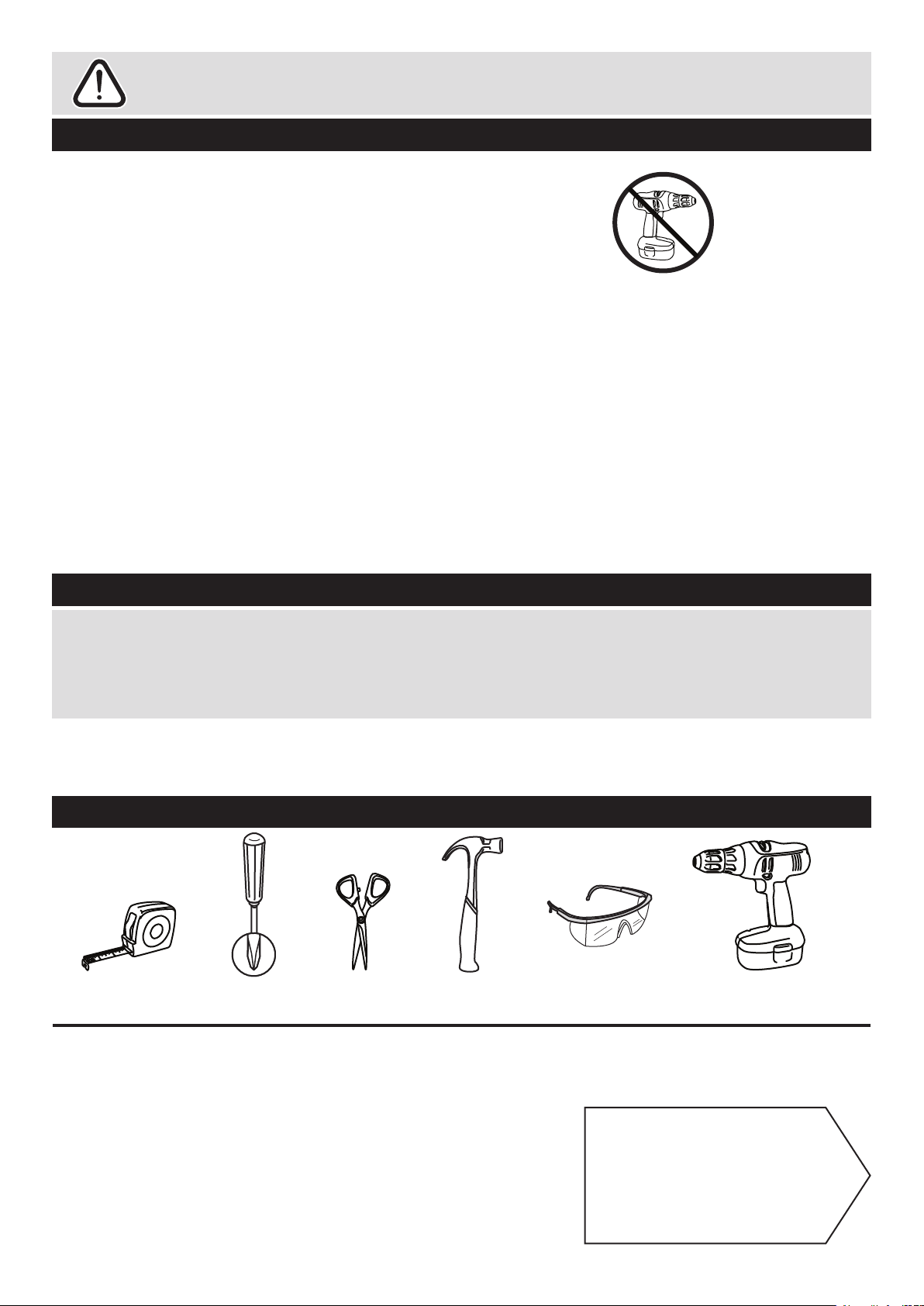
Tools required
Rule Scissors Hammer
Eye protection
(when using a
hammer or drill)
Cross-head
screwdriver
Electric drill
• We do not
recommend the
use of power
drill/drivers for
inserting screws,
as this could damage the unit.
Only use hand screwdrivers.
• Safety note: It is
recommended that this unit is
secured to a wall using the
brackets supplied.
• Dispose of all packaging
carefully and responsibly.
Page 3
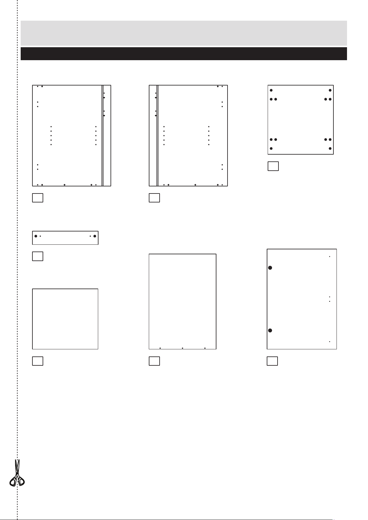
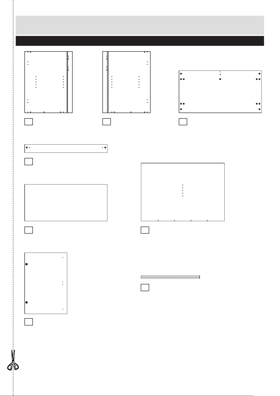
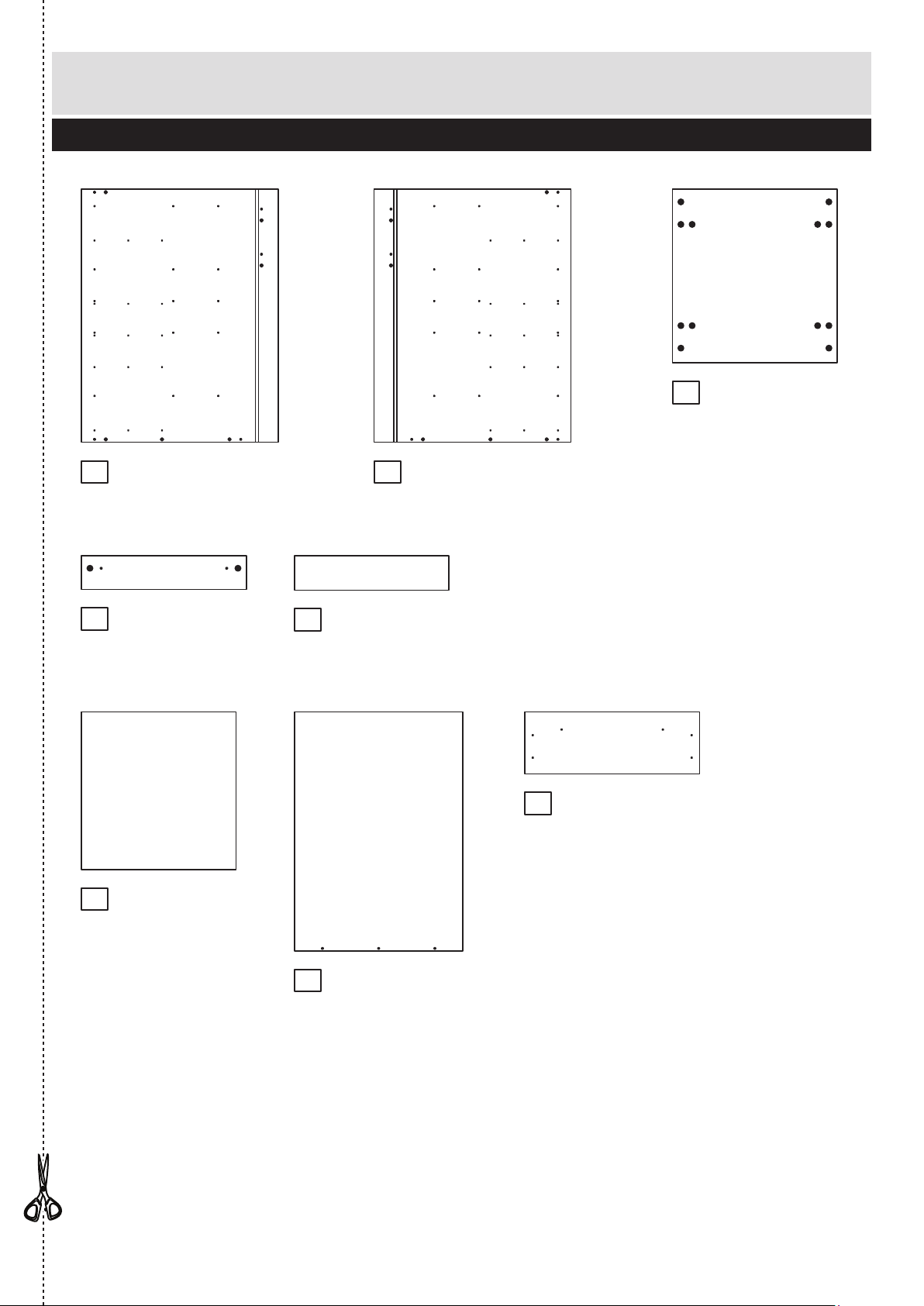
Components - Panels
Please check you have all the panels listed below
2
1
If you have damaged or missing components, call the
Customer Helpline: 08456 400800 quoting the reference
numbers below
5
2
6
4
3
Left Side (DPF068A)
(720 x 560mm)
Right Side (DPF069A)
(720 x 560mm)
Back (DPF077A)
(479 x 680mm)
Loose Shelf (DPF075A)
(468 x 431mm)
Base (DPF074A)
(469 x 494mm)
Cross Rail (DPF076A)
(469 x 96mm) x 2
7
Door (DPF147B)
(497 x 716mm)
The front surface
of this door is
protected with a
peel-off film
Page 4
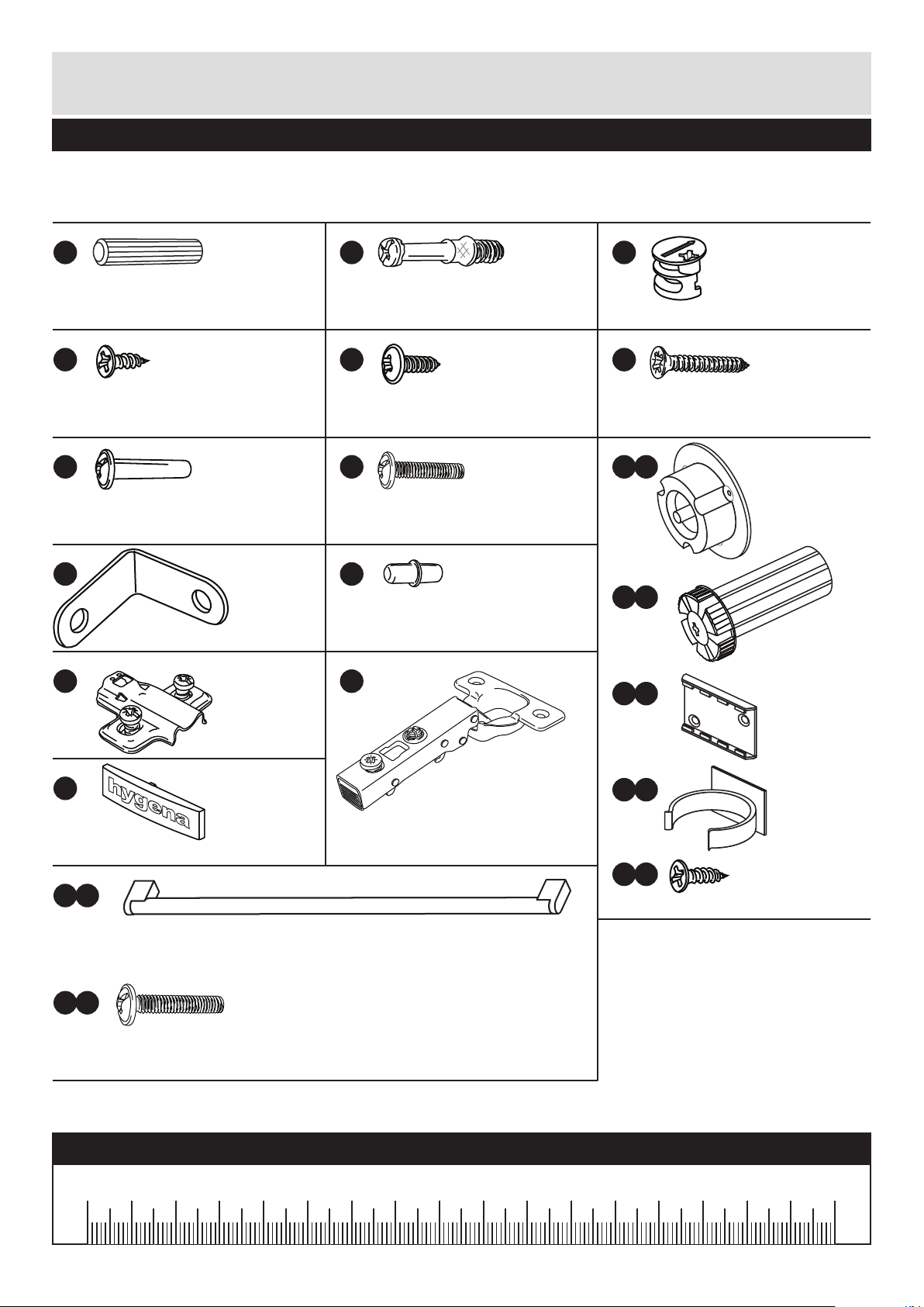
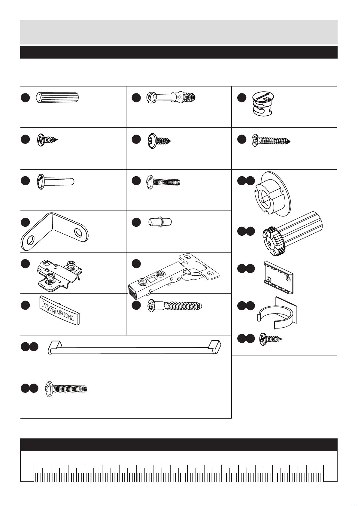
Please check you have all the fittings listed below
3
Components - Fittings
If you have damaged or missing components, call the
Customer Helpline: 08456 400800 quoting the reference
numbers below
Note: The quantities below are the correct amount to complete the assembly. In some cases
more fittings may be supplied than are required.
A
Wooden dowel (F22) x 10
B
Metal dowel (F901) x 8
C
D
Large locking
nut (F900) x 8
F
G H I a
I c
I d
I e
I b
Ruler - Use this ruler to help correctly identify the screws
mm 10 20 30 40 50 60 70 80 90 100 110 120 130 140 150 160 170
J K
13mm Screw (F63) x 4
E
13mm Screw (F79) x 6
Connecting Sleeve (F432) x 2 19mm Connecting bolt (F461) x 2
L M
25mm Screw (F50) x 5
N
Hinge Cover (F119) x 2
Bracket (F945) x 4
Shelf support (F110) x 4
Hinge Plate
(F117) x 2
Hinge Arm (F118) x 2
Leg Bracket
(F127) x 2
Leg Socket
(F120) x 4
Leg Clip
(F128) x 2
16mm Screw
(F129) x 16
Leg (F122) x 4
h
ygen
a
OOa
b
25mm Screw (F132) x 2
Handle (F214) x 1
Page 5
Assembly Instructions
4
If you have damaged or missing components, call the
Customer Helpline: 08456 400800 quoting the reference
numbers below
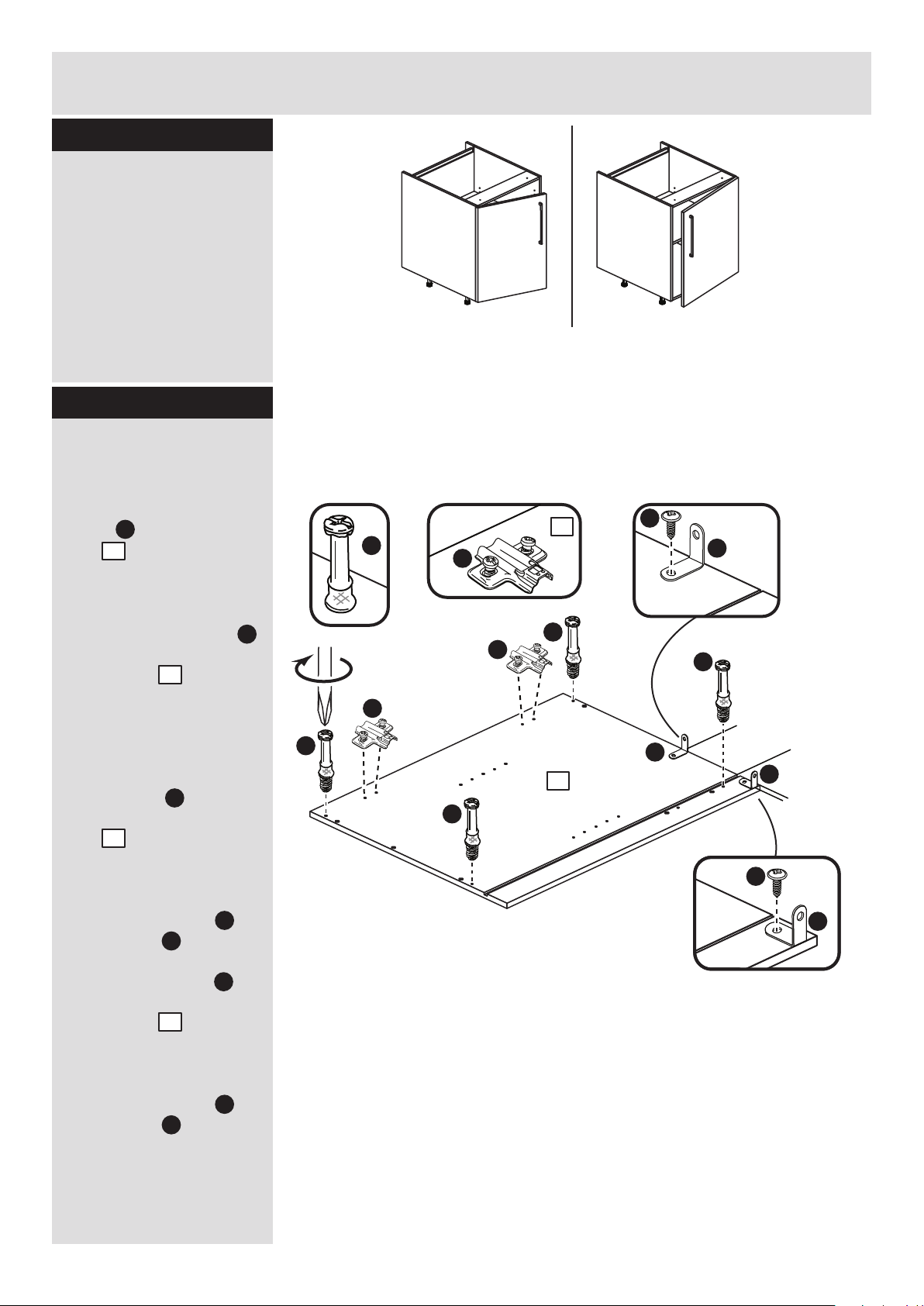
Step 1
Choose which way
you would like the
door to open
You can fit the door to
the left side or right side.
If you would
like your door
to open this
way, fit the
hinge plates
to the left side
If you would
like your door
to open this
way, fit the
hinge plates to
the right side
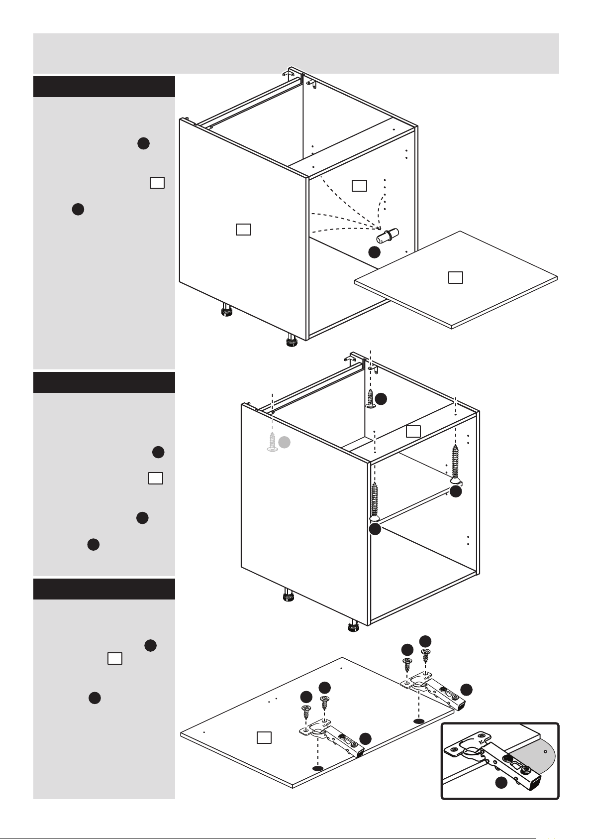
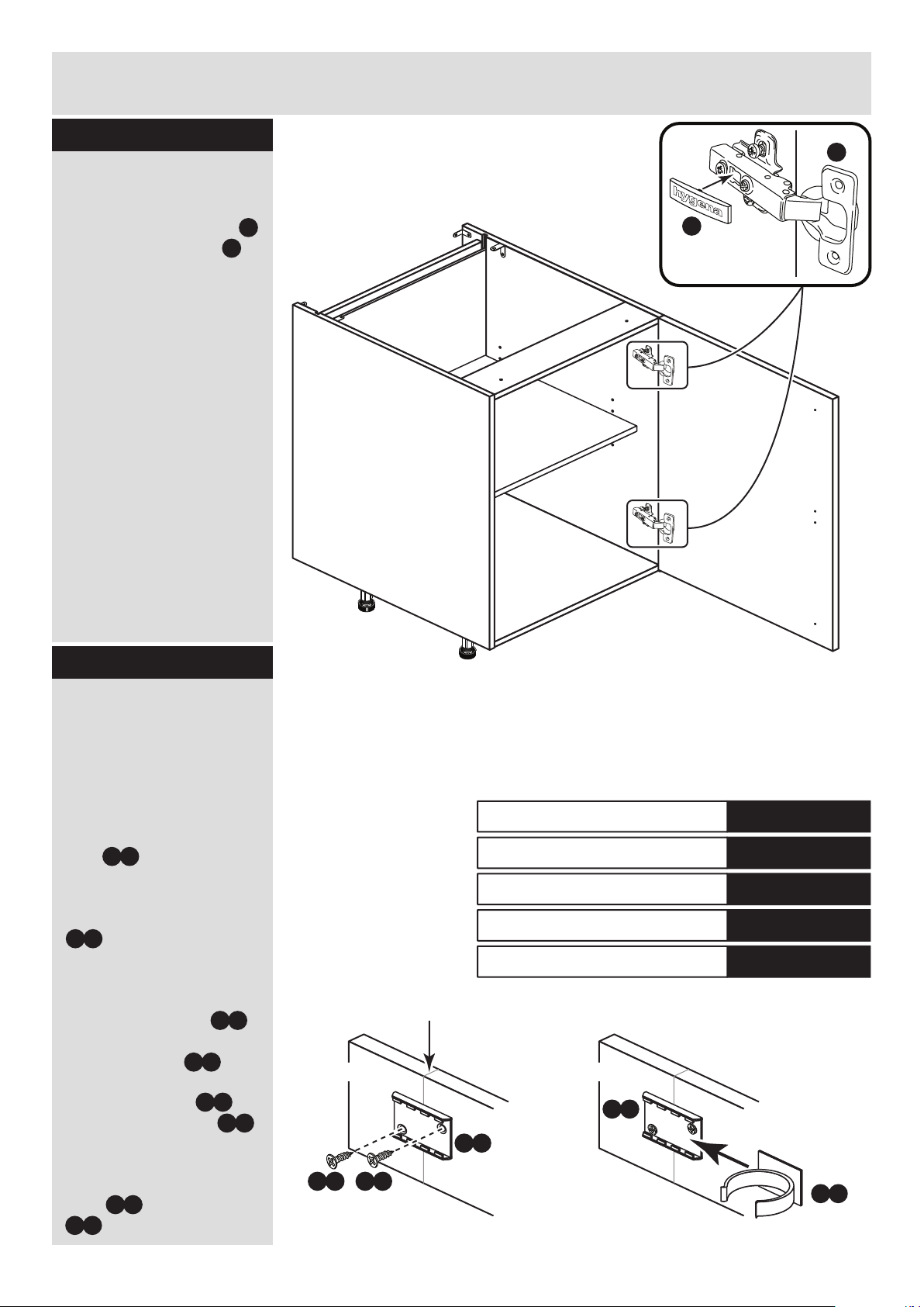
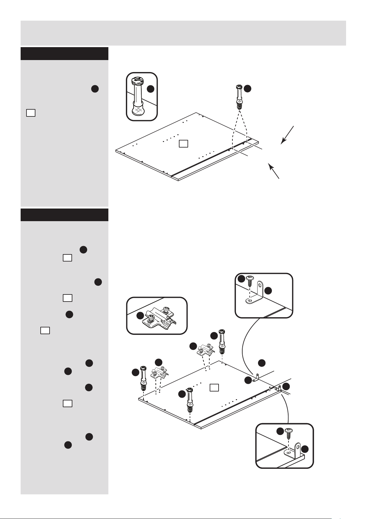
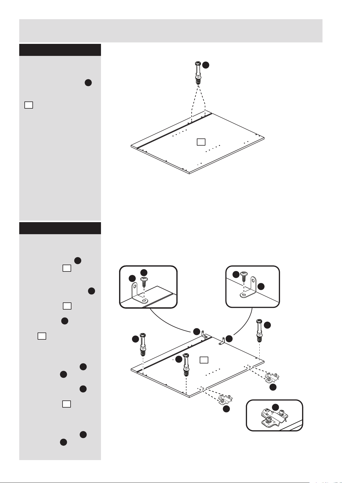
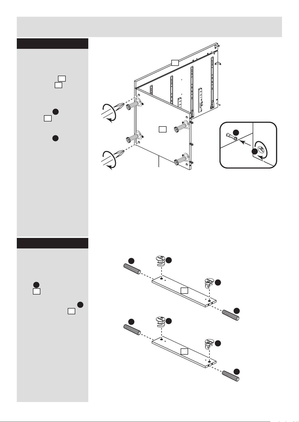
Step 2
L
Prepare the left side
Refer to step 1 and, if
required, fit 2 hinge
plates onto the left
side , making sure
that the slot is facing
towards the front edge.
Screw 4 metal dowels
into the holes shown on
the left side .
Note: Tighten metal
dowels up fully against
the panels.
Fit a bracket flush to
the top edge of the left
side , about 150mm
in from the groove, see
diagram.
Secure the bracket
using screw .
Fit another bracket
flush to the back edge of
the left side , about
5mm down from the top
edge, see diagram.
Secure the bracket
using screw .
Note: The brackets must
be flush with the
top/back edge of the
panel.
1
B
1
J
J
1
J
1
E
J
E
B
B
B
B
L
L
5mm
150mm
J
J
J
E
1
B
1
L
J
E
Page 6
5mm
150mm
5
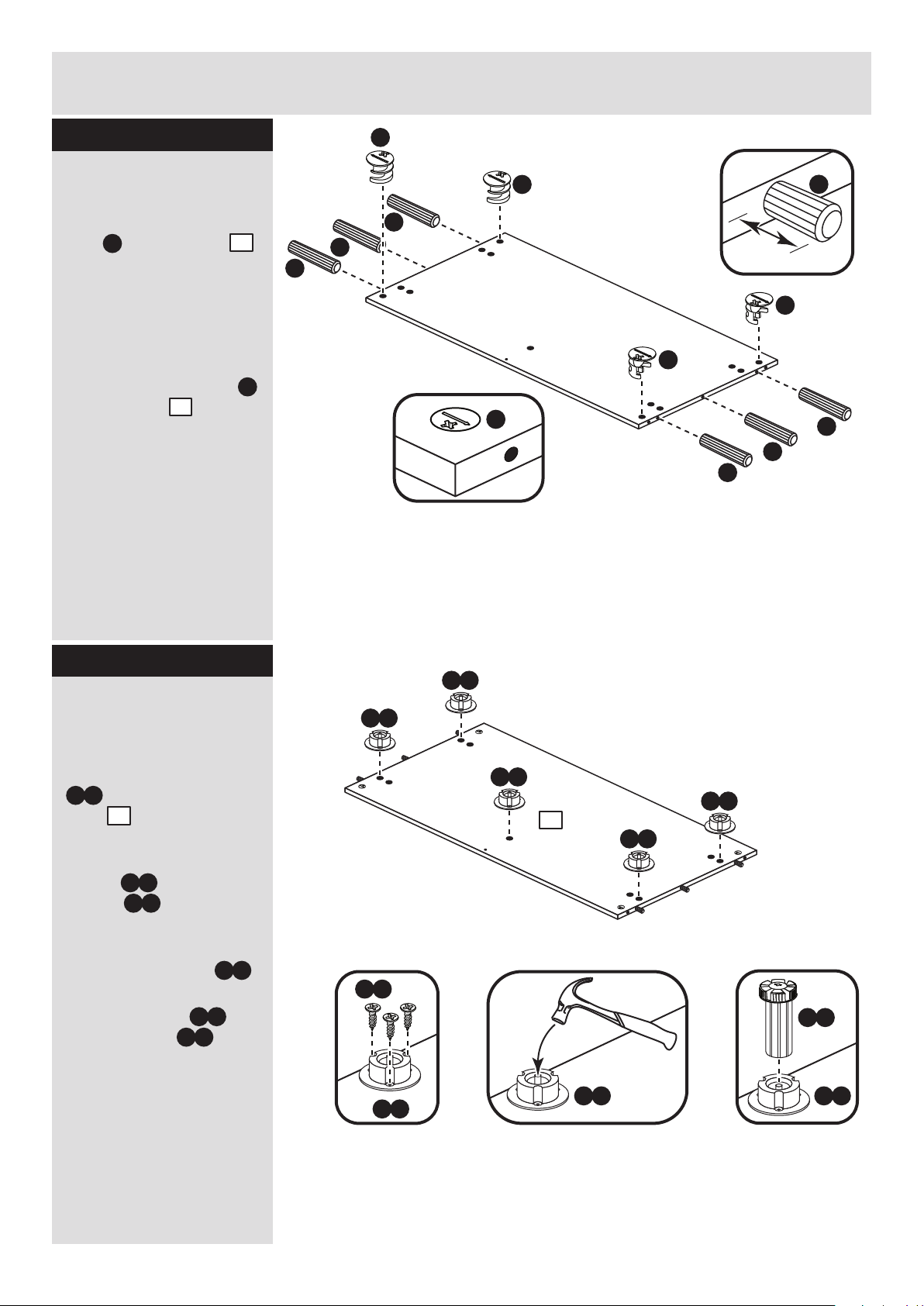
Step 3
A
A
A
Assembly Instructions
Step 4
L
Prepare the right side
Refer to step 1 and, if
required, fit 2 hinge
plates onto the right
side , making sure
that the slot is facing
towards the front edge.
Screw 4 metal dowels
into the holes shown on
the right side .
Fit a bracket flush to
the top edge of the right
side , about 150mm
in from the groove, see
diagram.
Secure the bracket
using screw .
Fit another bracket
flush to the back edge of
the right side , about
5mm down from the top
edge, see diagram.
Secure the bracket
using screw .
2
B
2
J
J
2
J
2
E
J
E
Prepare the base
Insert 4 large locking
nuts into the base
as shown.
Note: Arrow on locking
nut must point towards
hole in edge of panel.
Tap 6 wooden dowels
into the base as
shown.
Note: Wooden dowels
must not stick out from
the edge by more than
10mm or they may
damage other panels.
C
C
3
10mm
A
A
3
A
A
A
C
C
C
C
3
L
2
J
J
J
E
B
B
B
B
L
2
L
J
E
Page 7
Assembly Instructions
6
Step 5
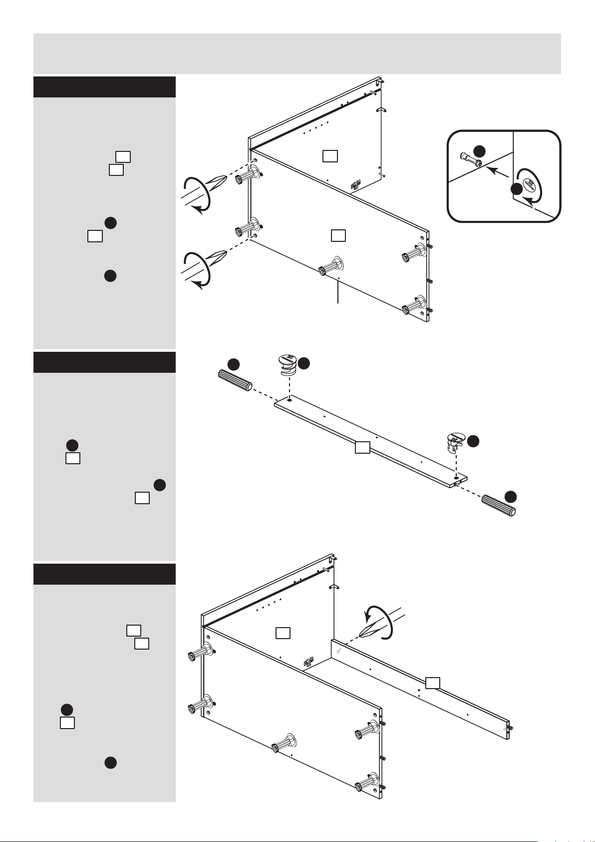
Step 6
Step 7
4
A
A
C
C
C
Prepare the 2 cross
rails
Insert 2 large locking
nuts into the cross
rails as shown.
Tap 2 wooden dowels
into the cross rails as
shown.
4
4
A
Finished
front edge
Join the right side and
base
Push the base onto
the right side .
Use a screwdriver to
tighten the 2 large
locking nuts fitted to
the base .
Note: Turn the large
locking nuts as far as
they will go - more than
1/2 a turn.
B
C
2
3
3
3
2
C
C
I aI a
I b
b: c: d:
I a
I a
I a
I a
3
Fit the legs to the
base
a: Push the leg sockets
. into the holes in the
base as shown.
b: Secure each leg
socket with 3
screws .
c: Tap in the centre plug
on each leg socket .
d: Push the leg into
the leg socket .
I a
I a
I a
I e
I e
3
x 3
I a
I a
I b
x 2
Page 8
Assembly Instructions
7
Step 8
Step 9
Fit the left side
Push the left side
onto the assembly.
Use a screwdriver to
tighten the large locking
nut fitted to the 2
cross rails and the 2
fitted to the base .
Note: Turn the large
locking nuts as far as
they will go - more than
1/2 a turn.
3
1
C
C
4
4
2
Fit the 2 cross rails
Push each cross rail
onto the right side .
Use a screwdriver to
tighten the large locking
nut fitted to each
cross rail .
Note: Turn the large
locking nuts as far as
they will go - more than
1/2 a turn.
4
4
2
C
C
4
Support this cross rail
until the left side has been
fitted in the next step.
2
4
4
1
4
3
Page 9
Assembly Instructions
8
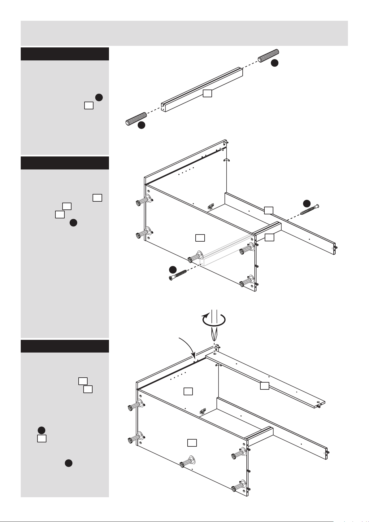
Step 10
Step 11
Secure the back
The bottom edge of the
back must be flush
with the bottom edge of
the base .
Secure the back to
the back edge of the
base using 3 screws
. .
Stand the unit up for
the next stage.
6
6
3
3
F
Fit the back
Slide the back along
the grooves in the side
panels and .
6
1 2
6
2
4
3
2
4
1
3
6
F
F
F
1
Page 10
Assembly Instructions
9
Step 12
Secure the unit to the
wall
Using the brackets
fitted to the back edge of
the sides and
screw the unit to the
wall.
Fixings are not supplied
as they will need to suit
the wall type, and the
length of screw will
depend on the distance
of the back of the unit to
the wall.
J
5mm
Warning: Take
care when
drilling the wall
that you do not
drill into any pipes, wires
etc. If in doubt, consult
an expert.
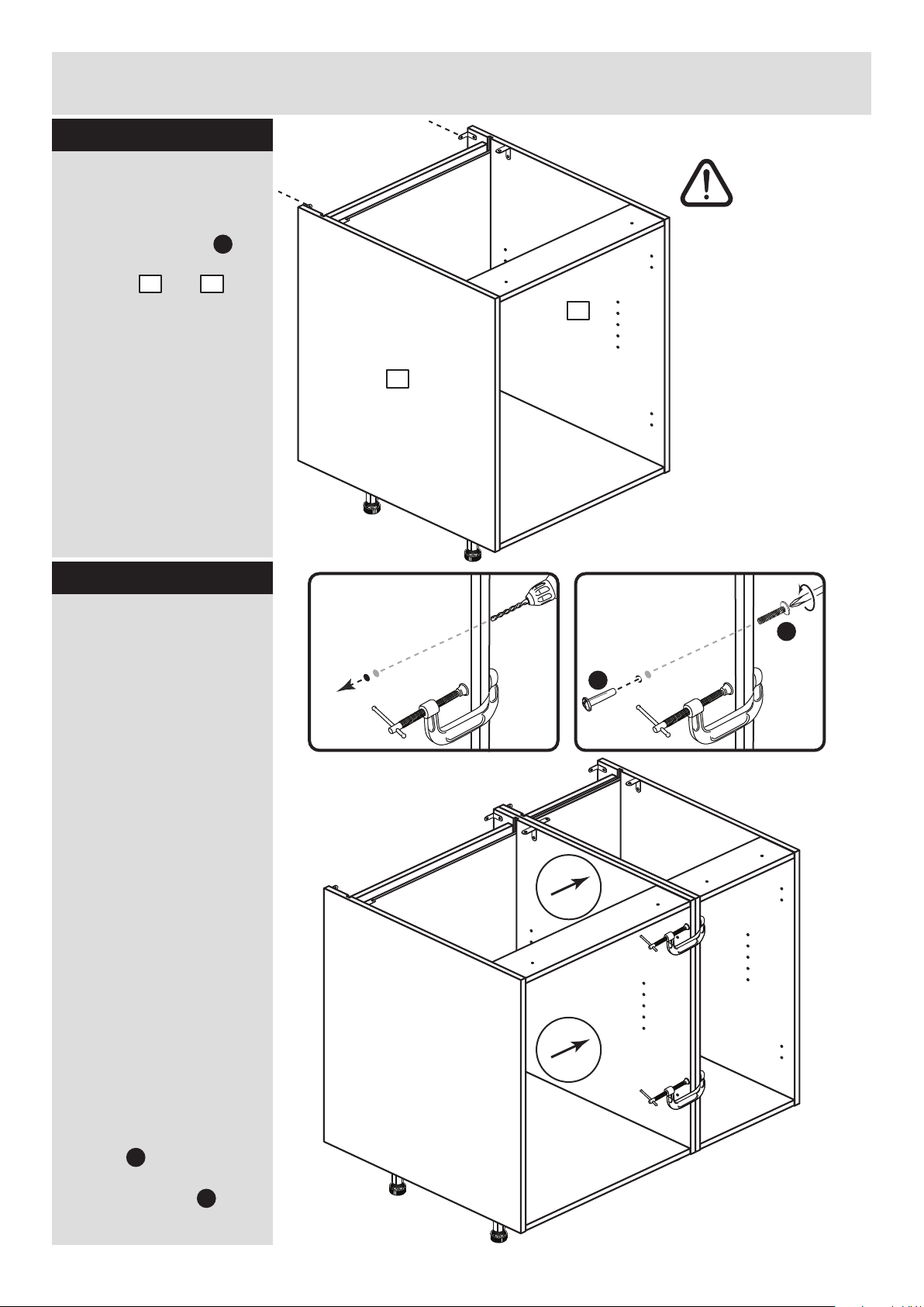
Step 13
Joining units together
Fittings have been
supplied so you are able
to join units together.
Make sure that your first
unit is level.
Push the other unit up
against first unit and
ensure both units are
level.
Check that the ends are
flush and in line, then
clamp them together.
Using a 5mm drill bit,
drill 2 holes (approximate
positions shown circled)
in the side panel into the
adjoining side panel of
the other unit.
Push the connecting
sleeves into the holes
and then screw the
connecting bolts in
from the other side.
G
H
G
H
1
2
1 2
Page 11
Assembly Instructions
10
Step 14
Fit the loose shelf
Insert 4 shelf studs at
the required height.
Lower the loose shelf
down onto the shelf
studs .
Step 16
K
K
5
Prepare the door
Push fit the 2 hinges
into the door .
Secure each hinge with
2 screws .
Note: Before securing
with the screws, make
sure that the hinges are
positioned at 90 degrees
with the front edge of the
door.
Step 15
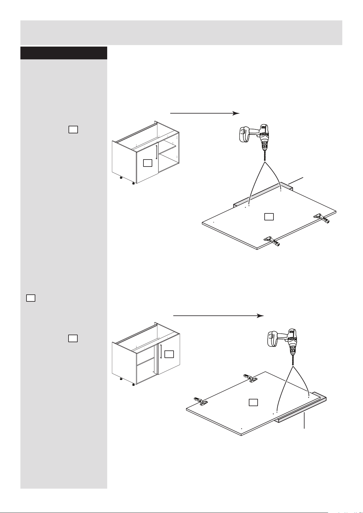
Fit the unit to worktop
To fit the unit to the
worktop use 2 screws
to screw up through the
holes in the cross rail
as shown.
Then use 2 screws to
screw up through the
brackets as shown.
D
M
7
F
E
J
4
7
M
M
90
M
D
D
D
D
1
2
K
x 4
5
F
F
E
E
4
Page 12
Assembly Instructions
11
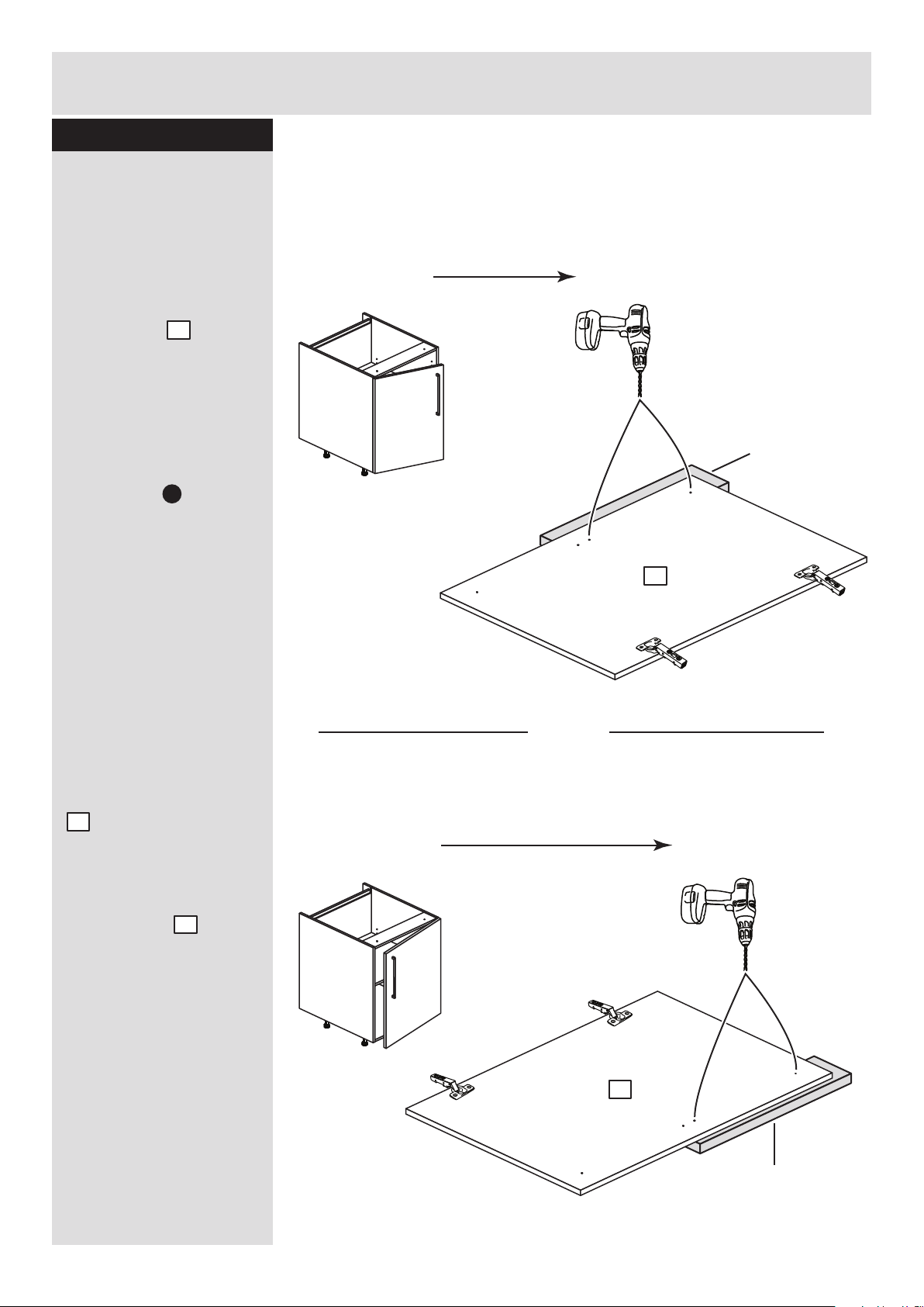
Step 17
Small piece of
waste wood
Drill these 2 holes if
you have fitted the
hinges to the left side.
Drill these 2 holes if you
have fitted the hinges
to the right side.
DO NOT drill
any other holes
DO NOT drill
any other holes
or
Drill the handle holes
in the door
Important: Please follow
these instructions
carefully.
Lay the door down
onto a smooth surface.
Important: Carefully
choose which holes you
need to drill.
This will depend on
which side you fitted the
hinge plates .
Check that the holes and
hinges are in the same
place as the diagrams.
Note: We recommend
the use of a small piece
of waste wood, placed
behind the hole while
drilling, to reduce the
possibility of any
breakout.
Using the pilot hole in
the rear face of the door,
. drill through the
holes indicated opposite,
using a 2.5mm diameter
drill.
Turn the door over
and open out the 2.5mm
holes that you have just
drilled by drilling back
through them with a
5mm drill.
Note: Drill bits are not
provided.
7
L
7
7
ONLY drill
these 2 holes
ONLY drill
these 2 holes
Small piece of
waste wood
7
7
PLEASE FOLLOW THESE INSTRUCTIONS CAREFULLY
TO CHOOSE WHICH 2 HOLES YOU WILL NEED TO DRILL
Page 13
O a
Assembly Instructions
12
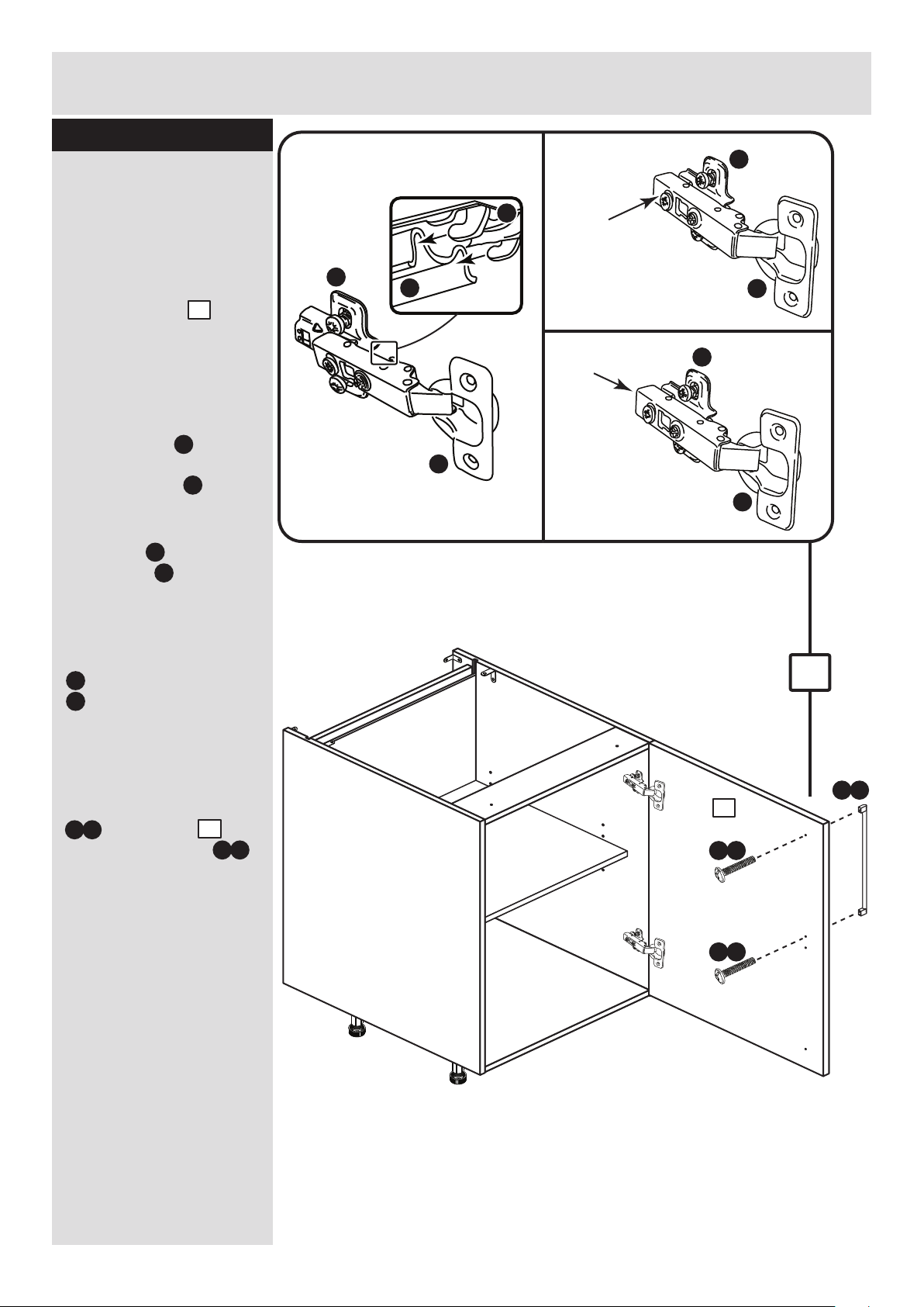
Step 18
a:
b:
c:
This shows the door being fitted to hinge
plates on the right side.
You may have fitted them to the left side.
Push and
click
Push
d:
Fit door and handle
2 people are needed
here
Note: The easiest way to
attach the door is to
fit the top hinge first,
then align and fit the
other hinge.
a: Push the hooks on
the hinge arm
underneath the front of
the hinge plate .
b: Press the front of the
hinge arm against the
hinge plate until it
clicks into place.
c: If you need to
seperate the hinge arm
. from the hinge plate,
. press the button at
the end of the hinge arm
and lift it off of the hinge
plate.
d: Attach the handle
. to the door
using the 2 screws
packed with it.
L
M
M
L
L
M
L
M
L
L
M
7
M
L
M
O a
O b
7
b
7
O b
O b
Page 14
Assembly Instructions
13
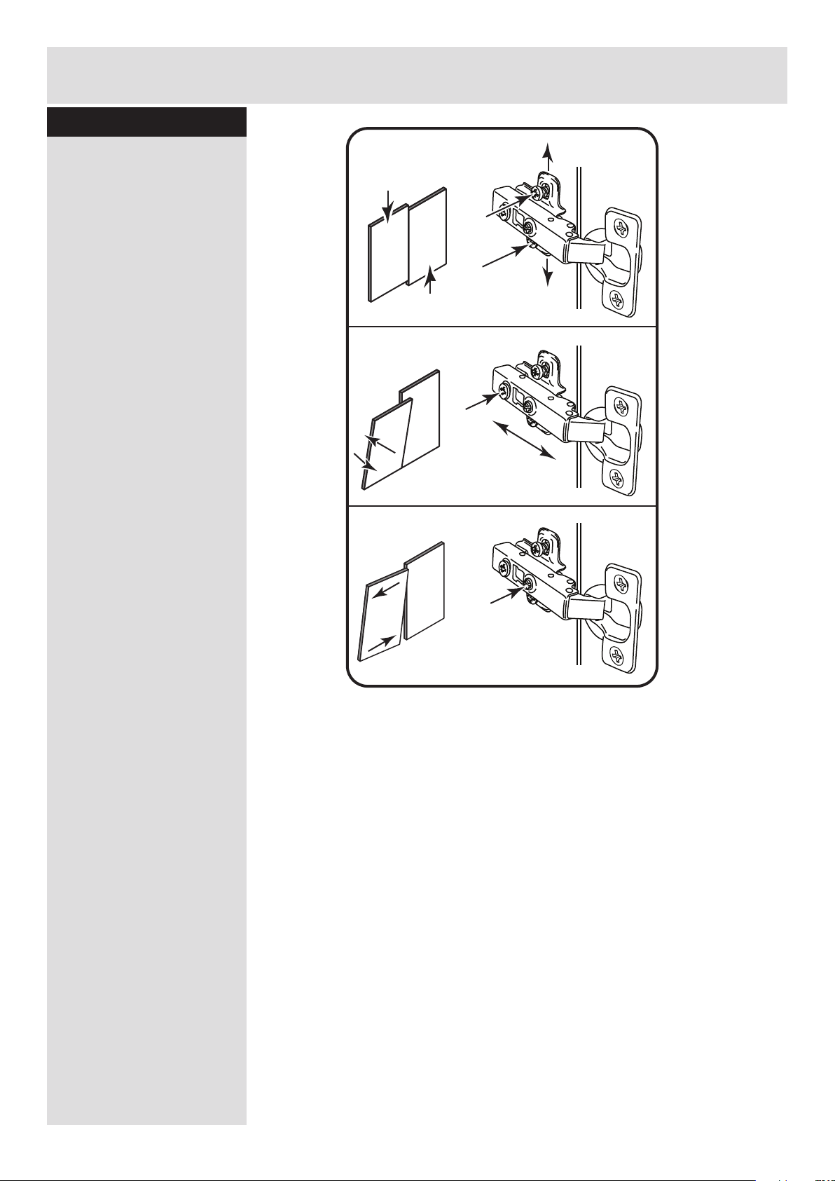
Step 19
Adjust the door if
needed
a: Height adjustment.
Loosen screws A on
hinge plates and move
door up or down as
required.
Retighten screw A.
b: Forward and Back
adjustment.
Loosen screw B on hinge
arm and move door in or
out as required.
Retighten screw B.
c: Sideways
adjustment.
To move door ‘out’
loosen screw C.
To move door ‘in’ tighten
screw C
a:
b:
c:
A
A
C
B
Page 15
Assembly Instructions
14
Step 20
Fit the hinge covers
Push the hinge covers
onto the hinge arms .
Step 21
N
M
h
ygen
a
N
M
Pencil mark
Plinth
I c
I c
I d
Plinth
I e I e
Fit the plinth
After cutting the plinth to
the required length, offer
the plinth up to the unit
and using a pencil, mark
the position of the unit’s
legs on the back of
the plinth.
Position the leg bracket
. so it is in the centre
of the pencil mark and
half way up the plinth.
Fix the leg bracket
to the back of the plinth
using 2 screws .
Slide the leg clip
into the leg bracket
Offer the plinth up to the
unit and push the leg
clips onto the legs
. .
I b
I b
I c
I c
I c
I d
I d
.
I e
608/2345
608/2369
205/5668
198/9917
608/2352
Black Plinth Pack
Cream Plinth Pack
Oak Plinth Pack
White HN Plinth Pack
White Gloss Plinth Pack
Page 16
Assembly Instructions
15
If you need help or have damaged or missing parts, call the Customer Helpline: 08456 400800
and quote the reference numbers on the component pages.
Argos Ltd, 489-499 Avebury Boulevard, Central Milton Keynes, MK9 2NW
Step 22
ALR2651
Fit other products to
the unit
To fit other products to
this unit e.g. worktops
etc., please follow the
instructions packed with
them.
We recommend that you
consult a qualified joiner
or kitchen fitter.
Assembly is complete
Warning: The
unit is heavy.
Lift with care.
Page 17
MADE IN
BRITAIN
Assembly Instructions - Please keep for future reference
Dimensions
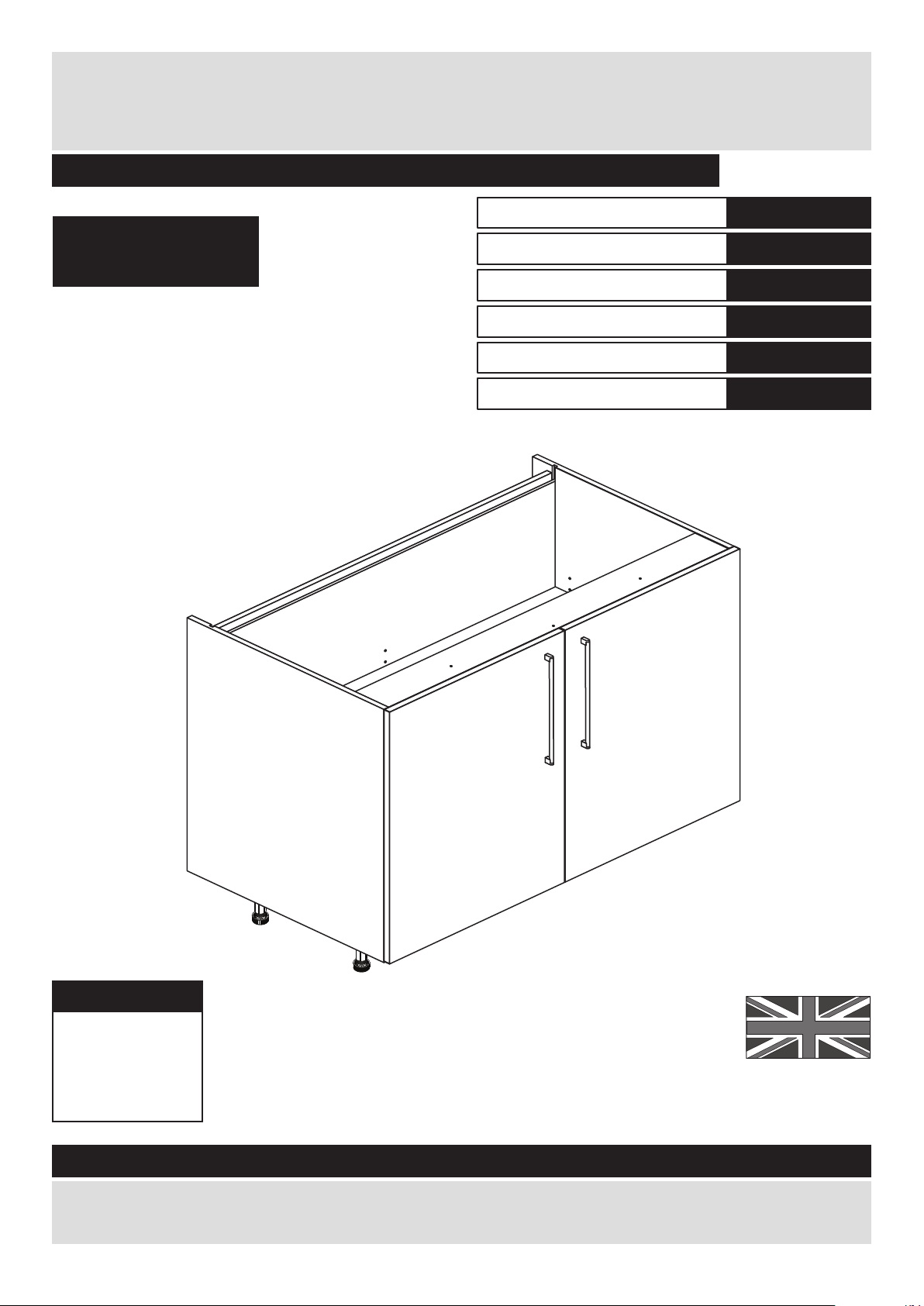
Width - 100cm
Depth - 59cm
Height - 87cm
Valencia - 1000mm Base Cabinet
If you need help or have damaged or missing parts, call the Customer Helpline: 08456 400800
Issue 1 - 16/08/11
Important - Please read these instructions fully before starting assembly
hygena
656/5790
633/2882
633/2710
656/5295
656/4540
633/2806
Cabinet
Black Door Pack
Cream Door Pack
Grey Door Pack
Plum Door Pack
White Door Pack
Page 18
Safety and Care Advice
Important - Please read these instructions fully before starting assembly
• Warning: This unit weighs
approximately 26kgs.
Please lift with care.
• Check you have all the
components and tools listed on
pages 2, 3 and 4.
• Remove all fittings from the
plastic bags and separate them
into their groups.
• Keep children and animals
away from the work area, small
parts could choke if swallowed.
• Parts of the assembly will be
easier with 2 people.
• Make sure you have enough
space to layout the parts before
starting.
• Do not stand or put weight on
the product, this could cause
damage.
• Assemble the item as close to
its final position (in the same
room) as possible.
• Assemble on a soft level
surface to avoid damaging the
unit or your floor (use opened
out unit carton).
• We do not
recommend the
use of power
drill/drivers for
inserting screws,
as this could damage the unit.
Only use hand screwdrivers.
• Safety note: If there is any
chance of this unit being pulled
over by children etc. it is
recommended that the unit is
secured to a wall using suitable
fixings (not supplied).
• Dispose of all packaging
carefully and responsibly.
1
Care and maintenance
• Only clean using a damp cloth
and mild detergent, do no use
bleach or abrasive cleaners.
• From time to time check that
there are no loose screws on
this unit.
• This product should not be
discarded with household
waste. Take to your local
authority waste disposal centre.
Note: If required the next page
can be cut out and used as
reference throughout the
assembly. Keep this page with
these instructions for future
reference.
Tools required
Rule Scissors Hammer
Eye protection
(when using a
hammer or drill)
Cross-head
screwdriver
Electric drill
Page 19
Components - Panels
Please check you have all the panels listed below
2
1
If you have damaged or missing components, call the
Customer Helpline: 08456 400800 quoting the reference
numbers below
5
2
6
4
3
Left Side (DPF068A)
(720 x 560mm)
Right Side (DPF069A)
(720 x 560mm)
Loose Shelf (DPF083A)
(968 x 431mm)
Base (DPF082A)
(969 x 494mm)
Back (DPF085A)
(979 x 680mm)
8
Cross Rail (DPF084A)
(969 x 96mm) x 2
Muntin Rail (DPF086A)
(36 x 688mm)
7
Valencia Door (DPF147B)
(497 x 716mm) x 2
The front surface
of this door is
protected with a
peel-off film
Page 20
Please check you have all the fittings listed below
3
Components - Fittings
If you have damaged or missing components, call the
Customer Helpline: 08456 400800 quoting the reference
numbers below
Note: The quantities below are the correct amount to complete the assembly. In some cases
more fittings may be supplied than are required.
A
Wooden dowel (F22) x 12
B
Metal dowel (F901) x 8
C
D
Large locking
nut (F900) x 8
F
G H I a
I c
I d
I e
I b
Ruler - Use this ruler to help correctly identify the screws
mm 10 20 30 40 50 60 70 80 90 100 110 120 130 140 150 160 170
J K
13mm Screw (F63) x 8
E
13mm Screw (F79) x 6
Connecting Sleeve (F432) x 2 19mm Connecting bolt (F461) x 2
L M
25mm Screw (F50) x 6
N
Hinge Cover (F119) x 4
Bracket (F945) x 4
Shelf support (F110) x 6
Hinge Plate
(F117) x 4
Hinge Arm (F118) x 4
Leg Bracket
(F127) x 3
Leg Socket
(F120) x 5
Leg Clip
(F128) x 3
16mm Screw
(F129) x 21
Leg (F122) x 5
h
ygen
a
O
40mm Screw (F910) x 2
PPa
b
25mm Screw (F132) x 4
Handle (F214) x 2
Page 21
Assembly Instructions
If you have damaged or missing components, call the
Customer Helpline: 08456 400800 quoting the reference
numbers below
Step 1
B
B
B
L
L
J
J
J
E
1
L
J
E
5mm
150mm
Only screw ONE metal dowel into
one of these holes.
1st 5mm hole
2nd 5mm hole
B
B
1
Prepare the left side
Fit 2 hinge plates onto
the left side ,
orientated as shown.
Screw 3 metal dowels
into the holes shown on
the left side .
Fit a bracket flush to
the top edge of the left
side , about 150mm
in from the groove, see
diagram.
Secure the bracket
using screw .
Fit another bracket
flush to the back edge of
the left side , about
5mm down from the top
edge, see diagram.
Secure the bracket
using screw .
Note: The brackets must
be flush with the
top/back edge of the
panel.
B
1
J
J
1
J
1
E
J
E
Step 2
Prepare the left side
Screw a metal dowel
into one of the holes
shown on the left side
. .
Note: Tighten metal
dowels up fully against
the panels.
B
1
B
4
L
1
If you ARE fitting a sink unit
we recommend that you
use the 2nd 5mm hole.
If you ARE NOT fitting a sink
unit we recommend that
you use the 1st 5mm hole.
Page 22
Assembly Instructions
5
Step 3
Prepare the right side
Screw a metal dowel
into one of the holes
shown on the right side
. .
Use the same hole that
you used for the left side
in step 1.
L
Prepare the right side
Fit 2 hinge plates onto
the right side ,
orientated as shown.
Screw 3 metal dowels
into the holes shown on
the right side .
Fit a bracket flush to
the top edge of the right
side , about 150mm
in from the groove, see
diagram.
Secure the bracket
using screw .
Fit another bracket
flush to the back edge of
the right side , about
5mm down from the top
edge, see diagram.
Secure the bracket
using screw .
2
B
2
J
J
2
J
2
E
J
E
Step 4
J
E
J
E
L
L
L
B
B
B
J
J
2
Only screw ONE metal dowel
into one of these holes (use
the same hole that you used
for the left side in step 1).
B
B
2
2
Page 23
Assembly Instructions
6
Step 5
Step 6
I a I a
I b
b:
a:
c: d:
Fit the legs to the
base
a: Push the leg sockets
. into the holes in the
base as shown.
b: Secure each leg
socket with 3
screws .
c: Tap in the centre plug
on each leg socket .
d: Push the leg into
the leg socket .
I a
I a
I a
I e
I e
3
x 3
I a
I a
I b
I a
I a
I a
I a
3
Prepare the base
Insert 4 large locking
nuts into the base
as shown.
Note: Arrow on locking
nut must point towards
hole in edge of panel.
Tap 6 wooden dowels
into the base as
shown.
Note: Wooden dowels
must not stick out from
the edge by more than
10mm or they may
damage other panels.
C
C
3
10mm
A
A
3
A
A
A
A
A
C
C
A
C
C
I a
Page 24
A
Assembly Instructions
7
Step 7
Step 8
Finished
front edge
C
Prepare the 2 cross
rails
Insert 2 large locking
nuts into the cross
rails as shown.
Tap 2 wooden dowels
into the cross rails as
shown.
Step 9
4
4
A
Join the right side and
base
Push the base onto
the right side .
Use a screwdriver to
tighten the 2 large
locking nuts fitted to
the base .
Note: Turn the large
locking nuts as far as
they will go - more than
1/2 a turn.
B
F
3
3
2
C
C
2
3
2
A
4
Fit a cross rail
Push a cross rail
onto the right side as
shown.
Use a screwdriver to
tighten the large locking
nut fitted to the cross
rail .
Note: Turn the large
locking nuts as far as
they will go - more than
1/2 a turn.
2
C
C
4
C
C
4
4
Page 25
O
Assembly Instructions
8
Step 10
Step 11
Prepare the muntin
rail
Tap 2 wooden dowels
into the muntin rail as
shown.
3
4
A
A
A
8
8
Fit the muntin rail
Attach the muntin rail
to the base and
cross rail and secure
with 2 screws .
O
8
8
3
4
O
Step 12
3
4
Support this cross rail
until the left side has been
fitted in the next step.
4
Fit a cross rail
Push a cross rail
onto the right side as
shown.
Use a screwdriver to
tighten the large locking
nut fitted to the cross
rail .
Note: Turn the large
locking nuts as far as
they will go - more than
1/2 a turn.
2
C
C
4
2
If you are fitting a sink
unit you will need to fit
this support rail here
(refer back to step 3).
Page 26
Assembly Instructions
9
Step 13
Step 14
2
3
Fit the left side
Push the left side
onto the assembly.
Use a screwdriver to
tighten the large locking
nut fitted to the 2
cross rails and the 2
fitted to the base .
Note: Turn the large
locking nuts as far as
they will go - more than
1/2 a turn.
3
1
C
C
4
4
4
1
2
1
Fit the back
Slide the back along
the grooves in the side
panels and .
6
6
1 2
Page 27
Assembly Instructions
10
Step 15
Step 16
Secure the back
The bottom edge of the
back must be flush
with the bottom edge of
the base .
Secure the back to
the back edge of the
base using 4 screws
. .
Stand the unit up for
the next stage.
6
6
3
3
F
F
F
F
F
6
3
Secure the unit to the
wall
Using the brackets
fitted to the back edge of
the sides and
screw the unit to the
wall.
Fixings are not supplied
as they will need to suit
the wall type, and the
length of screw will
depend on the distance
of the back of the Unit to
the wall.
F
Warning: Take care when
drilling the wall that you do not
drill into any pipes, wires etc. If
in doubt, consult an expert.
1 2
1
2
Page 28
Assembly Instructions
11
Step 17
Joining units together
Fittings have been
supplied so you are able
to join units together.
Make sure that your first
unit is level.
Push the other unit up
against first unit and
ensure both units are
level.
Check that the ends are
flush and in line, then
clamp them together.
Using a 5mm drill bit,
drill 2 holes (approximate
positions shown circled)
in the side panel into the
adjoining side panel of
the other unit.
Push the connecting
sleeves into the holes
and then screw the
connecting bolts in
from the other side.
G
H
5mm
G
H
Fit the loose shelf
Insert 6 shelf studs at
the required height. 2 in
each side and ,
1 in the back and 1 in
the munting .
Lower the loose shelf
down onto the shelf
studs .
K
K
5
K
x 2
K
x 2
K
x 2
Step 18
5
1
6
8
2
1
2
6
8
Page 29
Assembly Instructions
12
Step 19
Fit the unit to worktop
To fit the unit to the
worktop use 2 screws
to screw up through the
holes in the cross rail
as shown.
Then use 2 screws to
screw up through the
brackets as shown.
F
E
J
4
F
F
E
E
Step 20
Prepare the doors
Push fit 2 hinges into
each door .
Secure each hinge with
2 screws .
Note: Before securing
with the screws, make
sure that the hinges are
positioned at 90 degrees
with the front edge of the
door.
D
M
7
7
M
M
90
M
D
D
D
D
4
Page 30
Assembly Instructions
13
Step 21
Small piece of
waste wood
DO NOT drill
any other holes
DO NOT drill
any other holes
ONLY drill
these 2 holes
ONLY drill
these 2 holes
Small piece of
waste wood
7
7
This will be
the left door
This will be
the right door
Drill the handle holes
in the doors
Important: Please follow
these instructions
carefully.
Lay the doors down
onto a smooth surface.
Important: Carefully
choose which holes you
need to drill.
Check that the holes and
hinges are in the same
place as the diagrams.
Note: We recommend
the use of a small piece
of waste wood, placed
behind the hole while
drilling, to reduce the
possibility of any
breakout.
Using the pilot hole in
the rear face of the door
. , drill through the
holes indicated opposite,
using a 2.5mm diameter
drill.
Turn the door over
and open out the 2.5mm
holes that you have just
drilled by drilling back
through them with a
5mm drill.
Note: Drill bits are not
provided.
7
7
7
7
7
PLEASE FOLLOW THESE INSTRUCTIONS CAREFULLY
TO CHOOSE WHICH 2 HOLES YOU WILL NEED TO DRILL
Page 31

Assembly Instructions
14
Step 22
a:
b:
c:
Push and
click
Push
d:
Fit doors and handles
2 people are needed
here
Note: The easiest way to
attach the door is to
fit the top hinge first,
then align and fit the
other hinge.
a: Push the hooks on
the hinge arm
underneath the front of
the hinge plate .
b: Press the front of the
hinge arm against the
hinge plate until it
clicks into place.
c: If you need to
seperate the hinge arm
. from the hinge plate,
. press the button at
the end of the hinge arm
and lift it off of the hinge
plate.
d: Attach a handle
to each door using
the screws packed
with them.
L
M
M
L
L
M
L
M
L
L
M
7
M
L
M
P a
7
P a
7
7
P a
P b
P b
P b
Page 32

Assembly Instructions
15
Step 23
Adjust the door if
needed
a: Height adjustment.
Loosen screws A on
hinge plates and move
door up or down as
required.
Retighten screw A.
b: Forward and Back
adjustment.
Loosen screw B on hinge
arm and move door in or
out as required.
Retighten screw B.
c: Sideways
adjustment.
To move door ‘out’
loosen screw C.
To move door ‘in’ tighten
screw C
a:
b:
c:
A
A
C
B
Page 33

Assembly Instructions
16
Step 24
Fit the hinge covers
Push the hinge covers
onto the hinge arms .
Step 25
N
M
h
ygen
a
N
M
Pencil mark
Plinth
I c
I c
I d
Plinth
I e I e
608/2345
608/2369
608/3784
608/3791
608/2352
Black Plinth Pack
Cream Plinth Pack
Grey Plinth Pack
Plum Plinth Pack
White Plinth Pack
Fit the plinth
After cutting the plinth to
the required length, offer
the plinth up to the unit
and using a pencil, mark
the position of the unit’s
legs on the back of
the plinth.
Position the leg bracket
. so it is in the centre
of the pencil mark and
half way up the plinth.
Fix the leg bracket
to the back of the plinth
using 2 screws .
Slide the leg clip
into the leg bracket
Offer the plinth up to the
unit and push the leg
clips onto the legs
. .
I b
I b
I c
I c
I c
I d
I d
.
I e
Page 34

Assembly Instructions
17
If you need help or have damaged or missing parts, call the Customer Helpline: 08456 400800
and quote the reference numbers on the component pages.
Argos Ltd, 489-499 Avebury Boulevard, Central Milton Keynes, MK9 2NW
Step 26
Fit other products to
the unit
To fit other products to
this unit e.g. worktops
etc., please follow the
instructions packed with
them.
We recommend that you
consult a qualified joiner
or kitchen fitter.
Assembly is complete
Warning: The
unit is heavy.
Lift with care.
Page 35

Page 36

ALR2653
Page 37

MADE IN
BRITAIN
Dimensions
Width - 50cm
Depth - 59cm
Height - 87cm
Valencia - 4 Drawer Cabinet
Assembly Instructions - Please keep for future reference
If you need help or have damaged or missing parts, call the Customer Helpline: 08456 400800
Issue 2 - 31/07/14
Important - Please read these instructions fully before starting assembly
hygena
656/5848
633/2909
633/2734
205/4528
633/2820
204/6718
R
Cabinet
Black Drawer Pack
Cream Drawer Pack
Oak Drawer Pack
White Gloss Drawer Pack
White HN Drawer Pack
Page 38
Safety and Care Advice
Important - Please read these instructions fully before starting assembly
• Warning: This unit weighs
approximately 16.5kgs.
Please lift with care.
• Check you have all the
components and tools listed on
pages 2, 3 and 4.
• Remove all fittings from the
plastic bags and separate them
into their groups.
• Keep children and animals
away from the work area, small
parts could choke if swallowed.
• Parts of the assembly will be
easier with 2 people.
• Make sure you have enough
space to layout the parts before
starting.
• Do not stand or put weight on
the product, this could cause
damage.
• Assemble the item as close to
its final position (in the same
room) as possible.
• Assemble on a soft level
surface to avoid damaging the
unit or your floor (use opened
out unit carton).
• We do not
recommend the
use of power
drill/drivers for
inserting screws,
as this could damage the unit.
Only use hand screwdrivers.
• Safety note: If there is any
chance of this unit being pulled
over by children etc. it is
recommended that the unit is
secured to a wall using suitable
fixings (not supplied).
• Dispose of all packaging
carefully and responsibly.
1
Care and maintenance
• Only clean using a damp cloth
and mild detergent, do no use
bleach or abrasive cleaners.
• From time to time check that
there are no loose screws on
this unit.
• This product should not be
discarded with household
waste. Take to your local
authority waste disposal centre.
Note: If required the next page
can be cut out and used as
reference throughout the
assembly. Keep this page with
these instructions for future
reference.
Page 39
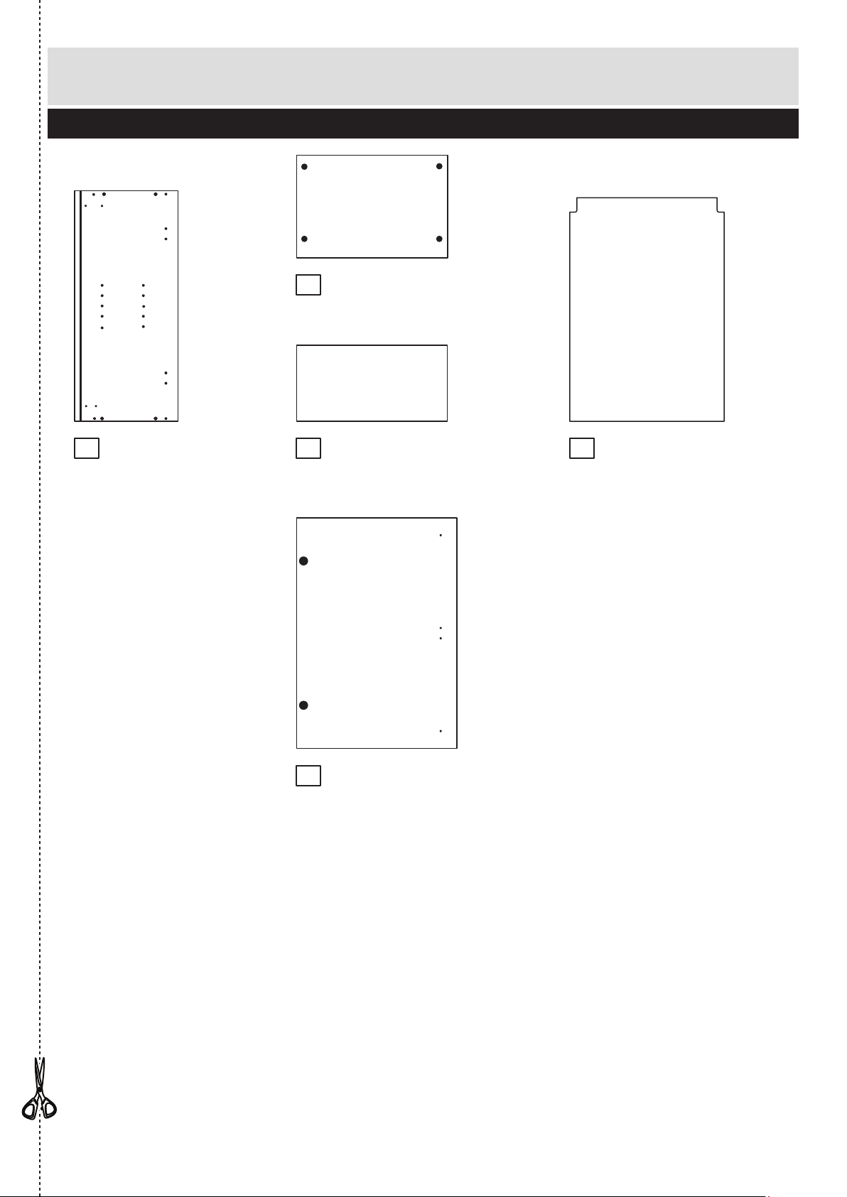
Components - Panels
Please check you have all the panels listed below
2
1
If you have damaged or missing components, call the
Customer Helpline: 08456 400800 quoting the reference
numbers below
2
7
4
3
Back (DPF077A)
(479 x 680mm)
6
Base (DPF074A)
(469 x 494mm)
Cross Rail (DPF076A)
(469 x 96mm) x 2
5
Drawer Back (DPF130A)
(439 x 98mm) x 4
Left Side (DPF087A)
(720 x 560mm)
Right Side (DPF088A)
(720 x 560mm)
Drawer Base (DPF129A)
(439 x 448mm) x 4
8
Drawer Front (DPF151B)
(497 x 176mm) x 4
Page 40

Please check you have all the fittings listed below
3
Components - Fittings
If you have damaged or missing components, call the
Customer Helpline: 08456 400800 quoting the reference
numbers below
Note: The quantities below are the correct amount to complete the assembly. In some cases
more fittings may be supplied than are required.
A
Wooden dowel (F22) x 10
B
Metal dowel (F901) x 8
C
D
Large locking
nut (F900) x 8
F
G H I a
I c
I d
I e
I b
J K
13mm Screw (F63) x 72
E
13mm Screw (F79) x 6
Connecting Sleeve (F432) x 2 19mm Connecting bolt (F461) x 2
L M
N O
S
P
Q
R
25mm Screw (F50) x 5
Bracket (F945) x 4
Leg Bracket
(F127) x 2
Leg Socket
(F120) x 4
Leg Clip
(F128) x 2
16mm Screw
(F129) x 16
Leg (F122) x 4
13mm Screw (F52) x 48
Left Runner (F139) x 4
L
R
Left Soft Close Unit (F141) x 4
Right Soft Close Unit (F142) x 4
Left Soft Close
Catch (F143) x 4
Right Soft Close
Catch (F144) x 4
Left Drawer
Side (F145) x 4
Right Drawer
Side (F146) x 4
L
R
Right Runner (F140) x 4
Door Handle
(F214) x 4
T a
T b
25mm Screw (F132) x 8
Page 41

Assembly Instructions
4
If you have damaged or missing components, call the
Customer Helpline: 08456 400800 quoting the reference
numbers below
Step 1
L
L
L
L
L
L
L
L
L
L
L
L
L
K
K
L
Fit the left runners to
the left side
Fit the 4 left runners
marked ‘L’ to the left
side .
The 1st screw uses
the 2nd hole in from the
front of the runner.
The 2nd screw uses
the 4th hole in from the
back of the runner.
The 3rd screw uses
the 8th hole in from the
back of the runner.
Fit left soft close units
to the left side
Fit the 4 left soft close
units . marked ‘L’ to
the left side using 3
screws .
1
1
1
1
Step 2
L
K
K
K
L
K
K
K
L
K
K
K
L
K
K
K
K
K
P
L
L
P
P
P
P
P
K
K
K
K
K
K
K
K
K
K
K
K
K
K
L
L
L
L
L
L
K
Page 42

Assembly Instructions
5
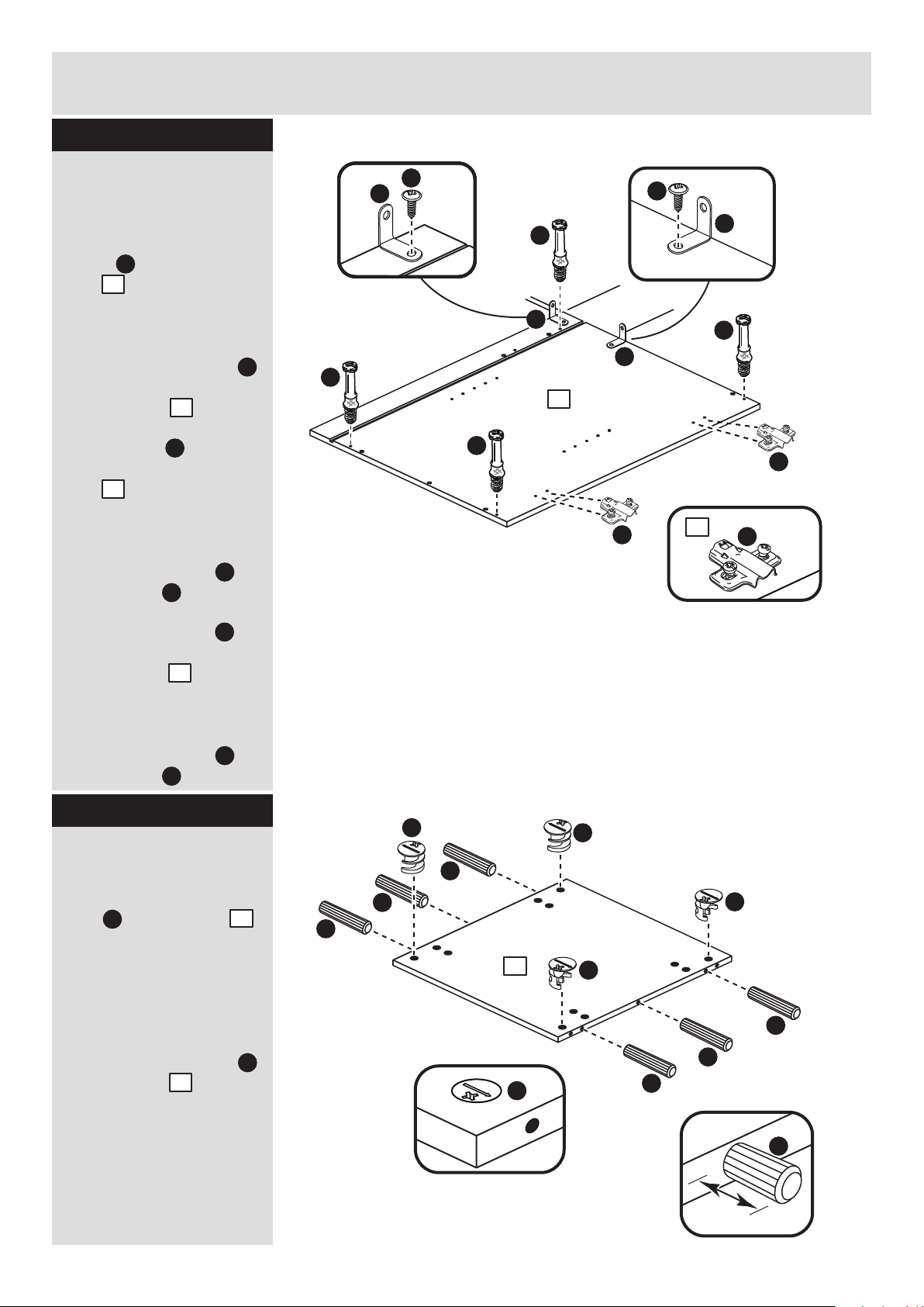
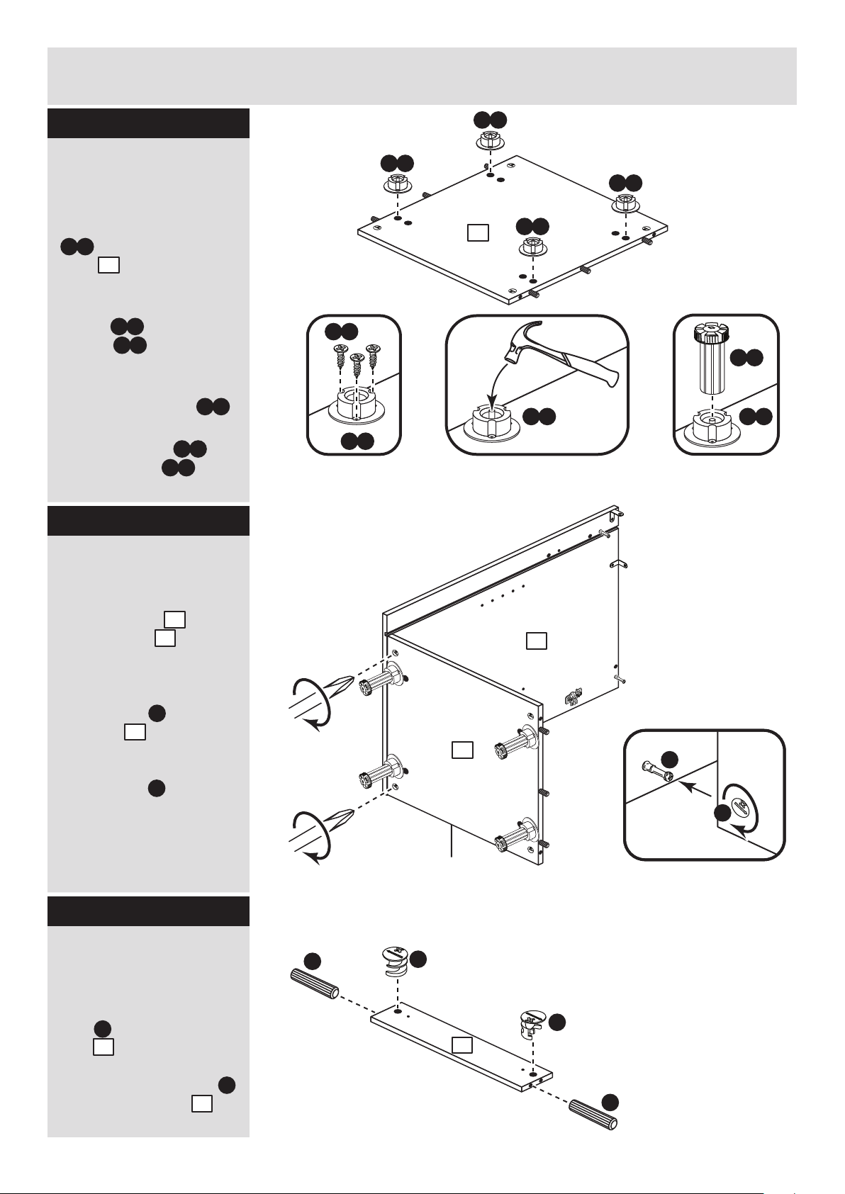
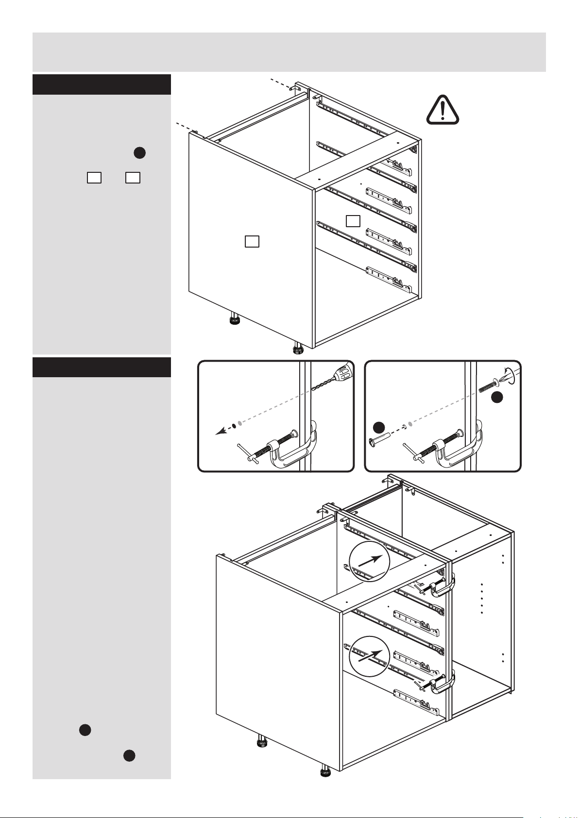
Step 3
Prepare the left side
Screw 4 metal dowels
into the holes shown on
the left side .
Note: Tighten metal
dowels up fully against
the panels.
Fit a bracket flush to
the top edge of the left
side , about 150mm
in from the groove, see
diagram.
Secure the bracket
using screw .
Fit another bracket
flush to the back edge of
the left side , about
5mm down from the top
edge, see diagram.
Secure the bracket
using screw .
B
1
J
J
1
J
1
E
J
E
J
E
B
J
E
L
L
L
L
L
L
L
L
L
L
L
L
B
B
B
B
5mm
150mm
J
J
R
R
R
R
R
R
Fit the right runners
to the right side
Fit the 4 right runners
marked ‘R’ to the right
side .
The 1st screw uses
the 2nd hole in from the
front of the runner.
The 2nd screw uses
the 4th hole in from the
back of the runner.
The 3rd screw uses
the 8th hole in from the
back of the runner.
2
2
K
K
K
Q
Step 4
Note: The brackets must
be flush with the top/back
edge of the panel.
Q
Q
Q
Q
Q
K
K
K
K
K
K
K
K
K
K
K
K
K
K
Page 43

Assembly Instructions
6
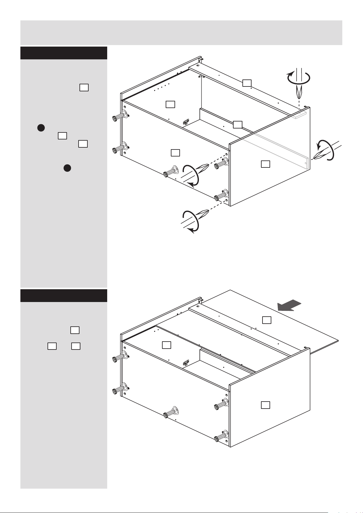
Step 5
Step 6
R
R
Fit soft close units to
the right side
Fit the 4 right soft close
units marked ‘R’ to
the right side using 3
screws .
2
K
N
R
R
R
R
R
R
R
R
2
R
R
R
R
2
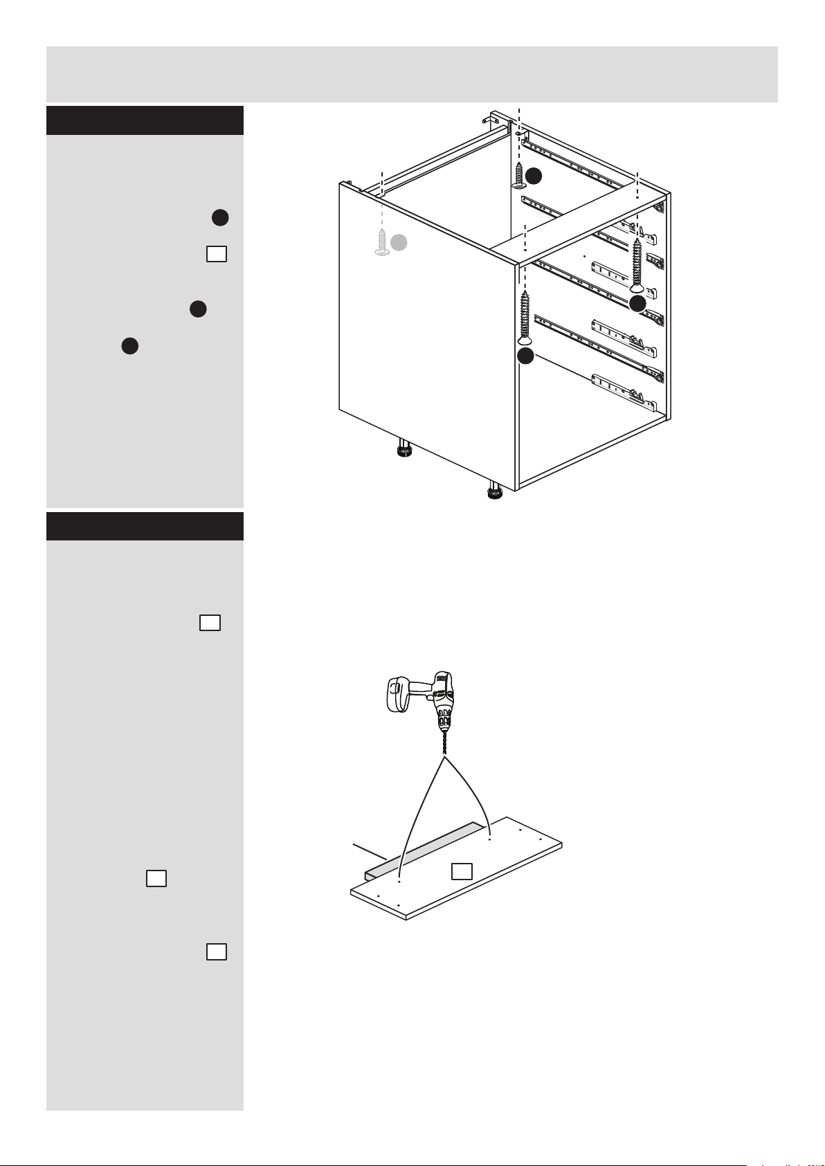
Prepare the right side
Screw 4 metal dowels
into the holes shown on
the right side .
Fit a bracket flush to
the top edge of the right
side , about 150mm
in from the groove, see
diagram.
Secure the bracket
using screw .
Fit another bracket
flush to the back edge of
the right side , about
5mm down from the top
edge, see diagram.
Secure the bracket
using screw .
B
2
J
J
2
J
2
E
J
E
J
J
J
E
B
B
B
B
J
E
R
R
R
R
N
N
N
N
N
K
K
K
K
K
K
K
K
K
K
K
K
K
Page 44

Assembly Instructions
7
Step 7
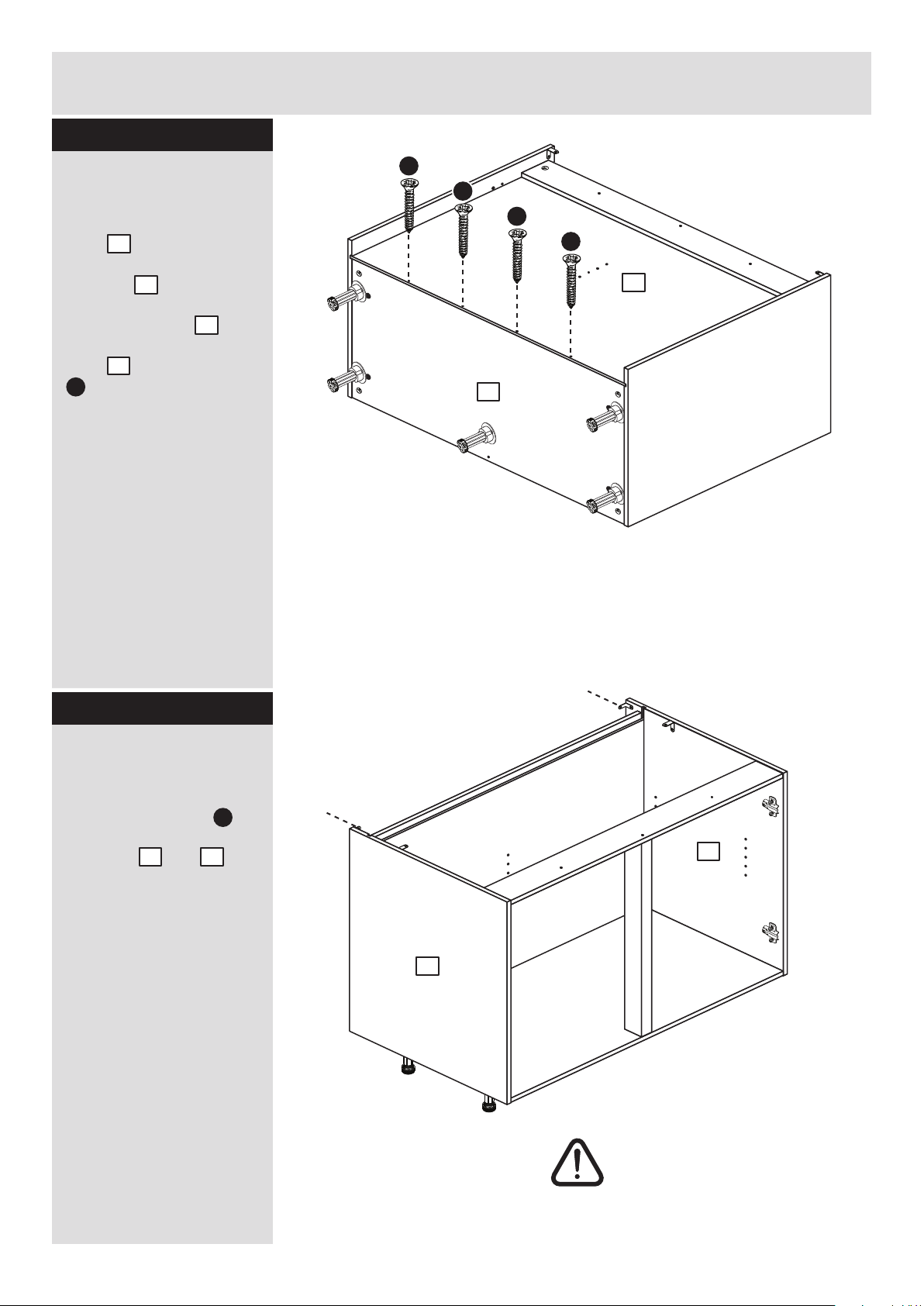
Step 8
A
A
A
Prepare the base
Insert 4 large locking
nuts into the base
as shown.
Note: Arrow on locking
nut must point towards
hole in edge of panel.
Tap 6 wooden dowels
into the base as
shown.
Note: Wooden dowels
must not stick out from
the edge by more than
10mm or they may
damage other panels.
C
C
3
10mm
A
A
3
A
A
A
C
C
C
C
3
I a I a
I b
b:
a:
c: d:
I a
I a
I a
I a
3
Fit the legs to the
base
a: Push the leg sockets
. into the holes in the
base as shown.
b: Secure each leg
socket with 3
screws .
c: Tap in the centre plug
on each leg socket .
d: Push the leg into
the leg socket .
I a
I a
I a
I e
I e
3
x 3
I a
I a
I b
Page 45
R
R
R
R
R
R
R
R
Assembly Instructions
8
Step 9
Step 10
4
A
A
C
C
4
A
A
C
C
C
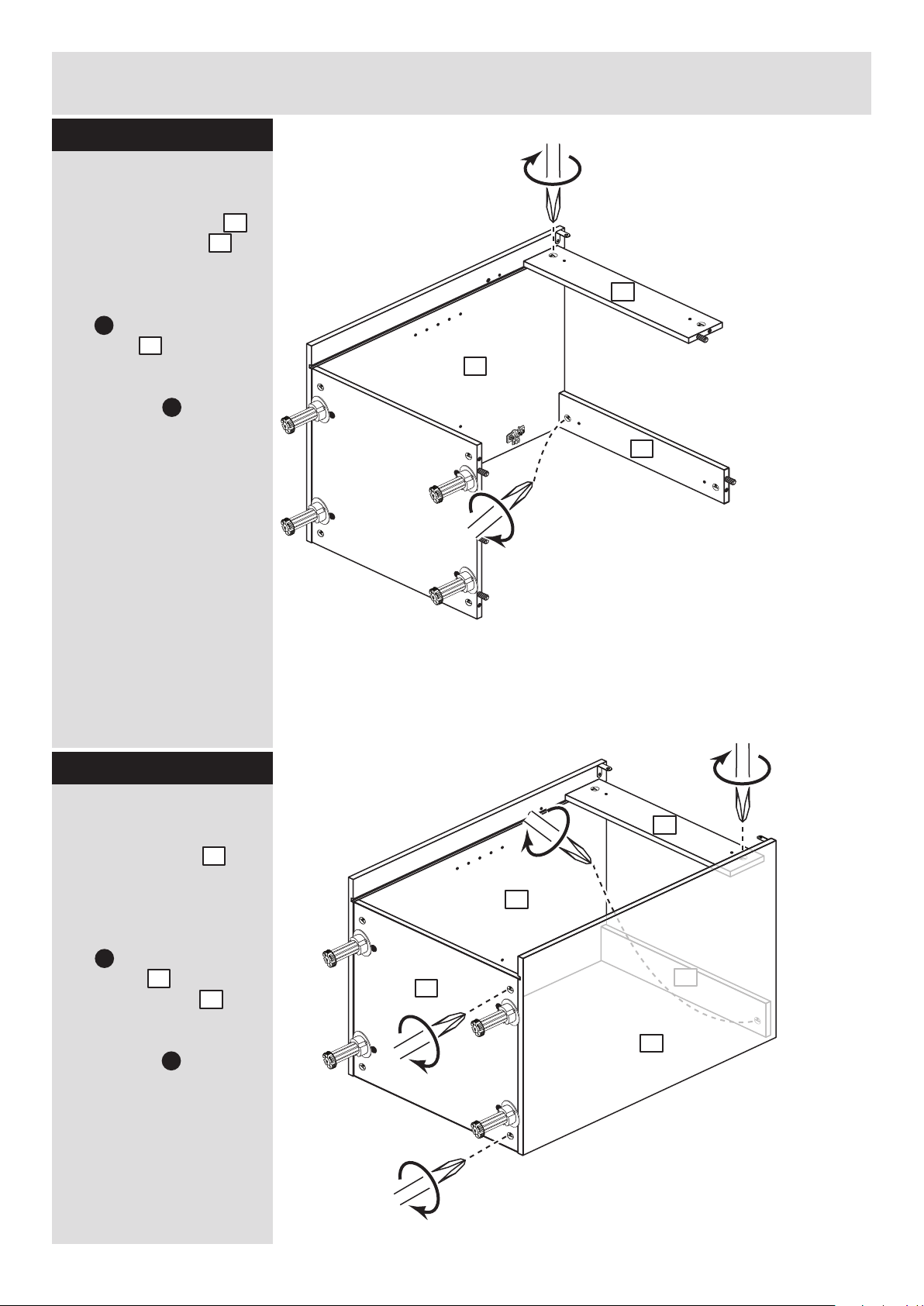
Prepare the 2 cross
rails
Insert 2 large locking
nuts into the cross
rails as shown.
Tap 2 wooden dowels
into the cross rails as
shown.
4
4
A
Finished
front edge
Join the right side and
base
Push the base onto
the right side .
Use a screwdriver to
tighten the 2 large
locking nuts fitted to
the base .
Note: Turn the large
locking nuts as far as
they will go - more than
1/2 a turn.
B
F
2
3
3
3
2
C
C
Page 46

Assembly Instructions
9
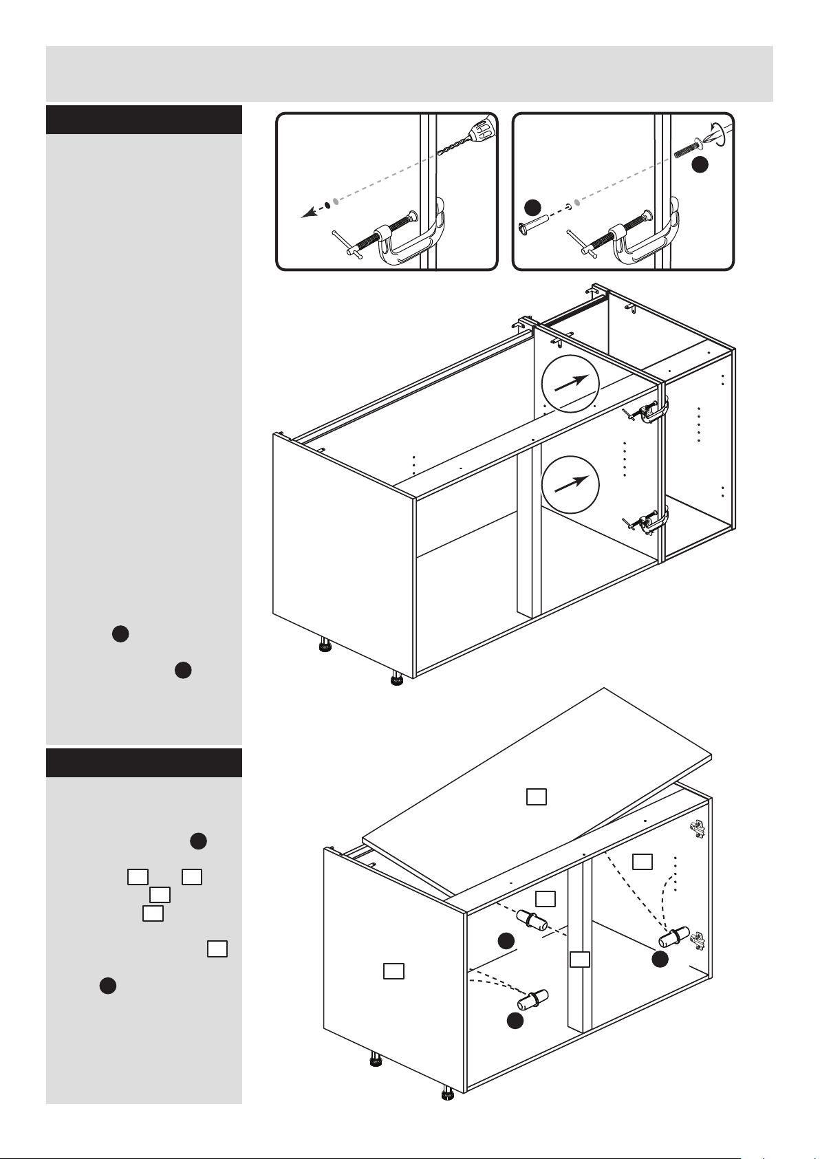
Step 11
4
Fit the 2 cross rails
Push each cross rail
onto the right side .
Use a screwdriver to
tighten the large locking
nut fitted to each
cross rail .
Note: Turn the large
locking nuts as far as
they will go - more than
1/2 a turn.
2
C
C
4
R
R
R
R
R
R
R
R
2
4
4
Support this cross rail
until the left side has been
fitted in the next step.
R
R
R
R
R
R
R
R
1
4
Step 12
Fit the left side
Push the left side
onto the assembly.
Use a screwdriver to
tighten the large locking
nut fitted to the 2
cross rails and the 2
fitted to the base .
Note: Turn the large
locking nuts as far as
they will go - more than
1/2 a turn.
3
3
1
C
C
4
4
Page 47

Assembly Instructions
10
Step 13
Step 14
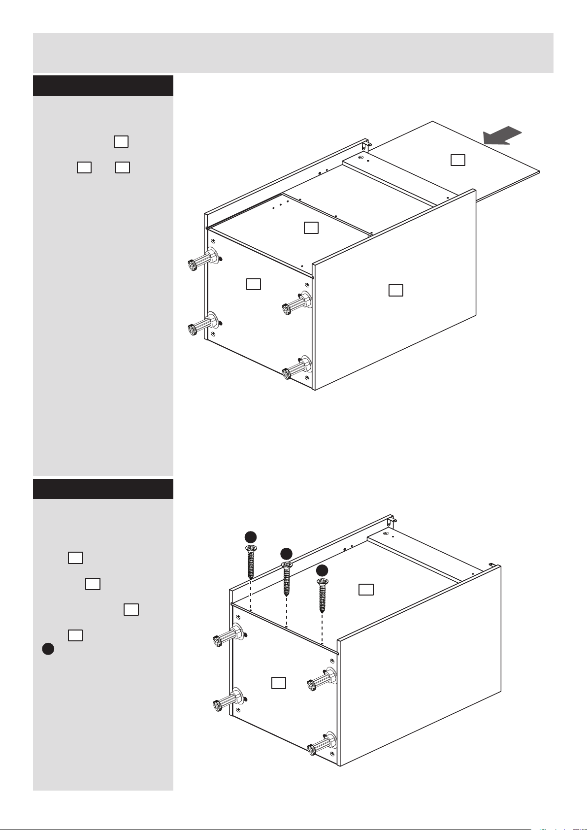
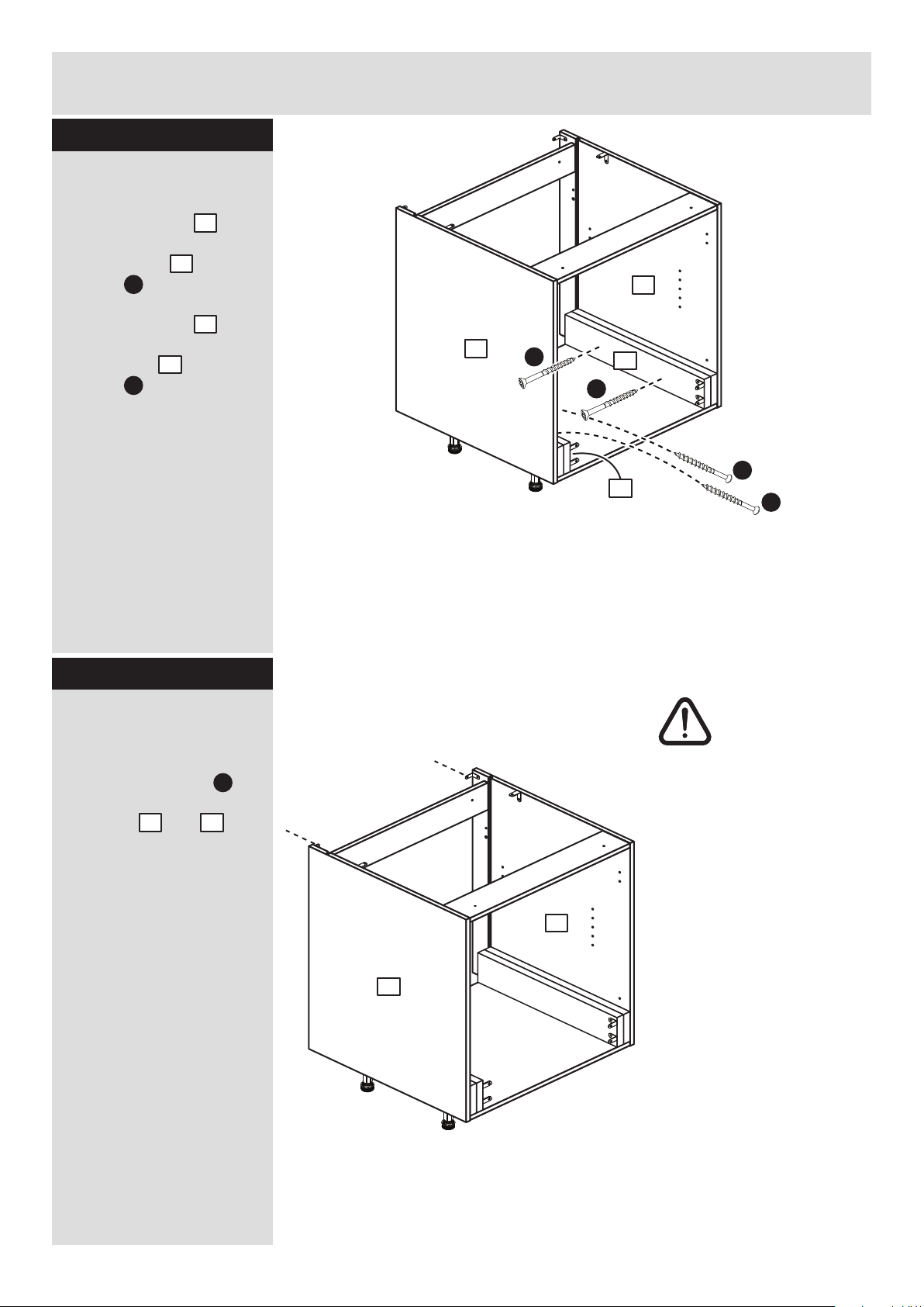
Fit the back
Slide the back along
the grooves in the side
panels and .
7
1 2
R
R
R
R
R
R
R
R
7
1
3
2
R
R
R
R
R
R
R
R
3
F
F
F
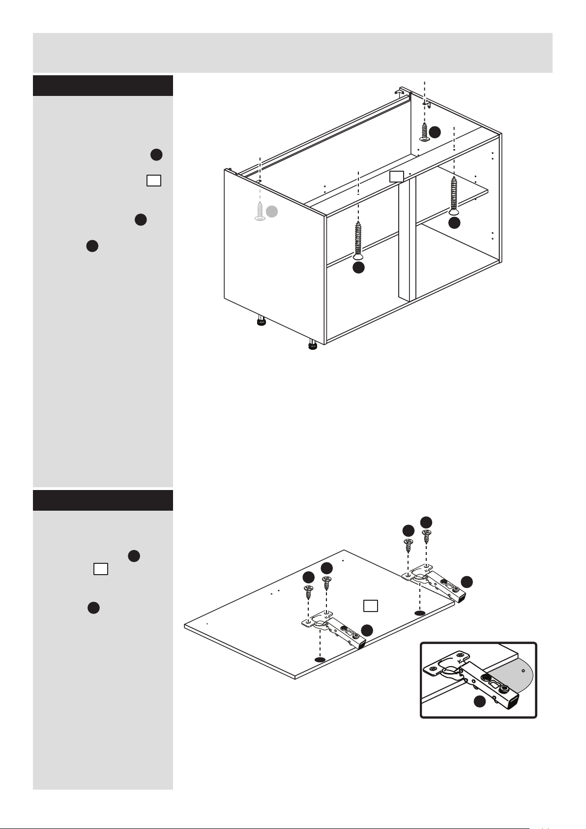
Secure the back
The bottom edge of the
back must be flush
with the bottom edge of
the base .
Secure the back to
the back edge of the
base using 3 screws
. .
Stand the unit up for
the next stage.
7
7
3
3
F
7
Page 48
Assembly Instructions
11
Step 15
Step 16
R
R
R
R
R
Secure the unit to the
wall
Using the brackets
fitted to the back edge of
the sides and
screw the unit to the
wall.
Fixings are not supplied
as they will need to suit
the wall type, and the
length of screw will
depend on the distance
of the back of the Unit to
the wall.
F
5mm
Warning: Take
care when
drilling the wall
that you do not
drill into any pipes, wires
etc. If in doubt, consult
an expert.
Joining units together
Fittings have been
supplied so you are able
to join units together.
Make sure that your first
unit is level.
Push the other unit up
against first unit and
ensure both units are
level.
Check that the ends are
flush and in line, then
clamp them together.
Using a 5mm drill bit,
drill 2 holes (approximate
positions shown circled)
in the side panel into the
adjoining side panel of
the other unit.
Push the connecting
sleeves into the holes
and then screw the
connecting bolts in
from the other side.
G
H
G
H
1 2
R
R
1
2
R
R
R
R
R
R
R
R
R
Page 49
Assembly Instructions
12
Step 17
Step 18
Drill the handle holes
in the drawer fronts
Lay the drawer front
down onto a soft,
smooth surface.
Note: We recommend
the use of a small piece
of waste wood, placed
behind the hole while
drilling, to reduce the
possibility of any
breakout.
Using the pilot holes in
the rear face of the
drawer front , drill
through the holes using a
2.5mm diameter drill.
Turn the drawer front
over and open out the
2.5mm holes that you
have just drilled by
drilling back through
them with a 5mm drill.
Note: Drill bits are not
provided.
Fit the unit to worktop
To fit the unit to the
worktop use 2 screws
to screw up through the
holes in the cross rail
as shown.
Then use 2 screws to
screw up through the
brackets as shown.
F
E
J
4
R
R
R
R
R
R
R
F
F
E
E
8
R
ONLY drill
these 2 holes
Small piece of
waste wood
8
8
8
x 4
Page 50

Assembly Instructions
13
Step 19
Step 20
Step 21
Prepare the drawers
Fit the left drawer side
and right side drawer
side onto the drawer
front using 4 screws
. into the slotted holes.
Important: Make sure
that the drawer sides
and drawer front are the
correct way around.
D
D
D
D
S
S
Top of
drawer
front
Wheel on
outside
surface
Wheel on
outside
surface
R
R
8
8
D
Fit the drawer base
Push the drawer base
against the bottom of the
drawer sides and .
While holding it in place,
secure the drawer base
. using 4 screws
into the front and back
holes, as shown.
D
D
D
D
S
R
6
6
6
R S
D
x 4
Fit the drawer back
Push the drawer back
up into the drawer
assembly.
While holding it in place,
secure the drawer back
. using 4 screws
into the top and bottom
holes, as shown.
D
D
D
D
5
5
5
D
x 4
x 4
Page 51

Assembly Instructions
Step 22
Step 23
14
Fit the soft close
catches
Position the location hole
of the right soft close
catch marked ‘R’ into
the 3rd hole up from the
front of the right drawer
side then secure
using 3 screws .
Position the location hole
of the left soft close
catch marked ‘L’ into
the 3rd hole up from the
front of the left drawer
side and secure using
3 screws .
L
R
O
O
M
O
S
R
M
S
R
D
M
D
D
D
D
Location
hole
D
D
D
Location
hole
x 4
Fit the handle
Attach the handle
supplied with the drawer
front using the
screw(s) packed
with it.
T b
T b
T a
8
T a
8
T b
Page 52

Assembly Instructions
15
Step 24
Step 25
L N
R
R
R
R
R
R
R
R
R
Prepare the soft close
units
Before fitting the drawers
you will need to push the
movable part of the 8
soft close units and
forward until it clicks into
place.
NL
R
and
NL
and
R
R
R
R
R
R
R
R
Fit the drawers
Slide the wheels on the
drawer sides and
over the wheels on the
runners and then
push the drawer into
position.
Important: Make sure
that 2 soft close catches
on each drawer engage
with the soft close units
fitted to the side panels.
P Q
R S
and
and
R S
P Q
Page 53

Assembly Instructions
16
If you need help or have damaged or missing parts, call the Customer Helpline: 08456 400800
and quote the reference numbers on the component pages.
Argos Ltd, 489-499 Avebury Boulevard, Central Milton Keynes, MK9 2NW
Step 26
Fit other products to
the unit
To fit other products to
this unit e.g. worktops
etc., please follow the
instructions packed with
them.
We recommend that you
consult a qualified joiner
or kitchen fitter.
Assembly is complete
Warning: The
unit is heavy.
Lift with care.
R
Fit the plinth
After cutting the plinth to
the required length, offer
the plinth up to the unit
and using a pencil, mark
the position of the unit’s
legs on the back of
the plinth.
Position the leg bracket
. so it is in the centre
of the pencil mark and
half way up the plinth.
Fix the leg bracket
to the back of the plinth
using 2 screws .
Slide the leg clip
into the leg bracket
Offer the plinth up to the
unit and push the leg
clips onto the legs
. .
I b
I b
I c
I c
I c
I d
I d
.
I e
Pencil mark
Plinth
I c
I c
I d
Plinth
I e I e
Step 27
608/2345
608/2369
205/5668
198/9917
608/2352
Black Plinth Pack
Cream Plinth Pack
Oak Plinth Pack
White HN Plinth Pack
White Gloss Plinth Pack
Page 54

Page 55

Page 56

ALR2654
Page 57

MADE IN
BRITAIN
Dimensions
Width - 60cm
Depth - 59cm
Height - 87cm
Valencia - Under Oven Cabinet
Assembly Instructions - Please keep for future reference
If you need help or have damaged or missing parts, call the Customer Helpline: 08456 400800
Issue 2 - 05/08/14
Important - Please read these instructions fully before starting assembly
hygena
656/5831
656/6720
656/6744
205/4281
656/6737
203/8104
Cabinet
Black Door Pack
Cream Door Pack
Oak Door Pack
White Gloss Door Pack
White HN Door Pack
Page 58

Safety and Care Advice
Important - Please read these instructions fully before starting assembly
• Warning: This unit weighs
approximately 16.5kgs.
Please lift with care.
• Check you have all the
components and tools listed on
pages 2, 3 and 4.
• Remove all fittings from the
plastic bags and separate them
into their groups.
• Keep children and animals
away from the work area, small
parts could choke if swallowed.
• Parts of the assembly will be
easier with 2 people.
• Make sure you have enough
space to layout the parts before
starting.
• Do not stand or put weight on
the product, this could cause
damage.
• Assemble the item as close to
its final position (in the same
room) as possible.
• Assemble on a soft level
surface to avoid damaging the
unit or your floor (use opened
out unit carton).
1
Care and maintenance
• Only clean using a damp cloth
and mild detergent, do no use
bleach or abrasive cleaners.
• From time to time check that
there are no loose screws on
this unit.
• This product should not be
discarded with household
waste. Take to your local
authority waste disposal centre.
Note: If required the next page
can be cut out and used as
reference throughout the
assembly. Keep this page with
these instructions for future
reference.
• We do not
recommend the
use of power
drill/drivers for
inserting screws,
as this could damage the unit.
Only use hand screwdrivers.
• Safety note: It is
recommended that this unit is
secured to a wall using the
brackets supplied.
• Dispose of all packaging
carefully and responsibly.
Page 59

Components - Panels
Please check you have all the panels listed below
2
1
If you have damaged or missing components, call the
Customer Helpline: 08456 400800 quoting the reference
numbers below
2
4
3
Left Side (DPF068A)
(720 x 560mm)
Right Side (DPF069A)
(720 x 560mm)
Base (DPF078A)
(569 x 494mm)
Cross Rail (DPF080A)
(569 x 96mm) x 2
5
Support Rail (DPF112A)
(495 x 105mm) x 4
The front surface of this fascia
is protected with a peel-off film
Appliance Fascia (DPF124B)
(596 x 120mm)
6
Page 60

Please check you have all the fittings listed below
3
Components - Fittings
If you have damaged or missing components, call the
Customer Helpline: 08456 400800 quoting the reference
numbers below
Tools required
Note: The quantities below are the correct amount to complete the assembly. In some cases
more fittings may be supplied than are required.
A
Wooden dowel (F22) x 10
B
Metal dowel (F901) x 8
C
D
Large locking
nut (F900) x 8
G H
K
I a
I c
I d
I e
I b
Rule Scissors Hammer
Eye protection
(when using a
hammer or drill)
Cross-head
screwdriver
Ruler - Use this ruler to help correctly identify the screws
mm 10 20 30 40 50 60 70 80 90 100 110 120 130 140 150 160 170
J
Electric drill
E
13mm Screw (F79) x 14
Connecting Sleeve (F432) x 2 19mm Connecting bolt (F461) x 2
Bracket (F945) x 8
Leg Bracket
(F127) x 2
Leg Socket
(F120) x 4
Leg Clip
(F128) x 2
16mm Screw
(F129) x 16
Leg (F122) x 4
45mm Screw (F65) x 4
F
25mm Screw (F50) x 2
38mm Screw (F933) x 4
Page 61

Assembly Instructions
4
If you have damaged or missing components, call the
Customer Helpline: 08456 400800 quoting the reference
numbers below
Step 1
B
B
J
J
J
E
1
B
J
E
5mm
150mm
B
B
B
1st 5mm hole
2nd 5mm hole
1
Prepare the left side
Screw a metal dowel
into one of the holes
shown on the left side
. .
Note: Tighten metal
dowels up fully against
the panels.
Important: The position
of the metal dowel
depends on where you
would like the cross rail
to be.
B
1
B
The hole chosen for the metal
dowel determines the position of
the rear cross rail.
This will depend on where the
services to the oven will be located.
We recommend that you consult a
qualified joiner or kitchen fitter.
Step 2
Prepare the left side
Screw 3 metal dowels
into the holes shown on
the left side .
Note: Tighten metal
dowels up fully against
the panels.
Fit a bracket flush to
the top edge of the left
side , about 150mm
in from the groove, see
diagram.
Secure the bracket
using screw .
Fit another bracket
flush to the back edge of
the left side , about
5mm down from the top
edge, see diagram.
Secure the bracket
using screw .
Note: The brackets must
be flush with the
top/back edge of the
panel.
B
1
J
J
1
J
1
E
J
E
Only screw ONE metal dowel into
one of these holes.
Page 62

Assembly Instructions
5
Step 3
Step 4
Prepare the right side
Screw 3 metal dowels
into the holes shown on
the right side .
Fit a bracket flush to
the top edge of the right
side , about 150mm
in from the groove, see
diagram.
Secure the bracket
using screw .
Fit another bracket
flush to the back edge of
the right side , about
5mm down from the top
edge, see diagram.
Secure the bracket
using screw .
B
2
J
J
2
J
2
E
J
E
J
E
B
B
B
J
J
2
J
E
Prepare the right side
Screw a metal dowel
into one of the holes
shown on the right side
. .
Use the same hole that
you used for the left side
in step 1.
B
B
2
2
Only screw ONE metal dowel
into one of these holes (use
the same hole that you used
for the left side in step 1).
Page 63

Assembly Instructions
6
Step 5
Step 6
I a I a
I b
b: c: d:
Fit the legs to the
base
a: Push the leg sockets
. into the holes in the
base as shown.
b: Secure each leg
socket with 3
screws .
c: Tap in the centre plug
on each leg socket .
d: Push the leg into
the leg socket .
I a
I a
I a
I e
I e
3
x 3
I a
I a
I b
I a
I a
I a
I a
3
A
A
Prepare the base
Insert 4 large locking
nuts into the base
as shown.
Note: Arrow on locking
nut must point towards
hole in edge of panel.
Tap 6 wooden dowels
into the base as
shown.
Note: Wooden dowels
must not stick out from
the edge by more than
10mm or they may
damage other panels.
C
C
3
10mm
A
A
3
A
A
A
C
C
C
C
A
3
Page 64

Assembly Instructions
7
Step 7
4
Fit the 2 cross rails
Push each cross rail
onto the right side .
Use a screwdriver to
tighten the large locking
nut fitted to each
cross rail .
Note: Turn the large
locking nuts as far as
they will go - more than
1/2 a turn.
2
C
C
4
2
4
4
Support the rear cross rail
until the left side has been
fitted in the next step.
Finished
front edge
Step 8
A
C
Prepare the 2 cross
rails
Insert 2 large locking
nuts into the cross
rails as shown.
Tap 2 wooden dowels
into the cross rails as
shown.
Step 9
4
4
A
Join the right side and
base
Push the base onto
the right side .
Use a screwdriver to
tighten the 2 large
locking nuts fitted to
the base .
Note: Turn the large
locking nuts as far as
they will go - more than
1/2 a turn.
B
F
3
3
2
C
C
2
3
A
C
C
4
You may have
selected to fit the
rear cross rail here
(refer back to step 1).
Page 65

Assembly Instructions
8
Step 10
Step 11
Fit 2 support rails
Fit a support rail to
the right side using 2
screws .
Fit a support rail to
the left side using 2
screws .
Note: The support rails
must be flush with the
front of the unit.
Step 12
Prepare the other 2
support rails
Fit 2 brackets flush to
one end of the remaing
support rails using
screw .
Fit the left side
Push the left side
onto the assembly.
Use a screwdriver to
tighten the large locking
nut fitted to the 2
cross rails and the 2
fitted to the base .
Note: Turn the large
locking nuts as far as
they will go - more than
1/2 a turn.
3
1
C
C
4
4
1
4
3
1
2
K
K
K
K
5
5
5
1
2
K
5
K
J
J
J
E
E
J
J
E
E
5
5
E
Page 66
Assembly Instructions
9
Step 13
Step 14
Fit 2 support rails
Fit a support rail flush
with the support rail on
the right side using 2
screws .
Fit a support rail flush
with the support rail on
the left side using 2
screws .
D
D
1
2
5
1
2
D
5
D
Warning: Take
care when
drilling the wall
that you do not
drill into any pipes, wires
etc. If in doubt, consult
an expert.
1
2
D
D
5
5
Secure the unit to the
wall
Using the brackets
fitted to the back edge of
the sides and
screw the unit to the
wall.
Fixings are not supplied
as they will need to suit
the wall type, and the
length of screw will
depend on the distance
of the back of the Unit to
the wall.
J
1 2
Page 67

Assembly Instructions
10
Step 15
Step 16
Joining units together
Fittings have been
supplied so you are able
to join units together.
Make sure that your first
unit is level.
Push the other unit up
against first unit and
ensure both units are
level.
Check that the ends are
flush and in line, then
clamp them together.
Using a 5mm drill bit,
drill 2 holes (approximate
positions shown circled)
in the side panel into the
adjoining side panel of
the other unit.
Push the connecting
sleeves into the holes
and then screw the
connecting bolts in
from the other side.
G
H
Fit the unit to worktop
To fit the unit to the
worktop use 2 screws
to screw up through the
holes in the cross rail
as shown.
Then use 2 screws to
screw up through the
brackets as shown.
F
E
J
4
F
F
E
E
4
5mm
G
H
Page 68

Assembly Instructions
11
Step 17
Step 18
Fit the appliance
fascia
Offer the appliance
fascia up to the unit,
so that it is flush with the
bottom and sides of the
unit.
Use 2 screws to
screw through the
brackets fitted to the
support rails and into
the back surface of the
appliance fascia .
6
E
J
5
5
6
6
E
E
5
E
E
Pencil mark
Plinth
I c
I c
I d
Plinth
I e I e
Fit the plinth
After cutting the plinth to
the required length, offer
the plinth up to the unit
and using a pencil, mark
the position of the unit’s
legs on the back of
the plinth.
Position the leg bracket
. so it is in the centre
of the pencil mark and
half way up the plinth.
Fix the leg bracket
to the back of the plinth
using 2 screws .
Slide the leg clip
into the leg bracket
Offer the plinth up to the
unit and push the leg
clips onto the legs
. .
I b
I b
I c
I c
I c
I d
I d
.
I e
608/2345
608/2369
205/5668
198/9917
608/2352
Black Plinth Pack
Cream Plinth Pack
Oak Plinth Pack
White HN Plinth Pack
White Gloss Plinth Pack
Page 69

Assembly Instructions
13
If you need help or have damaged or missing parts, call the Customer Helpline: 08456 400800
and quote the reference numbers on the component pages.
Argos Ltd, 489-499 Avebury Boulevard, Central Milton Keynes, MK9 2NW
Step 19
Fit other products to
the unit
To fit other products to
this unit e.g. worktops
etc., please follow the
instructions packed with
them.
We recommend that you
consult a qualified joiner
or kitchen fitter.
Assembly is complete
Warning: The
unit is heavy.
Lift with care.
Install the oven
Please refer to the
instructions that were
supplied with the oven.
We recommend that
you contact a
registered installer.
Step 20
Page 70

Page 71

Page 72

ALR2659
Page 73

MADE IN
BRITAIN
Cabinet
Black Door Pack
Cream Door Pack
Grey Door Pack
Plum Door Pack
White Door Pack
Dimensions
Width - 50cm
Depth - 34cm
Height - 72cm
Valencia - 500mm Wall Cabinet
Assembly Instructions - Please keep for future reference
If you need help or have damaged or missing parts, call the Customer Helpline: 08456 400800
Issue 1 - 17/08/11
Important - Please read these instructions fully before starting assembly
hygena
656/5721
633/2882
633/2710
656/5295
656/4540
633/2806
Page 74

Safety and Care Advice
Important - Please read these instructions fully before starting assembly
• Warning: This unit weighs
approximately 10kgs.
Please lift with care.
• Check you have all the
components and tools listed on
pages 1, 2 and 3.
• Remove all fittings from the
plastic bags and separate them
into their groups.
• Keep children and animals
away from the work area, small
parts could choke if swallowed.
• Parts of the assembly will be
easier with 2 people.
• Make sure you have enough
space to layout the parts before
starting.
• Do not stand or put weight on
the product, this could cause
damage.
• Assemble the item as close to
its final position (in the same
room) as possible.
• Assemble on a soft level
surface to avoid damaging the
unit or your floor (use opened
out unit carton).
1
Care and maintenance
• Only clean using a damp cloth
and mild detergent, do no use
bleach or abrasive cleaners.
• From time to time check that
there are no loose screws on
this unit.
• This product should not be
discarded with household
waste. Take to your local
authority waste disposal centre.
Note: If required the next page
can be cut out and used as
reference throughout the
assembly. Keep this page with
these instructions for future
reference.
• We do not
recommend the
use of power
drill/drivers for
inserting screws,
as this could damage the unit.
Only use hand screwdrivers.
• Safety note: It is
recommended that this unit is
secured to a wall using the
brackets supplied.
• Dispose of all packaging
carefully and responsibly.
Tools required
Rule Scissors Hammer
Eye protection
(when using a
hammer or drill)
Cross-head
screwdriver
Electric drill
Page 75
Components - Panels
Please check you have all the panels listed below
2
1
If you have damaged or missing components, call the
Customer Helpline: 08456 400800 quoting the reference
numbers below
3
2
4
End Panel (DPF141A)
(320 x 716 mm) x 2
Loose Shelf (DPF092A)
(468 x 236mm)
Top/Base Panel (DPF091A)
(469 x 319 mm) x 2
5
Back Panel (DPF093A)
(479 x 694 mm)
Valencia Door (DPF147B)
(497 x 716mm)
The front surface
of this door is
protected with a
peel-off film
Page 76

Please check you have all the fittings listed below
3
Components - Fittings
If you have damaged or missing components, call the
Customer Helpline: 08456 400800 quoting the reference
numbers below
Note: The quantities below are the correct amount to complete the assembly. In some cases
more fittings may be supplied than are required.
A
Wooden dowel (F22) x 8
B
Metal dowel (F901) x 8
C
D
Large locking
nut (F900) x 8
F
G H
K
I
Ruler - Use this ruler to help correctly identify the screws
mm 10 20 30 40 50 60 70 80 90 100 110 120 130 140 150 160 170
13mm Screw (F63) x 4
E
19mm Connecting bolt (F461) x 2
M
25mm Screw (F50) x 4
Connecting Sleeve (F432) x 2
Shelf support (F110) x 4
Hinge Cover (F119) x 2
h
ygen
a
J
Wall bracket (F198) x 2
Hanging bracket
(F849) x 2
L
Hinge Arm (F118) x 2
Hinge Plate
(F117) x 2
NNa
b
25mm Screw (F132) x 2
Handle (F214) x 1
Page 77

Assembly Instructions
4
If you have damaged or missing components, call the
Customer Helpline: 08456 400800 quoting the reference
numbers below
Step 1
Choose which way
you would like the
door to open
You can fit the door to
the left side or right side.
If you would like
your door to
open this way,
fit the hinge
plates to the left
end panel
If you would like
your door to
open this way,
fit the hinge
plates to the
right end panel
Step 2
K
Prepare the left end
panel
Refer to step 1 and, if
required, fit 2 hinge
plates onto the left
end panel , orientated
as shown.
Screw 4 metal dowels
into the holes shown on
the left end panel .
Note: Tighten metal
dowels up fully against
the panels.
Fit a hanging bracket
to the left side using
2 screws , making
sure that the hook is
towards the back edge.
1
B
1
B
K
K
B
B
B
B
This will be the
left end panel
1
J
G
G
J
1
G
1
K
Page 78

5
Step 3
Step 4
Prepare the base and
top
Insert 4 large locking
nuts into the base
and top as shown.
Note: Arrow on locking
nut must point towards
hole in edge of panel.
Tap 4 wooden dowels
into the base and top
as shown.
Note: Wooden dowels
must not stick out from
the edge by more than
10mm or they may
damage other panels.
C
C
2
10mm
A
A
2
B
B
B
B
1
This will be the
right end panel
K
Prepare the right end
panel
Refer to step 1 and, if
required, fit 2 hinge
plates onto the right
end panel , orientated
as shown.
Screw 4 metal dowels
into the holes shown on
the right end panel .
Note: Tighten metal
dowels up fully against
the panels.
Fit a hanging bracket
to the right side using
2 screws , making
sure that the hook is
towards the back edge.
1
B
1
J
1
G
J
G
G
K
1
K
K
A
A
C
C
C
AA
A
C
2
A
A
C
C
C
AA
A
C
2
Assembly Instructions
Page 79

Finished
front edge
Assembly Instructions
6
Step 5
Join the right side and
base
Push the base onto
the right end panel .
Use a screwdriver to
tighten the 2 large
locking nuts fitted to
the base .
Note: Turn the large
locking nuts as far as
they will go - more than
1/2 a turn.
B
C
2
2
1
C
C
Step 6
2
1
1
2
Fit the top
Push the top onto
the right end panel .
Use a screwdriver to
tighten the 2 large
locking nuts fitted to
the top .
Note: Turn the large
locking nuts as far as
they will go - more than
1/2 a turn.
2
2
1
C
C
Page 80

Assembly Instructions
7
Step 7
Step 8
Fit the back
Slide the back along
the grooves in the top
and base and into
the groove of the right
end panel .
Important: Make sure
that the cut-outs on the
back are at the top of
the assembly.
2
2
1
4
4
4
2
2
1
C
Fit the left end panel
Push left end panel
onto the assembly.
Use a screwdriver to
tighten the 4 large
locking nuts fitted to
the base and top .
Note: Turn the large
locking nuts as far as
they will go - more than
1/2 a turn.
1
2
2
2
C
1
Cut-outs
at the top
2
Page 81

Assembly Instructions
8
Step 9
I
I
464mm
18mm
37mm
464mm
18mm
I I
Outline of
the unit
To adjust the height of
the unit on the wall,
turn the bottom screw
Pull the unit up
against the wall
by tightening
the top screw
J
I
Warning: The
unit is heavy.
Lift with care.
Fit the unit to the wall
If you are joining this unit
to another one, also refer
to step 10.
To fix the unit to the wall,
place the unit in the
required position and
lightly mark the outline of
the top corners of the
unit with a pencil.
Fit the 2 wall brackets
to the dimensions shown
in the top diagram.
The screws and plugs
are not supplied as they
need to be the correct
type to suit your wall.
Place your unit onto the
wall brackets , via the
hanging brackets
which you have fitted to
the sides of the unit.
Use the screw in the
bottom of the wall
brackets to adjust the
height of the unit.
Finally, pull the unit up
against the wall by
tightening up the top
screw in the hanging
brackets .
Warning: Take
care when
drilling the wall
that you do not drill into
any pipes, wires etc. If in
doubt, consult an expert.
I
I
J
1
J
J
1
1
Page 82

9
Step 10
Assembly Instructions
5mm
Joining units together
Fittings have been
supplied so you are able
to join units together.
Make sure that your first
unit is level.
Push the other unit up
against first unit and
ensure both units are
level.
Check that the ends are
flush and in line, then
clamp them together.
Using a 5mm drill bit,
drill 2 holes (approximate
positions shown circled)
in the side panel into the
adjoining side panel of
the other unit.
Push the connecting
sleeves into the holes
and then screw the
connecting bolts in
from the other side.
E
F
E
F
Page 83

Assembly Instructions
10
Step 11
Step 12
Fit the loose shelf
Insert 4 shelf studs at
the required height.
Lower the loose shelf
down onto the shelf
studs .
H
H
3
H
3
x 4
Prepare the door
Push fit the 2 hinges
into the door .
Secure each hinge with
2 screws .
Note: Before securing
with the screws, make
sure that the hinges are
positioned at 90 degrees
with the front edge of the
door.
D
L
5
5
L
L
90
L
D
D
D
D
Page 84

Assembly Instructions
11
Step 13
Small piece of
waste wood
Drill the handle holes
in the door
Important: Please follow
these instructions
carefully.
Lay the door down
onto a smooth surface.
Important: Carefully
choose which holes you
need to drill.
This will depend on
which side you fitted the
hinge plates .
Check that the holes and
hinges are in the same
place as the diagrams.
Note: We recommend
the use of a small piece
of waste wood, placed
behind the hole while
drilling, to reduce the
possibility of any
breakout.
Using the pilot hole in
the rear face of the door,
. drill through the
holes indicated opposite,
using a 2.5mm diameter
drill.
Turn the door over
and open out the 2.5mm
holes that you have just
drilled by drilling back
through them with a
5mm drill.
Note: Drill bits are not
provided.
5
K
5
5
Small piece of
waste wood
Drill these 2 holes if
you have fitted the
hinges to the left side.
Drill these 2 holes if you
have fitted the hinges
to the right side.
ONLY drill
these 2 holes
or
5
5
ONLY drill
these 2 holes
DO NOT drill
any other holes
DO NOT drill
any other holes
PLEASE FOLLOW THESE INSTRUCTIONS CAREFULLY
TO CHOOSE WHICH 2 HOLES YOU WILL NEED TO DRILL
Page 85
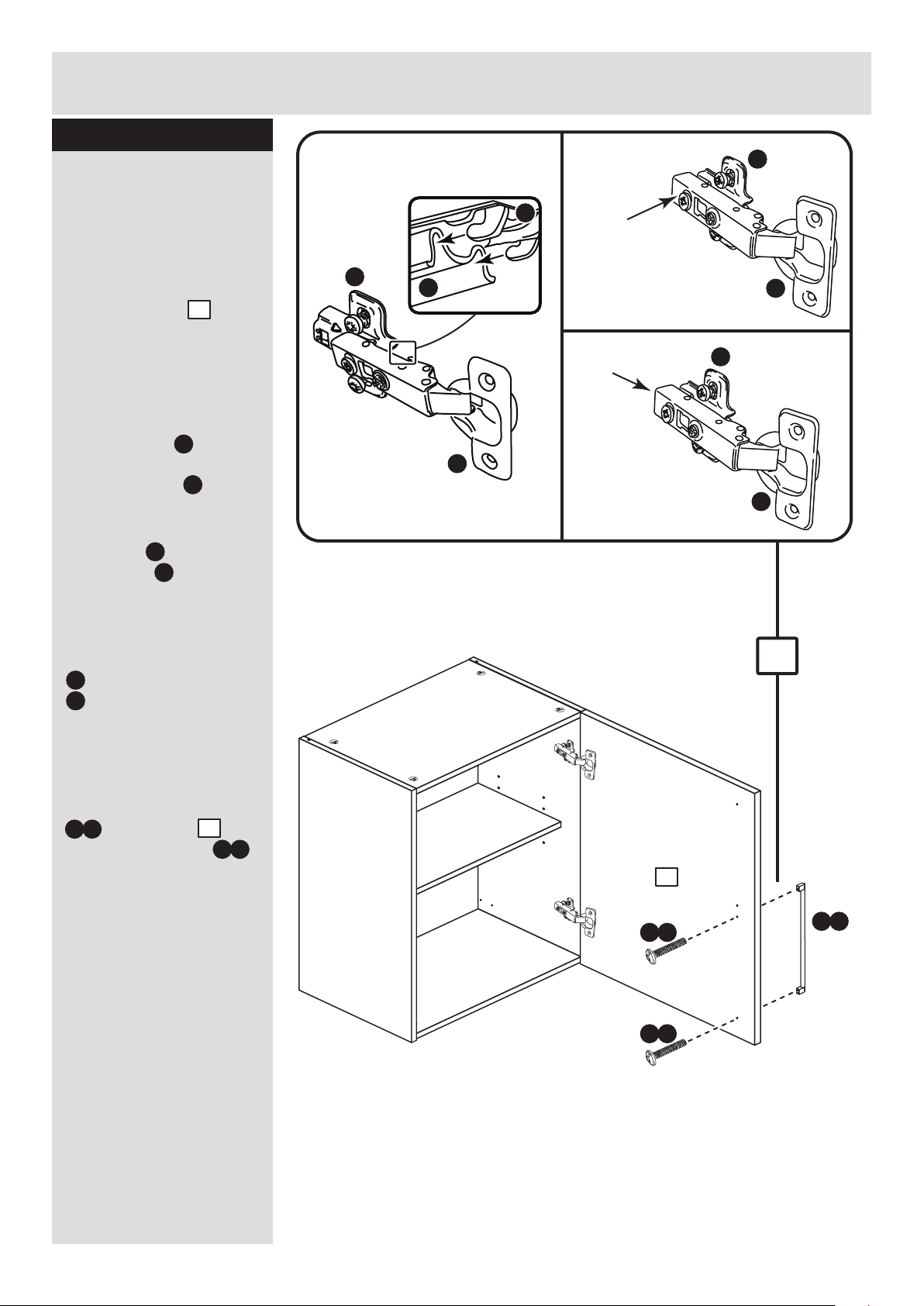
N a
Assembly Instructions
12
Step 14
a:
b:
c:
This shows the door being fitted to hinge
plates on the right side.
You may have fitted them to the left side.
Push and
click
Push
d:
Fit door and handle
2 people are needed
here
Note: The easiest way to
attach the door is to
fit the top hinge first,
then align and fit the
other hinge.
a: Push the hooks on
the hinge arm
underneath the front of
the hinge plate .
b: Press the front of the
hinge arm against the
hinge plate until it
clicks into place.
c: If you need to
seperate the hinge arm
. from the hinge plate,
. press the button at
the end of the hinge arm
and lift it off of the hinge
plate.
d: Attach the handle
. to the door
using the 2 screws
packed with it.
K
L
L
K
K
L
K
L
K
K
L
5
L
K
L
N a
N b
5
5
N b
N b
Page 86

Assembly Instructions
13
Step 15
Adjust the door if
needed
a: Height adjustment.
Loosen screws A on
hinge plates and move
door up or down as
required.
Retighten screw A.
b: Forward and Back
adjustment.
Loosen screw B on hinge
arm and move door in or
out as required.
Retighten screw B.
c: Sideways
adjustment.
To move door ‘out’
loosen screw C.
To move door ‘in’ tighten
screw C
a:
b:
c:
A
A
C
B
Page 87

Assembly Instructions
14
Step 16
Fit the hinge covers
Push the hinge covers
onto the hinge arms .
M
L
h
ygen
a
M
L
Page 88

Assembly Instructions
15
If you need help or have damaged or missing parts, call the Customer Helpline: 08456 400800
and quote the reference numbers on the component pages.
Argos Ltd, 489-499 Avebury Boulevard, Central Milton Keynes, MK9 2NW
Step 17
ALR2661
Fit other products to
the unit
To fit other products to
this unit, please follow
the instructions packed
with them.
We recommend that you
consult a qualified joiner
or kitchen fitter.
Assembly is complete
Warning: The
unit is heavy.
Lift with care.
Page 89

MADE IN
BRITAIN
Cabinet
Black Door Pack
Cream Door Pack
Grey Door Pack
Plum Door Pack
White Door Pack
Dimensions
Width - 100cm
Depth - 34cm
Height - 72cm
Valencia - 1000mm Wall Cabinet
Assembly Instructions - Please keep for future reference
If you need help or have damaged or missing parts, call the Customer Helpline: 08456 400800
Issue 2 - 15/09/11
Important - Please read these instructions fully before starting assembly
hygena
656/5745
633/2882
633/2710
656/5295
656/4540
633/2806
Page 90

Safety and Care Advice
Important - Please read these instructions fully before starting assembly
• Warning: This unit weighs
approximately 16.5kgs.
Please lift with care.
• Check you have all the
components and tools listed on
pages 1, 2 and 3.
• Remove all fittings from the
plastic bags and separate them
into their groups.
• Keep children and animals
away from the work area, small
parts could choke if swallowed.
• Parts of the assembly will be
easier with 2 people.
• Make sure you have enough
space to layout the parts before
starting.
• Do not stand or put weight on
the product, this could cause
damage.
• Assemble the item as close to
its final position (in the same
room) as possible.
• Assemble on a soft level
surface to avoid damaging the
unit or your floor (use opened
out unit carton).
1
Care and maintenance
• Only clean using a damp cloth
and mild detergent, do no use
bleach or abrasive cleaners.
• From time to time check that
there are no loose screws on
this unit.
• This product should not be
discarded with household
waste. Take to your local
authority waste disposal centre.
Note: If required the next page
can be cut out and used as
reference throughout the
assembly. Keep this page with
these instructions for future
reference.
• We do not
recommend the
use of power
drill/drivers for
inserting screws,
as this could damage the unit.
Only use hand screwdrivers.
• Safety note: It is
recommended that this unit is
secured to a wall using the
brackets supplied.
• Dispose of all packaging
carefully and responsibly.
Tools required
Rule Scissors Hammer
Eye protection
(when using a
hammer or drill)
Cross-head
screwdriver
Electric drill
Page 91

Components - Panels
Please check you have all the panels listed below
2
1
If you have damaged or missing components, call the
Customer Helpline: 08456 400800 quoting the reference
numbers below
3
2
End Panel (DPF141A)
(320 x 716mm) x 2
5
Loose Shelf (DPF098A)
(968 x 236mm)
4
Top/Base Panel (DPF097A)
(969 x 319mm) x 2
Back Panel (DPF099A)
(979 x 694mm)
Muntin Rail (DPF100A)
(36 x 688mm)
6
Valencia Door (DPF147A)
(497 x 716mm) x 2
The front surface
of this door is
protected with a
peel-off film
Page 92

Please check you have all the fittings listed below
3
Components - Fittings
If you have damaged or missing components, call the
Customer Helpline: 08456 400800 quoting the reference
numbers below
Note: The quantities below are the correct amount to complete the assembly. In some cases
more fittings may be supplied than are required.
A
Wooden dowel (F22) x 10
B
Metal dowel (F901) x 8
C
D
Large locking
nut (F900) x 8
F
G H
K
I
N
Ruler - Use this ruler to help correctly identify the screws
mm 10 20 30 40 50 60 70 80 90 100 110 120 130 140 150 160 170
13mm Screw (F63) x 8
E
19mm Connecting bolt (F461) x 2
M
25mm Screw (F50) x 4
Connecting Sleeve (F432) x 2
Shelf support (F110) x 5
Hinge Cover (F119) x 4
h
ygen
a
J
Wall bracket (F198) x 2
Hanging bracket
(F849) x 2
L
Hinge Arm (F118) x 4
Hinge Plate
(F117) x 4
40mm Screw (F910) x 2
OOa
b
25mm Screw (F132) x 4
Handle (F214) x 2
Page 93

Assembly Instructions
4
If you have damaged or missing components, call the
Customer Helpline: 08456 400800 quoting the reference
numbers below
Step 1
K
Prepare the left end
panel
Fit 2 hinge plates onto
the left end panel ,
orientated as shown.
Screw 4 metal dowels
into the holes shown on
the left end panel .
Note: Tighten metal
dowels up fully against
the panels.
Fit a hanging bracket
to the left side using
2 screws , making
sure that the hook is
towards the back edge.
Step 2
1
B
1
B
K
K
B
B
B
B
This will be the
left end panel
1
J
G
G
J
1
G
1
K
B
B
B
B
1
This will be the
right end panel
K
Prepare the right end
panel
Fit 2 hinge plates onto
the right end panel ,
orientated as shown.
Screw 4 metal dowels
into the holes shown on
the right end panel .
Note: Tighten metal
dowels up fully against
the panels.
Fit a hanging bracket
to the right side using
2 screws , making
sure that the hook is
towards the back edge.
1
B
1
J
1
G
J
G
G
K
1
K
K
Page 94

Assembly Instructions
5
Step 3
Prepare the base and
top
Insert 4 large locking
nuts into the base
and top as shown.
Note: Arrow on locking
nut must point towards
hole in edge of panel.
Tap 4 wooden dowels
into the base and top
as shown.
Note: Wooden dowels
must not stick out from
the edge by more than
10mm or they may
damage other panels.
C
C
2
10mm
A
A
2
A
A
C
C
C
AA
A
C
2
A
A
C
C
C
AA
A
C
2
Page 95

Finished
front edge
Assembly Instructions
6
Step 4
Join the right side and
base
Push the base onto
the right end panel .
Use a screwdriver to
tighten the 2 large
locking nuts fitted to
the base .
Note: Turn the large
locking nuts as far as
they will go - more than
1/2 a turn.
B
C
2
2
1
C
C
Step 5
2
1
1
2
Fit the top
Push the top onto
the right end panel .
Use a screwdriver to
tighten the 2 large
locking nuts fitted to
the top .
Note: Turn the large
locking nuts as far as
they will go - more than
1/2 a turn.
2
2
1
C
C
Page 96

A
Assembly Instructions
7
Step 6
Step 7
2
A
4
Prepare the muntin
rail
Tap 2 wooden dowels
into the muntin rail as
shown.
A
4
N
N
4
2
N
Fit the muntin rail
Attach the muntin rail
to the top and base
. and secure with 2
screws .
2
4
2
Page 97
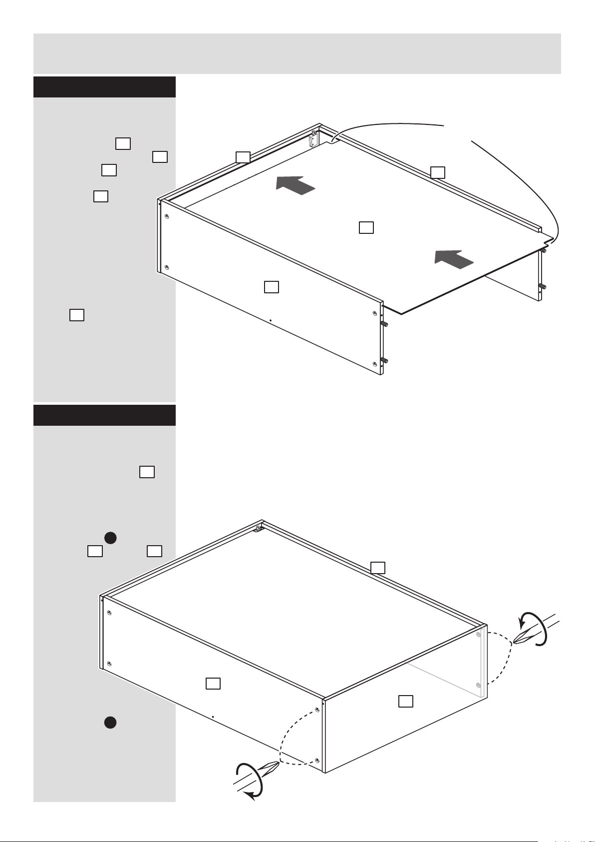
8
Step 8
Assembly Instructions
Step 9
Fit the back
Slide the back along
the grooves in the top
and bottom and into
the groove of the right
end panel .
Important: Make sure
that the cut-outs on the
back are at the top of
the assembly.
2
2
1
5
5
5
2
1
Cut-outs
at the top
C
Fit the left end panel
Push left end panel
onto the assembly.
Use a screwdriver to
tighten the 2 large
locking nuts fitted to
the base and top .
Note: Turn the large
locking nuts as far as
they will go - more than
1/2 a turn.
1
2
2
2
2
C
1
2
Page 98

I
I
964mm
Assembly Instructions
9
Step 10
18mm
37mm
964mm
18mm
I I
Outline of
the unit
To adjust the height of
the unit on the wall,
turn the bottom screw
Pull the unit up
against the wall
by tightening
the top screw
J
I
Warning: The
unit is heavy.
Lift with care.
Fit the unit to the wall
If you are joining this unit
to another one, also refer
to step 11.
To fix the unit to the wall,
place the unit in the
required position and
lightly mark the outline of
the top corners of the
unit with a pencil.
Fit the 2 wall brackets
to the dimensions shown
in the top diagram.
The screws and plugs
are not supplied as they
need to be the correct
type to suit your wall.
Place your unit onto the
wall brackets , via the
hanging brackets
which you have fitted to
the sides of the unit.
Use the screw in the
bottom of the wall
brackets to adjust the
height of the unit.
Finally, pull the unit up
against the wall by
tightening up the top
screw in the hanging
brackets .
Warning: Take
care when
drilling the wall
that you do not drill into
any pipes, wires etc. If in
doubt, consult an expert.
I
I
J
1
J
J
1
1
Page 99

Assembly Instructions
10
Step 11
Joining units together
Fittings have been
supplied so you are able
to join units together.
Make sure that your first
unit is level.
Push the other unit up
against first unit and
ensure both units are
level.
Check that the ends are
flush and in line, then
clamp them together.
Using a 5mm drill bit,
drill 2 holes (approximate
positions shown circled)
in the side panel into the
adjoining side panel of
the other unit.
Push the connecting
sleeves into the holes
and then screw the
connecting bolts in
from the other side.
E
F
Fit the shelf studs
Insert 5 shelf studs at
the required height.
H
H
x 2
H
x 2
H
x 1
5mm
E
F
Step 12
Page 100
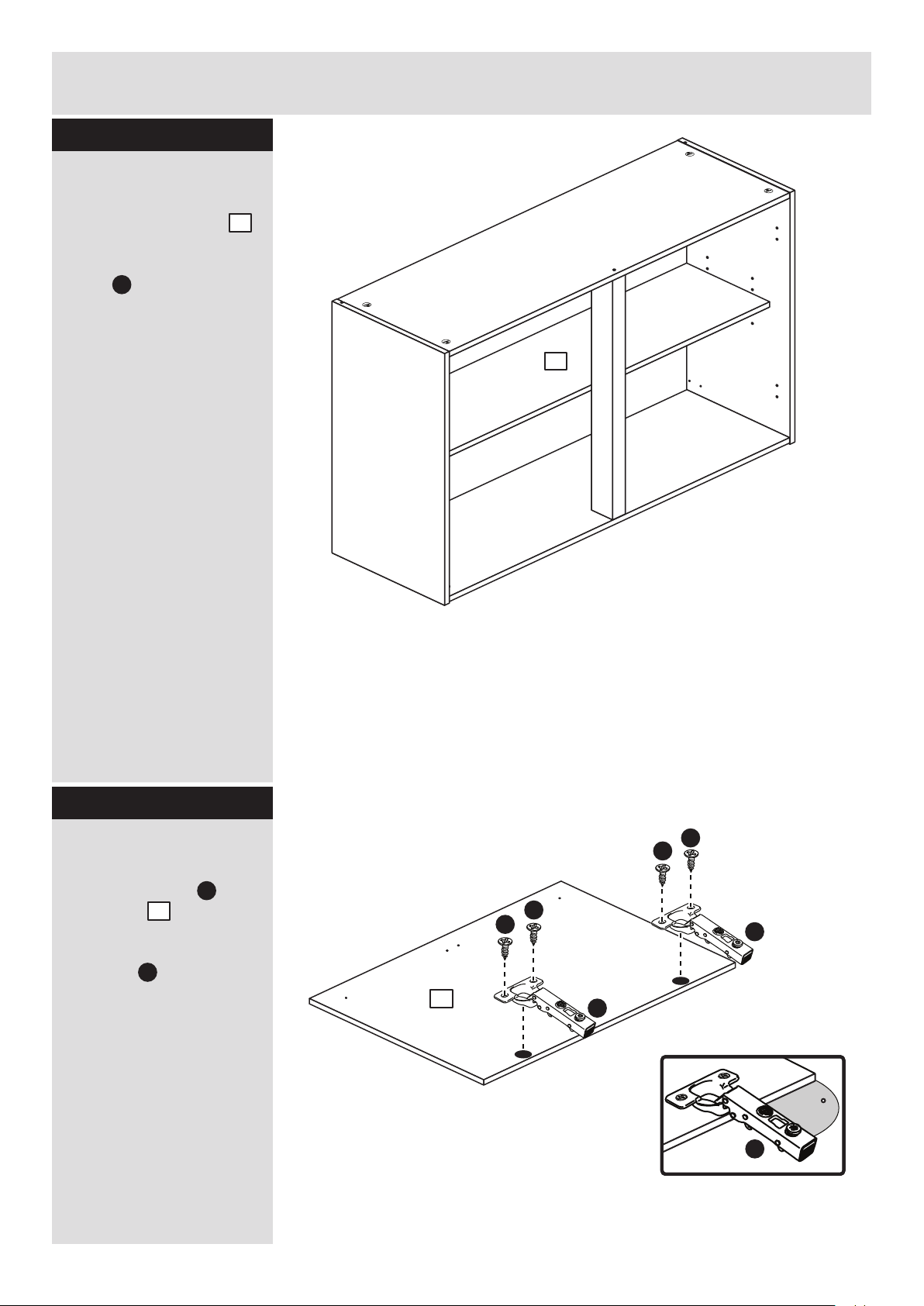
Assembly Instructions
11
Step 13
Fit the loose shelf
Insert the loose shelf
at an angle then lower it
down onto the shelf
studs .
H
3
Step 14
Prepare the doors
Push fit 2 hinges into
each door .
Secure each hinge with
2 screws .
Note: Before securing
with the screws, make
sure that the hinges are
positioned at 90 degrees
with the front edge of the
door.
D
L
6
6
L
L
90
L
D
D
D
D
3
 Loading...