

Page 1
MADE IN
BRITAIN
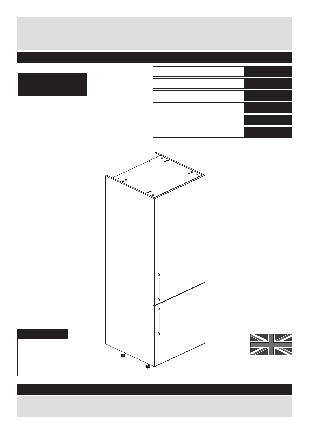
Dimensions
Width - 60cm
Depth - 59cm
Height - 213cm
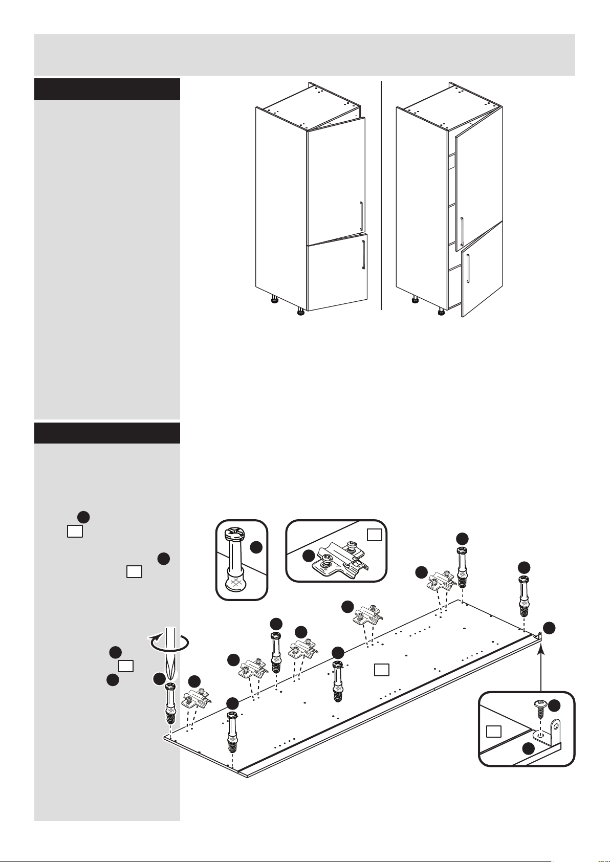
Valencia - 600mm Larder Cabinet
Assembly Instructions - Please keep for future reference
If you need help or have damaged or missing parts, call the Customer Helpline: 08456 400800
Issue 3 - 05/08/14
Important - Please read these instructions fully before starting assembly
hygena
633/7777
633/2923
633/2758
198/9405
633/2844
194/7605
If you are fitting a
Fridge/Freezer inside
this unit please refer to
the instructions that
were supplied with the
appliance.
We recommend that you
contact a registered
installer.
Cabinet
Black Door Pack
Cream Door Pack
Oak Door Pack
White Gloss Door Pack
White HN Door Pack
Page 2
Safety and Care Advice
Important - Please read these instructions fully before starting assembly
• Warning: This unit weighs
approximately 47kgs.
Please lift with care.
• Check you have all the
components and tools listed on
pages 1, 2 and 3.
• Remove all fittings from the
plastic bags and separate them
into their groups.
• Keep children and animals
away from the work area, small
parts could choke if swallowed.
• Parts of the assembly will be
easier with 2 people.
• Make sure you have enough
space to layout the parts before
starting.
• Do not stand or put weight on
the product, this could cause
damage.
• Assemble the item as close to
its final position (in the same
room) as possible.
• Assemble on a soft level
surface to avoid damaging the
unit or your floor (use opened
out unit carton).
1
Care and maintenance
• Only clean using a damp cloth
and mild detergent, do no use
bleach or abrasive cleaners.
• From time to time check that
there are no loose screws on
this unit.
• This product should not be
discarded with household
waste. Take to your local
authority waste disposal centre.
Note: If required the next page
can be cut out and used as
reference throughout the
assembly. Keep this page with
these instructions for future
reference.
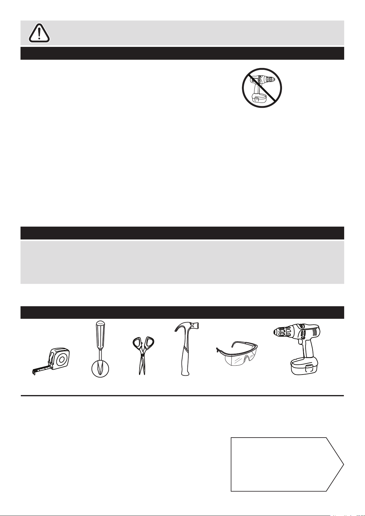
• We do not
recommend the
use of power
drill/drivers for
inserting screws,
as this could damage the unit.
Only use hand screwdrivers.
• Safety note: It is
recommended that this unit is
secured to a wall using the
bracket supplied.
• Dispose of all packaging
carefully and responsibly.
Tools required
Rule Scissors Hammer
Eye protection
(when using a
hammer or drill)
Cross-head
screwdriver
Electric drill
Page 3
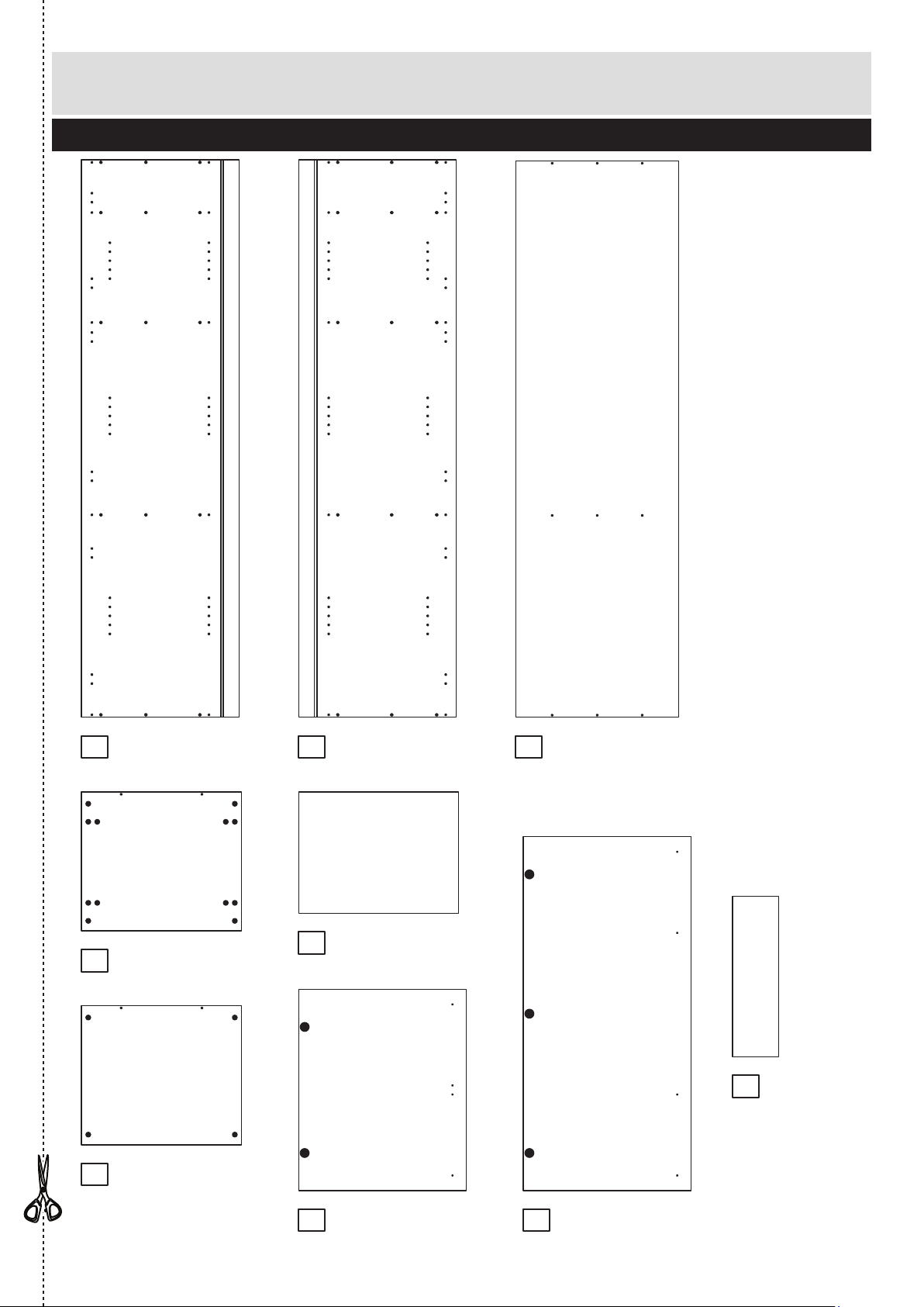
Components - Panels
Please check you have all the panels listed below
2
1
If you have damaged or missing components, call the
Customer Helpline: 08456 400800 quoting the reference
numbers below
2
4
3
5
6
7
Loose Shelf (DPF079A)
(568 x 431mm) x 3
Back (DPF109A)
(579 x 1976mm)
Valencia Door (DPF148B)
(597 x 716mm)
8
Valencia Larder Door (DPF156B)
(597 x 1258mm)
9
Left Side (DPF106B)
(1980 x 560mm)
Right Side (DPF107B)
(1980 x 560mm)
Fixed Shelf (DPF108B)
(569 x 494mm)
Top/Base (DPF078B)
(569 x 494mm) x 2
Small Back
(D1148)
(164.5 x 570mm)
Page 4
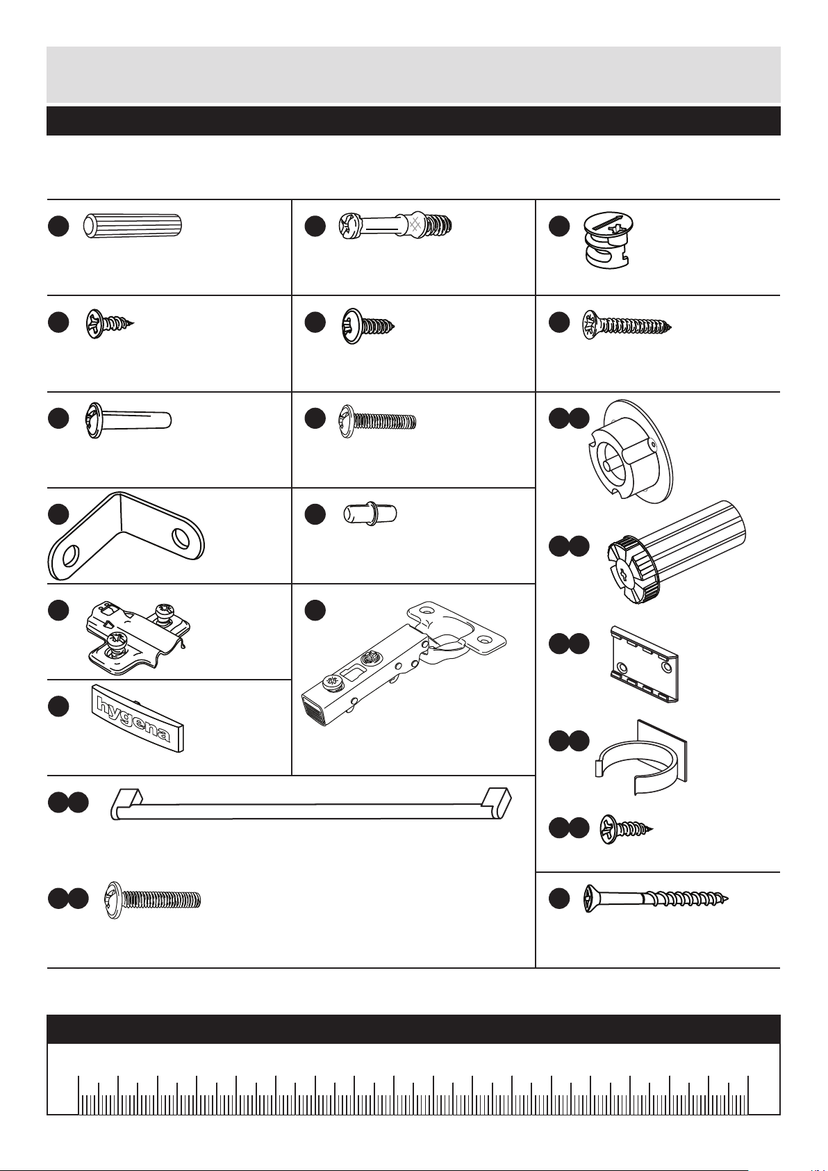
Please check you have all the fittings listed below
3
Components - Fittings
If you have damaged or missing components, call the
Customer Helpline: 08456 400800 quoting the reference
numbers below
Note: The quantities below are the correct amount to complete the assembly. In some cases
more fittings may be supplied than are required.
A
Wooden dowel (F22) x 18
B
Metal dowel (F901) x 12
C
D
Large locking
nut (F900) x 12
F
G H I a
I c
I d
I e
I b
Ruler - Use this ruler to help correctly identify the screws
mm 10 20 30 40 50 60 70 80 90 100 110 120 130 140 150 160 170
J K
13mm Screw (F63) x 10
E
13mm Screw (F79) x 2
Connecting Sleeve (F432) x 2 19mm Connecting bolt (F461) x 2
L M
25mm Screw (F50) x 9
N
Hinge Cover (F119) x 5
Bracket (F945) x 2
Shelf support (F110) x 12
Hinge Plate
(F117) x 5
Hinge Arm (F118) x 5
Leg Bracket
(F127) x 2
Leg Socket
(F120) x 4
Leg Clip
(F128) x 2
16mm Screw
(F129) x 16
Leg (F122) x 4
h
ygen
a
OOa
b
25mm Screw (F132) x 4
Handle (F214) x 2
45mm Screw (F65) x 4
P
Page 5
4
Step 1
J
E
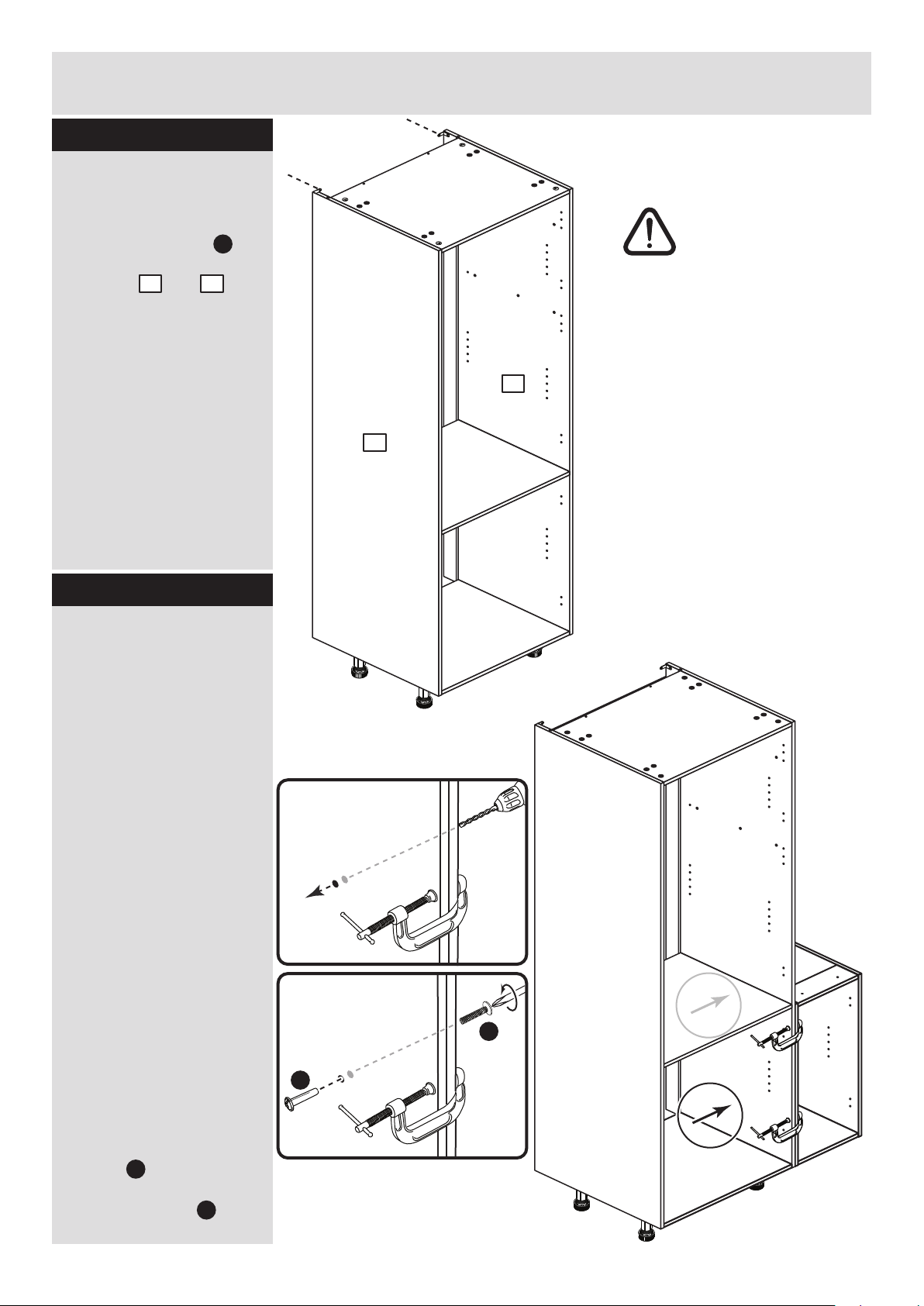
Step 2
Prepare the left side
Refer to step 1 and, if
required, fit 5 hinge
plates onto the left
side , as shown.
Screw 6 metal dowels
into the left side .
Note: Tighten the metal
dowels up fully against
the panels.
Fit a bracket
to the left side
using screw ,
flush with the top
edge and back
edge, see
diagram.
B
B
B
B
B
B
B
B
L
L
L
L
L
J
J
1
1
1
1
1
E
Choose which way
you would like the
doors to open
You can fit the doors to
the left side or right side.
Assembly Instructions
If you have damaged or missing components, call the
Customer Helpline: 08456 400800 quoting the reference
numbers below
1
L
L
If you would
like your doors
to open this
way, fit the
hinge plates to
the left side
If you would
like your doors
to open this
way, fit the
hinge plates to
the right side
IMPORTANT
Only carry out this step if you are building a Larder Cupboard.
If you are building a housing for a fridge/freezer go to Step 3.
Page 6
5
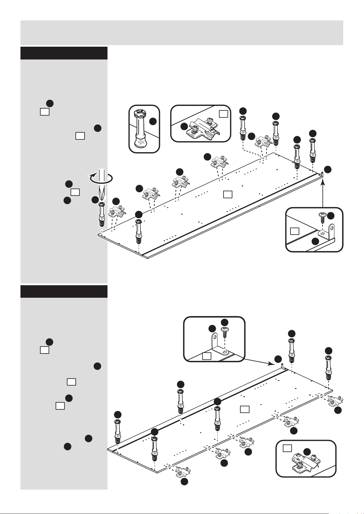
Step 3
Step 4
Assembly Instructions
L
J
E
Prepare the right side
Refer to step 1 and, if
required, fit 5 hinge
plates onto the right
side , as shown.
Screw 6 metal dowels
into the holes shown on
the right side .
Fit a bracket to the
right side , flush with
the top edge and back
edge, see diagram.
Secure the bracket
using screw .
2
B
2
J
J
2
E
B
B
B
B
B
B
L
L
L
L
J
2
2
2
L
L
J
E
Prepare the left side
Refer to step 1 and, if
required, fit 5 hinge
plates onto the left
side , as shown.
Screw 6 metal dowels
into the left side .
Note: Tighten the metal
dowels up fully against
the panels.
Fit a bracket
to the left side
using screw ,
flush with the top
edge and back
edge, see
diagram.
B
B
B
B
B
B
L
L
L
L
L
J
J
1
1
1
1
1
E
1
L
L
IMPORTANT
Only carry out this step if you are building a housing for a
fridge/freezer. If you are building a Larder Cupboard you have
already prepared this panel in Step 2.
B
B
IMPORTANT
Only carry out this step if you are building a Larder Cupboard.
If you are building a housing for a fridge/freezer go to Step 5.
Page 7

Assembly Instructions
6
Step 5
L
J
E
Prepare the right side
Refer to step 1 and, if
required, fit 5 hinge
plates onto the right
side , as shown.
Screw 6 metal dowels
into the holes shown on
the right side .
Fit a bracket to the
right side , flush with
the top edge and back
edge, see diagram.
Secure the bracket
using screw .
2
B
2
J
J
2
E
B
B
B
B
L
L
L
L
J
2
2
2
L
L
IMPORTANT
Only carry out this step if you are building a housing for a
fridge/freezer. If you are building a Larder Cupboard you have
already prepared this panel in Step 4.
A
A
A
A
A
A
C
C
C
C
A
A
A
A
A
A
C
C
C
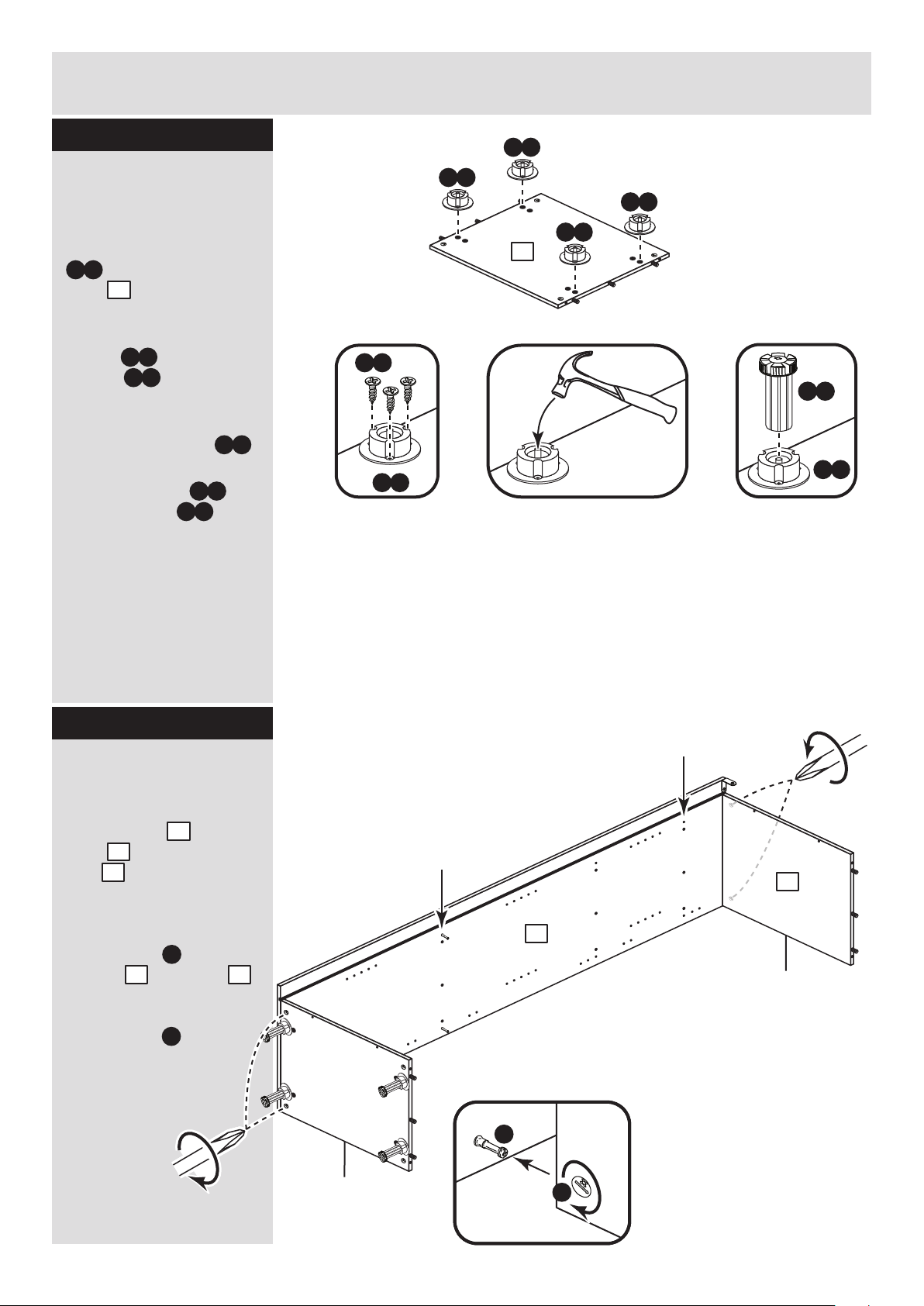
Prepare the base and
top
Insert 4 large locking
nuts into the base
and top as shown.
Note: Arrow on locking
nut must point towards
hole in edge of panel.
Tap 4 wooden dowels
into the base and top
. as shown.
Note: Wooden dowels
must not stick out from
the edge by more than
10mm or they may
damage other panels.
C
C
4
4
10mm
A
A
4
4
Step 6
4
4
C
B
B
Page 8
Assembly Instructions
7
Step 7
Finished
front edge
Finished
front edge
Join the base and top
to the right side
Push the top and
base onto the right
side .
Use a screwdriver to
tighten the 2 large
locking nuts fitted to
the top and base .
Note: Turn the large
locking nuts as far
as they will go - more
than 1/2 a turn.
4
4
44
2
C
C
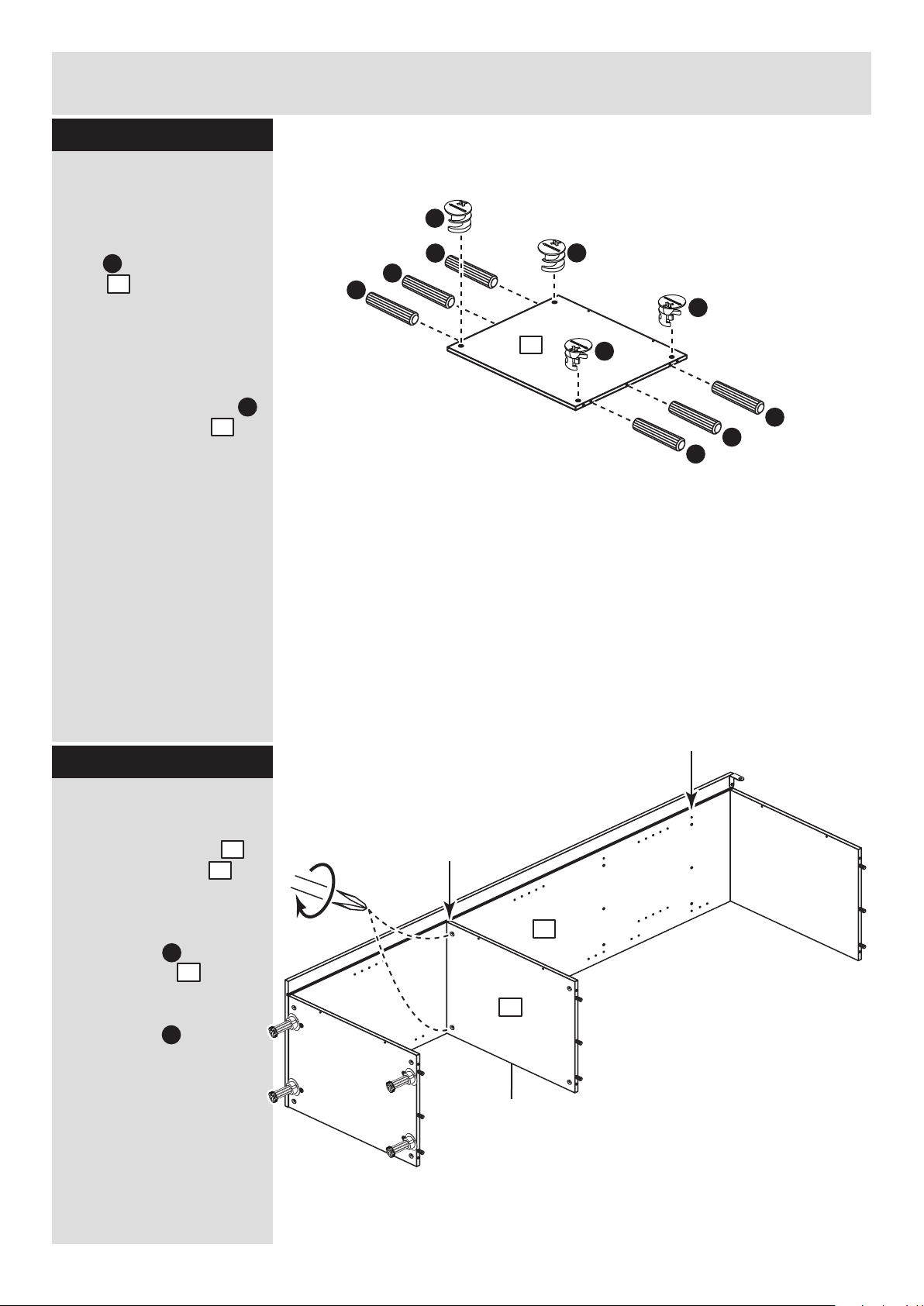
Step 8
B
C
4
4
2
I a
I b
b: c: d:
Fit the legs to the
base
a: Push the leg sockets
. into the holes in the
base as shown.
b: Secure each leg
socket with 3
screws .
c: Tap in the centre plug
on each leg socket .
d: Push the leg into
the leg socket .
I a
I a
I a
I e
I e
4
x 3
I a
I a
I b
I a
I a
I a
4
I a
NOTE: Hinge plates
are not shown as
you may have fitted
them to the left side.
If you are building a
housing for a
fridge/freezer these
2 metal dowels...
...will be here
Page 9
A
A
A
Assembly Instructions
8
Step 9
Step 10
Finished
front edge
Fit the fixed shelf
Push the fixed shelf
onto the right side .
Use a screwdriver to
tighten the 2 large
locking nuts fitted to
the fixed shelf .
Note: Turn the large
locking nuts as far as
they will go - more than
1/2 a turn.
6
2
C
C
2
6
6
A
A
A
C
C
C
C
Prepare the fixed
shelf
Insert 4 large locking
nuts into the fixed
shelf as shown.
Note: Arrow on locking
nut must point towards
hole in edge of panel.
Tap 6 wooden dowels
into the fixed shelf .
Note: Wooden dowels
must not stick out from
the edge by more than
10mm or they may
damage other panels.
C
6
A
6
6
If you are building a
housing for a
fridge/freezer this
fixed shelf...
...must be fitted here
Page 10

9
Assembly Instructions
Step 11
Fit the small back
Position the small back
. between the top
and fixed shelf , as
shown and secure it into
position using 4 screws
. .
2
6
P
P
IMPORTANT
Only carry out this step if you are building a housing for a
fridge/freezer. If you are building a Larder Cupboard please
ignore this step.
9
4
Step 12
Fit the left side
Push the left side
onto the assembly.
Use a screwdriver to
tighten the large locking
nuts fitted to the
base , top and
fixed shelf .
Note: Turn the
large locking
nuts as far
as they will go
- more than
1/2 a turn.
6
6
1
C
C
4 4
4
4
1
If you are building a
housing for a
fridge/freezer this
fixed shelf...
...will be fitted here
P
P
9
4
6
P
Page 11

Assembly Instructions
10
Step 13
Fit the back
a: Slide the back
along the grooves in the
side panels and .
3
1 2
3
1
2
Note: These 3
holes must be
nearest the bottom
edge of the panel.
IMPORTANT
Only carry out this step if you are building a Larder Cupboard.
If you are building a housing for a fridge/freezer please ignore
this step.
a:
b:
3
b: The bottom edge of
the back must be
flush with the bottom
edge of the base .
Secure the back to
the unit using 3 screws
. into the back edge of
the base , fixed shelf
. and top .
Stand the unit up for
the next stage.
3
3
4
4
6 4
6
4
F
4
F
F
F
F
F
F
F
F
F
Page 12
Assembly Instructions
11
Step 14
Warning: Take
care when
drilling the wall
that you do not
drill into any pipes, wires
etc. If in doubt, consult
an expert.
Secure the unit to the
wall
Using the brackets
fitted to the back edge of
the sides and
screw the unit to the
wall.
Fixings are not supplied
as they will need to suit
the wall type, and the
length of screw will
depend on the distance
of the back of the Unit to
the wall.
F
1 2
5mm
G
H
Joining units together
Fittings have been
supplied so you are able
to join units together.
Make sure that your first
unit is level.
Push the other unit up
against first unit and
ensure both units are
level.
Check that the ends are
flush and in line, then
clamp them together.
Using a 5mm drill bit,
drill 2 holes (approximate
positions shown circled)
in the side panel into the
adjoining side panel of
the other unit.
Push the connecting
sleeves into the holes
and then screw the
connecting bolts in
from the other side.
G
H
Step 15
2
1
Page 13
Assembly Instructions
12
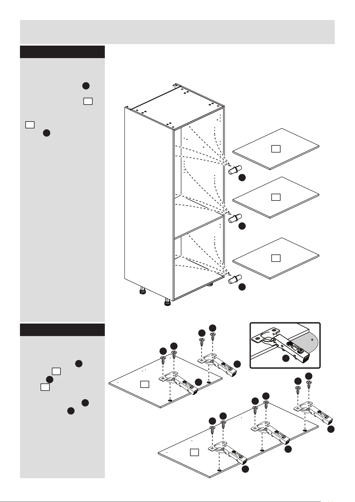
Step 16
Prepare the doors
Push fit 2 hinges into
the door and 3
hinges into the larder
door .
Secure each hinge
with 2 screws .
Note: Before securing
with the screws, make
sure that the hinges are
positioned at 90 degrees
with the front edge of the
door.
M
D
M
7
8
7
8
90
M
M
D
D
M
D
D
M
D
D
M
D
D
M
D
D
M
Fit the loose shelves
Insert 4 shelf studs at
the required height for
each of the shelves .
Lower the loose shelves
. down onto the shelf
studs .
K
K
5
5
K
x 4
K
x 4
K
x 4
5
5
5
IMPORTANT
Only carry out this step if you are building a Larder Cupboard.
If you are building a housing for a fridge/freezer please ignore
this step.
Step 17
Page 14
Assembly Instructions
13
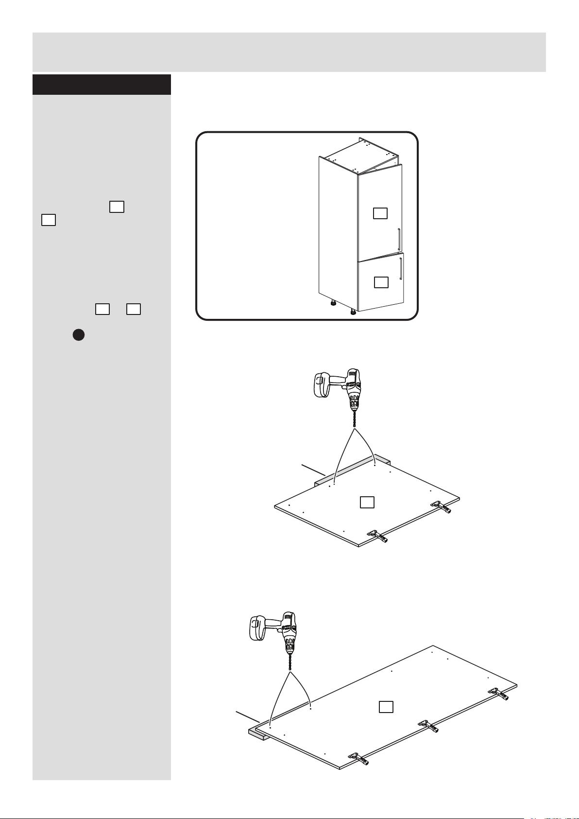
Step 18
Drill the handle holes
in the door
Important: Please follow
these instructions
carefully.
Lay the doors and
. down onto a smooth
surface.
Important: Carefully
choose which holes you
need to drill.
This will depend on
which side or
you fitted the hinge
plates .
Check that the holes and
hinges are in the same
place as the diagrams.
Note: We recommend
the use of a small piece
of waste wood, placed
behind the hole while
drilling, to reduce the
possibility of any
breakout.
Using the pilot hole in
the rear face of the door,
drill through the holes
indicated opposite, using
a 2.5mm diameter drill.
Turn the door over and
open out the 2.5mm
holes that you have just
drilled by drilling back
through them with a
5mm drill.
Note: Drill bits are not
provided.
7
8
2
L
1
7
8
Important
ONLY drill the
2 holes in each
door shown
here if you
have fitted the
hinges to the
LEFT side.
If you have
fitted the
hinges on the
RIGHT side,
go to the
next step.
Small piece of
waste wood
DO NOT drill
any other holes
ONLY drill
these 2 holes
DO NOT drill
any other holes
ONLY drill
these 2 holes
Small piece of
waste wood
7
8
PLEASE FOLLOW THESE INSTRUCTIONS CAREFULLY
TO CHOOSE WHICH 2 HOLES YOU WILL NEED TO DRILL
Page 15

Assembly Instructions
14
Step 19
Small piece of
waste wood
Drill the handle holes
in the door
Important: Please follow
these instructions
carefully.
Lay the doors and
. down onto a smooth
surface.
Important: Carefully
choose which holes you
need to drill.
This will depend on
which side or
you fitted the hinge
plates .
Check that the holes and
hinges are in the same
place as the diagrams.
Note: We recommend
the use of a small piece
of waste wood, placed
behind the hole while
drilling, to reduce the
possibility of any
breakout.
Using the pilot hole in
the rear face of the door,
drill through the holes
indicated opposite, using
a 2.5mm diameter drill.
Turn the door over and
open out the 2.5mm
holes that you have just
drilled by drilling back
through them with a
5mm drill.
Note: Drill bits are not
provided.
In the next step, fit the
handles using the holes
you have drilled here.
7
8
2
L
1
8
7
Important
ONLY drill the
2 holes in each
door shown
here if you
have fitted the
hinges to the
RIGHT side.
DO NOT drill
any other holes
ONLY drill
these 2 holes
Small piece of
waste wood
DO NOT drill
any other holes
ONLY drill
these 2 holes
7
8
PLEASE FOLLOW THESE INSTRUCTIONS CAREFULLY
TO CHOOSE WHICH 2 HOLES YOU WILL NEED TO DRILL
If you have
fitted the
hinges on the
LEFT side,
go to the
previous step.
Page 16

Assembly Instructions
15
Step 20
O a
a:
b:
c:
This shows the doors being fitted to
hinge plates on the right side.
You may have fitted them to the left side.
Push and
click
Push
d:
Fit doors and handles
2 people are needed
here
Note: The easiest way to
attach each door and
. is to fit the top hinge
first, then align and fit the
other hinge(s).
a: Push the hooks on
the hinge arm
underneath the front of
the hinge plate .
b: Press the front of the
hinge arm against the
hinge plate until it
clicks into place.
c: If you need to
seperate the hinge arm
. from the hinge plate,
. press the button at
the end of the hinge arm
and lift it off of the hinge
plate.
d: Attach a handle
to each door and
using the 2 screws
packed with it.
L
M
M
L
L
M
L
M
L
L
M
7
8
M
L
M
O a
O b
7 8
7
8
O a
O b
O b
Page 17

Assembly Instructions
16
Step 21
Adjust the doors if
needed
a: Height adjustment.
Loosen screws A on
hinge plates and move
door up or down as
required.
Retighten screw A.
b: Forward and Back
adjustment.
Loosen screw B on hinge
arm and move door in or
out as required.
Retighten screw B.
c: Sideways
adjustment.
To move door ‘out’
loosen screw C.
To move door ‘in’ tighten
screw C
a:
b:
c:
A
A
C
B
Page 18
Assembly Instructions
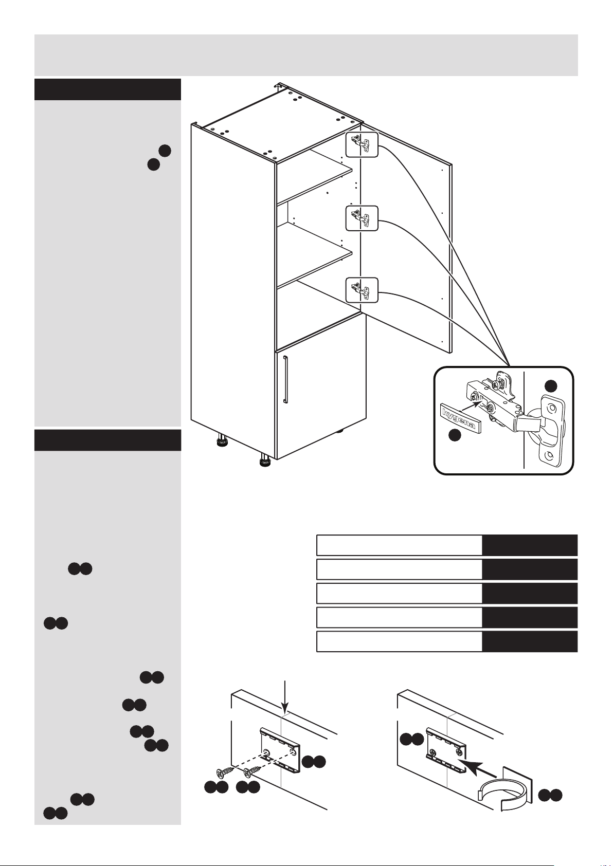
17
Step 22
Fit the hinge covers
Push the hinge covers
onto the hinge arms .
N
M
h
ygen
a
N
M
Step 23
Pencil mark
Plinth
I c
I c
I d
Plinth
I e I e
Fit the plinth
After cutting the plinth to
the required length, offer
the plinth up to the unit
and using a pencil, mark
the position of the unit’s
legs on the back of
the plinth.
Position the leg bracket
. so it is in the centre
of the pencil mark and
half way up the plinth.
Fix the leg bracket
to the back of the plinth
using 2 screws .
Slide the leg clip
into the leg bracket
Offer the plinth up to the
unit and push the leg
clips onto the legs
. .
I b
I b
I c
I c
I c
I d
I d
.
I e
608/2345
608/2369
205/5668
198/9917
608/2352
Black Plinth Pack
Cream Plinth Pack
Oak Plinth Pack
White HN Plinth Pack
White Gloss Plinth Pack
Page 19

Assembly Instructions
18
If you need help or have damaged or missing parts, call the Customer Helpline: 08456 400800
and quote the reference numbers on the component pages.
Argos Ltd, 489-499 Avebury Boulevard, Central Milton Keynes, MK9 2NW
Step 24
Fit other products to
the unit
To fit other products to
this unit e.g. worktops
etc., please follow the
instructions packed with
them.
We recommend that you
consult a qualified joiner
or kitchen fitter.
Assembly is complete
Warning: The
unit is heavy.
Lift with care.
Please dispose of any unused panels and fittings carefully and responsibly.
They should not be discarded with household waste.
Take them to your local authority waste disposal centre.
Page 20

ALR2657
 Loading...