

Hy-Gain VB-216SAT Instruction Manual

Model No. VB-216SAT
y
b
2-Meter OSCAR Satellite Anten na
Model 216 SAT
INSTRUCTION MANUAL
GENERAL DESCRIPTIO N
The Hy-Gain Model 216 SAT is a high-performance "OSCAR" (Orbiting Satellite Carrying
Amateur Radio) satellite antenna for the 145.8 -
146.0 MHz frequency band. It features
polarization switching circuity for manual selection of either Right Hand Circular Polarization
(RHCP) or Left Hand Circular Polarization
(LHCP). This flexible design is suitable for
worldwide applications with any of the amateur
satellites having either an uplink or downlink in
the 145.8 - 146.0 MHz frequency range, such as
AO-10, FO-12, AO-13, DO-17, AO-16, LO-19,
U O-22, KO-23, RS-10, RS-11, RS-12, RS-13,
etc. These include modes A, B, J, JA, JD, JL,
KA, KT, and T.
It is also usable over the entire 2-meter band,
144-148 MHz; and could be used with future
satellites placed near 144.5 MHz, or with terrestrial modes such as repeaters and SSB/CW
DX. The vertical and horizontal sets of elements
may he fed with separate feedlines for total
flexibilit
.
The 216 SAT Antenna features 16 elements
(total) on a 2.1 wavelength boom. Each set of 8
elements is designed to give 10.7 dBd gain based
on a quasi-logarithmic tapering of element
spacings. This design also gives a very clean
pattern, with very small sidelobes. The 216 SAT
also features high efficiency "T" matched driven
elements for easy assembly and high gain. True
R F, 50 ohm switching relays are rated at 200
watts PEP and contribute to improved VSWR.
Feedpoints are encapsulated for long life in all
types of climates. Most hardware is stainless
steel including the element retaining rings
(pushnuts). All insulators are UV protected. The
coaxial assembly is made from high-quality
Polytetrafluoethylene (PTFE) dielectric and
Fluorinated Ethylene Propylene (FEP) jacketed
coaxial cable.
The 216 SAT "OSCAR" beam can be used with
the Hy-Gain 70-30 SAT 70 cm OSCAR Beam
and the 217S, fiberglass, 5 foot boom, or it can
be used with other commercial or "homebrew"
"OSCAR" antennas. The 216 SAT antennas may
e stacked for more gain.
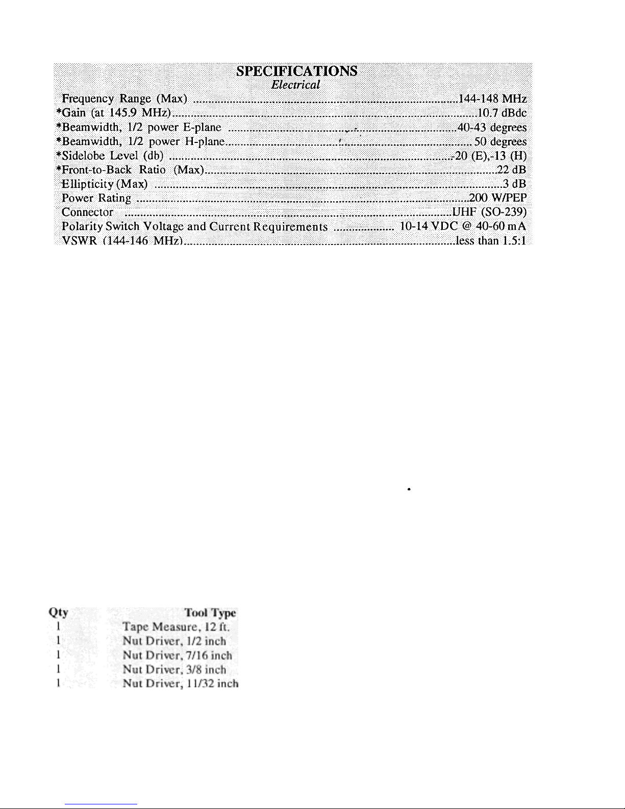
Boom Length................................................................................. ...........168.75 in. (429 cm)
Maximum Boom O.D. .......................................................................1.25 in. (32 mm)
Turning Radius (Max) .................................:..............................................8.ft. (2.44 m)
Total Number of Elements ...............................................................…………............16
Longest Element .....................................................................................39.5 in. (100 c m)
Wind Survival........................................... .......................................80 mph (128.7 km/h)
Mast/Boom Diameter Accepted ............................. 1.250-1.625 in. (32 mm - 41 mm)
Wind Area....................................................................................... .....1.1 sq. ft. (.102 sq. m)
Net Weight............................................................ ............................7 lbs.3 o z. (3.26 kg)
Stacking Distance (min).............................................'....82 in. (2.08
SPECIFICATIONS
Mechanical
m) (1.0 wavelength)
PREPARATION FOR ASSEMBLY
p
FOR OUR OVERSEAS CUSTOMERS: If you
use the Metric System, see the American-toMetric Conversion Table in the rear of this
manual. Most illustrations in this manual will
provide both American and Metric dimensions.
One nut driver should have a hollow handle.
This can be used for pushing on the pushnuts.
Standard wrenches or adjustable wrenches
may also be used in place of the nut drivers.
When unpacking your antenna, check inside of
all tubing for small parts and elements. To con-
serve space, these smaller articles are
Choose a moderate-sized clear area to assemble
the 216 SAT OSCAR Beam. The area must be at
least 5' x 5' (1.5 x 1.5 m) for each boom section.
A bench vise is recommended to hold the booms
while the elements are being installed. An
alternate method is to drive a 5' (1.5 m) length
of mast material into the ground and attach the
entire boom and boom-to-mast bracket to this
mast temporarily during assembly.
sometimes put inside larger pieces. Check all
parts against the parts list in the rear of this
manual to ensure no
arts are missing.
Make all measurements to the given dimen-
sions, plus or minus, no more than 1/16 inch!
The assembly of this antenna will be easier if
you read this manual completely through at
least twice and follow the recommended direc-
tions. Allow at least 4 hours for assembly.
If you assemble this antenna over a grassy area,
precautions should be taken so that hardware is
not accidentally lost during assembly. A concrete driveway is an excellent area for
assembly.
Tools: The following tools are required for easy' as-
seinbl y
of the 216 SAT OSCAR Beam:
BOOM ASSEMBLY
Select the boom sections, boom-to-mast brack-
et parts and hardware as shown in Figure 1.
Identify the boom sections by their length and
diameter, and identify the mating ends from the
dimensions shown in Figure 1. Assemble the
boom sections and boom-insert with the
hardware as shown, and tighten securely.
NOTE: Another complete set of element
mounting holes exists in the vertical plane and
is not shown in Figure 1. This set has element
mounting holes which are offset approximately
20 1/4 inches towards the front of the boom
assembly. This is 1/4-wave (90 degrees) at 146
MHz.
Gain and Patterns verified by Yagi Opti m izer 4.0 (C) and NEC, and by measurements of f ull size. ante nnas on Ily-Gain's antenna range. (C)
Copyright by Brian Beezley
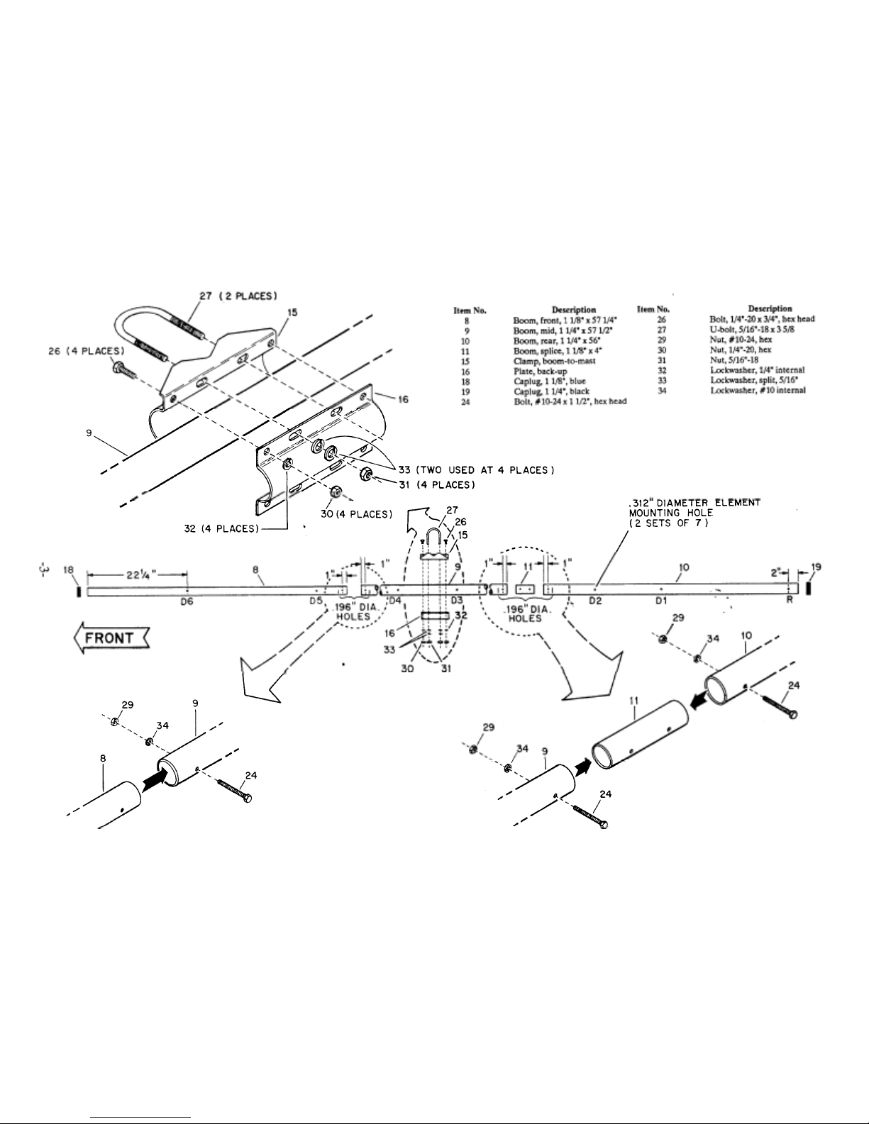
Figure 1 Boom
Assembly
After assembly, the boom-to-mast bracket may
(
p
m
be rotated on the boom so that after mounting,
the elements are in an "X" configuration.
Securely tighten the 1/4"-20 x 3/4" hardware.
When the bracket is in the desired position.
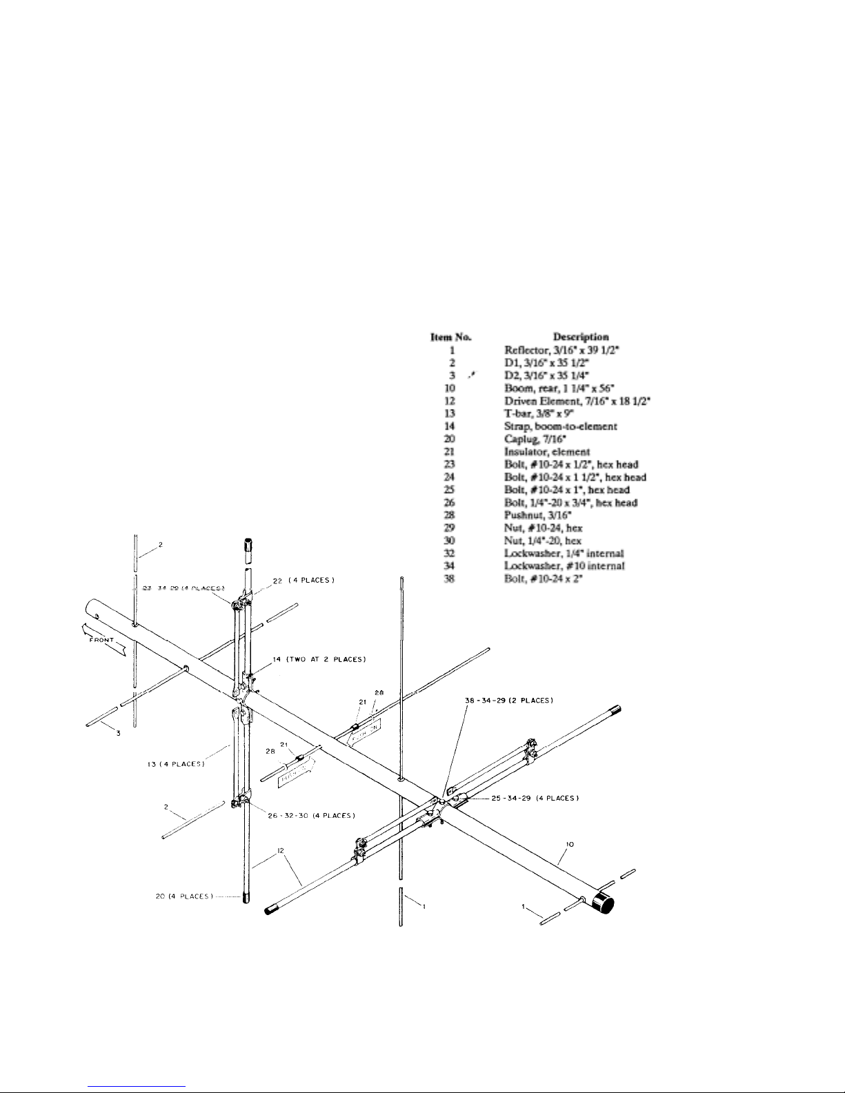
-Select the four (4) driven element halves,
7/16" 'x 18-1/2" (Item 12), T-Bar (Item 13),
boom-toelement strap (Item 14), and driven
element clamps (item 22) and associated
hardware as shown in Figure 2.
Assemble the two driven elements to the boom
as shown in Figure 2. The distance from the
boom to the edge of the driven element clamps
(Item 22) should be 8 5/16" (21 cm). Securely
tighten all hardware. When the coax/switch
assemble is installed later, you will decide on
either LHCP or RHCP from the unswitched
olarization.
ASSEMBLY OF OTHER ELEMENTS
Select the two reflector elements, 3/16" x 39
1/2" (Item 1), marked with 2 black bands near
one end of each. Also select four insulators
Item 21) and four - 3/16" pushnuts (Item 28).
Install the reflector elements on the rear boom
as shown in Figure 2. Push one of the element
insulators (Item 21) onto each reflector, so that
its shoulder is 19 1/8" from the nearest end. In-
sert the long end of each reflector into the
reflector mounting holes, as shown in Figure 2.
Figure 2 Assembly of Driven
Elements, Reflectors and
Directors to Boo
 Loading...