

Hy-Gain UB-7030SAT Instruction Manual

S
ill
39759 USA
UB-7030SAT
yp
d
b
308 Industrial Park Road
tarkv
Ph: (662) 323-9538 FAX: (662) 323-
e, MS
INSTRUCTION MANUAL
GENERAL DESCRIPT ION
The Hy-Gain Model 70-30 SAT is a highperformance "OSCAR" (Orbiting Satellite
Carrying Amateur Radio) satellite antenna for the
432-438 MHz frequency band. It features
polarization switching circuitry for manual
selection of either Right Hand Circular
Polarization (RHCP) or Left Hand Circular
Polarization (LHCP). This flexible design is
suitable for worldwide applications with any of
the amateur satellites having either an uplink or
downlink in the 432-438 MHz frequency range
such as AO-10, FO-12, AO-13, UO-14, AO16,
LO-19, AO-21, UO-22, KO-23, etc. These include
modes B, J, JA, JD, JL, L and S.
The 70-30 SAT antenna features 30 elements (total) on a 4.2 wavelength boom. Each set of 15
elements is designed to give 14.0 dBd gain based
upon the NBS Tech Note 688. The 70-30 SAT
also features high efficiency "Delta" matched
driven elements for easy assembly and rugged
durability. True RF 50 ohm switching relays are
rated at 200 watts and contribute to improved
VSWR. Feed points are encapsulated for lo ng life
in all t
es of climates.
UHF 432 - 438 MHz
Satellite Antenna
Most hardware is stainless steel including the element pushnuts. All insulators are UV protected.
The coaxial assemblies are made from high-quality Polytetrafluoroethylene (PTFE) dielectric and
Fluorinated Propylene (FEP) jacketed coax cable.
The 70-30 SAT "OSCAR" antenna can be use
with the Hy-Gain 216 SAT 2-meter "OSCAR"
antenna and the 217S fiberglass 5 foot boom, or it
can be used with other commercial or homebrew
"OSCAR" antennas. The 70-30 SAT antennas may
e stacked for more gain.
PREPARATION FOR ASSEMBLY
FOR OUR OVERSEAS CUSTOMERS: If you
use the Metric System, see the Americ an-to- Metric Conversion Table in the rear of this manual.
Most illustrations in this manual will provide both
Choose a moderate-sized clear area to assemble
the 70-30 SAT Oscar Beam. The area must be at
least 24" x 63" for each boom section.
Boom Length ...................................................................................................134 in. (340.4 cm)
Maximum Boom O.D. ....................................................................................1.125 in (28.6 mm)
Turning Radius (Max).......................................................................................71.25 in (181 cm)
Total Number of Elements ......................................................................................................30
Longest Element .....................................................................................................13 in. (33 cm)
Wind Survival ..............................................................................................80 mph (128.7 km/h)
Mast/Boom Diameter Accepted ..............................................1.250 - 1.625 in (32 mm - 41 mm)
Wind Area ................................................................:............................. 0.75 sq. ft. (.0697 sq. m)
Net Weight ................................................................................................... 4 lbs 14 oz (2.21 kg)
Stacking Distance (Min) ......................................................46 inches (1.17m) (1.7 wavelengths)
SPECIFICATIONS
Mechanical
SPECIFICATIONS
(
Electrical
Frequency Range...................................................................….................................432-438 MHz
Gain ...............................................................................…..............................................14.0 dBdc
Beamwidth...................................................................………............................................28-30 degrees
Front-to-Back Ratio.....................................................…..................................................... 25 dB
Ellipticity ...................................................................................................................... 3 dB Max.
Power Rating .............................................................................................................. 200 W/PEP
Connector .......................................................................................................................... Type N
Polarity Switch Voltage and Current Requirements …………………… 9-15 VDC @ 30-60 mA
VSWR (435-437 MHz) .............................................. Less than 1.5 when using fiberglass boom
A bench-vise with jaws no wider than 6 inches is
recommended to hold the booms while the elements are being installed. An alternate method is
to drive a 5' (1.5 m) length of mast material into
the ground and attach the entire boom and boomto-mast bracket to this mast temporarily during
assembly. If you assemble this antenna over a
grassy area, protection should be taken so that
hardware is not accidentally lost during assembl y.
A concrete driveway is an excellent area for assembly.
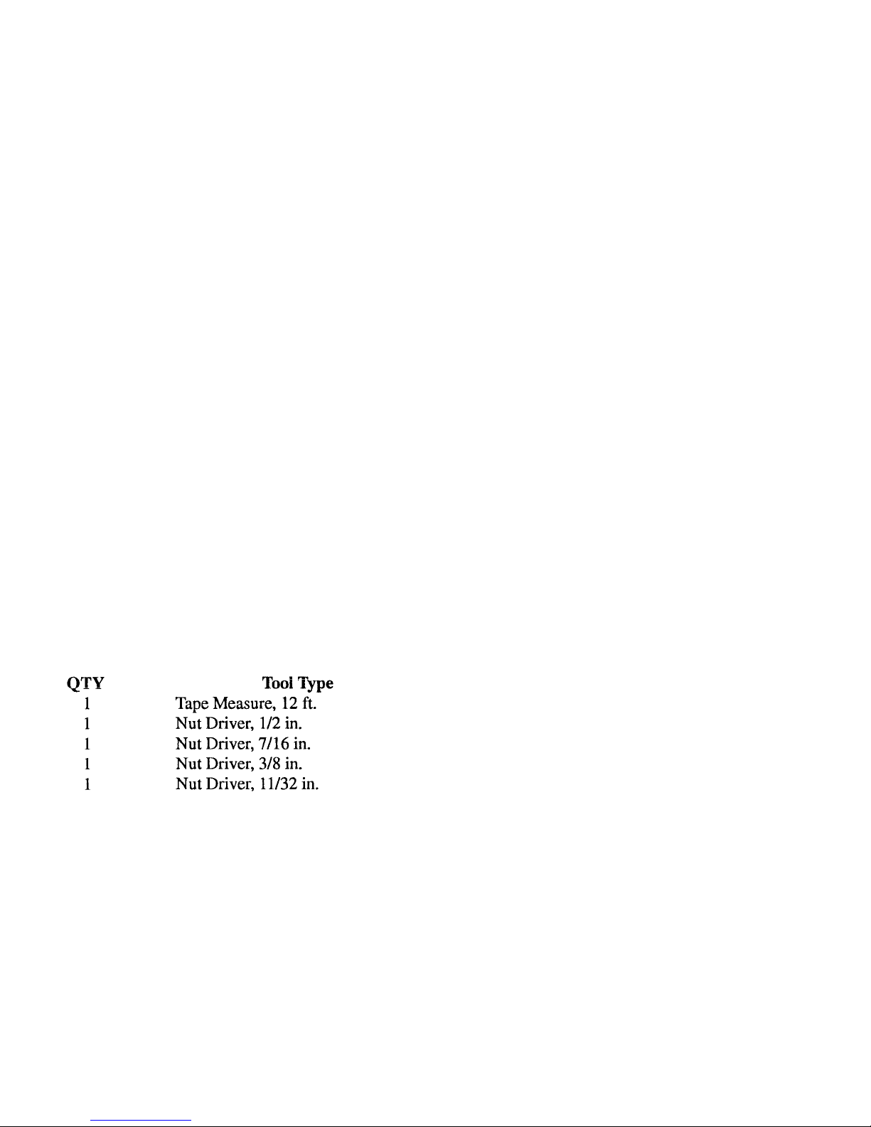
Tools: The following tools are required for
easy assembly of the 70-30 SAT OSCAR
Beam:
Make all measurements to the given dimensions,
plus or minus, no more than 1/16 inch! The assembly of this antenna will be easier if you read
this manual completely through at least twice and
follow the recommended directions. Allow at least
4 hours for assembly.
ASSEMBLY OF THE BOOM-TO
MAST BRACKETS AND BOOM
Select the boom-to-bracket parts, boom sections
and mast bracket parts as shown in Figure 1. Lineup the holes in the 3 boom sections as shown. The
front and rear boom sections should meet at the
center of the boom insert (Item 13).
NOTE: Another complete set of element mounting holes exist in the vertical plane and is not
shown in Figure 1. This set has identical spacings
between holes but is offset approximately 6 3/4
inches towards the rear of the boom assembly.
This is 1/4 wave
90 degrees) at 435 MHz.
A 3/8 inch by 6 inch tube (Item 35) is supplied to
help install the insulators and pushnuts. Standard
wrenches or adjustable wrenches may also be
used in place of nut drivers.
When unpacking your antenna, check inside of all
tubing for small parts and elements. To conserve
space, these smaller articles are sometimes put
inside larger pieces. Check all parts against the
parts list in the rear of this manual to ensure no
parts are missing.
After assembly, the boom-too-mast bracket may
be rotated on the boom so that after mounting, the
elements are in an "X" configuration. Securely
tighten the 1/4" - 20 x 3/4" hardware when the
bracket is in the desired position. Securely tighten
the #10 - 24 x 1 1/2" bolt which holds the coax
support boom to the rear boom.
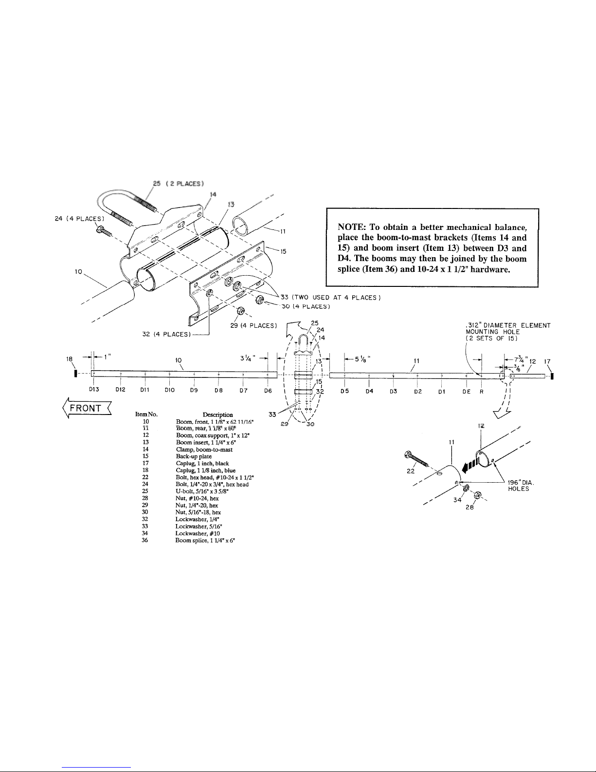
Figure 1
Assembly of Boom and Boom-To-Mast Bracket
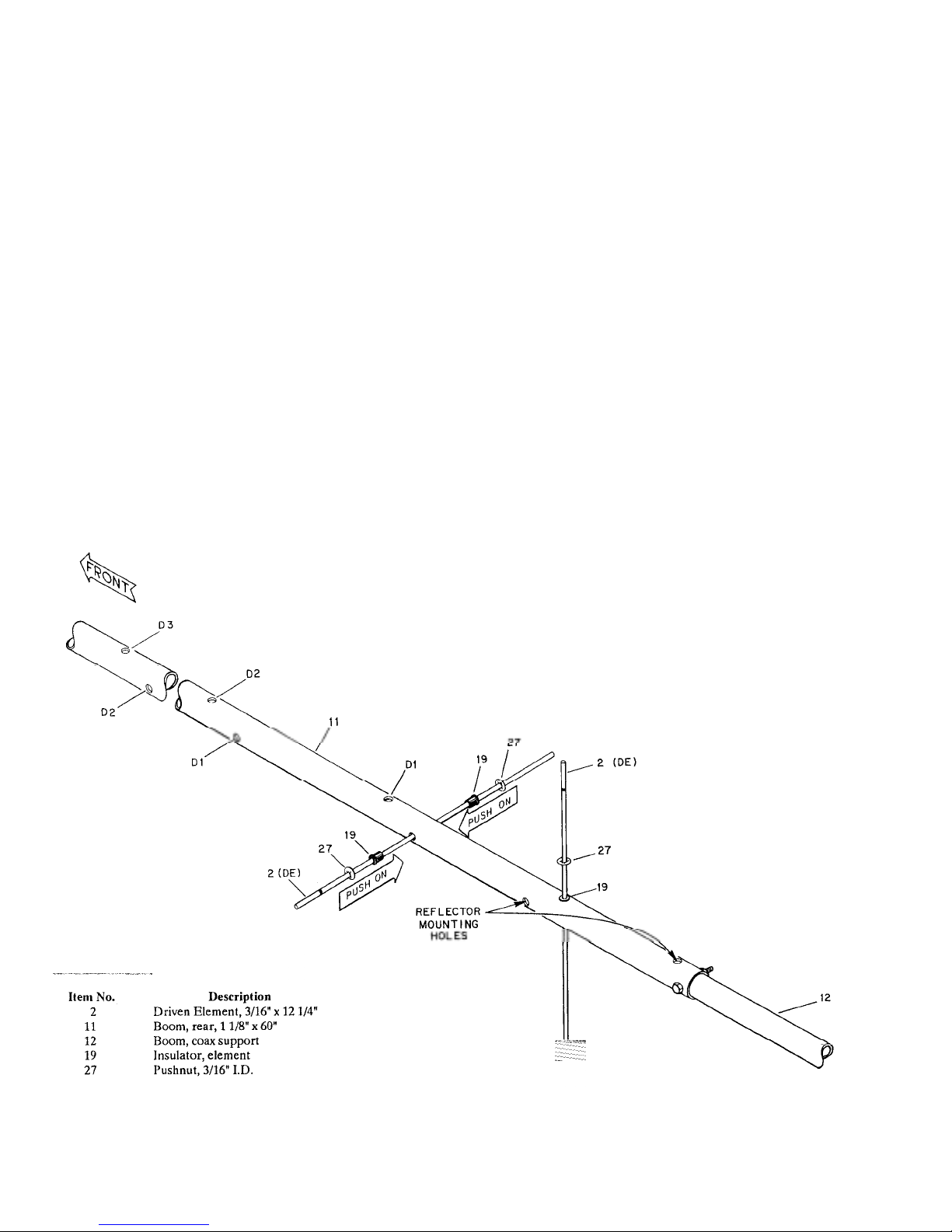
ASSEMBLY OF DRIVEN ELEMENTS
p
Select the two (2) driven elements, 3/16" x 12
1/4", marked with a single black color band
need one end of each. Also select the insulators
and pushnuts as shown in Figure 2.
Push one of the element insulators (Item 19)
onto each Driven Element (DE) so that its
shoulder is 5 9/16" from the nearest end (as
shown in Figure 3). I nsert t he long end of eac h
DE into the driven element moun ting holes on
the rear boom section, as shown in Figure 2.
Slide another element ins ulator (Item 19) over
the other end of the DE's, and push it onto each
element until it seats into the mounting hole.
Recheck the exposed length of the DE's and
reposition if necessary.
Carefully slip the 3/16 inch pushnuts (ite m 27)
over each end of the t wo (2) driven elements,
and push them along each element until they
are snug against each element insulator. Check
the exposed length of each DE during this
process, to ensure the correct dimensions.
NOTE: You may wish to use the sho rt length
of tubing to help push the element insulators
and pushnuts. If you accidentally slide a
pushnut on too far, then you should cut it off
the element and tr y again wit h one of the s pare
Select the DE T-Bars ( Item 20), and 3/16 inch
tubing clamps (Item 21), and associated
hardware. Assemble these parts to the driven
elements as shown in Figures 3 and 4. When
the coax assembly is installed later you will
decide on either LHCP or RHCP for the unswitched
olarization. See Figures 6 and 7.
Driven Element Location and Assembly
Figure 2
 Loading...