

Hy-Gain TH3-MK3 Thunderbird Instruction Manual
o
rrut
I
ft
-i
General
$peclfications
t
I
i
,n,electronics
DIVISION
OF TELEX
COMMUNICATIONS, INC.
,wSrRUCTtOrv
MANUAL
The
DescrlPllon
Hy-Gain
10, 15
on
Hy-Q
traps.
with
a heavy
Inputimpedance.
Gain.
Front-to-backratio
Maximum
VSWR
Lightning
B::il:l#$";
Longest
Maxrmum wino
Net
weignt.
Accepts
Wind
surface
Wind
load
TH3-Mk3
and
20 meters. Multi-barlding is
The
antenna is desig$ed to fit
duty TV
power
(at
resonance)...
protection
input
::::::::::::::g::::::::::::::::::::
element
survivat.......&....
mast.
. .i.Fr, . .
area
mph
at B0
S6OlrNortheast
Telephone:
EUFIOPE: 22,
93200 Saint-Denis
Tdldohone:
ORDER
TH3.
3-Element, Ham Antenna
.Et
4i
MK3
Highway
467-5321 telex: Hygain
t4O?,
rue
de la Ldgiond'Honneur
-
820.98.46
France
NO.
THUNDERBIRD
6 . Lincoln,
Telcodi
telex:
Nebraska
630013
388
68505 U.S.A.
48-4324
Lcn a
PN 801235
s
is a three-d.iement
rotator.
F
:
t
"r
$
:.....$.........
..::::::.::f::::::::::::::::::::::::::::::::::;;it,i?"l*tr
.....ft.:
. .i....
... ....t
....
t:
f
f;n
l;
tri-band beam antenna
accomplished through
(41
a 1s/e"
Ebctricat
Mechanical
mm) O.D. mast
designed for operation
the use of Hy-Gain's
and can
be
....25d8
.....
DC
all
rotated
1 kw AM
ground
'11,11?3,Til1
:::::::::::
.....:.9....
.......}]
...#.
..r...
.11A" lo 2V2"
....2i
.... 100 mph
(32
O.D.
...5.10 sq.
(823.7
ft.
(160.93
mm
ft.
kmph)
-
64 mm)
(0.474m2)
cm)
(.r
FOR
measurement Please
hardware and
Preparation
ol Assembly
OVERSEAS
OUR
CUSTOMERS:
the last
see
components supplied with
The
antenna site should
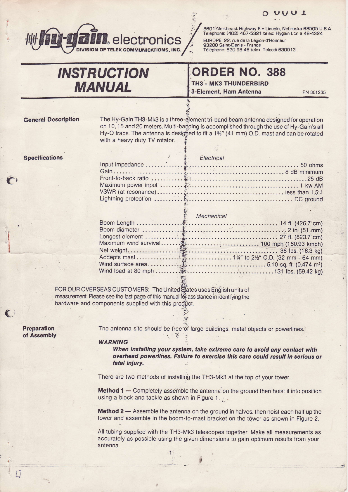
wARNtNc
When Installtng
overhead
fatal
There
are
Method
using a block and tackle
Method
lower and
All tubing
accurately
antenna.
page
tnlury.
two methods
1 - Completely
-
Assemble
2
assemble
supplied
as
The
of this manualSassistance
your
powerllnes.
the
in the
with
the TH3-Mk3
possible
using
*
{-r\i
UnitedSates
prodbct
this
.
Oe treeiOt large
'
i1
system,
Fatture to
of installing
assemble
as shown
antenna
boom-to-mast bracket
lhe
uses En0lish
:i'..
;:i
buildings, metal
'',-'
take
extreme cara to
exerclse thls
the TH3-Mk3
the
antenna
in
Figure 1.
on
given
ground
the
telescopes
dimensions
units of
in identifying
on the
-.
the
care could
at the top
ground
_
in
halves,
on the tower
together. Make
gain
to
objects
avold any contact wlth
of
then hoist
optimum results from
powertines.
or
ln
result
your
tower.
hoist it into
then
as
shown
all measurements as
serlous or
half
each
in Figure
position
up the
2.
your
n
When
Installlng
extreme
overhead
thls carc
lnlury.
WARNING
your
to avold any contact
care
powerllnes.
could
Falture
resull ln
system,
exerclse
to
serlous
or
take
wlth
latal
A0-0388-C-OO2
.
.,"
,t,,1..'"""*-
.,.,
Assembly
Boom
the
ol
Figure
1
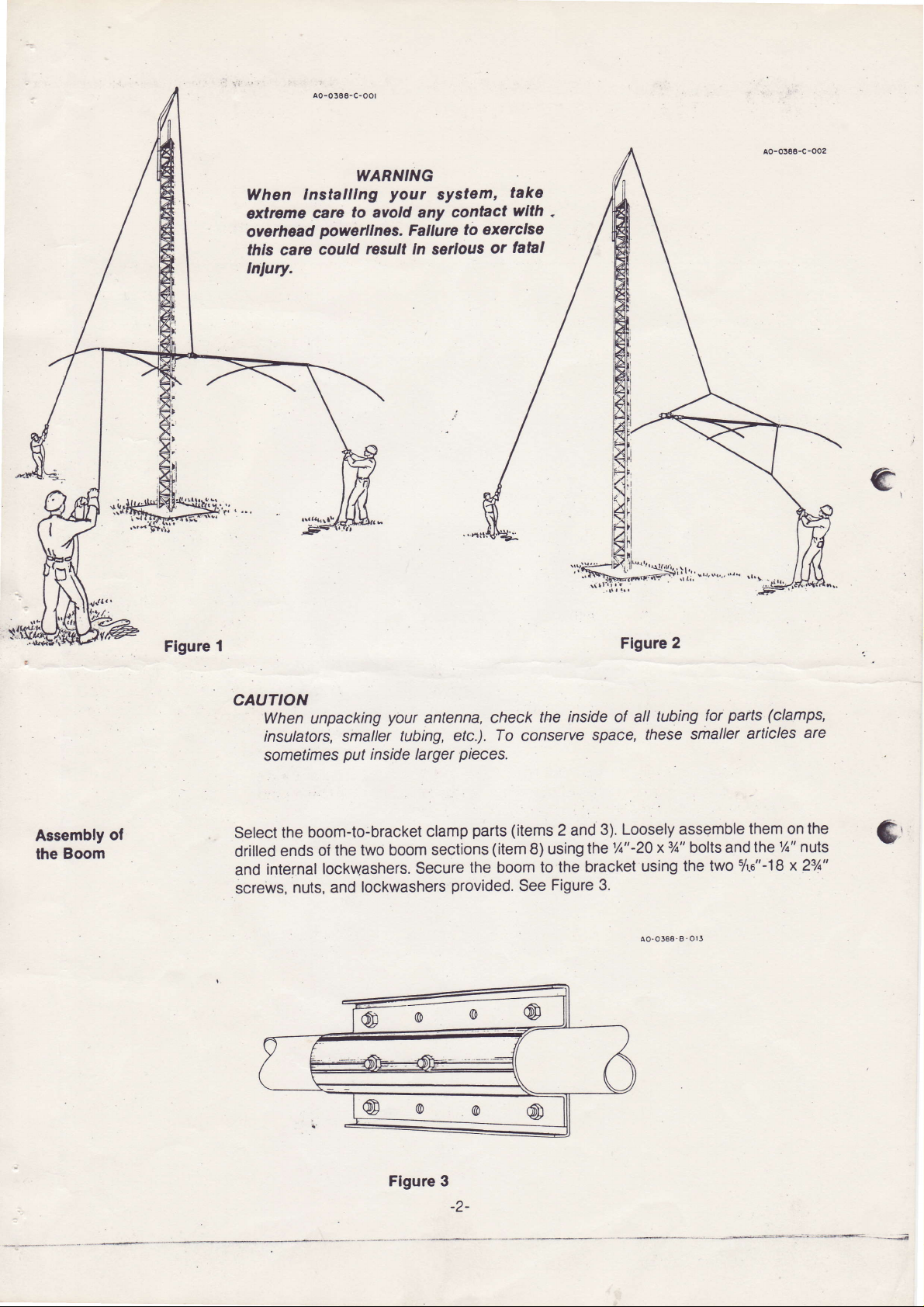
CAUTION
When unpacking
insulators, smalter
sometimes
Select
drilled
internaf
and
screws,
put
inside larger
boom-to:bracket
the
two boom
oi the
ends
lockwashers.
lockwashers
and
nuts,
:
dDoule,
@
your
antenna,
tubing,
Secure
(D
etc.).
pieces.
parts (items
clamp
sections
the boom
provided.
@
check
To
conserve
(item
8) using
See
@
inside of all
the
space,
3). Loosely
2 and
the1A"'20
the bracket
to
Figure 3.
('
\g
Flgure
using
ao-0388-8-OlJ
,<
2
tubing
these
assemble
3/a"
x
bolts and
the two
parts
for
smaller
sh.a"-18x23/0"
(clamps,
articles
are
them on the
7a" nuts
the
$r
Flgure 3
-2-

the
Select
mast
and the
cast aluminum
bracket
s/ro"
nuts
and 5. Do not
mount
the
antenna
boom-to-mast bracket
with the holes
and split
tighten
to the
lockwashers
the
screws at this time.
mast.
in
the
boom-to-bracket
to
(item
clamp.
join
the bracket and
The
bracket
1). Align the holes in the boom-toUs:e the
the clamp.
must
be
s/
'a"-18 x 5"
loose
to enable
See
screws
Figures
you
4
to
NOTE: The
boom-to-mast brackets have a hole
to the mast with the
an11
is
not
weather
hole
/32"
possible,
be drilled at the desired mast
the
conditions.
tr-18 r 5' 8oLT. LocKwasHEn ail
(tr9tcot
Figure 4
5
/ rc"-18
clamp
4
Dtocaa )
BOOM.TO.MAST
BRACKET
thrcugh
x31/2" bolt. lt is recommended
position,
clamp
will
hold
tur
position
its
on the mast in all
their
centers to allow securing
that the mast
removed and
be
then reinstallthe mast.
but the
t^-@o.c-o2t
most severe
AO-0388-B-014
lf
this
-a-6
$.-rBr!h'!olt,
LOCIWASXER od XUT
(O9lloml
d 16.
tro&cta,
3Yt' 3o!T,
1.-[r
locxwlsaEn.nd NUT
(
ploc..
Irplcol 2
t
Alutttlx
casT
ARACKETS
-
?6-18r2t'
-@-o,li
CASTING
IAST
Figure
-TO.8OOT
(Suppli.d
5
rcLr,
LocKwAsrER o.d
--H
CLAilP
!r
curroil..l
BOOX-TO'SRACXET CLAIP
L-
k-zo'1,'eorr.
NUT
LocKw sHER od rur
(
4
ltplccl
,locat
)
-3-
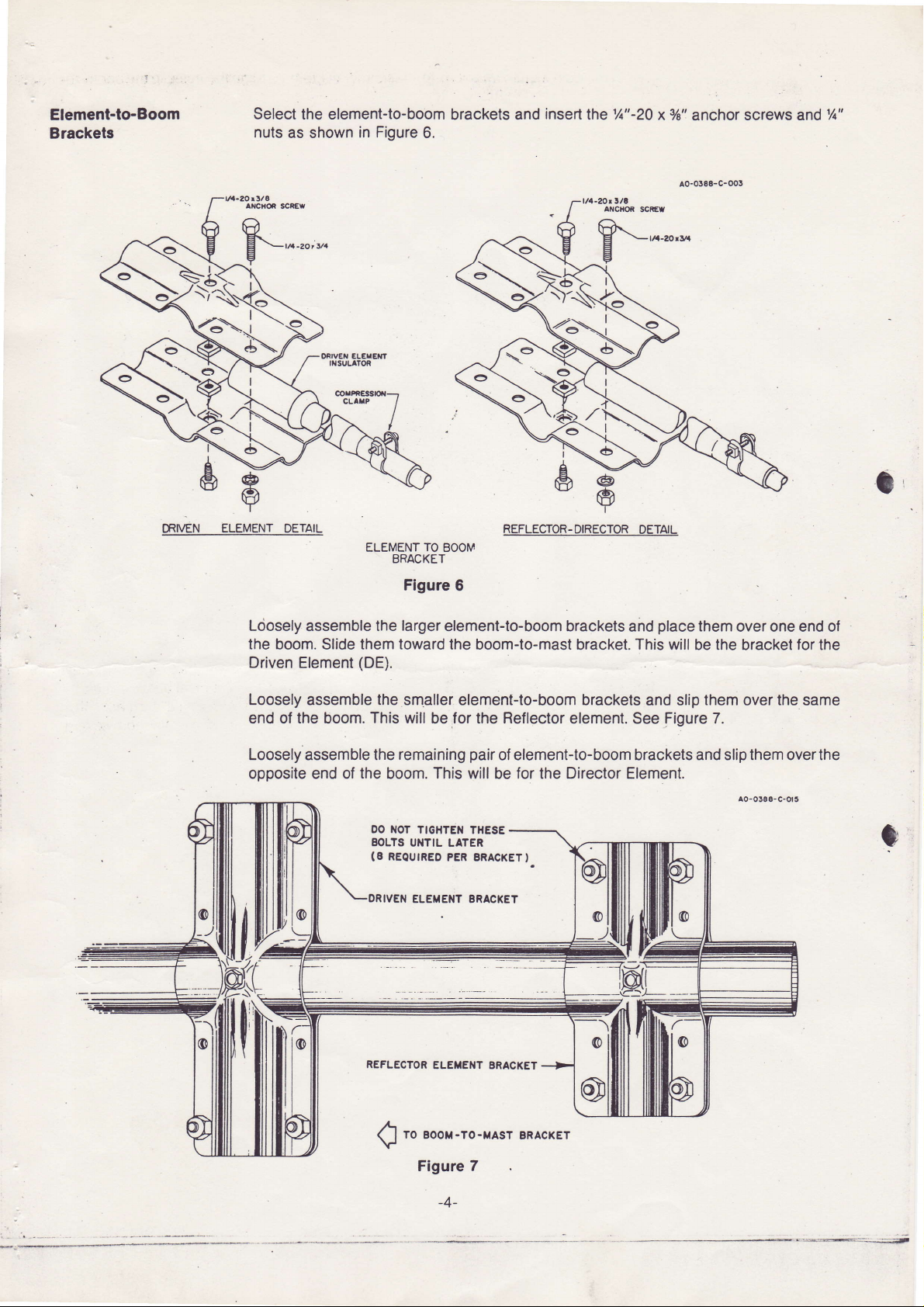
Element-to-Boom
Brackels
Select
nuts
as shown
the element-to-boom
in Figure
brackets
6.
and
insert
lhe
%"-20
xVe"
anchot screws and
1A"
MVEN
t$:
ELEMENT
ORIVET €L€IEf,'
If,SULATOR
DETAIL
ELEMENT
TO
BRACKET
Figure 6
Lciosely assemble the larger
the boom.
Driven Element
Loosely
end of
assemble
the
Loosely assemble the
opposite end of
them toward
Slide
(DE).
This will
boom.
the
the
smaller element-to-boom brackets
be
remaining
boom. This will be for the Director Element.
REFLECTOR-
EOOM
element-to-boom brackets
lhe boom-to-mast
for
Reflector
the
pair
of element-to-boom brackets and slip them overthe
DIRECTOR
and
bracket.
element.
DETAIL
place
them
over one end of
This will
and
See
be the bracket for the
slip them over the same
Figure 7.
AO-O3E8-C-0t5
e
DO
NOT TIGHTEN
EOLTS
UIITIL
(8
REOUIREO
IVEII
ELEIIENT ERACKET
REFLECTOR
to
Boot
Q
Figure 7
THESE
LATER
PER ERACKETI
ELETEI{T ERACKET
-ro-rrAsr
-4-
BRA.KET
l,:'<'
o
_l
 Loading...