

Hy-Gain TH-3JRS Instruction Manual

TH-3JRS
Tri-band HF 3 Elements Beam
300 Industrial Park Road, Starkville, MS 39759
Ph: (662) 323-8538 FAX: (662) 323-6551
Covers 10, 15 and 20 Meters
INSTRUCTION MANUAL
WARNING
The TH3JR-S is constructed of taper-swaged
aluminum tubing which offers low wind resis-
Installation of this product near power lines
is dangerous. For your safety, follow the
installation directions.
tance. It can be rotated with a heavy-duty TV
rotator. The light weight is ideal for rooftop or
lightweight tower installations. The antenna features super strength stainless steel hardware and a
General Description
The TH3JR-S antenna was designed for the Ham
boom-to-mast bracket that will fit masts up to 2
inches in diameter.
who has space limitations but still wants top performance on 10, 15 and 20 meters.
Specifications
Electrical
Forward Gain Up to 8 dBi
Front-To-Back Ratio 25 dB
VSWR at Resonance Less than 1.5:1
Nominal Impedance 50 ohms
Power Capability (Transmitter Output) 600 Watt PEP, 300 Watt AM
Lightning Protection DC ground
Mechanical
Net Weight 21 lbs. (11.7 kg)
Boom Length 12 ft. (3.65 m)
Longest Element 27’3” (8.30m)
Turning Radius 14’9” (4.49m)
Wind Survival 80 mph (128 kmph)
Accepts Mast 1 ¼” to 2” (32 mm to 51mm)
Surface Area 3.35 sq. ft. (0.32 sq. m)
Effective Moment* 310 ft. lb. (53 kg-m)
Wind Load at 80 MPH 87 lbs. (39.4 kg)
Hardware Stainless Steel (except for U-Bolts and some small parts)
Suitable Rotators Hy-Gain AR-40 or CD-45II
*Effective Moment is defined as the product of the antenna weight and turning radius.
Step-By-Step Assembl
y
NOTE: When unpacking your antenna, check
the inside of all tubing for parts (clamps, insulators, smaller tubing, etc.). To conserve
space during packing, these smaller articles ar e
put inside large pieces.
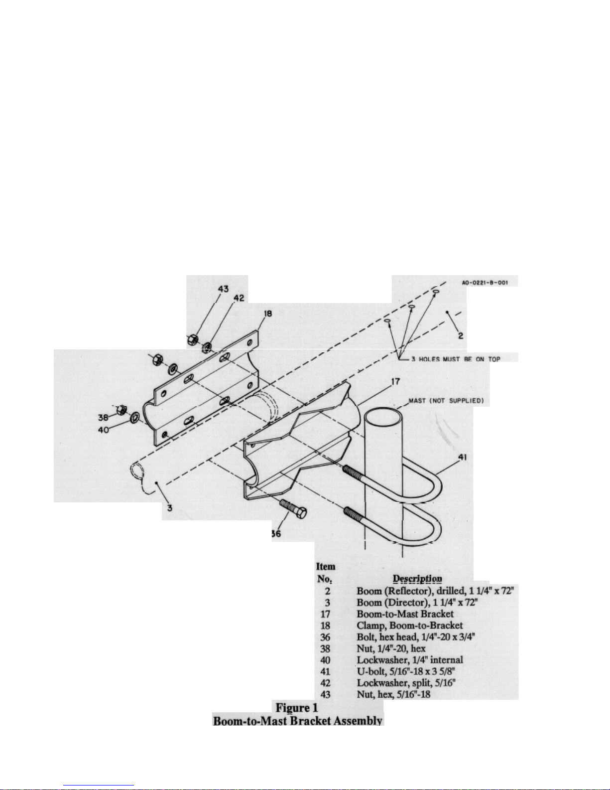
Select the two boom sections (1 1/4" x 72")
and boom-to-mast brackets.
Assemble the two halves of the boom-to-mast
bracket by placing the 1/4" x 3/4" screws in the
four outside holes as shown in Figure
1. DO
NOT tighten at this time.
Slip the boom sections into the boom-to-mast
bracket until they meet in the middle. Make
certain the drilled holes on the reflector end are
on top and close to the boom-to-mast bracket,
then tighten the bolts securely.
NOTE: The reflector portion of the boom has
holes drilled in it for the beta match. Make sure
they are on top when you tighten the boom-to-
Place a 11/4" caplug on each end of the
Insert the two U-bolts into the boom-to-mast
bracket and start the 5/16" nuts and

Figure 2
Reflector/Director Detail
Start at the reflector end (boom section that has
the hole drilled in it) and measure approximately
1" from the end of the boom and install the
elementboom bracket as shown in Figure 2. Onl y
tighten the hardware enough to keep t he bracket
in place. Final positioning of this element will
depend upon placement of the driven element and
the dimensions from Figure 4.
Select the Rl sections (7/8" x 72") of tubing and
slip one end of each in each side of the brack et
and tighten the bracket securely with the
exception of the two anchor screws.
DO NOT
tighten at this time
Measure along the boom 65 1/8" from the center
of the reflector element-to-boom bracket and install the driven element-to-boom bracket. Select
the DE sections and slip the driven element insulators onto one end of the DE1 sections (7/8" x
72").
Slip the insulated end of the DE1 section into the
driven element bracket and tighten securely. See
Figure 3 for proper installation.
DO NOT tighten
the anchor screws at this time.
Measure 74" from the center of the d riven el ement
bracket to the center of the director and install the
director element-to-boom bracket. Select and install the D1 sections (7/8" x 72") by slipping one
into each side of the bracket and tighten securel y.
DO NOT tighten the anchor screws at this time.
Now recheck the measurement and make certain
all the elements are aligned evenly.

Figure 3
Driven Element Bracket Assembly
NOTE: At this time select your mode of transmission - either Phone or Continuous Wave (CW).
Refer to the dimensions for your mode of transmission. Use the same mode for all dimensions.
Select the 10-meter reflector trap (marked REF)
and a #6 tubing clamp and slip it on the end of Rl.
Slip the longest end of the 10-meter trap into the
Rl section to the dimensions given for your mode
of transmission. Tighten the tubing clamp slightly.
See Figure 4.
Select R2 (3/4" x 10 1/2") and slip it onto the 10meter trap assembly. Slip one #6 tubing clamp on
each end of R2. Tighten slightly.
 Loading...