

Hy-Gain T-2XX Instructions
Starkville, MS 39759 US
A
TAILTWISTER
y
b
,
Ph: (662) 323-9538 FAX: (662) 323-6551
INSTRUCTION MANUAL
GENERAL DESCRIPTION
T-2X / T-2XX
TM Rotator
T-2X has 110 VAC Controller
T-2XX has 220 VAC Controller
The Tailtwister rotator consists of an extra heav
duty rotator and the control unit. The rotator is
designed to be mounted on a plate inside a tower.
A mast to support and turn large communications
beams is then attached to the top of the rotator.
However, in some instances, mast mounting is
desired. The Lower Mast Support Kit, PN
5146710, contains a lower mast support and the
necessary hardware to facilitate mounting the
Tailtwister rotator on top of a mast.
New features in the Tailtwister include an 8 pin
Cinch® connector on the rear panel of the
control, a chassis ground connection on the 120
VAC model, a high-strength drive gear, a weather
proof AMP connector at the rotor unit, and RF
eads on the potentiometer lines.
CinchTm a Division of Labinal Components & Systems
The rotator unit must be wired to the control unit
with an 8-wire cable. The control unit must be
placed inside the house or other protected location.
Included in the shipping box are:
A. Instruction Manual
B. Rotator Unit
C. Controller Unit
D. Mounting Hardware Pack
E. Connector Parts Pack
Due to the wide variety of towe rs available, each
installation will have different requirements. The
gauge of the 8-wire cable to connect the control
unit to the rotator depends upon the distance
between the rotator and control. The longer the
distance, the larger the diameter of the wire
required. Various antennas or beams require
different installation methods. (See Table 1).
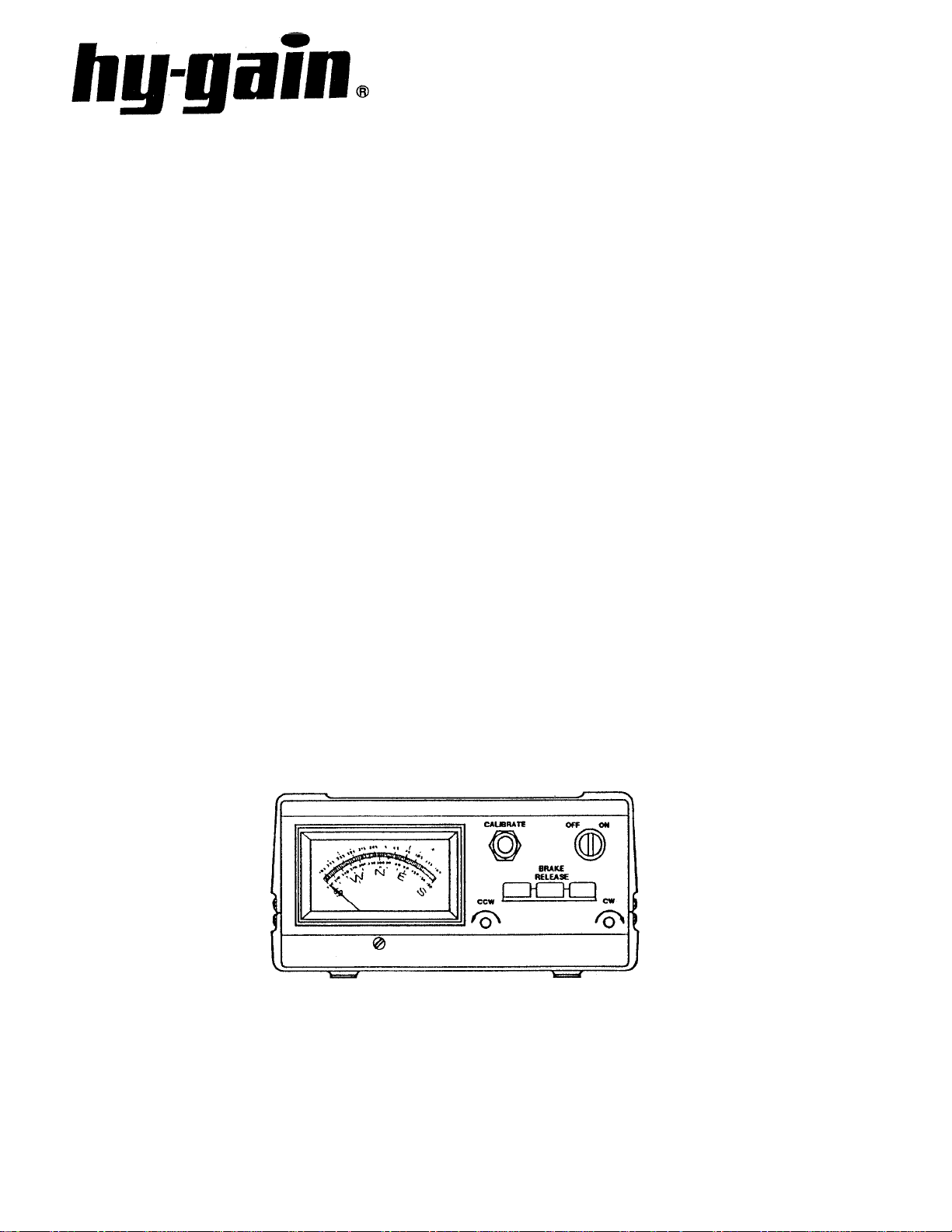
Figure 1
Control Unit - Front Panel

prop
y
,
CAUTIONS
Install
Towers, often the highest metal parts in the vicinity, require caution during
erection and placement. Extreme care must be taken during erection so that
metal towers and beams do not contact power lines even if the beams slip or
rotate
Metal towers or other position mechanisms must be placed so that if they
fracture or blow over in high winds, they cannot contact power lines, be a
hazard to individuals, or endanger property.
When not mounted within a tower with a thrust bearing, as shown in Figures 6
and 7, the rotator must be DEBATED.
erly and safel
towers fall or fracture or metal wires blow in the wind, etc.

Metal towers must be grounded properly at the tower location before the tower is
p
y
g
SSU
;
erected. This is to minimize electrical hazard and the possibility of lightning
damage. DO NOT bury bare aluminum wires or stakes in the ground. Use copper
ground stakes. The service entrance ground should be checked. The household
convenience outlet should be the 3-prong type (grounded back to the service
entrance).
• The Control Box is not weatherproof and must be located in the house, ham
shack or other protected location.
• Read this manual com
letely before proceeding.
The Tailtwister rotator has been carefully designed and manufactured to give man
years of trouble-free service when carefully and professionall y installed. It consists
of the strongest and best commercially available components.
TYPES OF INSTALLATION
There are three general types of installations (see
Figures 4, 5 and 6).
l. The recommended Installation is an "Inside"
Tower Mount with a thrust bushing or bearing
to provide support and resist high wind loads.
When the rotator is properly mounted this
way, it can be rotated to turn an antenna or
beam of 20 square feet (1.86 m2) wind surface
area. The wind loading during storms, the
rotational inertia of the beam and unbalanced
weight are more important than the dead
weight of the beam. It is important to
minimize the height of the beam above the
rotator to minimize the overturning force
induced in a high wind (see "Unbalanced
ht" and "Wind Pressure").
Wei
2. An "outside" Tower Mount (see Figure 6) is
optional. The rotator is not well protected
but the installation is simpler. With an
"Outside"Tower Mount, the rotator must be
derated to 10 square feet (.93 m2).
UNBALANCED WEIGHT AND WIND
PRE
RE
Unbalanced Weight: Weight should be as
closely balanced as possible. Unbalanced
weight creates a bending moment of force
which is concentrated on the mast at the point
where it is clamped to the rotator. This
moment tends to strain the mast at that point
and also to bind the ball bearings by creating
excessive downward pressure on one side and
upward pressure on the other. Such unbalance
places additional stress on the motor gear
train. Unbalanced weight becomes critical as
the distance from the antenna boom to the
clamping point at the rotator is increased.
Wind Pressure: Wind pressure against the
boom and elements produces a bending force
on the mast which can cause the same stresses
as unbalanced weight. To strengthen the
installation to withstand unbalanced weight
and wind pressure the top mast should be as
short and as strong as possible. In multiple
arrays the antenna with the most wind area
should be closest to the rotator.
,
3. A telescoping or other type mast (see Figure
7) can also be used. This installation is
similar to Number 2 above and requires the
optional Heavy Duty Lower Mast Support
Kit and must be derated to 10 square feet
In order to distribute the bending stress and
prevent fracture of the mast, the T2X rotator
includes a specially designed steel clampin g plate
to clamp the mast to the rotator
After procuring the type of tower or other
positioning mechanism of the owner's choice, the
next step is to wire the rotator to the control box
and check out its operation prior to installation.
WIRING AND CHECK-OUT
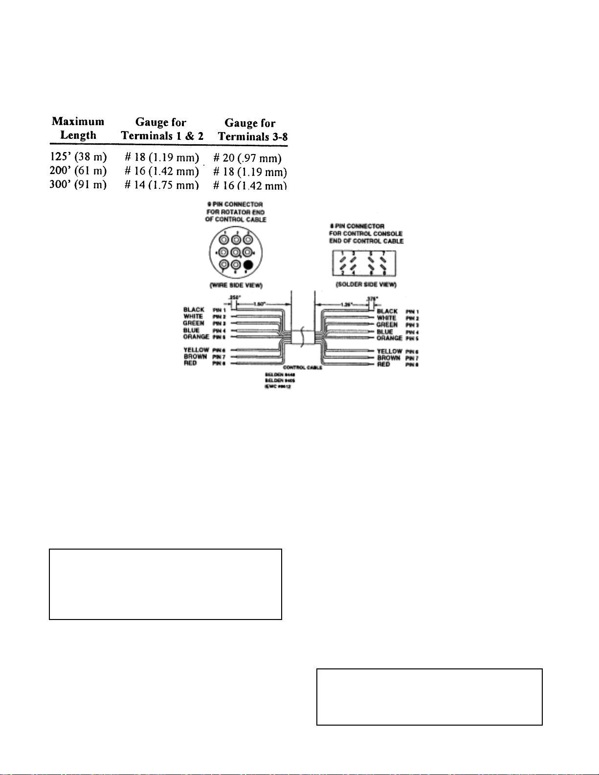
A. Decide the wire gauge (size) required and
procure the number of feet of the proper
cable (see Table 1).
Table 1
E. Turn the power switch on. The meter should
be illuminated.
F. Depress the "Brake Release" (center) lever,
then release it. An audible click should be
heard in the rotator. This is the solenoid
operating the brake wedge.
NOTE: The specifications call for heavier
gauge wire in two locations. Leads #1 and #2
must be heavier gauge and less total lead
B. Assemble the rotor cable as shown in Figure
1.
CAUTION
Shorts between terminals or grounded leads may
damage the rotator. Pay strict attention to the pin
numbers on the connectors!
C. Temporarily attach the 6 5/16"-18 x 1 5/8"
screws (Item 140) to the bottom of the rotor
unit.
D. With the rotator sitting in the upright position
and connected to the control unit by the 8wire cable, plug the control unit power cord
into a receptacle.
Figure 2
Depress the "Brake Release" (center) lever,
hold it, and simultaneously depress the CCW
direction switch (left). The rotator should
turn CCW (looking from the top). This is SE-N-WS. Release the CCW direction switch;
the rotator wil lcoast down and stop. Now
release the brake switch. The rotator is now
locked into position.
Repeat the previous step for CW direction
by depressing the brake switch first, then the
CW direction switch (right). The red lamps
I. Return the rotator to full CW position.
CAUTION
It is best to release the direction switch just prior to
the end of rotation (extreme CW or CCW position) in
order not to cause undue stress on the stop arm
and/or the gears.

ATTACHING CONTACTS TO WIRES AND
CONNECTOR
Since these contacts will be inserted into
connector blocks, their tabs mustbe carefully
rounded. Unless you have a crimpinmg tool for
installing connectors, use the following
procedure.
Repeat for each contact. Pa y close attention to the
numbered holes in the connector! Pull back
lightly on each conductor to be sure each contact
is locked in each cavit y. Once locked in place, the
contacts may only be safely removed with an
extraction tool. (Extraction tool not included).
This tool consists of a tube with an O.D. of 0.129
and an I.D. of 0.115. When inserted over the
contact from the front side, this tool compresses
the locking tabs, permitting easy removal.
MOUTING INSIDE TOWER
y
r
p
p
w
ed.
The rotator is mounted inside a tower (see Figure
4) to the flat tower plate by means of six (6) bolts
furnished in the hardware kit. Use the following
procedure:
1. Locate the rotator in the tower directl
the bushing. Note that the tower plate must be
cut out to allow the connecting 8-wire cable to
ass through the plate.
Use the tem
2. Plug the cables together and secure the cable
to the tower in such a manner that the cable
ill not be strain
3. The rotator is attached to the tower plate by
means of six (6) bolts and lockwashers (see
Figure 4). The flat tower plate must be drilled
in six (6) places using the template provided
with this manual unless the tower plate is already properly drilled.
late in the back of the manual.
unde
4
Tighten the six (6) bolts, but not to final tightness. Observe how the rotator turns. It must
rotate in such a manner as to turn the mast
concentrically in the thrust bearing.
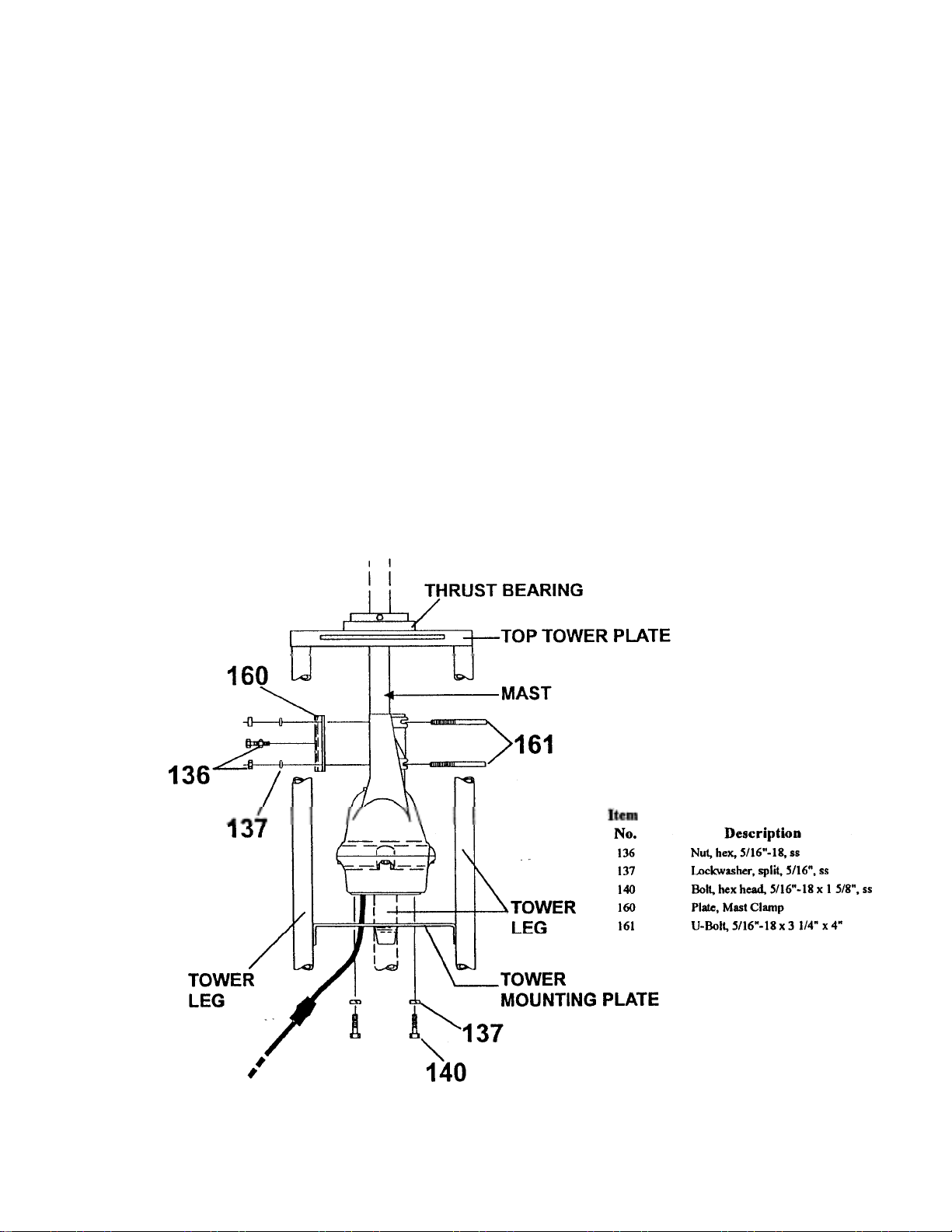
Trial assemble the mast to the top of the rotator
5
using the U-bolts nuts and lockwashers
through the rotator and clamp plate as shown
in Figure 4. The maximum mast diameter that
may be used is 2 1/16" O.D. We recommend
1 1/2" nominal steel pipe with 1.9" O.D. in
standard wall thickness of .145". For stacked
arrays or very large beams, we recommend
extra heavy-duty wall thickness of .200".
Both steel pipes can be purchased to
specification ASTM120.
NOTE: Apply a coating of heavy-duty motor oil
or grease to the threads of the st ainless steel bolts
and U-bolts to prevent seizing.
Figure 4
Rotator Mounting in a Tower

On any inside tower installation, care must be
exercised to get the antenna mast shimmed to the
exact rotational center of the rotator. The
geometry is such that a mast of 2.062" (2 1/16"
[52 mm]) O.D. pipe will be exactly centered. If
the O.D. of your mast is less than this, you should
shim out to these dimensions.
9. Return the rotator to the full CW "S"
position. Mount the beam on the mast
pointing South. The coaxial cable should be
looped in such a manner that it will not foul
or tangle when the beam turns around in a
circle to the full 360° counterclockwise
position.
OUTSIDE TOWER
6. If the rotator, top bushing and mast are
properly aligned, there should be unrestricted
rotation through 360°. If not, the rotator may
have to be moved slightly on the flat plate. If
a high quality bearing is used in the top of
the tower (recommended), the shimming
procedure must be done more carefully as
closer tolerances.are required. It is important
that the rotator does not try to turn the mast
eccentrically with the top bushing or bearing.
7. Tighten the mounting bolts carefully - to approximately 175 inch-pounds of torque.
8. Drill through the antenna mast and rotator
casting, using a 5/16" drill. Locate the hole in
the clamp plate that is furnished. Insert the
bolt through the clamp plate, mast, and
rotator and tighten all bolts to 150 inchpounds. Refer to Figure 4.
Referring to Figures 5, 6, and 7, an outside tower
or pole mount is made in the same manner except
that the rotator is fastened by four (4) bolts only
(not six) to the Lower Mast Support, PN 51467
10. Since the eccentricity of the rotator turning in
reference to the tower is no longer important, the
shimming procedure is not necessary. The four (4)
screws must be torqued to the same specification
and the 8-wire cable securel y fastened. The lower
mast should be pinned with the 5/26"-18 x 4" bolt
as shown in Figure 6.
CAUTION
The rotator is designed for vertical operation with
the bell shaped housing in the up position. Water
and other contamination will get into the motor
unit if it's mounted horizontally or upside down.
Figure 5
Rotator Mounted On Tower Top Plate
 Loading...