

Hy-Gain QK-710 Instructions

MODEL QK-710
"QUAD-BAND KIT"
FOR THE
EXPLORER 14
NOTICE
All rights in this publication are reserved. No part of the publication may be reproduced in any manner whatsoever
without the expressed written permission of Hy-Gain.

TABLE OF CONTENTS
y
p
p
p
j
p
pp
CHAPTER 1
CHAPTER 2
Preparation for Assembly
................................................................................................................... 2-1 Assembl
CHAPTER 3
Installation.......................................................................................................................................
...... 3-1 Attachment of Driven Element Support
Ropes.............................................................................. 3-1 VSWR Curves for 30 and 40
CHAPTER 4
CHAPTER 5
of the
Pag
e
CHAPTER 6
Service Information
............................................................................................................................. 6-1 Parts
LIST OF ILLUSTRATIONS
Figure
1Ca
2 Antenna Dimensions for O
3 40 Meter Ad
4 Antenna Dimensions for O
5 10 MHz Beta Match Extension 2-5
6Driven Element Su
7VSWR Charts 3-2
Attachment
acity-Hat Clam
erations of the Explorer 14 at 7 MHz 2-2
ustment Chart ............................................................ 2-3
eration of the Explorer 14 at 10.1 MHz 2-4
ort Ropes 3-1
Pag
2-1
CHAPTER 1
Genera
escriptio
l D
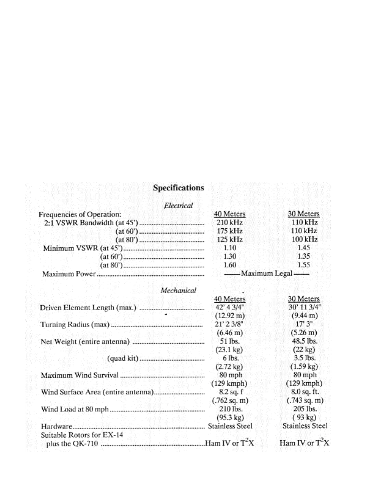
The Hy-Gain QK-710 will allow the
conversion of the Explorer 14 antenna to
cover either the 30, 20, 15 and 10 meter bands
or the 40, 20, 15 , and 10 meter bands. This kit
will allow the driven element of this beam to
resonate on either 30 or 40 meters with
VSWR less than 1.6:1 at resonance. The 2:1
VSWR bandwidth is typically 100 kHz on 30
meters and 175 kHz on 40 meters.
n
Stainless steel hardware and clamps are supplied for-all electrical and most mechanical
connections. A driv en element supp ort rope is
supplied to help support the additi onal weight
of the driven element with either 30 meters or
40 meters added. The Ham IV or T
Rotators are recommended to be used with the
modified Explorer 1 4 anten na.
NOTE: Throughout this manual references
will be made to refer to your Explorer 14
manual. Have your Explorer 14 manual ha ndy
during the entire installation.
2
X
CHAPTER 4
y
p
p
Preparation for Assembl
Choose a large cl ear area to wo rk on your Explorer 14 antenna. The area must be at least
14' x 31' (4.27 m x 9.45 m) for the 30 meter
modification or 14' x 43' (4.27 m x 13.11 m)
for the 40 meter modification. You may wish
to drive a 5 foot (1.53 m) length of mast
material into th e ground to attach the an tenna
to while working on it.
Check all parts against the Parts List to make
sure no parts are missing.
All tubing supplied with the QK-710
telescopes together. Make all measurements
to the given dimensions, plus or minus, no
more than 1/8 inch! Double and Triple
checkALL dimensions after assembly.
Assembly of th e QK-71 0 fo r 7 MH z
eration
O
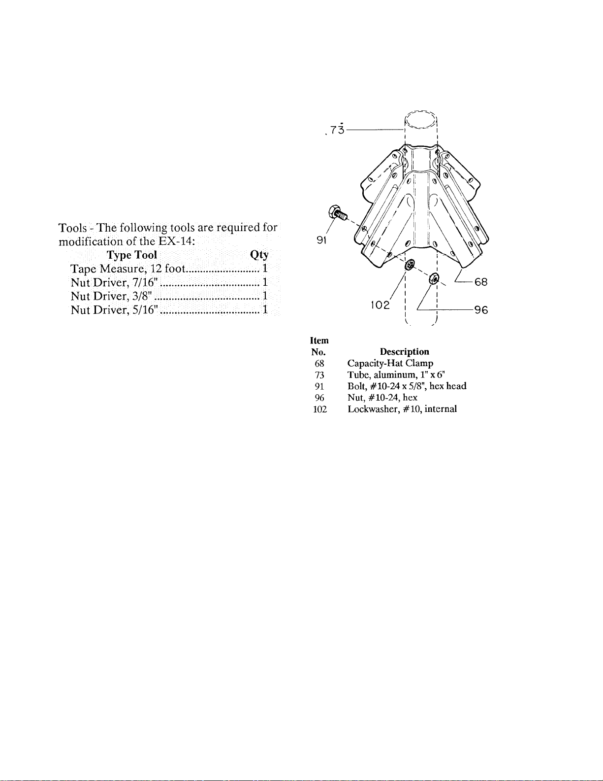
Select the capacity-hat clamps (Item 68) and
loosely assembl e a set of four (4) clamps onto
each of the 1" x 6" tubes as shown in Figure
1. Center these clamps on the tubes, before
tightening.
Install a #10 tubing clamp at each end of the
1" x 6" tube and insert the 7/16" x 15" tubes
into the capacity-hat clamps. At this time
tighten all bolts used on the capacity-hat
clamp. Place 7/16" endcaps on the en ds of the
15" tubes.
Figure 1 Capacit y-
Hat Clam
Remove the DE-3 (7/16" x 37") and the 1/2"
compression clamps (older system) or the #6
tubing clamp (new syste m) from the Explorer
14 driven element. Adjust the DE-2 to 37 1/2"
and slide the 15 meter trap all the way into the
DE-2. Reti ghten these tw o clamps s ecurely on
both sides of the antenna. Loosen the sleevespacer insulators and the sleeve boom-toelement brackets and adjust the spacing of t he
sleeves to 7 inches.
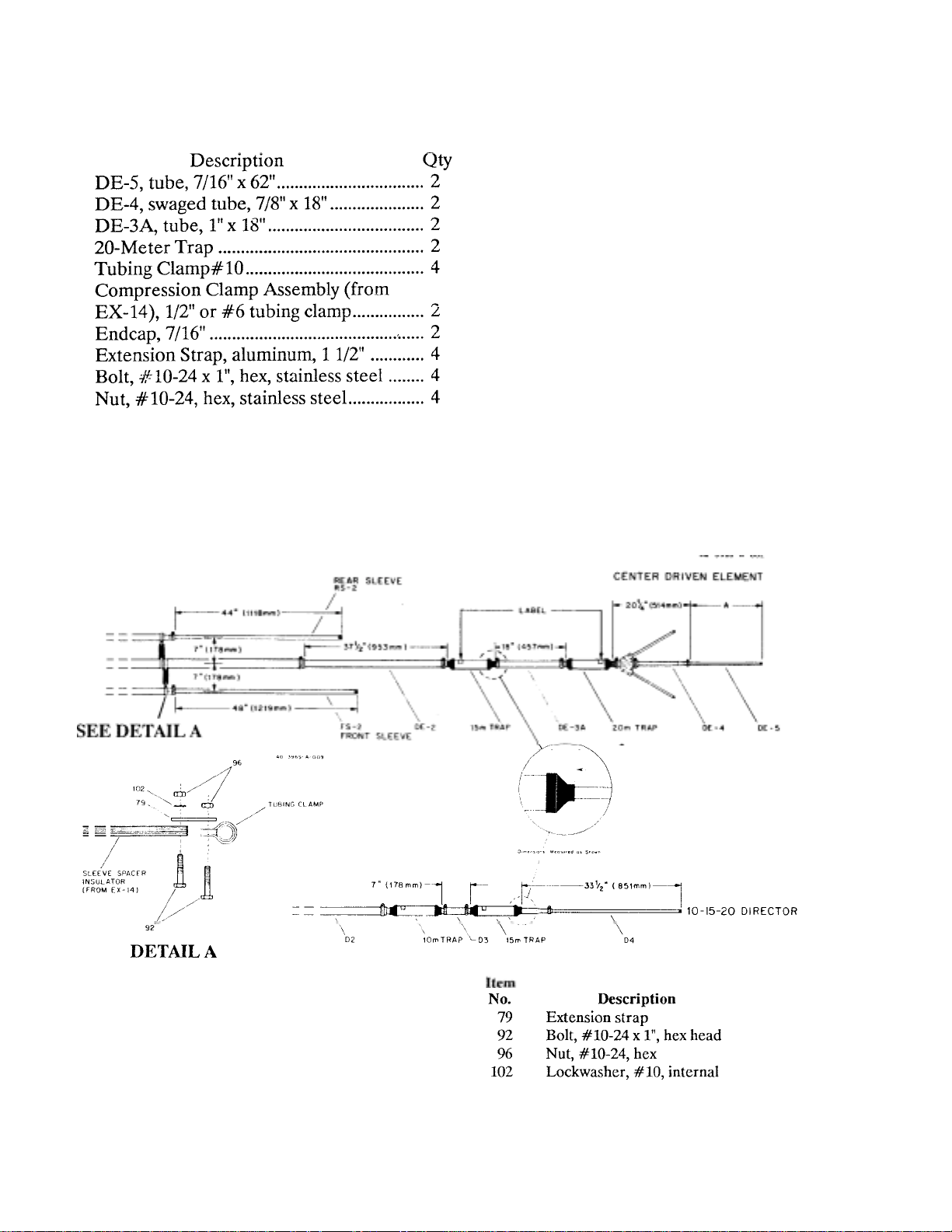
In addition to the capacity-hat assemblies,
select the following parts:
Assemble these parts as shown in Figure 2.
Determine Dimensions "A" from Figure
Use the 11/2" aluminum extension straps,
#1024 x 1" bolts and #10-24 hex nuts to
extend the sleeve spacer insulators to 7
inches.
Assemble the element with the dr ain holes of
the 20 meter tr ap facing toward the gro und.
Also, adjust sections D-3 and D-4 to the
dimensions shown in Figure 2.
The beta match will not be used in this configuration, so the beta match assembly from
the Explorer 14 may be completely removed.
This includes Items 21 and 37 (two), beta
shorting clamp assembly, b eta support clamp,
and insulator assembly and all other hardware
used to connect these assemblies together.
See Figure 8, of the Explore r 14 manual.
Tighten all clamps and brackets that were previously loosened.
Figure 2 Antenna Dimen sions for Oper ation of the Expl orer 14
at 7 MHz
 Loading...